

Page 1
Operating Guide
Actuator t ype
AM E 655 -1
AME 658 SD-1
AME 658 SU-1
AM E 68 5-1
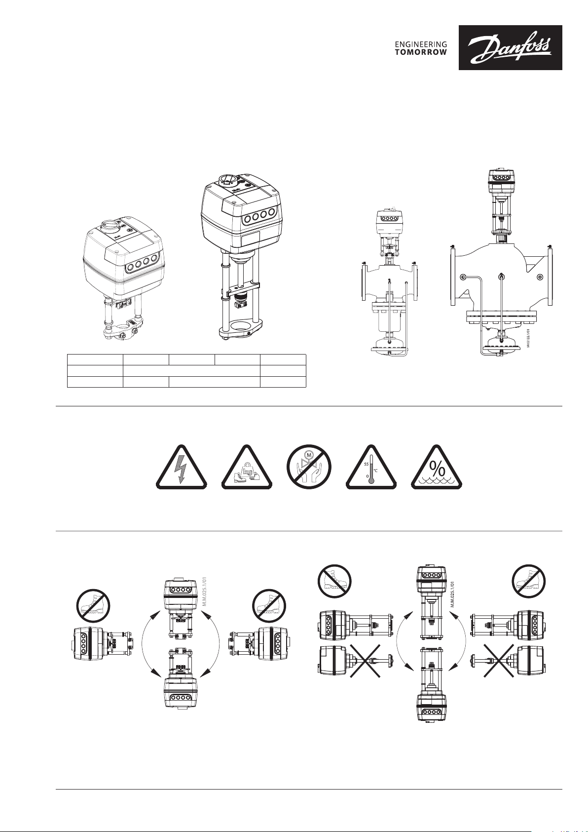
AME 655-1/658 SD-1/658 SU-1 & AME 685-1
Ste m Trav el 32 mm 32 mm
Travel Speed 2 or 6 s/mm 4 or 6 s/mm 3 or 6 s/mm
MAINTENANCE
FREE
AME 655-1/658 SD-1/658 SU-1
(AB-Q M 5” & 6” / 5” & 6” HF)
5-95 % RH
no condensing
AME 685-1
(AB -Q M 8”-10 ”)
AME 685-1AME 655-1/658 SD-1/658 SU-1
AQ323736153498en-000103 | 1© Danfoss | 2021.03
Page 2
AME 655-1/658 SD-1/658 SU-1 & AME 685-1
3-5 Nm
2×
AM E 655-1/658 S D-1/6 58 SU-1
❶
=
=
AUTO
13 mm 4 mm
①
③
④
2×
②
2×
2×
12-15 Nm
2×
①
③
2×
④
12-15 Nm
2×
②
❷
AM E 655-1
①
②
③
=
=
AUTO
3,5 - 4,5 mm
× 0,7mm
4 mm T 10
AQ323736153498en-000103 2 | © Danfoss | 2021.03
Page 3
AME 655-1/658 SD-1/658 SU-1 & AME 685-1
3-5 Nm
2×
3-5 Nm
2×
AME 658 SD-1
1×
AME 658 SU-1
①
②
③
④
⑦
⑤
⑨
⑥
⑥
1×
③
①
④
②
⑧
⑤
⑦
© Danfoss | 2021.03 | 3AQ323736153498en-000103
Page 4
AME 655-1/658 SD-1/658 SU-1 & AME 685-1
3-5 Nm
2×
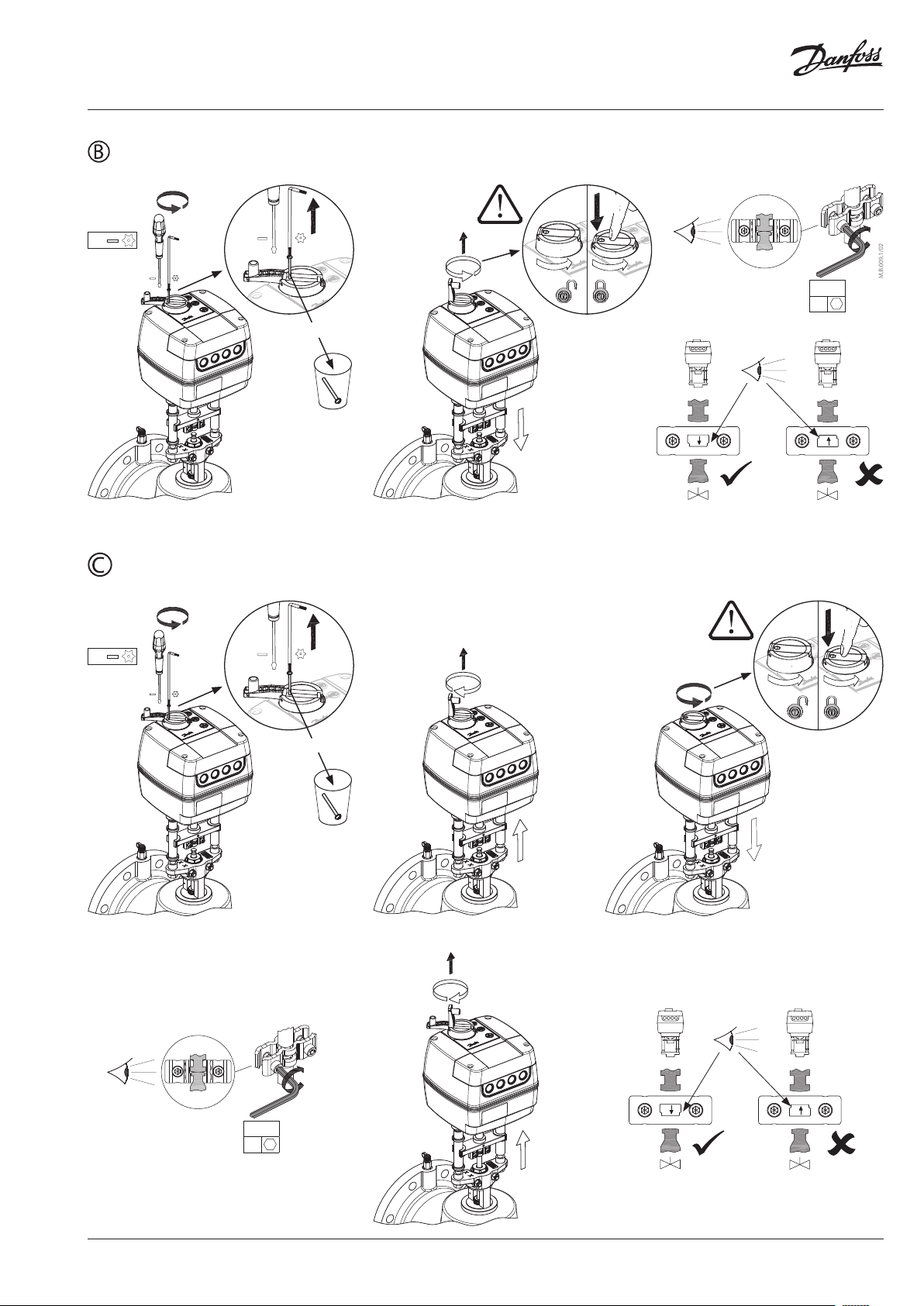
AM E 68 5-1
❸
⑥
=
=
AUTO
HN 10 5 mm
⑨
⑩
②
⑬
⑪
①
③
⑤
⑫
⑭
40 Nm
1×
⑦
⑧
④
HH10
⑮
❹
AM E 68 5-1
AQ323736153498en-000103 4 | © Danfoss | 2021.03
Page 5

AME 655-1/658 SD-1/658 SU-1 & AME 685-1
❺
=
AUTO
①
②
2×
③
④
⑥
AME 655-1/658 SD-1/658 SU-1 & AME 685-1 operating as modulating version
⑤
M16, M20 / MP16 1/2’’
=
3,5– 4,5 mm ×
0,7 mm
M16
M20
M16
1/2’’
⑦
SN 0 V Neutral
SP 24 V AC/DC
4
4, 5 SP (AC)
SP
5
Power
supply
SP output
-max 4 A
-min 3 W
T 10
AME 658 SD/SU-1
AME 655/685-1:
DIP 6 OFF (1a, 1b)
DIP 6 ON (2a, 2b)
⑧
AME 655/685-1 operating
as 3-point version
CONTROLLER
1
SP
3
GND 0 V Neutral
0(2 )-10 V
Y
0(4) -20 mA
0(2 )-10 V
X
0(4) -20 mA
Input
Input
Output
⑦
SN 0 V Neutral
1,3 24 V AC/DC
Y1
4, 5 SP(AC)
1
SP
3
K2
K4
Y2
Power
supply
24~ output
-max 4 A
-min 3 W
Input
AME655/685-1
© Danfoss | 2021.03 | 5AQ323736153498en-000103
Page 6

AME 655-1/658 SD-1/658 SU-1 & AME 685-1
❻
①
Actuator type AME 655-1 AME 658 SD-1 AME 658 SU-1 AME 685-1
Travel speed 2 or 6 s/m 4 or 6 s/m 3 or 6 s/m
T [sec] Travel speed × H
②
H
③
④
AQ323736153498en-000103 6 | © Danfoss | 2021.03
Page 7

AME 655-1/658 SD-1/658 SU-1 & AME 685-1
❻ ⑤
>5s = RESET
Max. retracted
Max. extended
=
=
AUTO
max. retracted
Set new retract
Set new extended
max. extended
>5s = RESET
Kv
>5s = RESET
Kv
© Danfoss | 2021.03 | 7AQ323736153498en-000103
Page 8

AME 655-1/658 SD-1/658 SU-1 & AME 685-1
S4
❻ ⑥
⑦
input
1 3
output
45
output
45
S5
V
❼
⑧
⑨
②
③
0,7 -1,1 Nm
2×
=
=
AUTO
3,5– 4,5 mm ×
0,7 mm
T 10
①
AQ323736153498en-000103 8 | © Danfoss | 2021.03
Page 9

AME 655-1/658 SD-1/658 SU-1 & AME 685-1
❽
LED Indication type Operating mode
Green LED:
Constantly lit Positioni ng mode - Actuator i s retracting th e stem
Constantly lit Positioni ng mode - Actuator i s extending the s tem
F lashing (1 s cycle) Self stro king mode - Actu ator is retracti ng the stem
F lashing (1 s cycle) Self stro king mode - Actu ator is extendin g the stem
Yellow LED:
Constantly lit Stationar y mode - Actuato r has reached upp er end position (ret racted stem)
Constantly lit Stationar y mode - Actuato r has reached bot tom end position (e xtended stem)
Red LED:
Red/ Yellow LE D
Dark
❾
F lashing
Constantly lit Stand-By mode
F lashing Error Mode
F lashing (1 s cycle)
F lashing (1 s cycle)
No indication No power sup ply
Stationar y mode - Single bl ink when Y signal is pr esents and doub le blinks when Y
signal is no t connected)
Set up stro ke limitation (ret racted stem)
Set up stro ke limitation (ex tended stem)
①
>5s = RESET
F lashing
(1 s cycle)
AUTO
=
=
②
F lashing
(1 s cycle)
LED : Green
F lashing
LED : Yellow
© Danfoss | 2021.03 | 9AQ323736153498en-000103
Page 10

AME 655-1/658 SD-1/658 SU-1 & AME 685-1
❿
AM E 68 5-1AM E 655-1/658 S D-1/6 58 SU-1
②
①
(1)
1s = STAND BY−ON
STAND BY−O FF
Constantly lit
LED : Red
AM E 68 5-1AM E 655-1/658 S D-1/6 58 SU-1
AQ323736153498en-000103 10 | © Danfoss | 2021.03
Page 11
AME 655-1/658 SD-1/658 SU-1 & AME 685-1
operation
operation
AM E 655-1
AME 658 SD/SU-1
AM E 685 -1
ENGLISH
Safety Notes
To avoid personal injury and damage
to devices, it is absolutely essential for
be read carefully and reviewed prior to
assembly and use.
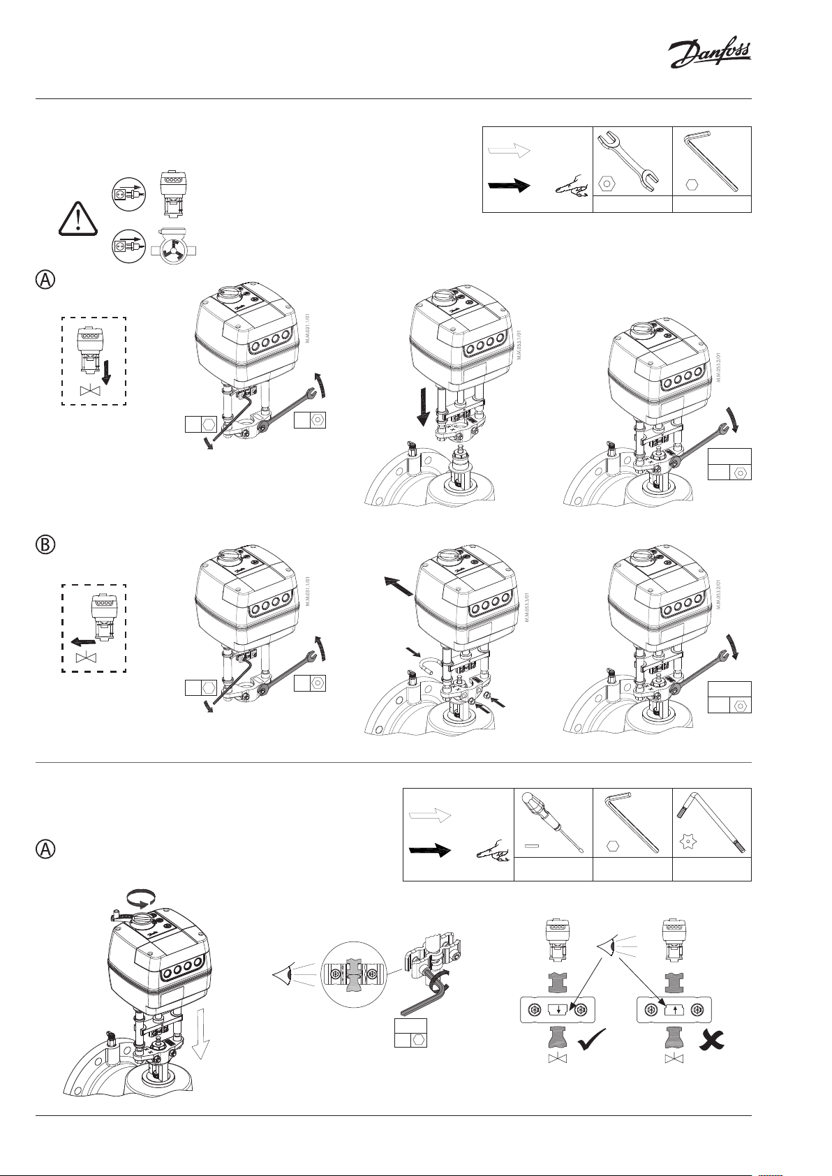
Do not dismantle actuator with the safety spring
function! There is risk of injury and death in the
event of improper handling!
Switch off the pump and power line before
mounting and wiring the actuator.
The actuator is heavy. Handle with care to avoid
injury or product damage.
Wiring
and SW2 (INV/DIR) are active when is no power
supply on terminal SP and AME actuator operated
as AM V.
Actuator mounting to valve AME 655-1/
658 SD-1/ 658 SU-1 ❶
Stem connections AME 658 SD-1/ AME
658 SU-1 ❷
Actuator mounting to valve AME 685-1 ❸
Stem connections
Electrical connection ❺
DIP switch setting ❻
SW1: FAST/SLOW – Speed selection ①
- FA S T;
- SLOW;
SW2: DIR/INV – Direct or inverse acting
- DIR; the actuator is directly reacting to input
- INV; the actuator is inversely reacting to
SW3: 2-10V/0-10V – Input/output ③
- 2-10V; the input signal ranges from 2-10 V
- 0-10V; the input signal ranges from 0-10 V
Signal range selector sets Y & X signals.
SW4: LIN/MDF – Characteristic modification
- LIN; linear correlation between Y signal and
- MDF (Modified); enables modified
The function enables to change MCV (Motorised
Control Valve) characteristic (for example
linear to logarithmic and logarithmic to linear)
and works with all combinations of DIP switch
settings.
these instructions and safety notes to
Do not touch anythin g on the PCB! Do
not remove the servi ce cover before
the power supply is fu lly switched off.
termina ls 4 and 5 is 4 A. M in. power is 3W.
Max. al lowed curre nt output on
NOTE: Only basic function as SW1 (Fast/Slow)
AM E 685 -1
selector ②
signal
input signal
(voltage input) or 4-20 mA (current input)
(voltage input) or 0 -20 mA (current input)
function ④
stem position
correlation between Y signal and stem
position. Degree of modification depends on
setting of potentiometer CM.
❹
SW5: 100 %/95 % – Stroke limitation ⑤
Adjustable stroke limitation of retracted or
extended actuator stem position.
DIP 5 needs to be reset prior to procedure (5.2)
to 100 % (5.1) and set to 95 % (5.3) until the
self-stroking procedure has concluded (5.4).
Retracted icon (5.5) on actuator will blink redyellow when actuator stops at max. retracted
stem position (5.5) and will blink as long as it
is not set to a new retracted position (5.6) by
pressing buttons to set the required
position (observe flow on flow meter). Press and
hold reset button for 5 seconds (5.7) and then
set new extended stem position by pressing
buttons .
Extended icon (5.8) will blink red-yellow as long
as it is not set to new extended position by
pressing and holding reset button for 5 seconds.
SW6: C/P – Output signal mode selector ⑥
① An output signal is present on terminal 4
when the position of the actuator is equal
to or lower than the S4 set point. An output
signal is present on terminal 5 when the
position of the actuator is equal to or higher
than the S5 set point.
SW6: C; provides a constant output signal on
terminals 4&5, regardless of the input signal.
SW6: P; provides a pulse signal through parallel
or cascade electrical wiring input 1 & 3
dependents from the controller to output
terminals 4&5.
SW7: Smart function selector: ⑦
- OFF; the actuator does not try to detect
oscillations in the system
- ON; the actuator enables special antioscillation algorithm – In case control signal
Y on certain point oscillates looking from
time perspective, algorithm starts to lower
the amplification of the output to the valve.
Instead of having static characteristics
actuator changes to dynamic characteristics.
After the control signal does not oscillate
anymore, output to the valve slowly returns
back to static characteristics.
SW8: Uy/Iy – Input signal type selector: ⑧
- Uy; input signal Y is set to voltage (V)
- Iy; input signal Y is set to current (mA)
SW9: Ux/Ix – Output signal type selector: ⑨
- Ux; output signal X is set to voltage (V)
- Ix; output signal X is set to current (mA)
NOTE: Y detection is disabled if SW8 is set to
ON position and SW3 is set to OFF position.
Functions accessible from cover
RESET button
The actuators has an external RESET button,
which is located on the top cover of the actuator
next to the LED indicators. With this button
you can enable or disable standby mode (press
once) or self-stroking mode (press and hold for 5
seconds). See next paragraph for more details.
Final step of electrical connection ❼
LED signalisation ❽
Calibration mode ❾
Calibration mode begins automatically the first
time the actuator is powered on. To start the
self-stroking procedure, press and hold the
RESET button for 5 seconds ① until the green
light starts flashing. End positions of the valve
are automatically set and the actuator goes into
stationary mode ② and starts responding to the
control signal.
Manual Operation ❿
Mechanical and electrical operation
must not be used at the same tim e!
AME 655-1/658 SD-1/658 SU-1 and AME 685-1
actuators can be manually positioned when in
standby mode or when there is no power supply
(mechanically).
Actuator type
Stand-By mode
Press the RESET button ① to enter standby
mode. The actuator stops in the current position
and stops responding to any control signal. A
red light remains constantly lit. You can now
manually operate the actuator ②.
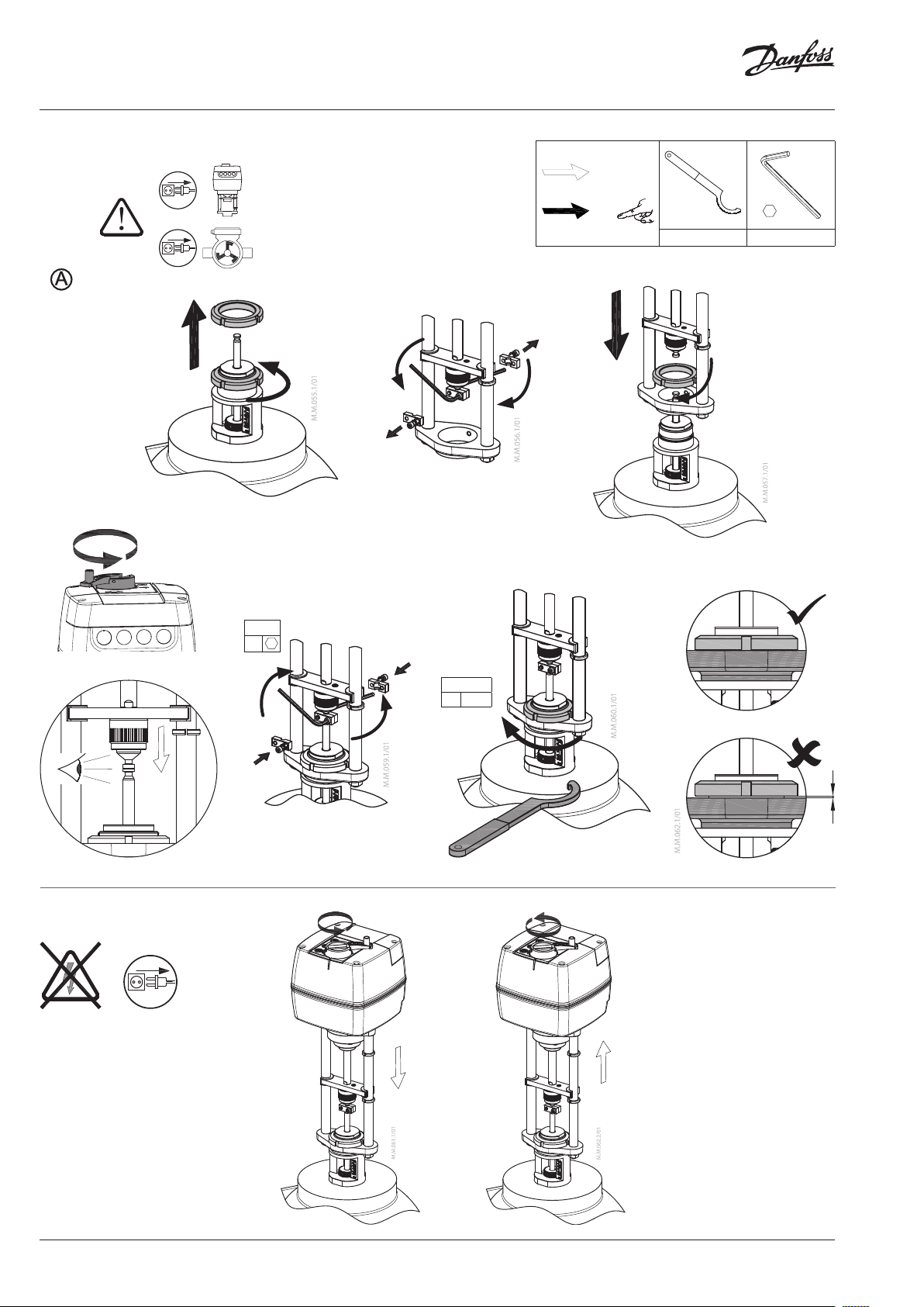
Mechanical manual operation
AME 655-1/658 SD-1/658 SU-1 and AME 685-1
actuators have a knob & crank on the top of the
housing which enables manual positioning of
the actuator.
same time!
Electrical manual operation
AME 655-1/658 SD-1/658 SU-1 and AME 685-1
actuators have two buttons on the top of the
housing that are used for electrical manual
positioning (up or down) if the actuator is
in standby mode. First, press and hold the
RESET button ① until the actuator goes to
standby mode (red LED is lit). By pressing the
button, the stem will be extended and
by pressing the button, the stem will be
retracted.
Mechanical
Use Mechanical manual operation
only when the power is d isconnected.
Mechanical and electrical operation
are not allowed to be used at the
Electrical
© Danfoss | 2021.03 | 11AQ323736153498en-000103
Page 12

AME 655-1/658 SD-1/658 SU-1 & AME 685-1
Part Nam e / 部件名称
Motor / 电机 X O O O O O
Beari ng cover / 轴承盖
Nut inse rt / 插入螺母
O: Indica tes that this hazar dous substance con tained in all of the h omogeneous ma terial for this par t is below the limi t requirement in GB /T 26572;
O: 表示该 有害物质在该部件所有均质材 料中的含量均在GB/ T 26572规定 的限量要求以下。
X: Indica tes that this hazar dous substance co ntained in at least o ne of the homogen eous material fo r this part is above th e limit requirem entw in GB/T 26572;
X: 表示该有害物质至少在该部件的某一均质材料中的含量超出GB /T 26572规定的限量 要求。
PB / 铅 Hg / 汞 Cd / 镉 Cr( VI) / 六价铬 PBB / 多溴联苯 PBDE / 多溴二 苯醚
X O O O O O
X O O O O O
Hazardous Substances Table / 有害物质表
73694850 / AQ323736153498en-00010312 | © Danfoss | DHS-SDBT/SI | 2021.03
 Loading...