

Page 1
Data sheet
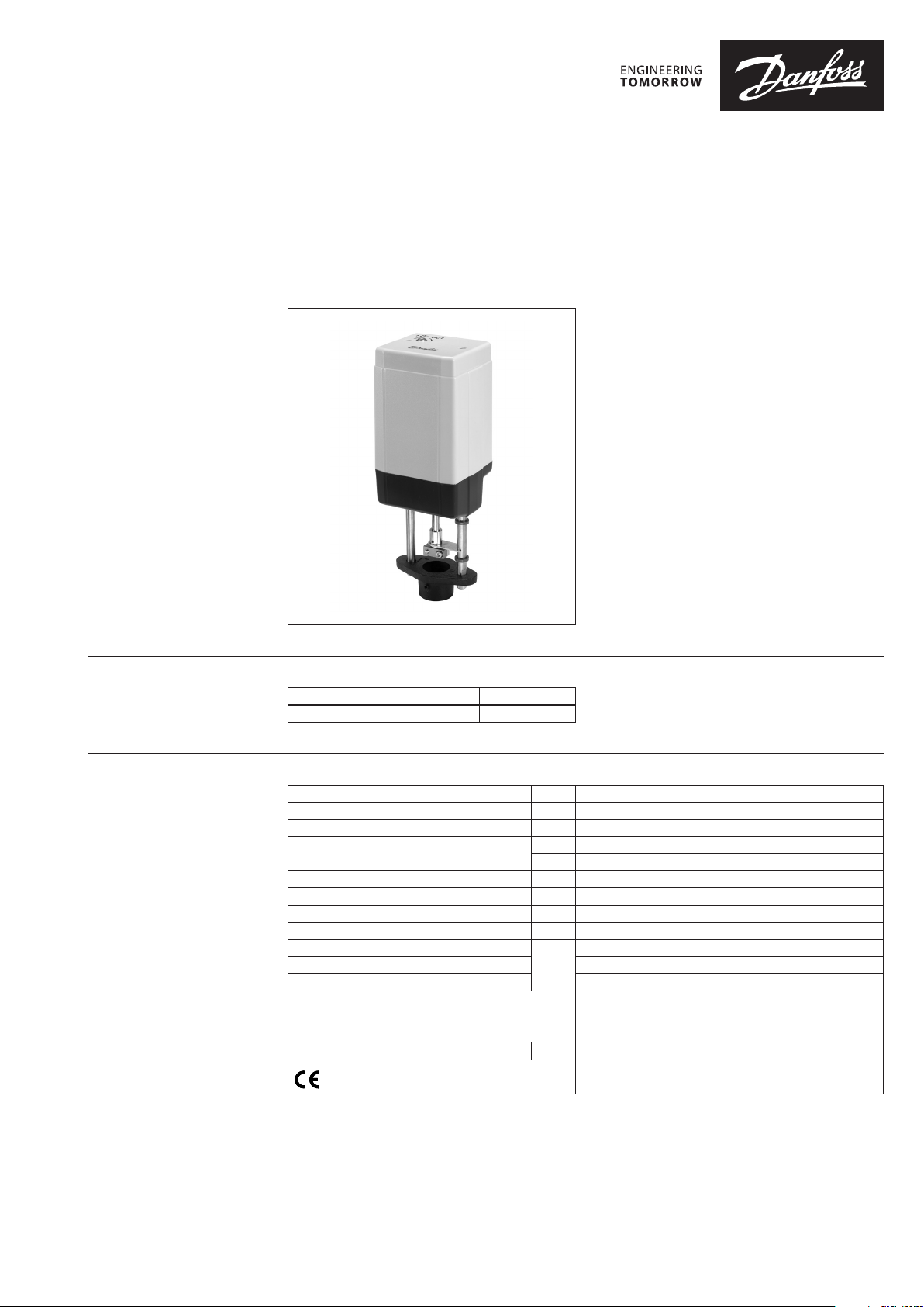
Actuator for modulating control
AME 55 QM
Description
Ordering
Actuator is used with pressure independent
balancing and control large valve type AB-QM
DN 125 and DN 150.
Features:
• “Self stroking” function
• Load related “Switch off“ function that
prevents overloading
• Diagnostic LED
Main data:
• Nominal voltage: 24 VAC, 50 Hz/60 Hz
• Control input signal:
- 0(4)-20 mA
- 0(2)-10 V
• Force: 2000 N
• Stroke: 40 mm
• Speed: 8 s/mm
• Max. medium temperature: 200 °C
• Manual operation
Typ e Supply voltage Code No.
AME 55 QM 24 V~ 082H3078
Technical data
Power supply V 24~; +10 to – 15%
Power consumption VA 9
Frequency Hz 50 / 60
Control input Y
Output signal X V 0 – 10 (2 – 10)
Close of force N 2000
Max. stroke mm 40
Speed s/mm 8
Max. medium temperature
Ambient temperature 0 – 55
Storage and transpor t temp. –40 to +70
Ambient humidity 95% r.h., non-condensing
Protection class III safet y extra-low voltage
Degree of protection IP 54
Weight kg 3.8
- marking in accordance with standards
V 0 – 10 (2 – 10) Ri = 24 kΩ
mA 0 – 20 (4 – 20) Ri = 500 Ω
200
°C
Low Voltage Directive 73/23/EEC
EMC-Directive 2006/95/EEC,
EN 60730-1, EN 60730-2-14
© Danfoss | 2021.09 AI000086478777en-010202 | 1
Page 2
Data sheet AME 55 QM
Installation
Wiring
24 Vac only.
Wiring length
0-50 m 0.75 mm
> 50 m 1.5 mm
Recommended
square of the wiring
2
2
Automatic self stroking feature
When power is first applied, the actuator will
automatically adjust to the length of the valve
stroke. Subsequently, the self stroking feature
can be re-initialised by changing position of SW9.
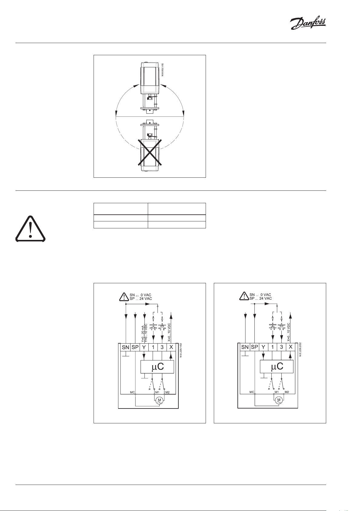
Mechanical
The actuator should be mounted with the valve
stem in either horizontal position or pointing
upwards. Use a 4 mm Allen key (not supplied) to
fit the actuator to the valve body.
Allow for necessary clearance for maintenance
purposes.
The valve has position indication rings
which should be pushed together before
commissioning; after stroking they indicate the
ends of the stroke.
Electrical
Electrical connections can be accessed by
removing the cover. Two M16 × 1.5 cable entries
are provided. Both entries are provided with a
rubber grommet for use with flexible cable. Note
that in order to maintain the enclosure IP rating,
appropriate cable glands must be used.
Diagnostic LED
The red diagnostic LED is located on the pcb
under the cover. It provides indication of three
operational states:
• Actuator Healthy (Permanently ON),
• Self Stroking (Flashes once per second),
• Error (Flashes 3 times per second - seek
technical assistance).
Wiring for modulating control Wiring for 3-point control
Note:
If switch SW6 is set t o ON than use this wiring.
2 | AI000086478777en-010202 © Danfoss | 2021.09
Page 3
Data sheet AME 55 QM
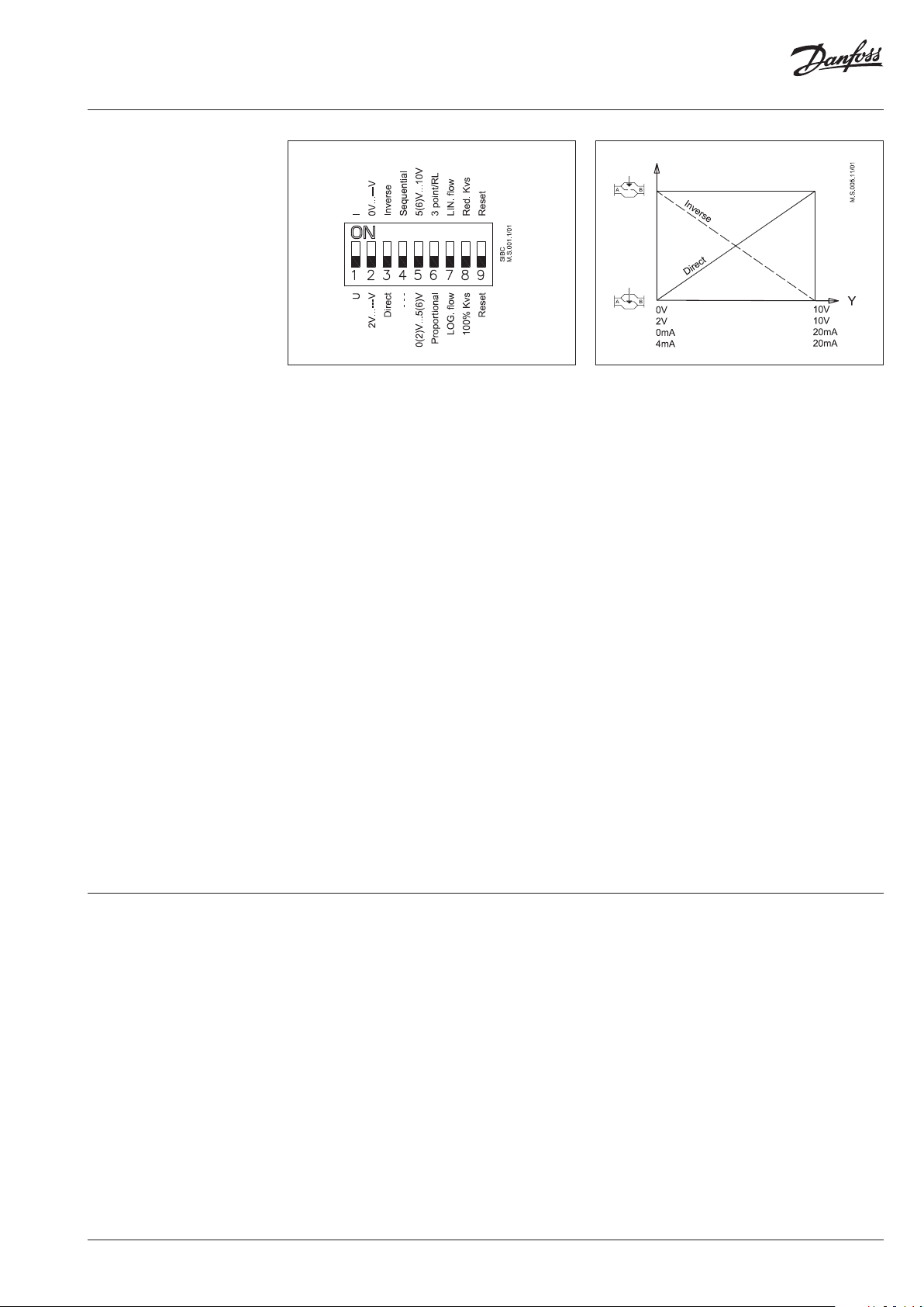
DIP switch setting
The actuator has a function selection DIP switch
under the removable cover. In particular, if SW6
is set to ON, the actuator will perform as 3-point
actuator.
The switch provides the following functions:
•
SW1: U/I - Input signal type selector:
If set to OFF position, voltage input is selected. If
set to ON position, current input is selected.
•
SW2: 0/2 - Input signal range selector:
If set to OFF position, the input signal is in the
range from 2 V to 10 V (voltage input)
or from 4 mA to 20 mA (current input). If set to
ON position, the input signal is in the range from
0 V to 10 V (voltage input) or from 0 mA to 20 mA
(current input).
•
SW3: D/I - Direct or inverse acting selector:
If set to OFF position, the actuator is direct acting
(stem contracts as voltage increases). If actuator
is set to ON position the actuator is inverse
acting (stem extracts as voltage increases).
•
SW4: —/Seq - Normal or sequential mode
selector:
If set to OFF position, the actuator is working
in range 0(2)..10V or 0(4)..20mA. If set to ON
position, the actuator is working in sequential
range; 0(2)..5 (6)V or (0(4)..10 (12)mA) or (5(6)..10V)
or (10(12)..20mA).
•
SW5: 0..5V/5...10V - Input signal range in
sequential mode:
If set to OFF position, the actuator is working in
sequential range 0(2)..5 (6)V or 0(4)..10 (12)mA.
If set to ON position, the actuator is working in
sequential range; 5(6)..10V or 10(12)..20mA.
•
SW6: Prop./3-pnt - Modulating or 3-point mode
selector:
If set to OFF position, the actuator is working
normally according to control signal. If set to
ON position, the actuator is working as 3-point
actuator.
For this operation please refer to page 2
(wiring 3-point control).
When DIP switch SW6 is set to ON than all
functions from other DIP switch become inactive.
•
SW7: LOG/LIN - Equal percentage or linear flow
through valve selector:
If set to OFF position, the flow through valve
is equal percentage. If set to ON position, the
flow through valve is linear according to control
signal.
•
SW8: 100% KVS/Reduced KVS:
To be set to OFF position (no sense in combination
with AB-QM).
•
SW9: Reset:
Changing this switch position will cause the
actuator to go through a self stroking cycle.
Commissioning
Complete the mechanical and electrical
installation and perform the necessary checks
and tests:
• Isolate control medium. (e.g. self stroking
in a steam application without suitable
mechanical isolation could cause a hazard).
• Apply the power. Note that the actuator will
now perform the self stroking function.
• Apply the appropriate control signal and
check the valve stem direction is correct for
the application.
• Ensure that the actuator drives the valve over
its full stroke, by applying the appropriate
control signal. This action will set the valve
stroke length.
The unit is now fully commissioned.
Commissioning / testing feature
The actuator can be driven to the fully open or
closed positions (depending on valve type) by
connecting SN to terminals 1 or 3.
AI000086478777en-010202 | 3© Danfoss | 2021.09
Page 4
Data sheet AME 55 QM
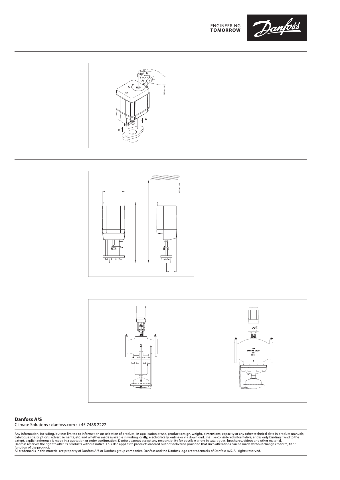
Manual override
Dimensions
The manual override is applied by rotating the
4 mm Allen key (not supplied) to the required
position. Observe the direction of the rotation
symbol.
• Disconnect power supply
• Adjust valve position using an Allen key
• Set valve to closed position
• Restore power supply
If manual override has been used then X and Y
signal are not correct until the actuator reaches
its end position. If this is not accepted reset the
actuator, or apply accessory active return signal
kit.
120
min 478
328
Actuator - valve
combinations
55
AME 55 QM + AB-QM DN 125 AME 55 QM + AB-QM DN 150
© Danfoss | DCS-S/SI | 2021.094 | AI000086478777en-010202
 Loading...