

Daikin RZQ71KAVLT, RZQ71KBV1, RZQ71KBV4A, RQ71KBV4A Service Manual
REMOVAL
PROCEDURE
Si281314E
SERVICE MANUAL
3 HP Class
Outdoor Unit
Inverter
Pair Type

Service Manual
Removal Procedure
Outdoor Unit
Applicable Models
zHeat Pump
RZQ71KAVLT

Si281314E
Table of Contents
1. Procedure to Remove Outside Panels and Related Parts ......................2
2. Procedure to Remove Propeller Fan and Fan Motor ..............................3
3. Procedure to Remove Switch Box ..........................................................4
4. Procedure to Remove PCB Assy (1).......................................................5
5. Procedure to Remove Assy (2)...............................................................6
6. Procedure to Remove Assy (3)...............................................................7
7. Procedure to Remove Low Pressure Thermistor,
Electronic Expansion Valve, and Others.................................................8
8. Procedure to Remove Thermistor...........................................................9
9. Procedure to Remove Four Way Valve.................................................10
10.Procedure to Remove Compressor.......................................................11
Removal Procedure 1

Procedure to Remove Outside Panels and Related Parts Si281314E
1. Procedure to Remove Outside Panels and Related Parts
Procedure Warning Be sure to wait for 10 minutes or more after turning off all power
supplies before disassembling work.
Step
1
Remove the front panel
2 (the front panel of the
side panel), after
removing the 1 screw
and pushing the front
panel downward.
2
Remove the top panel,
after removing the 8
screws.
3
Remove the front panel
1, after removing the 7
screws.
Procedure Points
Top panel
Hooks
Suction grille
4
Remove the right side
panel, after removing
the 5 screws.
5
Remove the front panel
of the piping cover,
after removing the 1
screw.
6
Remove the side panel
of the piping cover,
after removing the 4
screws.
7
Hold the lower part (2
positions) and pull
frontward. Remove
from the top hooks
using a flathead
screwdriver etc. and
then pull downward the
whole suction grille to
remove it.
Front panel 1
Front panel 2
Side panel of
piping cover
Front panel of
piping cover
Right
panel
2 Removal Procedure
Si281314E Procedure to Remove Propeller Fan and Fan Motor
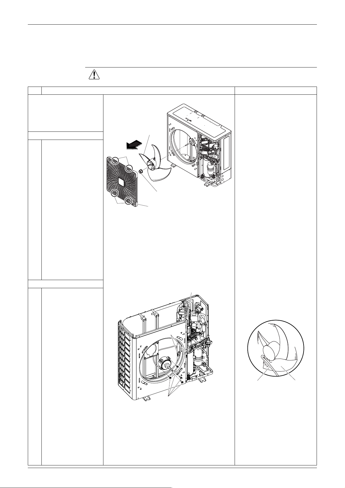
2. Procedure to Remove Propeller Fan and Fan Motor
Procedure Warning Be sure to wait for 10 minutes or more after turning off all power
supplies before disassembling work.
Step
Remove the front panel 2,
following the procedure
indicated at "Removal of
Outside Panels and
Related Parts".
1. Remove the propeller fan
1
Remove the 4 screws
that fix the discharge
grille. Remove from 4
hooks at upper and
lower side and then
remove the discharge
grille.
Procedure Points
Propeller fan
Hooks
Fan setting nut
2
Remove the fan setting
nut that fixes the
propeller fan.
3
∗ Remove the top
panel, following the
procedure indicated
at "Removal of
Outside Panels and
Related Parts".
2. Remove the fan motor
1
Remove the connector
for the fan motor from
the printed wiring board
(PWB). (Refer to ∗1)
2
Remove the 3 clamps
which fix the lead wire.
(3 hooks of partition
plate)
3
Remove the 3 screws
of the front panel and
then pull lead wire
frontward.
Hooks
Discharge grille
Connector for fan motor (X106A)
Clamp
In case of removing the
connector, do not pull the
lead wire. Hold the
connector part and press the
hook.
Lead wire Propeller fan
Precaution for the motor
4
Pull out the fan motor,
after removing the 4
fixing bolts.
4 bolts
installation:
Be sure to fix the lead wire of
the motor. Otherwise the
lead wire might be entangled
with the motor and causes
failure.
Removal Procedure 3
 Loading...