

Page 1
OPERATION MANUAL
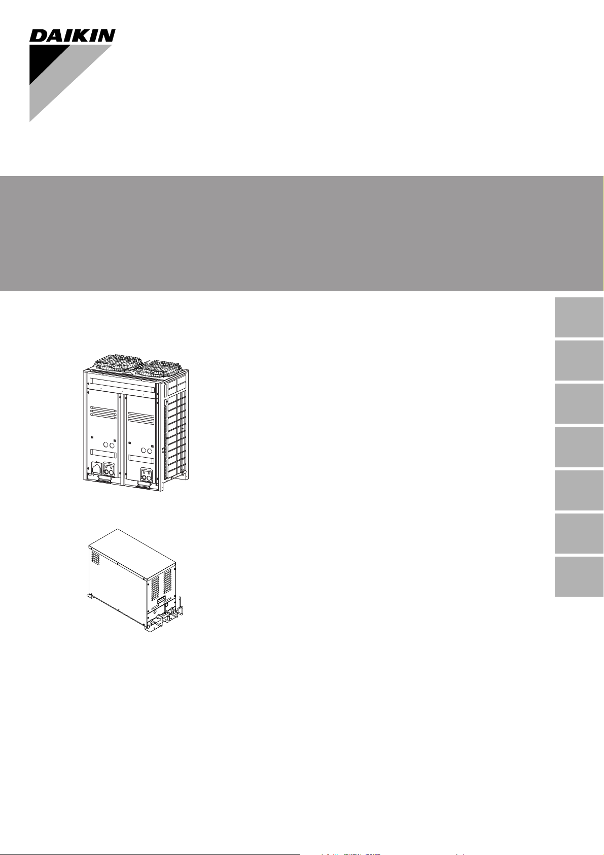
CONVENI-PACK
Outdoor Unit
(LRYEQ16AY1(E))
Operation manual
CONVENI-PACK
Betriebsanweisung
CONVENI-PACK
Manuel d’utilisation
CONVENI-PACK
Manual de operación
CONVENI-PACK
Manuale d’uso
CONVENI-PACK
Gebruiksaanwijzing
CONVENI-PACK
Manual de funcionamento
CONVENI-PACK
English
Deutsch
Français
Español
Italiano
Nederlands
Portugues
Booster Unit
(LCBKQ3AV1(E))
Page 2

Thank you for purchasing this Daikin CONVENI-PACK. Carefully read this operation
manual before using the CONVENI-PACK.
It will tell you how to use the unit properly
and help you if any trouble occurs. After
reading the manual, keep it in your custody
for future reference. If the user changes,
be sure to hand over the operation manual
to the next user. After receiving the warranty card from the dealer, store it in a safe
place.
Wir danken Ihnen dafür, dass Sie sich für
dieses Daikin-Kondensatorgerät
entschieden haben. Lesen Sie diese Bedienungsanleitung sorgfältig durch, bevor
Sie das Kondensatorgerät in Betrieb nehmen. Sie erfahren hier, wie die Einheit korrekt genutzt wird, und es ist lhnen bei
Störungen behilflich. Lesen Sie das Handbuch sorgfältig und bewahren Sie es für
den späteren Gebrauch sorgfältig auf.
Wenn Sie das Gerät einem neuen
Benutzer übergeben, händigen Sie ihm
auch unbedingt die Bedienungsanleitung
aus. Bewahren Sie die Garantiekarte, die
Sie von Ihrem Händler erhalten haben,
ebenfalls an einem sicheren Ort auf.
Nous vous remercions d’avoir acheté cette
unité de condensation Daikin. Avant d’utiliser l’unité de condensation, veuillez lire
attentivement ce manuel d’utilisation. Il
vous enseignera à utiliser correctement
l’unité et vous aidera en cas de panne.
Après lecture du manuel, veuillez le conserver à des fins de consultation
ultérieure. Si l’utilisateur change, veillez à
confier ce manuel d’utilisation à l’utilisateur
suivant. Après réception de la carte de
garantie transmise par le revendeur, conservez-la dans un endroit sûr.
Gracias por adquirir haber adquirido esta
unidad de condensación Daikin. Lea
cuidadosamente este manual de operación antes de usar la unidad de condensación. El manual explica cómo usar la
unidad correctamente, proporcionándole
información de y lo ayuda en caso de que
surjan problemas. Una vez leído el manual, consérvelo en lugar seguro para futuras referencias.
Si el usuario cambia, En caso de cambio
de ususario, asegúrese de entregar el
manual de operación al próximo éste
último. usuario. Cuando reciba la tarjeta de
garantía del distribuidor, guárdela en un
lugar seguro.
Vi ringraziamo per aver acquistato questa
unità condensante Daikin. Leggere attentamente il presente manuale d’uso prima
di utilizzare l’unità condensante. Contiene
le istruzioni per usare correttamente l’unità
e per rimediare ad eventuali problemi di
funzionamento. Dopo aver letto il manuale,
conservatelo per il futuro. Se il prodotto
dovesse essere usato da un altro utente,
assicurarsi di consegnare il manuale d’uso
al nuovo utente. Dopo aver ricevuto la
scheda di garanzia dal vostro rivenditore,
conservatela in un luogo sicuro.
Hartelijk dank voor de aanschaf van deze
Daikin condensatie-unit. Lees deze
gebruiksaanwijzing aandachtig door voordat u de condensatie-unit gebruikt. In de
gebruiksaanwijzing kunt u lezen hoe u het
apparaat op de juiste manier gebruikt en
wat u kunt doen bij storingen. Nadat u de
handleiding heeft gelezen, dient u deze te
bewaren om hem in toekomst te kunnen
raadplegen. Als het apparaat overgedragen wordt aan een nieuwe gebruiker,
dient u ook de gebruiksaanwijzing mee te
geven. Berg de garantiekaart op een
veilige plek op, zodra u deze van de dealer
heeft ontvangen.
Obrigado por escolher esta unidade de
condensação Daikin. Leia este manual de
operação antes de utilizar a unidade de
condensação. Nele obterá O manual
contém informações sobre o modo de utilizar correctamente o aparelho e ajuda na
eventualidade de ocorrência de problemas. Após ler a leitura do manual, guardeo para futura referência. Se houver
mudança de usuário, não esqueça de
entregar-lhe o manual de operaçãoEm
caso de mudança do utilizador, garanta
que o manual de operação é entregue ao
novo utilizador.
Após receber o cartão de garantia do revendedor, guarde-o em num lugar seguro.
Page 3
LRYEQ16AY1(E)
LCBKQ3AV1(E)
CONVENI-PACK
Operation manual
CONTENTS
1. SAFETY PRECAUTIONS ...............................1
2. NAME OF PART.............................................. 4
3. WHAT TO DO BEFORE OPERATION ............ 4
4. REMOTE CONTROLLER AND COOL/HEAT
SELECTOR: NAME AND FUNCTION OF
EACH SWITCH AND DISPLAY....................... 5
5. OPERATION PROCEDURE ........................... 6
6. OPTIMUM OPERATION ................................. 9
7. CARE AND CLEANING METHOD................ 10
8. TROUBLESHOOTING .................................. 10
9. INSPECTION ................................................ 12
10. PRODUCT MODELS AND
MAIN SPECIFICATIONS............................... 13
11. AFTER-SALE SERVICE AND
WARRANTY.................................................. 14
Important information regarding the refrigerant
used
This product contains fluorinated greenhouse gases
covered by the Kyoto Protocol.
Refrigerant type R410A
(1)
GWP
(1)
GWP = global warming potential
value
1975
∗ Values are indicated in F-gas regulations (EC)
No.842/2006, Annex I, Parts 1 and 2.
Periodical inspections for refrigerant leaks may be
required depending on European or local legislation.
Please contact your local dealer for more information.
1. SAFETY PRECAUTIONS
To gain full advantage of the CONVENI-PACK’s
functions and to avoid malfunction due to mishandling, we recommend that you read this instruction
manual carefully before use.
This CONVENI-PACK is classified under “appliances not accessible to the general public”.
• The precautions described herein are classi-
fied as WARNING and CAUTION. They both
contain important information regarding
safety. Be sure to observe all precautions
without fail.
WAR NING ....... Failure to follow these instruc-
tions properly may result in personal injury or loss of life.
CAUTION ........ Failure to observe these
instructions properly may result
in property damage or personal
injury, which may be serious
depending on the circumstances.
• After reading, keep this manual in a conve-
nient place so that you can refer to it whenever
necessary. If the equipment is transferred to a
new user, be sure also to hand over the manual.
WARNING
Be aware that prolonged, direct exposure to
cool or warm air from the air conditioner, or
to air that is too cool or too warm can be
harmful to your physical condition and
health.
When the CONVENI-PACK is malfunctioning
(giving off a burning odour, etc.) turn off
power to the unit and contact your local
dealer.
Continued operation under such circumstances
may result in a failure, electric shocks or fire hazards.
Consult your local dealer about installation
work.
Doing the work yourself may result in water leakage, electric shocks or fire hazards.
Consult your local dealer regarding modification, repair and maintenance of the CONVENI-PACK.
Improper workmanship may result in water leakage, electric shocks or fire hazards.
Do not place objects, including rods, your fingers, etc., in the air inlet or outlet.
Injury may result due to contact with the CONVENI-PACK’s high-speed fan blades.
Never touch the air outlet or the horizontal
blades while the swing flap is in operation.
Fingers may become caught or the unit may break
down.
Beware of fire in case of refrigerant leakage.
If the CONVENI-PACK is not operating correctly
(i.e. the interior temperature of the CONVENIPACK does not drop efficiently), refrigerant leakage could be the cause.
Consult your dealer for assistance.
The refrigerant within the CONVENI-PACK is
safe and normally does not leak.
However, in the event of a leakage, contact with
a naked burner, heater or cooker may result in
generation of noxious gas.
English 1
Page 4
Do not longer use the CONVENI-PACK until a
qualified service person confirms that the leakage has been repaired.
Consult your local dealer regarding what to
do in case of refrigerant leakage.
When the CONVENI-PACK is to be installed in a
small room, it is necessary to take proper measures so that the amount of any leaked refrigerant does not exceed the concentration limit in the
event of a leakage. Otherwise, this may lead to
an accident due to oxygen depletion.
Contact professional personnel about
attachment of accessories and be sure to
use only accessories specified by the manufacturer.
If a defect results from your own workmanship, it
may result in water leaks, electric shock or fire.
Consult your local dealer regarding relocation and reinstallation of the CONVENIPACK.
Improper installation work may result in leakage,
electric shocks or fire hazards.
Do not replace fuses.
Do not use improper fuses, copper or other wires
as a substitute, as this may result in electric
shock, fire, injury or damage to the unit.
Be sure to earth the unit.
Do not earth the unit to a utility pipe, lightning
conductor or telephone earth lead. Imperfect
earthing may result in electric shocks or fire.
A high surge current from lightning or other
sources may cause damage to the CONVENIPAC K.
Be sure to install an earth leakage breaker.
Failure to install an earth leakage breaker may
result in electric shocks or fire.
Consult the dealer if the CONVENI-PACK submerges owing to a natural disaster, such as a
flood or typhoon.
Do not operate the CONVENI-PACK in that
case, or otherwise a malfunction, electric shock,
or fire may result.
Do not start or stop operating the CONVENIPACK with the power supply breaker turned ON
or OFF.
Otherwise, fire or water leakage may result. Furthermore, because power failure compensation
is set, the fan will rotate abruptly, which may
result in injury.
Do not use the product in the atmosphere contaminated with oil vapor, such as cooking oil or
machine oil vapor.
Oil vapor may cause crack damage, electric
shocks, or fire.
Do not use the product in places with excessive oily smoke, such as cooking rooms, or in
places with flammable gas, corrosive gas, or
metal dust.
Using the product in such places may cause fire
or product failures.
Do not use flammable materials (e.g., hairspray
or insecticide) near the product.
Do not clean the product with organic solvents such as paint thinner.
The use of organic solvents may cause crack
damage to the product, electric shocks, or fire.
Do not keep in the unit anything volatile or
flammable.
Doing so may result in explosion or fire.
Be sure to use a dedicated power supply for
the CONVENI-PACK.
The use of any other power supply may cause
heat generation, fire, or product failures.
CAUTION
Do not use the CONVENI-PACK for purposes
other than those for which it is intended.
Do not use the CONVENI-PACK for cooling precision instruments, works of art as this may
adversely affect the performance, quality and/or
longevity of the object concerned.
Do not use the unit for water cooling use.
Freezing may result.
Do not remove the unit’s fan guard.
The guard protects against the unit’s high speed
fan, which may cause injury.
Do not place objects that are susceptible to
moisture directly beneath the indoor or outdoor units.
Under certain conditions, condensation on the
main unit or refrigerant pipes, air filter dirt or drain
blockage may cause dripping, resulting in fouling
or failure of the object concerned.
To avoid oxygen depletion, ensure that the
room is adequately ventilated if equipment
such as a burner is used together with the
CONVENI-PACK.
After prolonged use, check the unit stand
and its mounts for damage.
If left in a damaged condition, the unit may fall and
cause injury.
Do not place flammable sprays or operate
spray containers near the unit as this may
result in fire.
Be sure to stop the operation of the unit and
turn off the power circuit breaker at the time
of cleaning, maintenance and inspection.
Otherwise, electric shock or injury may result.
Turn off the power supply if the unit is not
used for a long time.
Otherwise, dust gathered may result in heat generation or ignition.
To avoid electric shocks, do not operate with
wet hands.
Do not place appliances that produce naked
flames in places exposed to the air flow from
the unit as this may impair combustion of the
burner.
2 English
Page 5

Do not place heaters directly below the unit,
as resulting heat can cause deformation.
Do not allow a child to mount on the outdoor
unit or avoid placing any object on it.
Falling or tumbling may result in injury.
Do not block air inlets nor outlets.
Impaired air flow may result in insufficient perfor-
mance or trouble.
Do not wash the unit or the remote controller
with water.
Doing so may result in electric shock or ignition.
Do not install the CONVENI-PACK at any
place where there is a danger of flammable
gas leakage.
In the event of a gas leakage, build-up of gas near
the CONVENI-PACK may result in fire hazards.
Do not put flammable containers, such as
spray cans, within 1 m from the blow-off
mouth.
The containers may explode because the warm air
output of the indoor or outdoor unit will affect them.
Perform drain piping to ensure perfect drain-
age.
Imperfect drainage may result in water leakage.
Do not place the controller exposed to direct
sunlight.
The LCD display may get discolored, failing to dis-
play the data.
Do not wipe the controller operation panel
with benzine, thinner, chemical dustcloth,
etc.
The panel may get discolored or the coating
peeled off. If it is heavily dirty, soak a cloth in
water-diluted neutral detergent, squeeze it well
and wipe the panel clean. And wipe it with another
dry cloth.
The appliance is not intended for use by unat-
tended young children or infirm persons.
Impairment of bodily functions and harm to health
may result.
Children should be supervised to ensure that
they do not play with the unit or its remote con-
troller.
Accidental operation by a child may result in
impairment of bodily functions and harm health.
Do not let children play on or around the out-
door unit.
If they touch the unit carelessly, injury may be
caused.
Do not place water containers (flower vases,
flowerpot, etc.) on the unit, as this may result
in electric shocks or fire.
To avoid injury, do not touch the air inlet or
aluminium fins of the unit.
Do not touch the aluminium fin directly at the
time of cleaning.
Doing so may result in injury.
Do not place objects in direct proximity of the
unit and do not let leaves and other debris
accumulate around the unit.
Leaves are a hotbed for small animals which can
enter the unit. Once in the unit, such animals can
cause malfunctions, smoke or fire when making
contact with electrical parts.
Consult your dealer regarding cleaning the
inside of the CONVENI-PACK.
Improper cleaning may cause breakage of plastic
parts, water leakage and other damage as well as
electric shocks.
Do not operate the CONVENI-PACK when
using a room fumigation - type insecticide.
Failure to observe could cause the chemicals to
become deposited in the unit, which could endanger the health of those who are hypersensitive to
chemicals.
Never press the button of the remote controller with a hard, pointed object.
The remote controller may be damaged.
Never pull or twist the electric wire of a
remote controller.
It may cause the unit to malfunction.
Never touch the internal parts of the controller.
Do not remove the front panel. Touching certain
internal parts will cause electric shocks and damage to the unit. Please consult your dealer about
checking and adjustment of internal parts.
Do not leave the remote controller wherever
there is a risk of wetting.
If water gets into the remote controller there is a
risk of electrical leakage and damage to electronic
components.
Watch your steps at the time of air filter
cleaning or inspection.
High-place work is required, to which utmost
attention must be paid.
If the scaffold is unstable, you may fall or topple
down, thus causing injury.
There is a possibility that periodic inspections for refrigerant leakage are scheduled. Consult your local dealer for more
information.
[Installation site]
Is the unit installed in a well-ventilated place
with no obstacles around?
Do not use the product in the following places.
a. Places with mineral oil, such as cutting oil.
b. Places directly exposed to seawater spray and
briny air.
c. Places where sulphide gas is generated, such as
hot springs.
d. Places with radical voltage fluctuations, such as
factories.
e. In vehicles or on board ships.
English 3
Page 6
f. Places with sprays of oil or excessive steam, such
as kitchens.
g. Places with machines generating electromagnetic
waves.
h. Places with acid gas, alkaline gas, or steam.
i. Places with poor drainage.
j. Places in potentially explosive atmosphere.
Install the unit, power supply wiring, transmission wiring and refrigerant piping at least
1 meter away from televisions, radios and stereo sets.
Otherwise, the picture and sound may be interfered with noise.
Are snow protection measures taken?
For detailed arrangements, such as the installation
of a snow protection hood, consult your dealer.
Is there no clearance around the through hole
between the internal and external units?
The chilled air will leak from the clearance and the
cooling efficiency of the unit will be degraded.
Is service space secured?
[Electrical work]
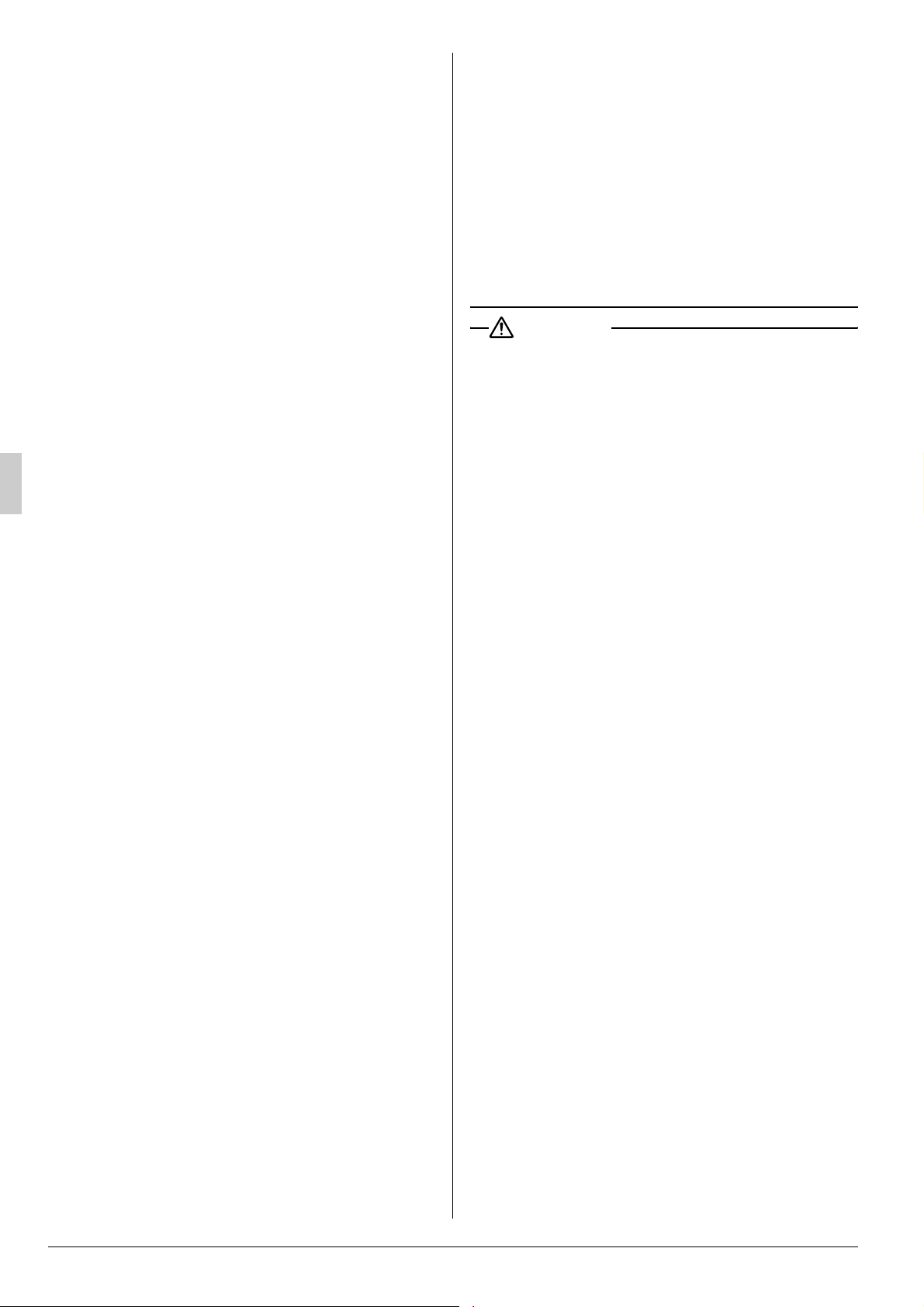
2-2 In the case of LCBKQ3AV1(E)
Power supply wires
(to dedicated earth
leakage breaker)
Earth wire
A wire that makes the system
safe by connecting the outdoor
unit to the ground for the
prevention of electric shocks
or fire resulting from electric
leakage.
Transmission
wiring
Refrigerant
piping
Do not attempt to conduct electrical work or
grounding work unless you are licensed to do
so.
Consult with your dealer for electrical work and
grounding work.
Check that the power supply is suitable to the
unit and that an exclusive circuit is provided to
the unit.
Check the electric capacity and voltage.
2. NAME OF PART
2-1
In the case of LRYEQ16AY1(E)
Air outlet
Fan
Air inlet
Heat exchanger
(aluminium fin)
Transmission
wiring
Refrigerant
piping
Earth wire
A wire that makes the system
safe by connecting the outdoor
unit to the ground for the
prevention of electric shocks
or fire resulting from electric
leakage.
Power supply wires
(to dedicated earth
leakage breaker)
3. WHAT TO DO BEFORE OPERATION
This operation manual is for the following system with standard control. Before initiating
operation, contact your Daikin dealer for the
operation that corresponds to your system type
and mark.
If your installation has a customized control
system, ask your Daikin dealer for the operation
that corresponds to your system.
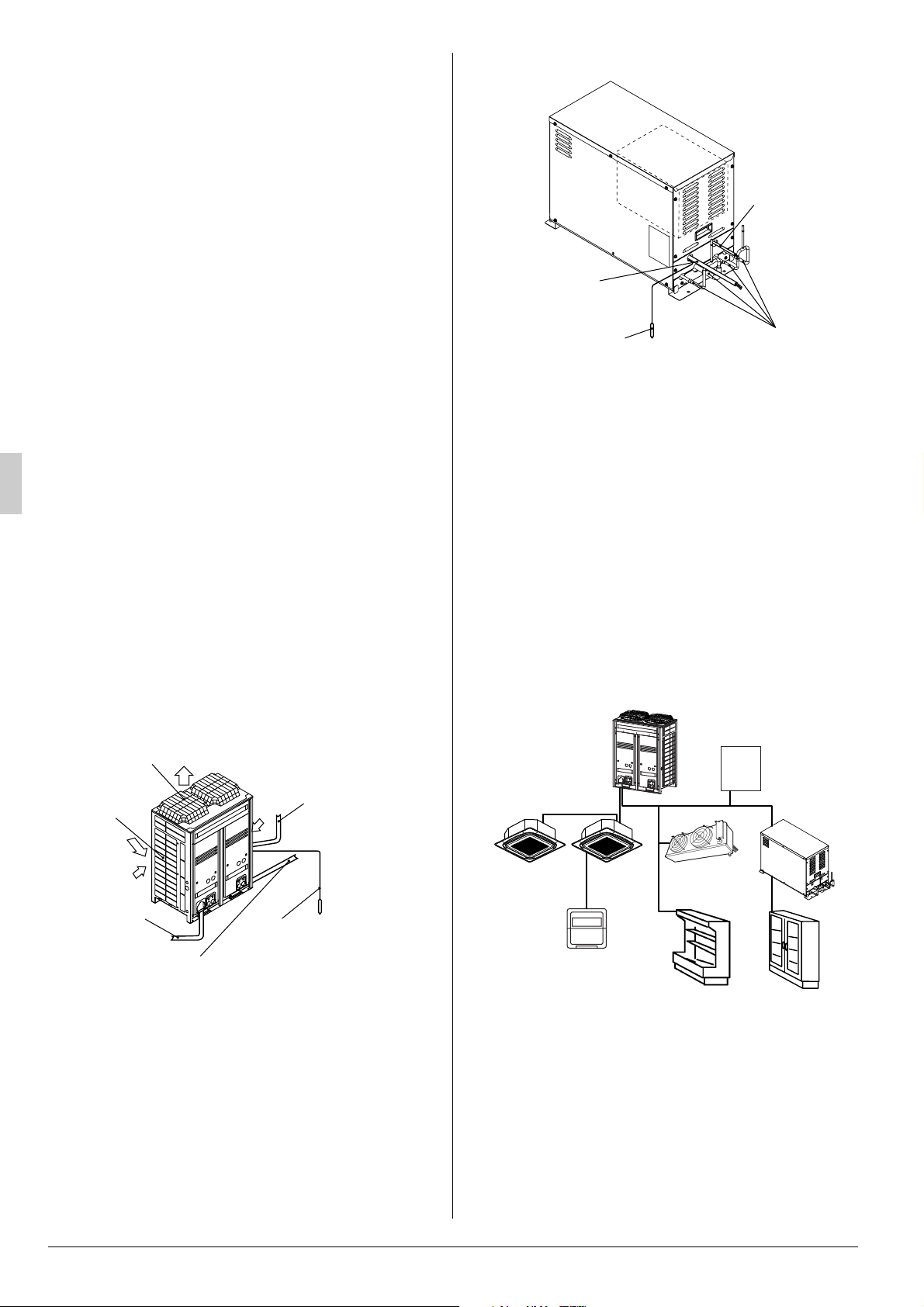
Example of connecting system
1
3
4
1 Outdoor unit
2 Booster unit
3 Indoor unit for air-conditioning
4 Remote controller
5 Blower coil (Indoor unit for refrigerating)
6 Showcase (Indoor unit for refrigerating)
7 Showcase (Indoor unit for freezing)
8 Defrost control panel
5
6
8
2
7
For the device except outdoor unit and booster unit,
refer to the Operation Manuals of the respective
pieces of equipment.
4 English
Page 7

4. REMOTE CONTROLLER AND
COOL/HEAT SELECTOR: NAME
AND FUNCTION OF EACH SWITCH
AND DISPLAY
Refer to the operation manual attached with the
remote controller if a remote controller is
BRC1E51A. (This manual assumes that a
remote controller is BRC1C62.)
Fig.1
1. On/off button
Press the button and the system will start. Press
the button again and the system will stop.
2. Operation lamp (red)
The lamp lights up during operation.
3.
Display
It is impossible to changeover heat/cool with the
remote controller which display this icon.
4. Display “ ” (air flow flap)
Refer to the chapter “Operation procedure Adjusting the air flow direction”.
5. Display “ ” (ventilation/air cleaning)
This display shows that the ventilation unit are in
operation. (these are optional accessories)
6. Display “ ” (set temperature)
This display shows the temperature you have
set.
7.Display “” “” “” “” “” (operation mode)
This display shows the current operation mode.
8. Display “ ” (programmed time)
This display shows the programmed time of the
system start or stop.
9. Display “ ” (inspection/test operation)
When the inspection/test operation button is
pressed, the display shows the mode in which
the system actually is.
“”
TEST
(changeover under control)
C
10.Display “ ” (under centralized control)
When this display shows, the system is under
centralized control. (This is not a standard specification.)
11.Display “ ” (fan speed)
This display shows the fan speed you have
selected.
12.Display “ ” (time to clean air filter)
Refer to the operation manual of indoor unit.
13.Display “ ” (defrost/hot start)
Refer to the chapter “Operation procedure Explanation of heating operation.”
14.Timer mode start/stop button
Refer to the chapter “Operation procedure - Programming start and stop of the system with
timer.”
15.Timer on/off button
Refer to the chapter “Operation procedure - Programming start and stop of the system with
timer.”
16.Inspection/test operation button
This button is only used by qualified service persons for maintenance purposes.
17.Programming time button
Use this button for setting the programming start
and/or stop time.
18.Temperature setting button
Use this button for setting the desired temperature.
19.Filter sign reset button
Refer to the operation manual of indoor unit.
20.Fan speed control button
Press this button to select the fan speed of your
preference.
21.Operation mode selector button
Press this button to select the operation mode of
your preference.
22.Air flow direction adjust button
Refer to the chapter “Operation procedure Adjusting the air flow direction”.
23.Fan only/air conditioning selector switch
Set the switch to “ ” for fan only operation or to
“ ” for heating or cooling operation.
24.Cool/heat changeover switch
Set the switch to “ ” for cooling operation or to
“ ” for heating operation.
25.Thermistor
It sense the room temperature around the
remote controller.
English 5
Page 8

26.These button are used when the ventilation
unit are installed (These are optional accessories)
Refer to the operation manual of the ventilation
unit.
NOTE
• In contradistinction to actual operating situations,
the display on figure 2 shows all possible indications.
• Figure 1 shows the remote controller which is
opened the cover.
5. OPERATION PROCEDURE
• Operation procedure varies according to the combination of outdoor unit and remote controller.
Read the chapter “What to do before operation”.
• To protect the unit, turn on the main power switch
6 hours before operation.
• And do not turn off the power supply during the air
conditioning season because of smoothly start
up.
• If the main power supply is turned off during operation, operation will restart automatically after the
power turns back on again.
5-1 COOLING, HEATING , AUTOMATIC AND
FAN ONLY OPERATION
• The fan may keep on running for about 1 minute
after the heating operation stops for removing the
heat in the indoor unit.
• The air flow rate may be adjusted automatically
depending on the room temperature or the fan
may stop immediately. This is not a malfunction.
• For machine protection the system may control
the air flow rate automatically.
• It may take sometime for finishing to change the
air flow rate.
This is normal operation.
ADJUSTMENT (Refer to Fig.2)
For adjustment the desired temperature, fan
speed and air flow direction (only for the
remote controller: FXC, FXF, FXH), follow the
procedure shown below.
Press the temperature setting button and set
3
the desired temperature.
Each time this button is pressed, the
temperature setting rises or lowers 1°C.
NOTE
• Set the temperature within the operation
range.
• The temperature setting is impossible for fan
only operation.
Press the fan speed control button and select
4
the fan speed of your preference.
Fig.2
Press the operation mode selector button sev-
1
eral times and select the operation mode of
your choice;
• “ ” Cooling operation
• “ ” Heating operation
• “ ” Fan only operation
Press the on/off button.
2
The operation lamp lights up and the system
starts operation.
• The operation mode cannot be changed with the
remote controller whose display shows
“ ” (changeover under control).
Change the operation mode with the remote controller whose display does not show “ ”.
• When the display “ ” (changeover under
control) flashes, refer to the chapter “Operation
procedure - Setting the master remote controller”.
Press air flow direction adjust button.
5
Refer to the chapter “Adjusting the air flow
direction” for details.
STOPPING THE SYSTEM (Refer to Fig.2)
Press the on/off button once again.
6
The operation lamp goes off and the system
stops operation.
NOTE
• Do not turn off the power immediately after
the unit stops.
• The system need at least 5 minutes for
residual operation of drain pump device.
Turning off the power immediately will cause
water leak or trouble.
EXPLANATION OF HEATING OPERATION
• For general heating operation, it may take longer
to reach the set temperature than in cooling operation.
We recommend starting the operation which was
used before using timer operation.
• The following operation is performed in order to
prevent the heating capacity from dropping or
cold air from blowing.
6 English
Page 9

Defrost operation
• In heating operation, freezing of the outdoor
unit heat exchanger increases. Heating
capability decreases and the system goes
into defrost operation.
• The indoor unit fan stops and the remote
controller displays “ ”.
• After maximum 10 minutes of defrost operation, the system returns to heating operation
again.
Hot start
• In order to prevent cold air from blowing out
of an indoor unit at the start of heating operation, the indoor fan is automatically
stopped. The display of the remote controller
shows “ ”.
NOTE
• The heating capacity drops as the outside temperature falls. If this happens, use another heating device together with the unit. (When using the
appliances which produce open fire together, ventilate a room constantly.)
Do not place appliances which produce open fire
in places exposed to the air flow from the unit or
under the unit.
• It takes some time for the room to warm up from
the time the unit is started since the unit uses a
hot-air circulatory system to warm the entire
room.
• If the hot air rises to the ceiling, leaving the area
above the floor cold, we recommend using the circulator (the indoor fan for circulating air). Contact
your dealer for details.
5-2 PROGRAM DRY OPERATION
• The function of this operation is to decrease the
humidity in your room with a minimum temperature decrease.
• The micro computer automatically determines
temperature and fan speed.
• The system does not go into operation if the room
temperature is low.
• The microcomputer automatically controls the
temperature and fan speed, so these cannot be
set using the remote controller.
• This function is not available if the room temperature is 20°C or lower.
Fig.3
Press the operation mode selector button sev-
1
eral times and select “ ” (program dry operation).
Press the on/off button.
2
The operation lamp lights up and the system
starts operation.
Press the air flow direction adjust button (only
3
for FXC, FXF, FXH). Refer to the chapter
“Adjusting the air flow direction” for details.
Press the on/off button once again.
4
The operation lamp goes off and the system
stops operation.
NOTE
• Do not turn off the power immediately after
the unit stops.
• The system need at least 5 minutes for
residual operation of drain pump device.
Turning off the power immediately will cause
water leak or trouble.
5-3 ADJUSTING THE AIR FLOW DIRECTION
(only for Double-flow, Multi-flow, Ceilingsuspended)
Fig.4
Press the air flow direction button to
1
select the air direction.
The air flow flap display swings as
shown right and the air flow direction
continuously varies. (Automatic swing
setting)
English 7
Page 10

Press the air flow direction adjust but-
2
ton to select the air direction of your
choice.
The air flow flap display stops swinging and the air flow direction is fixed.
(Fixed air flow direction setting)
MOVEMENT OF THE AIR FLOW FLAP
For the following conditions, a micro computer controls the air flow direction which may be different
from the display.
COOLING HEATING
• When starting operation.
• When the room temperature is
higher than the set temperature.
• At defrost operation.
• When operating continuously at horizontal air flow direction.
• When continuous operation with downward air flow is performed at the
time of cooling with a ceiling-suspended or a wall-mounted unit, the
micro-computer may control the flow direction, and then the remote control indication also will change.
The air flow direction can be adjusted in one of the
following ways.
• The air flow flap itself adjusts its position.
• The air flow direction can be fixed by the user.
Automatic “ ” or desired position “ ”.
5-4 PROGRAMMING START AND STOP OF
THE SYSTEM WITH TIMER
• The timer is operated in the following two ways.
Programming the stop time “ ”. The system
stops operating after the set time has elapsed.
Programming the start time “ ”. The system
starts operating after the set time has elapsed.
• The timer can be programmed for a maximum of
72 hours.
• The start and the stop time can be simultaneously
programmed.
Fig.6
Press the timer mode start/stop button several
1
times and select the mode on the display.
NOTE
• The movable limit of the flap is changeable.
Contact your Daikin dealer for details. (Only
for Double-flow, Multi-flow, Corner, Ceilingsuspended and Wall-mounted.)
• Avoid operating in the horizontal direction
“ ”. It may cause dew or dust to settle on
the ceiling.
Double-flow
Ceiling Suspended
Multi-flow
Fig.5
The display flashes.
• For setting the timer stop “ ”
• For setting the timer start “ ”
Press the programming time button and set
2
the time for stopping or starting the system.
Each time this button is pressed, the
time advances or goes backward by 1
hour.
Press the timer on/off button.
3
The timer setting procedure ends. The display
“ ” or “ ” changes from flashing
light to constant light.
NOTE
• When setting the timer off and on at the
same time, repeat the above procedure
(from “ ” to “ ”) once again.
1 2
• After the timer is programmed, the display
shows the remaining time.
• Press the timer on/off button once again to
cancel programming. The display vanishes.
8 English
Page 11

For example:
When the timer is programmed to stop the system after 3 hours and start the system after 4
hours, the system will stop after 3 hours and
start 1 hour later.
Fig.7
5-5 PRECAUTIONS FOR GROUP CON-
TROL SYSTEM OR TWO REMOTE CONTROLLER CONTROL SYSTEM
This system provides two other control systems
beside individual control (one remote controller controls one indoor unit) system. Confirm about your
system to Daikin dealer.
• Group control system
One remote controller controls up to 16 indoor
units. All indoor units are equally set.
• Two remote controller control system
Two remote controllers control one indoor unit (in
case of group control system, one group of indoor
units). The unit is individually operated.
NOTE
• Contact your Daikin dealer in case of changing the combination or setting of group control and two remote controller control
systems.
6. OPTIMUM OPERATION
Observe the following precautions to ensure the
system operates properly.
• Turn off the power if the unit is not operated for a
long time.
The unit will consume a power of several watts to
several tens of watts if the power is on (see note).
For the purpose of machine protection, however, be
sure to turn on the power at least 6 hours before
resuming the operation of the unit.
OFF
• Install an alarm if operational errors are likely to
degrade the commodities in storage.
The unit is provided with a terminal to output an
alarm signal.
If the system should malfunction and there is no
alarm, the operation of the unit will be interrupted for
a long time and damage to the commodities in storage may result.
The installation of an alarm is recommended in
order to take appropriate measures promptly in such
cases.
For details, consult your dealer.
• Adjust the air outlet properly and avoid direct air
flow to room inhabitants.
• Adjust the room temperature properly for a comfortable environment. Avoid excessive heating or
cooling.
• Prevent direct sunlight from entering a room during cooling operation by using curtains or blinds.
• Ventilate often.
Extended use requires special attention to ventilation.
• Do not keep doors and windows opened. If the
doors and windows remain open, air will flow out
of your room causing a decrease in the cooling or
heating effect.
• Never place objects near the air inlet or the air
outlet of the unit. It may cause deterioration in the
effect or stop the operation.
• Turn off the main power supply switch to the unit
when the unit is not used for longer periods of
time. If the switch is on, it uses electricity. Before
restarting the unit, turn on the main power supply
switch 6 hours before operation to ensure smooth
running. (Refer to the chapter “Maintenance” in
the indoor unit manual.)
• When the display shows “ ” (time to clean the
air filter), ask a qualified service person to clean
the filters. (Refer to the chapter “Maintenance” in
the indoor unit manual.)
• Keep the indoor unit and remote control at least 1
m away from televisions, radios, stereos, and
other similar equipment.
Failing to do so may cause static or distorted pictures.
• Do not use other heating devices directly beneath
the indoor unit.
If you do, they might get deformed by the heat.
• It takes time for the room temperature to reach the
set temperature.
We recommend starting the operation in advance
using timer operation.
Note: The power consumption of the unit varies with
the operating factors, such as the CONVENIPAC K mo d el .
English 9
Page 12

7. CARE AND CLEANING METHOD
Be sure to stop the operation of the unit with the
power switch and turn off the power (i.e., turn off
the earth leakage breaker) before starting the
maintenance of the unit.
CAUTION
Do not touch the aluminium fin directly at the
time of cleaning.
Doing so may result in injury.
Do not wash the unit with water.
Doing so may result in electric shock or ignition.
Be sure to stop the operation of the unit and
turn off the power circuit breaker at the time
of cleaning, maintenance and inspection.
Otherwise, electric shock or injury may result.
Cleaning the outdoor unit
• Consult your local dealer.
Cleaning the indoor unit
• As the system is an all-in-one air-conditioner and
refrigerator, the fan may rotate in a heating mode
even if operation is stopped with the remote controller.
Be sure to stop operation with the remote controller and cut off the power breaker before cleaning.
Refer to the operation manual attached to the
indoor unit for details.
Cleaning the showcase and the unit cooler
• Refer to the operation manual attached to the
showcase and the unit cooler for details.
Cleaning the drain pan (Optional accessory)
• Clean the drain pan so that it does not become
clogged and dusty.
• Turn off the power (i.e., turn off the earth leakage
breaker) if the unit is not used for a long time.
8. TROUBLESHOOTING
8-1 The following cases are not malfunc-
tions.
1. The unit does not operate.
• The air conditioner does not start immediately when restart the operation after stop
the operation or change operation mode
after set the operation mode.
If the operation lamp lights, the system is in
normal condition.
To prevent overloading of the compressor
motor, the air conditioner starts 5 minutes after
it is turned ON again in case it was turned OFF
just before.
• If “Centralized Control” is displayed on the
remote controller and pressing the operation button causes the display to blink for a
few seconds.
This indicates that the central device is controlling the unit.
The blinking display indicates that the remote
control cannot be used.
• The system does not start immediately
after the power supply is turned on.
Wait one minute until the micro computer is
prepared for operation.
2. It stops sometimes
• The remote controller display reads “U4” or
“U5” and stops but then restarts after a few
minutes.
This is because the remote control is intercepting noise from electrical appliances other than
the air conditioner, and this prevents communication between the units, causing them to stop.
Operation automatically restarts when the
noise goes away.
3. COOL/HEAT cannot be changed over.
• When the display shows “ ”
(changeover under control).
It shows that this is a slave remote controller.
Refer to “Setting the master remote controller”.
• When the cool/heat selector switch is
installed and the display shows
“ ” (changeover under control).
This is because cool/heat changeover is controlled by the cool/heat selector. Ask your
Daikin dealer where the remote control switch
is installed.
4. Fan operation is possible, but cooling and
heating do not work.
• Immediately after the power is turned on.
The micro computer is getting ready to operate.
Wait 10 minutes.
5. The fan strength does not correspond to the
setting.
• The fan strength does no change even if the
fan strength adjustment button in pressed.
During heating operation, when the room temperature reaches the set temperature, the outdoor unit goes off and the indoor unit changes
to whisper fan strength.
This is to prevent cold air blowing directly on
occupants of the room.
The fan strength will not change even if the button is changed, when another indoor unit is in
heating operation.
10 English
Page 13

6. White mist comes out of a unit.
<Indoor unit for air conditioning>
• When humidity is high during cooling operation.
If the interior of an indoor unit is extremely contaminated, the temperature distribution inside
a room becomes uneven. It is necessary to
clean the interior of the indoor unit. Ask your
Daikin dealer for details on cleaning the unit.
This operation requires a qualified service person.
• Immediately after the cooling operation
stops and if the room temperature and
humidity are low.
This is because warm refrigerant gas flows
back into the indoor unit and generates steam.
<Indoor unit for air-conditioning, outdoor
unit>
• When the system is changed over to heating operation after defrost operation.
Moisture generated by defrost becomes steam
and is exhausted.
7. Noise of air-conditioners.
<Indoor unit for air-conditioning>
• A continuous low “shah” sound is heard
when the system is in cooling operation or
at a stop.
When the drain pump (optional accessories) is
in operation, this noise is heard.
• A low “sah”, “choro-choro” sound is heard
while the indoor unit is stopped.
When the other indoor unit is in operation, this
noise is heard. In order to prevent oil and
refrigerant from remaining in the system, a
small amount of refrigerant is kept flowing.
<Outdoor unit, booster unit>
• When the tone of operating noise changes.
This noise is caused by the change of frequency.
<Indoor unit for air-conditioning, outdoor
unit, booster unit>
• A continuous low hissing sound is heard
when the system is in cooling or defrost
operation.
This is the sound of refrigerant gas flowing
through both indoor and outdoor units.
• A hissing sound which is heard at the start
or immediately after stopping operation or
defrost operation.
This is the noise of refrigerant caused by flow
stop or flow change.
8. Dust comes out of the unit.
• When the unit is used after stopping for a
long time.
This is because dust has gotten into the unit.
9. The units can give off odours.
• During operation.
The unit can absorb the smell of rooms, furniture, cigarettes, etc., and then emit it again.
10.The outdoor unit fan does not spin.
• During operation.
The speed of the fan is controlled in order to
optimize product operation.
11.The display shows “ ”
• This is the case immediately after the main
power supply switch is turned on.
This means that the remote controller is in normal condition. This continues for one minute.
12.The compressor or fan in the outdoor unit
does not stop.
• This is to prevent oil and refrigerant from
remaining in the compressor. The unit will
stop after 5 to 10 minutes.
13.Hot air is emitted even though the unit is
stopped.
• Hot air can be felt when the unit is stopped.
Several different indoor units are being run on
the same system, so if another unit is running,
some refrigerant will still flow through the unit.
14.Does not cool very well.
• Program dry operation.
Program dry operation is designed to lower the
room temperature as little as possible.
Refer to page 7.
15.The indoor fan may rotate while the unit
stops.
• The fan rotates even if the operation is
stopped with the remote controller.
As the system operates as an all-in-one airconditioner and refrigerator, the fan works to
prevent oil and refrigerant from accumulating
on the air conditioner during operation of the
showcase.
8-2 Check before Requesting Servicing.
1. The unit does not operate at all.
• Has the power supply fuse not blown out?
Turn off the power. (Consult your dealer for the
replacement of the power supply fuse.)
• Is the power circuit breaker not turned off?
Turn on the power if the knob of the power circuit breaker is set to the OFF position.
Do not turn on the
power if the knob of
the power circuit
breaker is set to the
trip position. (Consult
your dealer.)
Breaker
ON
OFF
Switch
Trip position
English 11
Page 14

• Is there no blackout?
Wait until power is restored. If power failure
occurs during operation, the system automatically restarts immediately after the power supply is recovered.
• Are all the power supplies turned on?
Turn all the power on.
2. The unit comes to a stop soon after the unit
starts operating.
• Do obstacles not block the air inlet or outlet of
the outdoor unit or indoor unit?
Remove the obstacles.
• Check if the remote controller display shows
“ ” (time to clean the air filter);
Refer to the operation manual of the indoor unit
for air-conditioning. And clean the air filter.
3. The system operates but cooling or heating
is insufficient (Air-conditioning).
• Check if air inlet or outlet of outdoor or indoor
unit is not blocked by obstacles.
Remove any obstacle and make it well-ventilated.
• Check if the remote controller display shows
“ ” (time to clean the air filter);
Refer to the operation manual of the indoor unit.
And clean the air filter.
• Check the temperature setting.
Refer to “Operation procedure”.
• Check the fan speed setting on your remote
controller.
Refer to “Operation procedure”.
• Check for open doors or windows.
Shut doors and windows to prevent wind from
coming in.
• Check if there are too many occupants in the
room during cooling operation.
• Check if the heat source of the room is excessive during cooling operation.
• Check if direct sunlight enters the room during
cooling operation.
Use curtains or blinds.
• Check if the air flow angle is not proper.
Refer to “Operation procedure”.
4. The cooling operation of the unit is bad.
• Does the indoor unit (unit cooler and showcase) not have much frost?
Defrost manually or shorten the cycle of
defrosting operation.
• Are there not too many articles inside?
Reduce the number of articles.
• Is the circulation of cold air in the indoor unit
(unit cooler and showcase) smooth?
Change the allocation of the articles.
• Is there not much dust on the heat exchanger of
the outdoor unit?
Remove the dust with a brush or vacuum
cleaner without using water or consult your
dealer.
• Is cold air not leaking outside?
Stop the leakage of cold air.
• Is the set temperature in the indoor unit (unit
cooler and showcase) not too high?
Set the temperature appropriately.
• Are high-temperature articles not stored?
Store them after they are once cooled off.
• Is the opening time of the door not long?
Minimize the opening time of the door.
8-3 Consult your dealer in the following
cases.
WARNING
When the CONVENI-PACK is malfunctioning
(giving off a burning odour, etc.) turn off
power to the unit and contact your local
dealer.
Continued operation under such circumstances
may result in a failure, electric shocks or fire hazards.
1. Safety devices, such as the fuse, breaker, and
earth leakage breaker, frequently operate or
the operation of the RUN switch is not stable.
Contact your dealer after turning the power off.
2. Turn off the power and consult your dealer if
symptoms other than the above are noticed
or the equipment does not go into normal
operation after taking the steps specified in
8-2.
9. INSPECTION
The preventive maintenance of the unit is
required in order not to damage commercial
products. Request a contractor authorized by
our dealer for inspection.
Refer to information on maintenance inspection on
page 14 for maintenance inspection.
12 English
Page 15

10. PRODUCT MODELS AND MAIN SPECIFICATIONS
10-1Models and Main Specifications.
Model LRYEQ16AY1 (E) LCBKQ3AV1 (E)
Power supply 3 phase 380~415V 50Hz 1 phase 220~240V 50Hz
Refrigerant R410A
Operating condition
Capacity (kW)
Outer dimensions (HxWxD) (mm) 1680×1240×765 480×680×310
Product mass (kg) 370 47
Sound pressure level (dB(A)) 62 49
Design pressure
Note:
• Operating conditions:
Outdoor unit
(Air-conditioning side) Indoor temperature: 27ºCDB/19ºCWB, Outdoor temperature: 32ºCDB, Piping
length: 7.5m, Level difference: 0m (In cooling priority mode)
(Cooling equipment side) Evaporating temperature: -10ºC, Outdoor temperature: 32ºCDB, Suction SH:
10ºC (In cooling priority mode)
(Heating conditions)Indoor temperature: 20ºCDB, Outdoor temperature: 7ºCDB/6ºCWB, Cooling equipment load: 18 kW,
Piping length: 7.5 m, Level difference: 0 m
Saturated temperature equivalent to suction pressure (Cooling equipment side) : -10ºC (Under chilled condition),
Connection capacity for indoor air-conditioner: 10HP, When heat recovery is 100%
Evaporating temperature -20ºC~10ºC (Refrigeration) -45ºC~-20ºC
Refrigeration -15ºC~43ºCDB
Outdoor
temperature
Cool
Heat
High-pressure
side
Low-pressure
side
Cool -5ºC~43ºCDB
Heat
Air-conditioning 14 -
Refrigerating 21.8 -
Free zing - 3.35
Air-conditioning 27 -
Refrigerating 21.8 -
Free zing - 3.35
(bar) 38 38
(MPa) 3.8 3.8
(bar) 25 25
(MPa) 2.5 2.5
-15ºC~21ºCDB
-15ºC~15.5ºCWB
-15ºC~43ºCDB
Booster unit
Evaporating temperature: -35ºC, Outdoor temperature: 32ºC, Suction SH: 10ºC, Saturated temperature to
discharge pressure of booster unit: -10ºC
• The figures for the outside unit models show values measured at a distance of 1 m in the front and a height
of 1.5 m.
Values measured with the models actually installed are usually larger then the values shown as a result of
ambient noise and reflections.
When the outdoor temperature is low, the temperature reading may be below the target evaporating temperature set for the protection of the unit.
• Values are subject to change without notice for product improvements.
• The "E" suffix indicates anti-corrosion models.
English 13
Page 16

11. AFTER-SALE SERVICE AND
WARRANTY
11-1 After-sale Service
WARNING
Consult your local dealer regarding modification, repair and maintenance of the CONVENI-PACK.
Improper workmanship may result in water leakage, electric shocks or fire hazards.
Consult your local dealer regarding relocation
and reinstallation of the CONVENI-PACK.
Improper installation work may result in leakage,
electric shocks or fire hazards.
Beware of fire in case of refrigerant leakage.
If the CONVENI-PACK is not operating correctly
(i.e. the interior temperature of the CONVENIPACK does not drop efficiently), refrigerant leakage could be the cause.
Consult your dealer for assistance.
The refrigerant within the CONVENI-PACK is safe
and normally does not leak.
However, in the event of a leakage, contact with a
naked burner, heater or cooker may result in generation of noxious gas.
Do not longer use the CONVENI-PACK until a
qualified service person confirms that the leakage
has been repaired.
4. Relocation and Disposal
• Contact your dealer for removing and reinstalling the system CONVENI-PACK since they
require technical expertise.
• The system CONVENI-PACK uses fluorocarbon refrigerant.
Contact your dealer for discarding the system
CONVENI-PACK since it is required by law to
collect, transport and discard the refrigerant in
accordance with relevant local and national
regulations.
• In either case, consult your dealer.
5. Inquiries
Contact your dealer for after-sale services.
11-2 Warranty Card
1. This product comes with a warranty card.
Your dealer will deliver you the warranty card
filled out with the necessary items. Check the
details and have the administrative person in
charge of the heat source unit for refrigeration
system keep the warranty card carefully.
2. When requesting repairs for free during the warranty period, contact your dealer and be sure to
present the warranty card.
Repair services may be charged during the warranty period if the warranty card is not presented.
Be sure to keep the warranty card carefully.
1. Inform your dealer of the following items
when you request repairs.
• Model name Described in the warranty card.
• Serial number and date of installation
Described in the warranty card.
• Defective condition
• Your address, name, and telephone number
2. Repairs after Expiration of Warranty Period
Consult your dealer. Onerous repairs will be possible if the unit can maintain its original functions
after the repairs are made.
3. Maintenance Inspection
The interior of the refrigeration CONVENI-PACK
will become dirty and its performance may be
degraded if it is used for several seasons.
The disassembly and internal cleaning of the unit
requires specialized techniques. Therefore, our
dealer recommends an onerous maintenance
inspection besides usual maintenance services.
For details, consult your dealer.
Keep in mind that our dealer’s warranty may not
cover malfunctions resulting from the disassembly or internal cleaning of the unit conducted by
contractors not authorized by our dealer.
–
as precise as possible
Warranty period: 1 year counting from the date
of installation.
For details, read through the warranty card.
3. Secondary Warranties
Our dealer will not provide secondary warranties,
such as compensation for chilled product damage or business loss, resulting from failures in
the product.
Perform regular temperature control if secondary
disaster is feared. Besides, consult your dealer
and take appropriate measures, such as the
installation of an alarm system or auxiliary equipment.
In addition, take out accident insurance.
14 English
Page 17

11-3 Onerous Repairs (Outside Scope of
Warranty Coverage)
11-3-1 Accidents Resulting from Use
beyond Standards for Use
• Use beyond Limits
• Applications other than its designed purpose of
use or modification.
Standards for Use
Standards for Use
Item
Power supply Voltage
fluctuation
Outdoor temperature
range (Cool)
Outdoor temperature
range (Heat)
Connecting piping
length
Height difference
between inside and
outside units
Height difference
between outside unit
and booster unit
Height difference
between inside units
(Air-condition side)
Height difference
between inside units
(Showcase side)
Outdoor unit Booster unit
Within ±10% of rated voltage
ºC~
+43ºCDB
-5
ºC~21ºC
ºC~
15.5ºCWB
DB
-15
-15
Within 130 m
(Piping length
between Indoor and
Outdoor unit)
Within 35 m
(within 10 m if the out-
side unit is lower)
Within 35 m (within 10 m if the outside unit is
lower)
Within 0.5 m
Within 5 m
-15
ºC
~+43ºCDB
Within 30 m
(Piping length
between Indoor and
Booster unit)
Within 10 m
(within 0 m if the
booster unit is lower)
11-3-2 Selection, Installation, Work Failures
Specified below and Other Failures
Note: Asterisk-marked items show concrete exam-
ples.
1. Model selection failures
• A model not suitable for storage applications is
selected.
∗ The cooling of products not reaching the tar-
get storage temperatures.
• Cooling overloading or underloading judged by
our dealer.
∗ The frequency of stoppage is 6 or more times
per hour or the set cooling temperature is not
attained.
2. Installation failure (Installation and environmental problems)
• The unit is not installed on a stable horizontal
plane.
∗ The unit is not fixed securely.
• The environmental conditions of the place of
installation differ from normal atmospheric conditions.
∗ Briny air environment, shore side, oil mist
environment, kitchen exhaust side, other corrosive gas and adhesive mist environment.
• The place of installation had poor ventilation
and heat dissipation.
∗ The machine took in exhausted air again.
3. Work failure
• The interior of the piping was not vacuum dried
sufficiently.
∗ The clogging of the thin areas of the piping
caused by icing.
• The interior of the piping was not sufficiently airtight.
∗ Leakage of refrigerant gas.
• The interior of the piping was contaminated
with foreign substance.
∗ The clogging of the thin areas of the piping.
• The unit was adversely affected by on-site
modification work.
∗
The use of the unit beyond the operating temperature range as a result of on-site modification.
• An accident resulted from the improper handling of the unit under installation work.
∗ The loosening or wobbling of the outer panel
or broken or bent damage to the piping.
4. Operational failure
• Temperature settings for stored objects were
wrong.
∗ The storage of vegetables at temperatures
below 0°C.
• The periodical maintenance of the unit was
neglected.
∗ The clogging of the air heat exchanger, rust
generation from each part, gas leakage, and
icing of the indoor unit (showcase and unit
cooler).
5. Others
• Improvements recommended by our dealer in
advance were not accomplished.
∗ The simultaneous starting and stopping of a
number of units.
• Accidents were caused by natural disaster or
fire.
∗
Damage to electrical parts caused by lightning.
• There were other installation and operational
problems beyond common sense.
∗ The use of the unit without heat insulation
work on the piping.
• Work was conducted without keeping the following showcase restrictions.
<Showcase restrictions>
· The design pressure for the indoor unit is 2.5
MPa or more.
· The installation of the thermostatic expansion
valve and liquid supply solenoid valve (both of
which are for R410A) on a showcase basis.
Thermal insulation of feeler tube of thermostatic expansion valve must be thermal insulated.
·
Install showcases on the same floor if the showcases are connected to a single outdoor unit.
English 15
Page 18

· Make sure that the outlet of piping used for
the heat exchanger is located downward (as
shown on the following figure).
Inlet
(upper side)
Outlet
Heat exchanger
(lower side)
16 English
Page 19

3P248411-3B EM09A054
(1002) FS
 Loading...