

Page 1
Installation and operation
manual
Air-cooled refrigeration condensing unit
LRMEQ3AY1
LRMEQ4AY1
Installation and operation manual
Air-cooled refrigeration condensing unit
English
Page 2
1+2
1
A~E
a b c d e e
B
e
D
HBHDH
U
(mm)
a
b
c
d
e
e
B
e
D
A
B
C
D
E
H
B
H
U
H
D
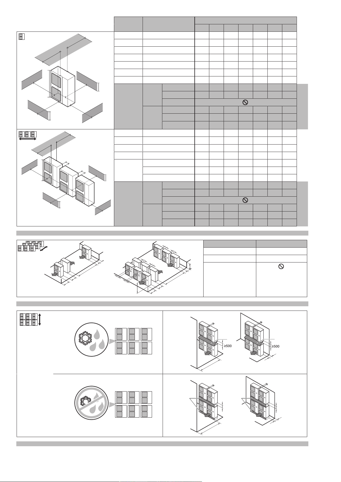
B — ≥100
A, B, C — ≥100 ≥100 ≥100
B, E — ≥100 ≥1000 ≤500
A, B, C, E — ≥150 ≥150 ≥150 ≥1000 ≤500
D — ≥500
D, E — ≥1000 ≥1000 ≤500
B, D — ≥100 ≥500
B, D, E HB<HDHB≤½H
U
≥250 ≥750 ≥1000 ≤500
½HU<HB≤H
U
≥250 ≥1000 ≥1000 ≤500
HB>H
U
HB>HDHD≤½H
U
≥100 ≥1000 ≥1000 ≤500
½HU<HD≤H
U
≥200 ≥1000 ≥1000 ≤500
HD>H
U
≥200 ≥1700 ≥1000 ≤500
H
U
a
b
≥100
≥100
c
d
e
e
B
e
D
A
B
C
D
E
H
B
H
D
A, B, C — ≥200 ≥300 ≥1000
A, B, C, E — ≥200 ≥300 ≥1000 ≥1000 ≤500
D — ≥1000
D, E — ≥1000 ≥1000 ≤500
B, D HD>H
U
≥300 ≥1000
HD≤½H
U
≥250 ≥1500
½HU<HD≤H
U
≥300 ≥1500
B, D, E HB<HDHB≤½H
U
≥300 ≥1000 ≥1000 ≤500
½HU<HB≤H
U
≥300 ≥1250 ≥1000 ≤500
HB>H
U
HB>HDHD≤½H
U
≥250 ≥1500 ≥1000 ≤500
½HU<HD≤H
U
≥300 ≥1500 ≥1000 ≤500
HD>H
U
≥300 ≥2200 ≥1000 ≤500
1
b (mm)
HB≤½H
U
b≥250
½HU<HB≤H
U
b≥300
HB>H
U
HBH
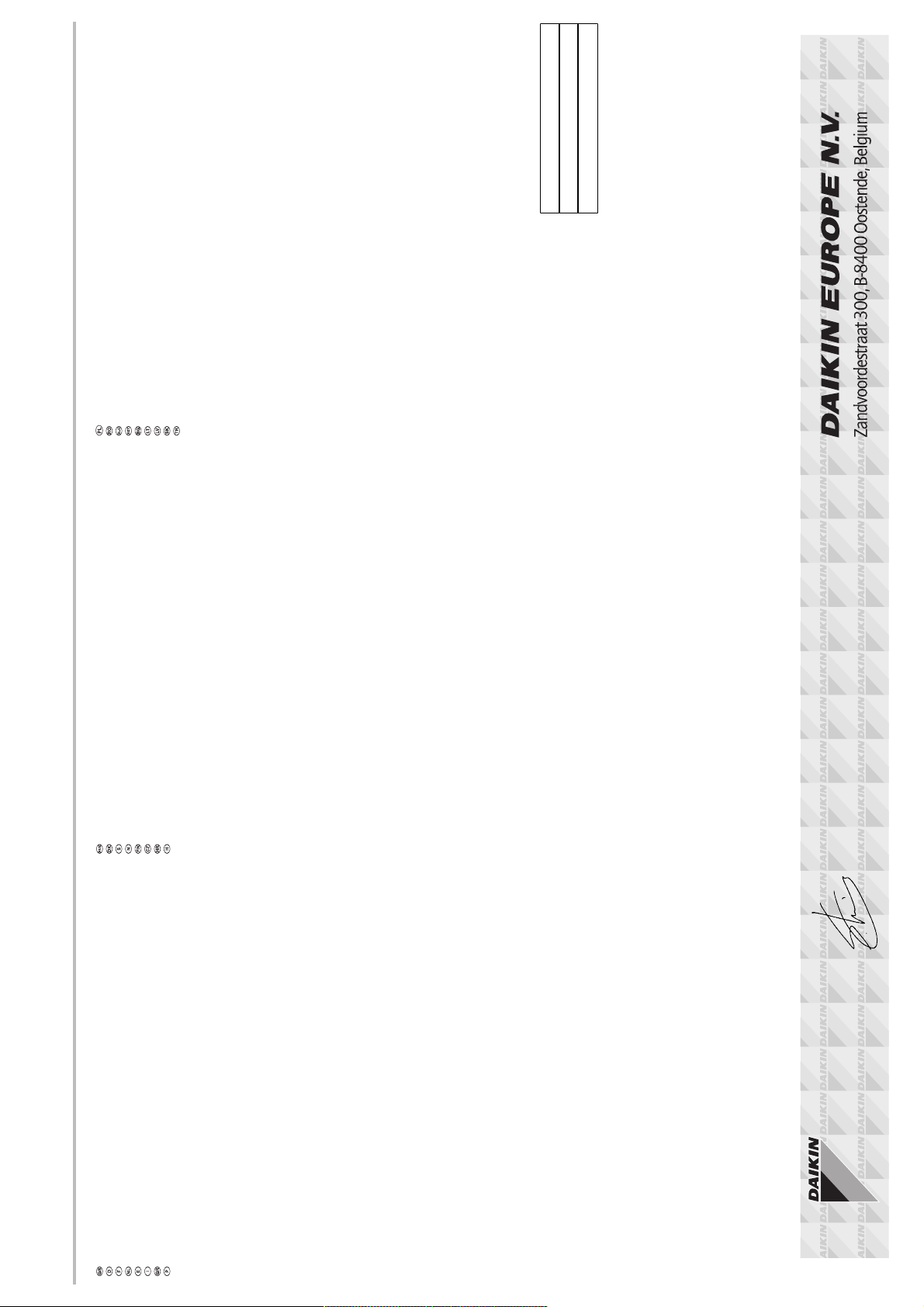
U
≥1000
≥200
≥2000
≥100
≥3000
≥600
≥1500
b
≥100
≥100
≥100
≥100
≥100
≥100
H
B
H
U
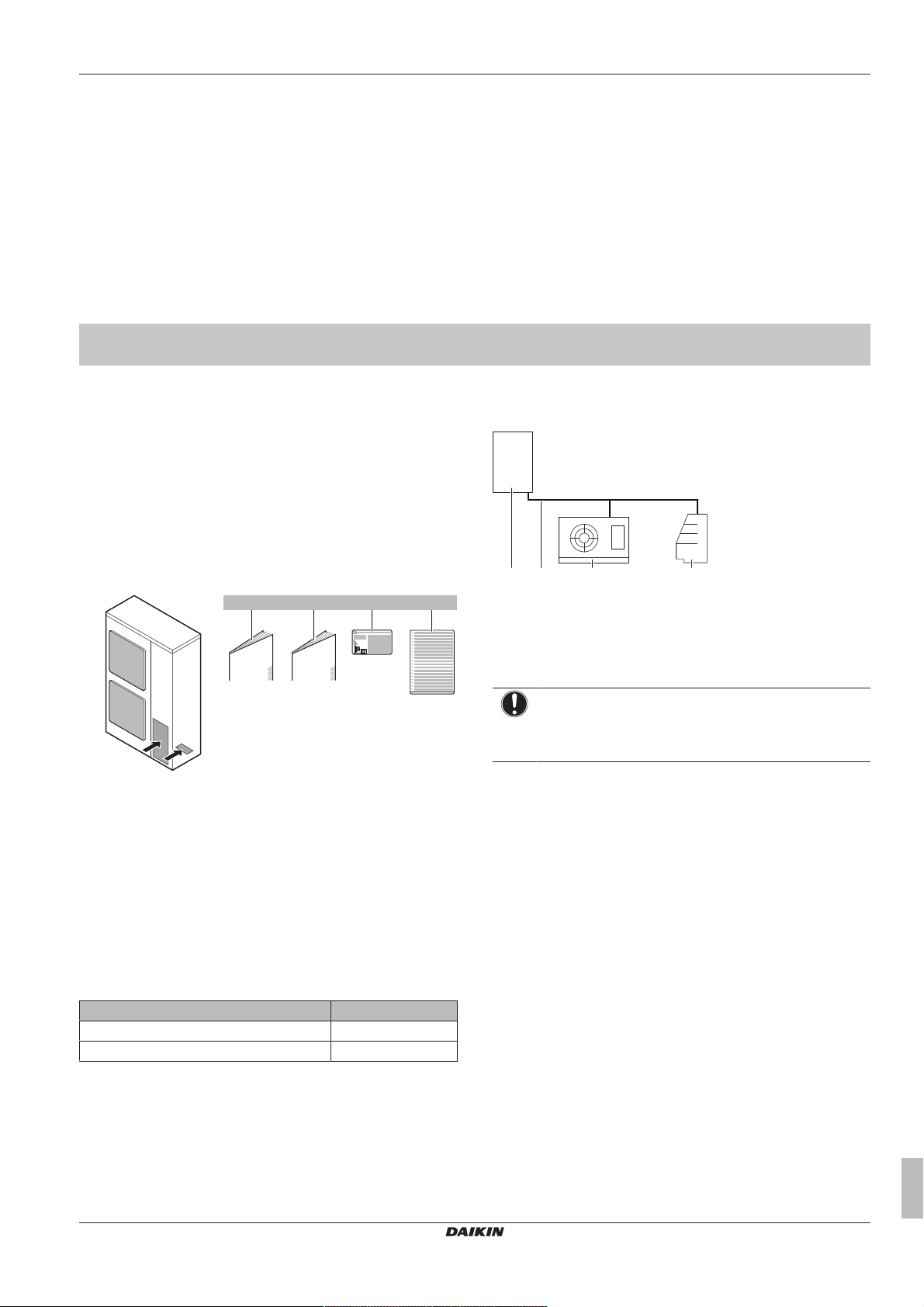
2
A1
B1
A2
B2
A2
≥1000
A2
≥300
≥100
≥100
≥100
≥300
≥100
≥100
B2
≥100
≥1000
B2
3
Page 3
Directivelor, cu amendamentele respective.
<A>
<B>
<C>
TÜV (NB1856)
502240101
DAIKIN.TCF.023C18/02-2016
Direktive z vsemi spremembami.
Direktiivid koos muudatustega.
Директиви, с техните изменения.
Direktyvose su papildymais.
Direktīvās un to papildinājumos.
Smernice, v platnom znení.
18192021222324
Direktiver, med senere ændringer.
Direktiv, med företagna ändringar.
Direktiver, med foretatte endringer.
10111213141516
deklaruje na własną i wyłączną odpowiedzialność, że modele klimatyzatorów, których dotyczy niniejsza deklaracja:
declară pe proprie răspundere că aparatele de aer condiţionat la care se referă această declaraţie:
z vso odgovornostjo izjavlja, da so modeli klimatskih naprav, na katere se izjava nanaša:
kinnitab oma täielikul vastutusel, et käesoleva deklaratsiooni alla kuuluvad kliimaseadmete mudelid:
декларира на своя отговорност, че моделите климатична инсталация, за които се отнася тази декларация:
visiška savo atsakomybe skelbia, kad oro kondicionavimo prietaisų modeliai, kuriems yra taikoma ši deklaracija:
ar pilnu atbildību apliecina, ka tālāk uzskaitīto modeļu gaisa kondicionētāji, uz kuriem attiecas šī deklarācija:
vyhlasuje na vlastnú zodpovednosť, že tieto klimatizačné modely, na ktoré sa vzťahuje toto vyhlásenie:
tamamen kendi sorumluluǧunda olmak üzere bu bildirinin ilgili olduǧu klima modellerinin aşaǧıdaki gibi olduǧunu beyan eder:
17
18
19
20
21
22
23
24
25
megfelelnek az alábbi szabvány(ok)nak vagy egyéb irányadó dokumentum(ok)nak, ha azokat előírás szerint használják:
spełniają wymogi następujących norm i innych dokumentów normalizacyjnych, pod warunkiem że używane są zgodnie z naszymi instrukcjami:
sunt în conformitate cu următorul (următoarele) standard(e) sau alt(e) document(e) normativ(e), cu condiţia ca acestea să fie utilizate în conformitate cu
instrucţiunile noastre:
skladni z naslednjimi standardi in drugimi normativi, pod pogojem, da se uporabljajo v skladu z našimi navodili:
on vastavuses järgmis(t)e standardi(te)ga või teiste normatiivsete dokumentidega, kui neid kasutatakse vastavalt meie juhenditele:
съответстват на следните стандарти или други нормативни документи, при условие, че се използват съгласно нашите инструкции:
atitinka žemiau nurodytus standartus ir (arba) kitus norminius dokumentus su sąlyga, kad yra naudojami pagal mūsų nurodymus:
tad, ja lietoti atbilstoši ražotāja norādījumiem, atbilst sekojošiem standartiem un citiem normatīviem dokumentiem:
sú v zhode s nasledovnou(ými) normou(ami) alebo iným(i) normatívnym(i) dokumentom(ami), za predpokladu, že sa používajú v súlade snašim
161718192021222324
návodom:
Directives, as amended.
Direktiven, gemäß Änderung.
ürünün, talimatlarımıza göre kullanılması koşuluyla aşağıdaki standartlar ve norm belirten belgelerle uyumludur:
25
Directives, telles que modifiées.
010203040506070809
**
Değiştirilmiş halleriyle Yönetmelikler.
25
Direktiivejä, sellaisina kuin ne ovat
muutettuina.
v platném znění.
Smjernice, kako je izmijenjeno.
irányelv(ek) és módosításaik rendelkezéseit.
z późniejszymi poprawkami.
17
както е изложено в <A> и оценено положително от <B>
съгласно Сертификата<C>.
kaip nustatyta <A> ir kaip teigiamai nuspręsta <B> pagal
Sertifikatą<C>.
kā norādīts <A> un atbilstoši <B> pozitīvajam vērtējumam
saskaņā ar sertifikātu<C>.
Richtlijnen, zoals geamendeerd.
Directivas, según lo enmendado.
Direttive, come da modifica.
Οδηγιών, όπως έχουν τροποποιηθεί.
Directivas, conforme alteração em.
Директив со всеми поправками.
21Забележка*
22Pastaba*
23Piezīmes*
*
Daikin Europe N.V. je pooblaščen za sestavo datoteke s tehnično mapo.
Daikin Europe N.V. on volitatud koostama tehnilist dokumentatsiooni.
Daikin Europe N.V. е оторизирана да състави Акта за техническа конструкция.
Daikin Europe N.V. yra įgaliota sudaryti šį techninės konstrukcijos failą.
Daikin Europe N.V. ir autorizēts sastādīt tehnisko dokumentāciju.
Spoločnosť Daikin Europe N.V. je oprávnená vytvoriť súbor technickej konštrukcie.
Daikin Europe N.V. Teknik Yapı Dosyasını derlemeye yetkilidir.
19**
20**
21**
22**
23**
24**
25**
ako bolo uvedené v <A> a pozitívne zistené <B> vsúlade
s osvedčením<C>.
<A>’da belirtildiği gibi ve <C>Sertifikasına göre <B>
tarafından olumlu olarak değerlendirildiği gibi.
24Poznámka*
25Not*
a(z) <A> alapján, a(z) <B> igazolta a megfelelést, a(z)
<C>tanúsítvány szerint.
zgodnie z dokumentacją <A>, pozytywną
opinią <B> i Świadectwem<C>.
aşa cum este stabilit în <A> şi apreciat pozitiv de<B>
în conformitate cu Certificatul<C>.
kot je določeno v <A> in odobreno s strani <B>
vskladu scertifikatom<C>.
nagu on näidatud dokumendis <A> ja heaks kiidetud
<B> järgi vastavalt sertifikaadile<C>.
Daikin Europe N.V. on valtuutettu laatimaan Teknisen asiakirjan.
Společnost Daikin Europe N.V. má oprávnění ke kompilaci souboru technické konstrukce.
Daikin Europe N.V. je ovlašten za izradu Datoteke o tehničkoj konstrukciji.
A Daikin Europe N.V. jogosult a műszaki konstrukciós dokumentáció összeállítására.
Daikin Europe N.V. ma upoważnienie do zbierania i opracowywania dokumentacji konstrukcyjnej.
13**
14**
15**
16**
16Megjegyzés*
17Uwaga*
18Notă*
19Opomba*
20Märkus*
17**
Machinery 2006/42/EC
enligt <A> och godkänts av <B> enligt
Certifikatet<C>.
som det fremkommer i <A> og gjennom positiv
bedømmelse av <B> ifølge Sertifikat<C>.
jotka on esitetty asiakirjassa <A> ja jotka <B>
on hyväksynyt Sertifikaatin<C> mukaisesti.
jak bylo uvedeno v <A> a pozitivně zjištěno
<B> vsouladu sosvědčením<C>.
kako je izloženo u <A> i pozitivno ocijenjeno odstrane
Electromagnetic Compatibility 2014/30/EU
заявляет, исключительно под свою ответственность, что модели кондиционеров воздуха, к которым относится настоящее заявление:
erklærer under eneansvar, at klimaanlægmodellerne, som denne deklaration vedrører:
deklarerar i egenskap av huvudansvarig, att luftkonditioneringsmodellerna som berörs av denna deklaration innebär att:
erklærer et fullstendig ansvar for at de luftkondisjoneringsmodeller som berøres av denne deklarasjon, innebærer at:
ilmoittaa yksinomaan omalla vastuullaan, että tämän ilmoituksen tarkoittamat ilmastointilaitteiden mallit:
prohlašuje ve své plné odpovědnosti, že modely klimatizace, k nimž se toto prohlášení vztahuje:
izjavljuje pod isključivo vlastitom odgovornošću da su modeli klima uređaja na koje se ova izjava odnosi:
teljes felelőssége tudatában kijelenti, hogy a klímaberendezés modellek, melyekre e nyilatkozat vonatkozik:
09
10
11
12
13
14
15
16
estão em conformidade com a(s) seguinte(s) norma(s) ou outro(s) documento(s) normativo(s), desde que estes sejam utilizados de
acordo com as nossas instruções:
соответствуют следующим стандартам или другим нормативным документам, при условии их использования согласно нашим инструкциям:
overholder følgende standard(er) eller andet/andre retningsgivende dokument(er), forudsat at disse anvendes i henhold til vore instrukser:
respektive utrustning är utförd i överensstämmelse med och följer följande standard(er) eller andra normgivande dokument, under förutsättning att
användning sker i överensstämmelse med våra instruktioner:
respektive utstyr er i overensstemmelse med følgende standard(er) eller andre normgivende dokument(er), under forutssetning av at disse brukes i
henhold til våre instrukser:
vastaavat seuraavien standardien ja muiden ohjeellisten dokumenttien vaatimuksia edellyttäen, että niitä käytetään ohjeidemme mukaisesti:
za předpokladu, že jsou využívány v souladu s našimi pokyny, odpovídají následujícím normám nebo normativním dokumentům:
08091011121314
u skladu sa slijedećim standardom(ima) ili drugim normativnim dokumentom(ima), uz uvjet da se oni koriste u skladu s našim uputama:
15
ob upoštevanju določb:
vastavalt nõuetele:
следвайки клаузите на:
laikantis nuostatų, pateikiamų:
ievērojot prasības, kas noteiktas:
19202122232425
održiavajúc ustanovenia:
11Information*
12Merk*
13Huom*
bunun koşullarına uygun olarak:
delineato nel <A> e giudicato positivamente da<B>
secondo il Certificato<C>.
όπως καθορίζεται στο <A> και κρίνεται θετικά
από το <B> σύμφωνα με το Πιστοποιητικό<C>.
tal como estabelecido em <A> e com o parecer positivo
<B> prema Certifikatu<C>.
14Poznámka*
15Napomena*
Η Daikin Europe N.V. είναι εξουσιοδοτημένη να συντάξει τον Τεχνικό φάκελο κατασκευής.
A Daikin Europe N.V. está autorizada a compilar a documentação técnica de fabrico.
Компания Daikin Europe N.V. уполномочена составить Комплект технической документации.
Daikin Europe N.V. er autoriseret til at udarbejde de tekniske konstruktionsdata.
Daikin Europe N.V. är bemyndigade att sammanställa den tekniska konstruktionsfilen.
07**
08**
09**
10**
11**
de <B> de acordo com o Certificado<C>.
как указано в <A> и в соответствии сположительным
решением <B> согласно Свидетельству<C>.
som anført i <A> og positivt vurderet af <B> ihenhold til
Certifikat<C>.
Daikin Europe N.V. este autorizat să compileze Dosarul tehnic de construcţie.
18**
Shigeki Morita
Director
Ostend, 1st of April, 2016
Daikin Europe N.V. har tillatelse til å kompilere den Tekniske konstruksjonsfilen.
12**
declares under its sole responsibility that the air conditioning models to which this declaration relates:
erklärt auf seine alleinige Verantwortung daß die Modelle der Klimageräte für die diese Erklärung bestimmt ist:
déclare sous sa seule responsabilité que les appareils d'air conditionné visés par la présente déclaration:
CE - DECLARATION-OF-CONFORMITY CE - DECLARACION-DE-CONFORMIDAD CE - DECLARAÇÃO-DE-CONFORMIDADE CE - ERKLÆRING OM-SAMSVAR CE - IZJAVA-O-USKLAĐENOSTI CE - IZJAVA O SKLADNOSTI CE - ATITIKTIES-DEKLARACIJA
CE - KONFORMITÄTSERKLÄRUNG CE - DICHIARAZIONE-DI-CONFORMITA CE - ЗАЯВЛЕНИЕ-О-СООТВЕТСТВИИ CE - ILMOITUS-YHDENMUKAISUUDESTA CE - MEGFELELŐSÉGI-NYILATKOZAT CE - VASTAVUSDEKLARATSIOON CE - ATBILSTĪBAS-DEKLARĀCIJA
CE - DECLARATION-DE-CONFORMITE CE - ΔHΛΩΣΗ ΣΥΜΜΟΡΦΩΣΗΣ CE - OVERENSSTEMMELSESERKLÆRING CE - PROHLÁŠENÍ-O-SHODĚ CE - DEKLARACJA-ZGODNOŚCI CE - ДЕКЛАРАЦИЯ-ЗА-СЪОТВЕТСТВИЕ CE - VYHLÁSENIE-ZHODY
CE - CONFORMITEITSVERKLARING CE - FÖRSÄKRAN-OM-ÖVERENSTÄMMELSE CE - DECLARAŢIE-DE-CONFORMITATE CE - UYGUNLUK-BEYANI
verklaart hierbij op eigen exclusieve verantwoordelijkheid dat de airconditioning units waarop deze verklaring betrekking heeft:
Daikin Europe N.V.
01
02
03
04
06Nota*
07Σημείωση*
08Nota*
09Примечание*
10Bemærk*
under iagttagelse af bestemmelserne i:
enligt villkoren i:
gitt i henhold til bestemmelsene i:
noudattaen määräyksiä:
za dodržení ustanovení předpisu:
prema odredbama:
követi a(z):
zgodnie z postanowieniami Dyrektyw:
101112131415161718
declara baja su única responsabilidad que los modelos de aire acondicionado a los cuales hace referencia la declaración:
dichiara sotto sua responsabilità che i condizionatori modello a cui è riferita questa dichiarazione:
δηλώνει με αποκλειστική της ευθύνη ότι τα μοντέλα των κλιματιστικών συσκευών στα οποία αναφέρεται η παρούσα δήλωση:
declara sob sua exclusiva responsabilidade que os modelos de ar condicionado a que esta declaração se refere:
LRMEQ3AY1*, LRMEQ4AY1*,
08
* = , , 1, 2, 3, ..., 9
05
06
07
are in conformity with the following standard(s) or other normative document(s), provided that these are used in accordance with our instructions:
der/den folgenden Norm(en) oder einem anderen Normdokument oder -dokumenten entspricht/entsprechen, unter der Voraussetzung, daß sie gemäß
unseren Anweisungen eingesetzt werden:
sont conformes à la/aux norme(s) ou autre(s) document(s) normatif(s), pour autant qu'ils soient utilisés conformément à nos instructions:
conform de volgende norm(en) of één of meer andere bindende documenten zijn, op voorwaarde dat ze worden gebruikt overeenkomstig onze
instructies:
están en conformidad con la(s) siguiente(s) norma(s) u otro(s) documento(s) normativo(s), siempre que sean utilizados de acuerdo con nuestras
instrucciones:
sono conformi al(i) seguente(i) standard(s) o altro(i) documento(i) a carattere normativo, a patto che vengano usati in conformità alle nostre istruzioni:
είναι σύμφωνα με το(α) ακόλουθο(α) πρότυπο(α) ή άλλο έγγραφο(α) κανονισμών, υπό την προϋπόθεση ότι χρησιμοποιούνται
01020304050607
σύμφωνα με τις οδηγίες μας:
following the provisions of:
gemäß den Vorschriften der:
conformément aux stipulations des:
EN60335-2-40,
overeenkomstig de bepalingen van:
010203040506070809
în urma prevederilor:
as set out in <A> and judged positively by <B>
according to the Certificate<C>.
wie in <A> aufgeführt und von <B> positiv
beurteilt gemäß Zertifikat<C>.
tel que défini dans <A> et évalué positivement par <B>
conformément au Certificat<C>.
zoals vermeld in <A> en positief beoordeeld door <B>
siguiendo las disposiciones de:
secondo le prescrizioni per:
με τήρηση των διατάξεων των:
de acordo com o previsto em:
в соответствии с положениями:
01Note*
02Hinweis*
03Remarque*
04Bemerk*
overeenkomstig Certificaat<C>.
como se establece en <A> y es valorado
positivamente por <B> de acuerdo con el
Certificado<C>.
05Nota*
Daikin Europe N.V. is authorised to compile the Technical Construction File.
01**
Daikin Europe N.V. hat die Berechtigung die Technische Konstruktionsakte zusammenzustellen.
Daikin Europe N.V. est autorisé à compiler le Dossier de Construction Technique.
Daikin Europe N.V. is bevoegd om het Technisch Constructiedossier samen te stellen.
Daikin Europe N.V. está autorizado a compilar el Archivo de Construcción Técnica.
Daikin Europe N.V. è autorizzata a redigere il File Tecnico di Costruzione.
02**
03**
04**
05**
06**
3P441337-1
Page 4

Table of Contents
Table of Contents
1 About the documentation 4
1.1 About this document.................................................................. 4
For the installer 5
2 About the box 5
2.1 Outdoor unit............................................................................... 5
2.1.1 To remove the accessories from the outdoor unit....... 5
3 About the units 5
3.1 About the outdoor unit ............................................................... 5
3.2 System layout............................................................................ 5
3.3 About the indoor units ............................................................... 5
3.3.1 About reusing existing indoor heat exchangers.......... 6
4 Preparation 6
4.1 Preparing installation site .......................................................... 6
4.1.1 Installation site requirements of the outdoor unit ........ 6
4.2 Preparing refrigerant piping....................................................... 6
4.2.1 About reusing existing piping...................................... 6
4.2.2 Refrigerant piping requirements.................................. 6
4.2.3 Refrigerant piping material.......................................... 6
4.2.4 To select the piping size ............................................. 6
4.3 Preparing electrical wiring ......................................................... 7
4.3.1 Safety device requirements ........................................ 7
5 Installation 7
5.1 Opening the units ...................................................................... 7
5.1.1 To open the outdoor unit............................................. 7
5.2 Mounting the outdoor unit.......................................................... 8
5.2.1 To provide the installation structure............................ 8
5.2.2 To install the outdoor unit............................................ 8
5.2.3 To prevent the outdoor unit from falling over .............. 8
5.3 Connecting the refrigerant piping .............................................. 8
5.3.1 Guidelines when connecting the refrigerant piping..... 8
5.3.2 To flare the pipe end................................................... 9
5.3.3 Using the stop valve and service port......................... 9
5.3.4 Guidelines when installing a sight glass ..................... 10
5.3.5 Guidelines when installing a dryer .............................. 10
5.3.6 To connect the refrigerant piping to the outdoor unit .. 10
5.4 Checking the refrigerant piping ................................................. 11
5.4.1 About checking the refrigerant piping ......................... 11
5.4.2 Checking refrigerant piping: General guidelines......... 11
5.4.3 Checking refrigerant piping: Setup.............................. 11
5.4.4 To perform a leak test................................................. 11
5.4.5 To perform vacuum drying.......................................... 12
5.5 To insulate the refrigerant piping............................................... 12
5.6 Charging refrigerant .................................................................. 12
5.6.1 Precautions when charging refrigerant ....................... 12
5.6.2 To determine the additional refrigerant amount.......... 12
5.6.3 To charge refrigerant .................................................. 13
5.6.4 Error codes when charging refrigerant........................ 14
5.6.5 To fix the fluorinated greenhouse gases label ............ 14
5.7 Connecting the electrical wiring................................................. 14
5.7.1 Field wiring: Overview................................................. 14
5.7.2 Guidelines when knocking out knockout holes ........... 15
5.7.3 Guidelines when connecting the electrical wiring ....... 15
5.7.4 To connect the electrical wiring on the outdoor unit.... 15
6 Configuration 16
6.1 Making field settings.................................................................. 16
6.1.1 About making field settings......................................... 16
6.1.2 To access the field setting components...................... 17
6.1.3 Field setting components............................................ 17
6.1.4 To access mode 1 or 2 ............................................... 17
6.1.5 To use mode 1............................................................. 17
6.1.6 To use mode 2............................................................. 18
6.1.7 Mode 1 (and default situation): Monitoring settings ..... 18
6.1.8 Mode 2: Field settings.................................................. 18
7 Commissioning 19
7.1 Precautions when commissioning .............................................. 19
7.2 Checklist before commissioning................................................. 19
7.3 Checklist during commissioning ................................................. 20
7.3.1 About test run............................................................... 20
7.3.2 To perform a test run (7-LEDs display)........................ 20
7.3.3 Correcting after abnormal completion of the test run... 20
7.3.4 Operating the unit ........................................................ 21
8 Troubleshooting 21
8.1 Solving problems based on error codes..................................... 21
8.1.1 To display the error codes of the latest malfunctions... 21
8.1.2 Error codes: Overview ................................................. 21
9 Technical data 22
9.1 Service space: Outdoor unit ....................................................... 22
9.2 Piping diagram: Outdoor unit...................................................... 23
9.3 Wiring diagram: Outdoor unit ..................................................... 23
For the user 24
10 About the system 24
10.1 System layout ............................................................................. 24
11 Operation 24
11.1 Operation range ......................................................................... 24
11.2 Operating the system ................................................................. 24
11.2.1 About operating the system ......................................... 24
12 Maintenance and service 25
12.1 About the refrigerant................................................................... 25
12.2 After-sales service and warranty ................................................ 25
12.2.1 Warranty period ........................................................... 25
12.2.2 Recommended maintenance and inspection............... 25
13 Troubleshooting 25
13.1 Symptoms that are NOT system malfunctions ........................... 26
13.1.1 Symptom: The system does not operate ..................... 26
13.1.2 Symptom: The unit does not stop immediately when
operation is stopped..................................................... 26
13.1.3 Symptom: Noise (Outdoor unit) ................................... 26
13.1.4 Symptom: Dust comes out of the unit .......................... 26
13.1.5 Symptom: The outdoor unit fan does not spin ............. 26
13.1.6 Symptom: The inside of an outdoor unit is warm
even when the unit has stopped .................................. 26
14 Relocation 26
15 Disposal 26
1 About the documentation
1.1 About this document
Target audience
Authorised installers + end users
INFORMATION
This appliance is intended to be used by expert or trained
users in shops, in light industry and on farms, or for
commercial use by lay persons.
Installation and operation manual
4
Air-cooled refrigeration condensing unit
LRMEQ3+4AY1
4P441336-1 – 2016.03
Page 5
2 About the box
a
1×
b
1×
c
1×
d
1×
cb da
Documentation set
This document is part of a documentation set. The complete set
consists of:
▪ General safety precautions:
▪ Safety instructions that you must read before installing
▪ Format: Paper (in the box of the outdoor unit)
▪ Outdoor unit installation and operation manual:
▪ Installation and operation instructions
▪ Format: Paper (in the box of the outdoor unit)
For the installer
2 About the box
2.1 Outdoor unit
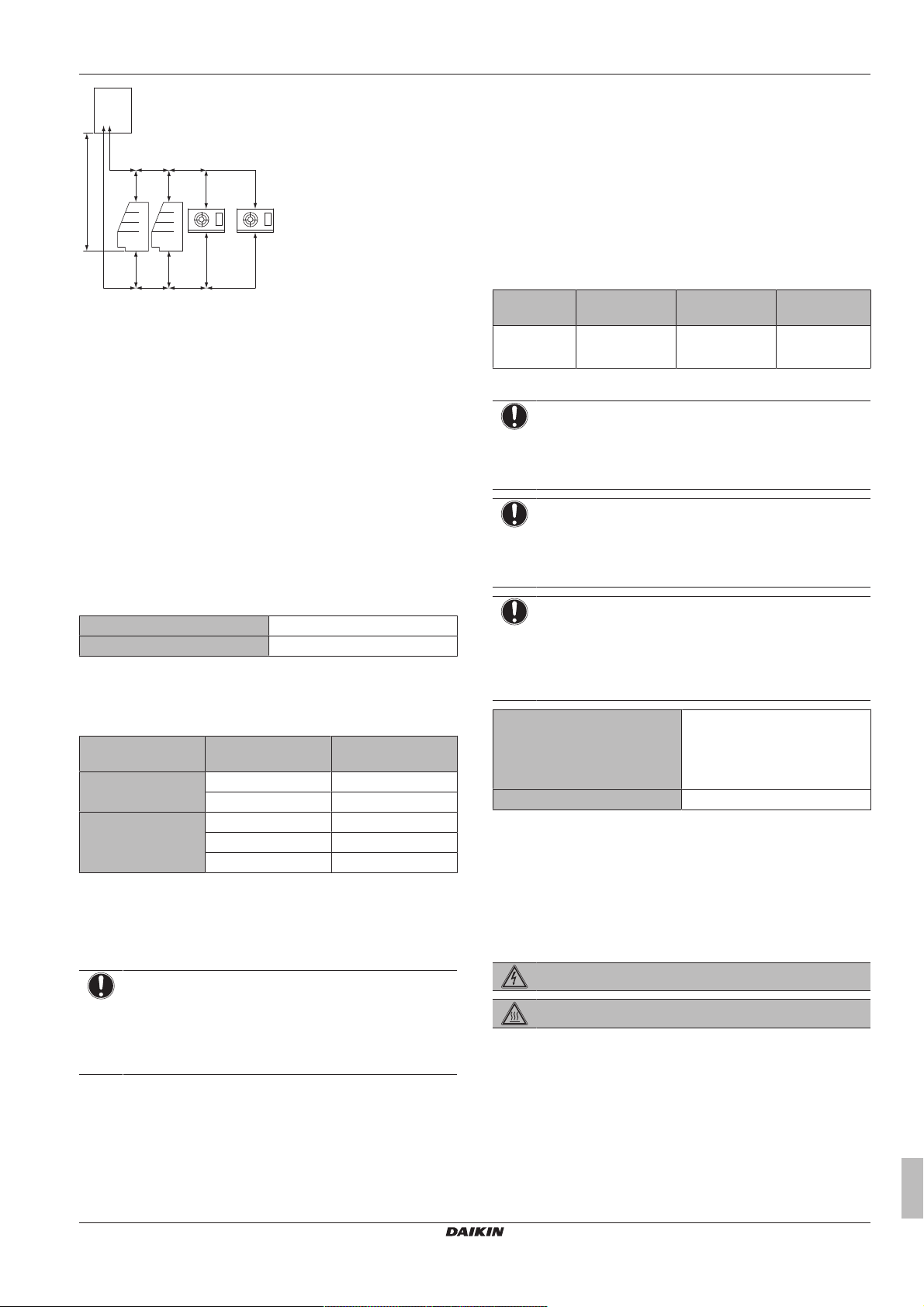
2.1.1 To remove the accessories from the outdoor unit
1 Remove the service cover. See "5.1.1 To open the outdoor
unit"on page7.
2 Remove the accessories.
▪ Installer and user reference guide:
▪ Preparation of the installation, technical specifications,
reference data,…
▪ Detailed step-by-step instructions and background information
for basic and advanced usage
▪ Format: Digital files on http://www.daikineurope.com/support-
and-manuals/product-information/
Latest revisions of the supplied documentation may be available on
the regional Daikin website or via your dealer.
The original documentation is written in English. All other languages
are translations.
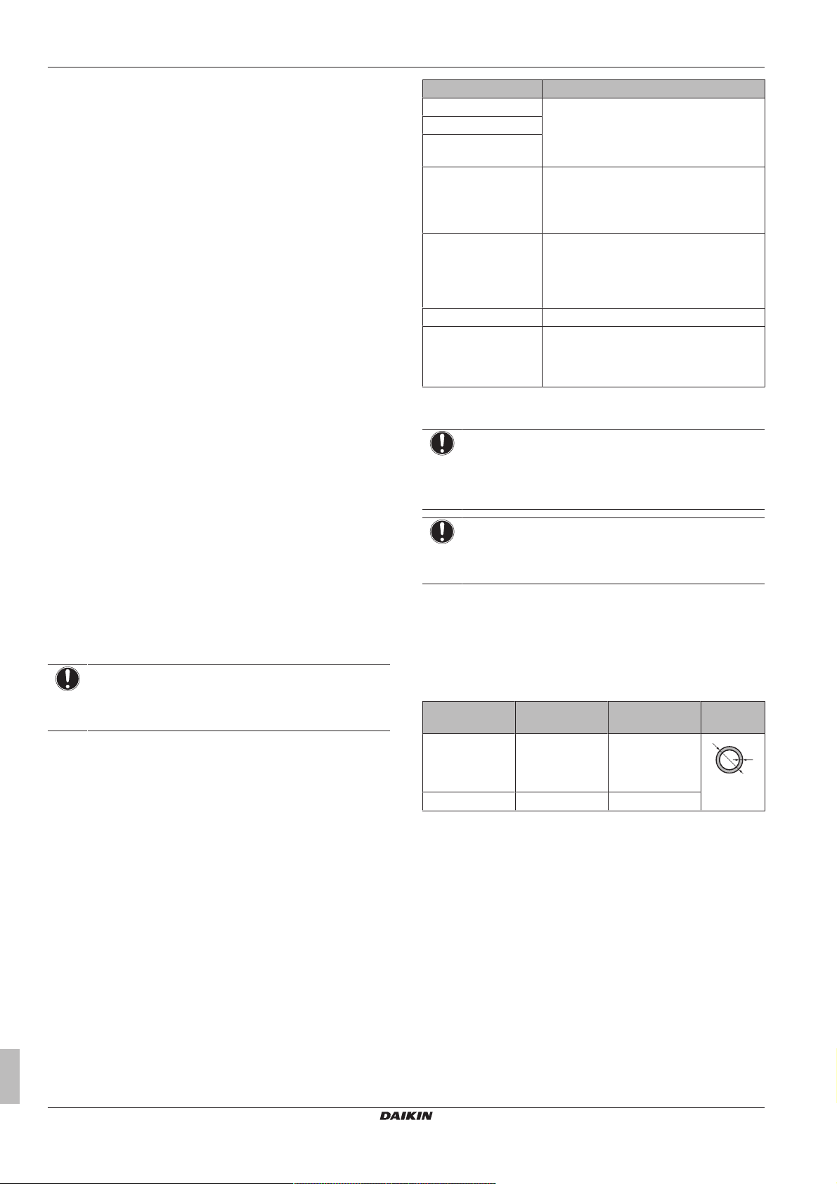
3.2 System layout
a Outdoor unit (ZEAS condensing unit)
b Refrigerant piping
c Indoor unit (Blower coil)
d Indoor unit (Showcase)
a General safety precautions
b Outdoor unit installation and operation manual
c Fluorinated greenhouse gases label
d Multilingual fluorinated greenhouse gases label
3 About the units
3.1 About the outdoor unit
This installation manual concerns the ZEAS condensing unit.
This unit is intended for outdoor installation and aimed for air to air
cooling applications.
Specification LRMEQ3+4
Capacity (cooling) 5.90~8.40kW
Ambient design temperature (cooling) –10~43°CDB
3.3 About the indoor units
NOTICE
To be sure your system setup (outdoor unit+indoor unit(s))
will work, you have to consult the latest technical
engineering data for ZEAS condensing unit.
The ZEAS condensing unit can be combined with several types of
third party indoor units and is intended for R410A use only.
When installing indoor units, mind the following:
▪ Expansion valve. Install an R410A mechanical thermostatic
expansion valve on each indoor unit. Insulate the feeler block of
the mechanical thermostatic expansion valve.
▪ Solenoid valve. Install an R410A solenoid valve (with an
operating differential pressure of 3.5MPa [35bar] or more) on the
primary side of the mechanical thermostatic expansion valve for
each indoor unit.
▪ Filter. Install a filter on the primary side of the solenoid valve for
each indoor unit. Determine the filter mesh count based on the
size specified by the solenoid valve and the mechanical
thermostatic expansion valve being used.
▪ Refrigerant flow. Route the path to the indoor unit heat
exchanger so that the refrigerant flow is from top to bottom.
▪ Multiple indoor units. When installing multiple indoor units,
install them at the same level. A combination of showcases and
blower coils is allowed if they are installed on the same floor.
▪ Defrosting type. Use either off-cycle defrosting or electric heater
defrosting models. Do NOT use hot-gas defrosting models.
LRMEQ3+4AY1
Air-cooled refrigeration condensing unit
4P441336-1 – 2016.03
Installation and operation manual
5
Page 6
4 Preparation
t
Ø
3.3.1 About reusing existing indoor heat exchangers
In some cases you may reuse existing indoor heat exchangers, in
other cases not.
Reuse not allowed
You may not reuse existing indoor heat exchangers in the following
cases:
▪ When the design pressure is insufficient. (minimum design
pressure = 2.5MPa [25bar])
▪ When the path to the heat exchanger has been routed so that the
flow of refrigerant is from bottom to top.
▪ When the copper piping or fan is corroded.
▪ When the heat exchanger is contaminated. Foreign materials
(including oils for fabrication) must be ≤30mg/10m.
Reuse allowed
In other cases than above, you may reuse existing indoor heat
exchangers. However, if the old condensing unit did NOT use the
same refrigerant (R410A) and the same oil (FVC68D) as the new
one, you must clean the heat exchanger tubes to remove any
residue.
If the old condensing unit did NOT use the same refrigerant (R410A)
as the new one, make sure the mechanical thermostatic expansion
valve is compatible with R410A.
4 Preparation
4.1 Preparing installation site
4.1.1 Installation site requirements of the outdoor unit
Mind the spacing guidelines. See the "Technical data" chapter, and
the figures on the inside of the front cover.
NOTICE
This is a class A product. In a domestic environment this
product may cause radio interference in which case the
user may be required to take adequate measures.
4.2 Preparing refrigerant piping
4.2.1 About reusing existing piping
In some cases you may reuse existing piping, in other cases not.
Reuse not allowed
You may not reuse existing piping in the following cases:
▪ When the compressor in the old installation had problems
(example: breakdown). Possible consequence: oxidised coolant
oil, scale residue and other adverse effects.
▪ When the indoor and outdoor units were disconnected from the
piping for a long time. Possible consequence: water and dirt in
the piping.
▪ When the copper piping is corroded.
Reuse allowed
In other cases than above, you may reuse existing piping but keep
the following in mind:
Item Description
Piping diameter Must comply with requirements. See
Piping material
Piping length and
height difference
Piping insulation If deteriorated, must be replaced.
Flare connections May not be reused. Make new ones to
Welded connections Must be checked for gas leaks.
Cleaning piping If the old condensing unit did NOT use the
"4.2.2Refrigerant piping requirements"on
page6.
Must comply with requirements. See
"5.5To insulate the refrigerant piping"on
page12.
prevent leaks. See "5.3.1Guidelines when
connecting the refrigerant piping"on
page8 and "5.3.2To flare the pipe
end"on page9.
same refrigerant (R410A) and the same oil
(FVC68D) as the new one, you must clean
the piping to remove any residue.
4.2.2 Refrigerant piping requirements
NOTICE
Refrigerant R410A requires strict cautions for keeping the
system clean and dry. Foreign materials (including mineral
oils or moisture) should be prevented from getting mixed
into the system.
NOTICE
The piping and other pressure-containing parts shall be
suitable for refrigerant. Use phosphoric acid deoxidised
seamless copper for refrigerant.
▪ Foreign materials inside pipes (including oils for fabrication) must
be ≤30 mg/10 m.
4.2.3 Refrigerant piping material
▪ Piping material: Phosphoric acid deoxidised seamless copper.
▪ Piping temper grade and thickness:
Outer diameter
(Ø)
6.4mm (1/4")
9.5mm (3/8")
12.7mm (1/2")
15.9mm (5/8") Annealed (O) ≥0.99mm
(a) Depending on the applicable legislation and the unit's
▪ Flare connections: Only use annealed material.
Temper grade Thickness (t)
Annealed (O) ≥0.80mm
maximum working pressure (see "PS High" on the unit
name plate), larger piping thickness might be required.
(a)
4.2.4 To select the piping size
Determine the proper size referring to following tables and reference
figure (only for indication).
Installation and operation manual
6
Air-cooled refrigeration condensing unit
LRMEQ3+4AY1
4P441336-1 – 2016.03
Page 7
F
A
1
2 3 3
d1
e
B
d2
C
c
D1
E
f
D2
ba
H
2
1 Outdoor unit
2 Indoor unit (Showcase)
3 Indoor unit (Blower coil)
A~F Liquid piping
a~f Gas piping
H Height difference outdoor-indoor
In case the required pipe sizes (inch sizes) are not available, it is
also allowed to use other diameters (mm sizes), taken the following
into account:
▪ Select the pipe size nearest to the required size.
▪ Use the suitable adapters for the change-over from inch to mm
pipes (field supply).
▪ The additional refrigerant calculation has to be adjusted as
mentioned in "5.6.2 To determine the additional refrigerant
amount"on page12.
A/a: Piping between outdoor unit and piping branching
Use the same diameters as the connections on the outdoor units:
Liquid piping Ø9.5 mm
Gas piping Ø15.9 mm
B+C/b+c: Piping between piping branching
Use diameters depending on the total capacity of the indoor units
connected downstream.
Capacity Piping outer
diameter
Liquid piping <4.0kW Ø6.4mm
4.0≤x<8.4kW Ø9.5mm
Gas piping <1.0kW Ø9.5mm
1.0≤x<6.0kW Ø12.7mm
6.0≤x<8.4kW Ø15.9mm
5 Installation
4.3 Preparing electrical wiring
4.3.1 Safety device requirements
Power supply
The power supply must be protected with the required safety
devices, i.e. a main switch, a slow blow fuse on each phase and an
earth leakage protector in accordance with the applicable legislation.
Selection and sizing of the wiring should be done in accordance with
the applicable legislation based on the information mentioned in the
table below.
Model Minimum circuit
ampacity
LRMEQ3+4 13.5A 16A 3N~ 50Hz
Operation switch, low-noise switch and error output wiring
NOTICE
Operation switch. An operation switch is required to turn
outdoor unit operation ON/OFF. The outdoor unit cannot
operate without it. Use a voltage-free contact for
microcurrent (≤1mA, 12VDC).
NOTICE
Low-noise switch. If you want to remotely turn ON/OFF
low-noise operation (see setting [2‑25]), you must install a
low-noise switch. Use a voltage-free contact for
microcurrent (≤1mA, 12VDC).
NOTICE
Error output. If system malfunctions are likely to degrade
the articles in the room/showcase, you can install an alarm
(example: lamp). If a malfunction occurs, a signal
(220-240VAC) is given to the error output (X2M/E1/E2).
Use an alarm with a maximum load of 0.5A.
Wiring Sheathed + shielded cable (2
Maximum wiring length 130m
Recommended
fuses
Vinyl cords
0.75~1.25mm²
Power supply
380-415V
wires)
5 Installation
D~F/d~f: Piping between piping branching and indoor unit
Use the same diameters as the connections (liquid, gas) on the
indoor units.
NOTICE
If only 1 indoor unit is connected to the outdoor unit, and
the connections on the outdoor unit are different from
those on the indoor unit, then use the same piping
diameter as the connections on the outdoor unit, and install
suitable adapters as near to the indoor unit as possible.
LRMEQ3+4AY1
Air-cooled refrigeration condensing unit
4P441336-1 – 2016.03
5.1 Opening the units
5.1.1 To open the outdoor unit
DANGER: RISK OF ELECTROCUTION
DANGER: RISK OF BURNING
Installation and operation manual
7
Page 8
5 Installation
1×
1
2
(mm)
>150
620
350
(345-355)
4× M12
a
20
a
4× M12
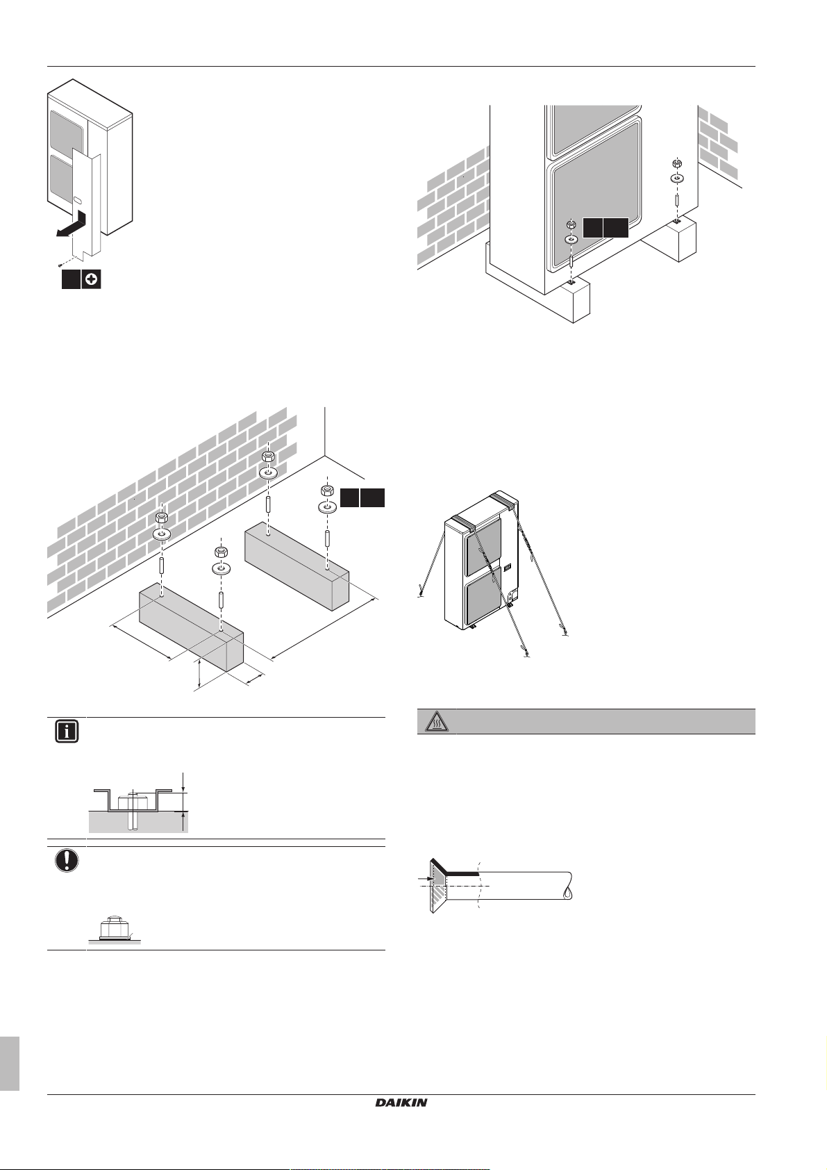
5.2 Mounting the outdoor unit
5.2.2 To install the outdoor unit
5.2.1 To provide the installation structure
Prepare 4 sets of anchor bolts, nuts and washers (field supply) as
follows:
a Make sure not to cover the drain holes.
INFORMATION
The recommended height of the upper protruding part of
the bolts is 20mm.
NOTICE
Fix the outdoor unit to the foundation bolts using nuts with
resin washers (a). If the coating on the fastening area is
stripped off, the nuts rust easily.
5.2.3 To prevent the outdoor unit from falling over
1 Prepare 2 cables as indicated in the following illustration (field
supply).
2 Place the 2 cables over the outdoor unit.
3 Insert a rubber sheet between the cables and the outdoor unit
to prevent the cable from scratching the paint (field supply).
4 Attach the cable’s ends. Tighten those ends.
5.3 Connecting the refrigerant piping
DANGER: RISK OF BURNING
5.3.1 Guidelines when connecting the refrigerant piping
Take the following guidelines into account when connecting pipes:
▪ Coat the flare inner surface with ether oil or ester oil when
connecting a flare nut. Tighten 3 or 4 turns by hand, before
tightening firmly.
Installation and operation manual
8
▪ Always use two wrenches together when loosening a flare nut.
▪ Always use a spanner and torque wrench together to tighten the
flare nut when connecting the piping. This to prevent nut cracking
and leaks.
LRMEQ3+4AY1
Air-cooled refrigeration condensing unit
4P441336-1 – 2016.03
Page 9
a b
c
d
a Torque wrench
R=0.4~0.8
45°
±2
90°
±2
A
a b
A
a b
c
1
2
3
4
a bb c
b Spanner
c Piping union
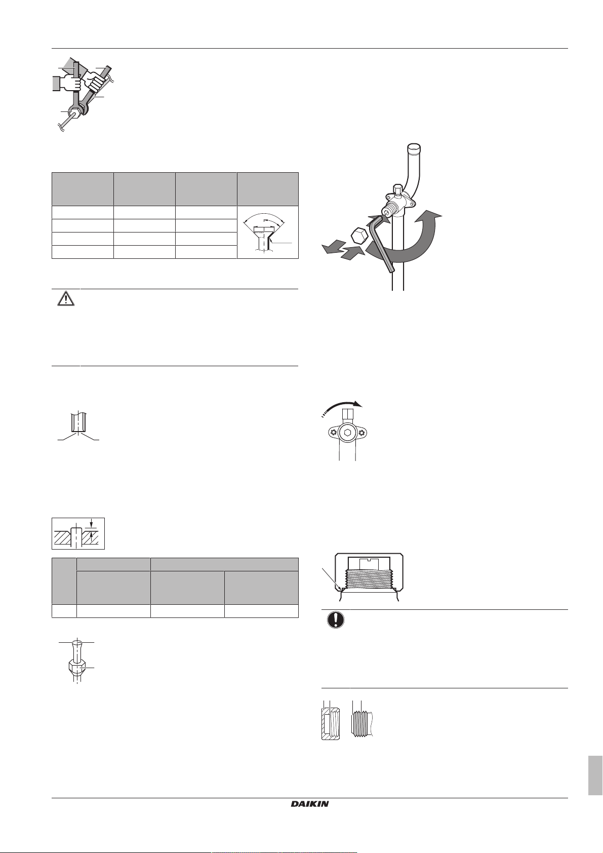
d Flare nut
Piping size
(mm)
Tightening
torque (N•m)
Flare
dimensions (A)
Flare shape
(mm)
(mm)
Ø6.4 15~17 8.7~9.1
Ø9.5 33~39 12.8~13.2
Ø12.7 50~60 16.2~16.6
Ø15.9 63~75 19.3~19.7
5.3.2 To flare the pipe end
CAUTION
▪ Incomplete flaring may cause refrigerant gas leakage.
▪ Do NOT re-use flares. Use new flares to prevent
refrigerant gas leakage.
▪ Use flare nuts that are included with the unit. Using
different flare nuts may cause refrigerant gas leakage.
1 Cut the pipe end with a pipe cutter.
2 Remove burrs with the cut surface facing downward so that the
chips do not enter the pipe.
5 Installation
To open the stop valve
1 Remove the stop valve cover.
2 Insert a hexagon wrench into the stop valve and turn the stop
valve counterclockwise.
3 When the stop valve cannot be turned any further, stop turning.
Result: The valve is now open.
To close the stop valve
1 Remove the stop valve cover.
2 Insert a hexagon wrench into the stop valve and turn the stop
valve clockwise.
3 When the stop valve cannot be turned any further, stop turning.
Result: The valve is now closed.
Closing direction:
a Cut exactly at right angles.
b Remove burrs.
3 Remove the flare nut from the stop valve and put the flare nut
on the pipe.
4 Flare the pipe. Set exactly at the position as shown in the
following illustration.
Conventional flare tool
Flare tool for
R410A (clutch
type)
Clutch type
(Ridgid-type)
Wing nut type
(Imperial-type)
A 0~0.5mm 1.0~1.5mm 1.5~2.0mm
5 Check that the flaring is properly made.
a Flare’s inner surface must be flawless.
b The pipe end must be evenly flared in a perfect circle.
c Make sure the flare nut is fitted.
5.3.3 Using the stop valve and service port
To handle the stop valve cover
▪ The stop valve cover is sealed where indicated by the arrow. Take
care not to damage it.
▪ After handling the stop valve, make sure to tighten the stop valve
cover securely. For the tightening torque, refer to the table below.
▪ Check for refrigerant leaks after tightening the stop valve cover.
NOTICE
Thread-locking fluid. Before reattaching the stop valve
cover, apply thread-locking fluid to the screw thread (NOT
to the cover or sealing part). Otherwise, condensation
water might enter and freeze. Possible consequence:
Deformation, refrigerant leakage and compressor
malfunction.
To handle the stop valve
▪ Make sure to keep all stop valves open during operation.
▪ The stop valve is factory closed.
LRMEQ3+4AY1
Air-cooled refrigeration condensing unit
4P441336-1 – 2016.03
a Cover (do NOT apply thread-locking fluid)
b Sealing part (do NOT apply thread-locking fluid)
c Screw thread with thread-locking fluid
Installation and operation manual
9
Page 10

5 Installation
c
b
a
a b
a b
c
a
b
d
a
b
c
d
cc
ba
4× Ø6 mm
To handle the service port
▪ Always use a charge hose equipped with a valve depressor pin,
since the service port is a Schrader type valve.
▪ After handling the service port, make sure to tighten the service
port cover securely. For the tightening torque, refer to the table
below.
▪ Check for refrigerant leaks after tightening the service port cover.
NOTICE
Thread-locking fluid. Before reattaching the service port
cover, apply thread-locking fluid to the screw thread (NOT
to the cover or sealing part) . Otherwise, condensation
water might enter and freeze. Possible consequence:
Deformation, refrigerant leakage and compressor
malfunction.
a Cover (do NOT apply thread-locking fluid)
b Sealing part (do NOT apply thread-locking fluid)
c Screw thread with thread-locking fluid
Tightening torques
Stop valve
size (mm)
Ø9.5 5.4~6.6 4mm 13.5~16.5 11.5~13.9
Ø15.9 13.5~16.5 6mm 22.5~27.5
Tightening torque N•m (turn clockwise to close)
Shaft
Valve body Hexagonal
wrench
Cap (valve
lid)
Service
port
5.3.4 Guidelines when installing a sight glass
Install a sight glass on the liquid piping:
Where/how Install the dryer after the sight glass, as near to
the outdoor unit as possible. Install
horizontally.
a Sight glass
b Dryer
When brazing Follow the brazing instructions in the dryer
manual.
Remove the dryer cap immediately before
brazing (to prevent absorption of airborne
moisture).
If dryer paint burnt during brazing, repair it. For
repair paint details, contact the manufacturer.
Flow direction If the dryer specifies a flow direction, install
accordingly.
5.3.6 To connect the refrigerant piping to the outdoor unit
NOTICE
Be sure that the field installed piping does not touch other
pipes, the bottom panel or side panel. Especially for the
bottom and side connection, be sure to protect the piping
with suitable insulation, to prevent it from coming into
contact with the casing.
1 Do the following:
▪ Remove the service cover (a) with screw (b).
▪ Remove the piping intake plate (c) with screw (d).
Diameter 9.5mm
Where/how Install the sight glass before the dryer, as near
to the outdoor unit as possible. Install
horizontally.
a Sight glass
b Dryer
When brazing Follow the brazing instructions in the sight
glass manual.
5.3.5 Guidelines when installing a dryer
NOTICE
Do NOT operate the unit without a dryer installed.
Possible consequence: Equipment malfunction.
Install a dryer on the liquid piping:
Dryer type 80g (100% molecular sieve equivalent)
(DML083/DML083S: Danfoss made)
2 Choose a piping route (a, b, c or d).
3 If you have chosen the downwards piping route:
▪ Drill (a, 4×) and remove the knockout hole (b).
▪ Cut out the slits (c) with a metal saw.
Installation and operation manual
10
4 Do the following:
LRMEQ3+4AY1
Air-cooled refrigeration condensing unit
4P441336-1 – 2016.03
Page 11

5 Installation
a
b
a
p<p
>
N2
C
b c e
a
g
f
d
A B
▪ Connect the liquid pipe (a) to the liquid stop valve.
▪ Connect the gas pipe (b) to the gas stop valve.
5 Reattach the service cover and the piping intake plate.
6 Seal all gaps (example: a) to prevent snow and small animals
from entering the system.
WARNING
Provide adequate measures to prevent that the unit can be
used as a shelter by small animals. Small animals that
make contact with electrical parts can cause malfunctions,
smoke or fire.
NOTICE
Make sure to open the stop valves after installing the
refrigerant piping and performing vacuum drying. Running
the system with the stop valves closed may break the
compressor.
5.4 Checking the refrigerant piping
5.4.1 About checking the refrigerant piping
Checking the refrigerant piping involves:
▪ Checking for any leakages in the refrigerant piping.
▪ Performing vacuum drying to remove all moisture, air or nitrogen
in the refrigerant piping.
If there is a possibility of moisture being present in the refrigerant
piping (for example, water may have entered the piping), first carry
out the vacuum drying procedure below until all moisture has been
removed.
All piping inside the unit has been factory tested for leaks.
Only field installed refrigerant piping needs to be checked.
Therefore, make sure that all the outdoor unit stop valves are firmly
closed before performing leak test or vacuum drying.
NOTICE
Make sure that all (field supplied) field piping valves are
OPEN (not outdoor unit stop valves!) before you start leak
test and vacuuming.
For more information on the state of the valves, refer to
"5.4.3Checking refrigerant piping: Setup"on page11.
5.4.2 Checking refrigerant piping: General guidelines
Connect the vacuum pump through a manifold to the service port of
all stop valves to increase efficiency (refer to "5.4.3 Checking
refrigerant piping: Setup"on page11).
NOTICE
Use a 2-stage vacuum pump with a non-return valve or a
solenoid valve that can evacuate to a gauge pressure of
–100.7kPa (5Torr absolute).
LRMEQ3+4AY1
Air-cooled refrigeration condensing unit
4P441336-1 – 2016.03
NOTICE
Make sure the pump oil does not flow oppositely into the
system while the pump is not working.
NOTICE
Do not purge the air with refrigerants. Use a vacuum pump
to evacuate the installation.
5.4.3 Checking refrigerant piping: Setup
a Pressure reducing valve
b Nitrogen
c Weighing scales
d Refrigerant R410A tank (siphon system)
e Vacuum pump
f Liquid line stop valve
g Gas line stop valve
A Valve A
B Valve B
C Valve C
Valve State of valve
Valve A Open
Valve B Open
Valve C Open
Liquid line stop valve Close
Gas line stop valve Close
NOTICE
Indoor units should also be leak and vacuum tested. Keep
any possible (field supplied) field piping valves open as
well.
5.4.4 To perform a leak test
The leak test must satisfy the specifications of EN378‑2.
To check for leaks: Vacuum leak test
1 Evacuate the system from the liquid and gas piping to
–100.7kPa (–1.007bar/5Torr) for more than 2 hours.
2 Once reached, turn off the vacuum pump and check that the
pressure does not rise for at least 1 minute.
3 Should the pressure rise, the system may either contain
moisture (see vacuum drying below) or have leaks.
To check for leaks: Pressure leak test
1 Break the vacuum by pressurising with nitrogen gas to a
minimum gauge pressure of 0.2MPa (2bar).
▪ Never set the gauge pressure of the high pressure section
of the system higher than the maximum operation pressure
of 4.0MPa (40bar).
▪ Never set the gauge pressure of the low pressure section
of the system higher than the design pressure of the indoor
unit.
2 Test for leaks by applying a bubble test solution to all piping
connections.
3 Discharge all nitrogen gas.
Installation and operation manual
11
Page 12

5 Installation
b
a
NOTICE
Make sure to use a recommended bubble test solution
from your wholesaler. Do not use soap water, which may
cause cracking of flare nuts (soap water may contain salt,
which absorbs moisture that will freeze when the piping
gets cold), and/or lead to corrosion of flared joints (soap
water may contain ammonia which causes a corrosive
effect between the brass flare nut and the copper flare).
5.4.5 To perform vacuum drying
To remove all moisture from the system, proceed as follows:
1 Evacuate the system for at least 2 hours to a target vacuum of
–100.7kPa (–1.007bar/5Torr).
2 Check that, with the vacuum pump turned off, the target
vacuum is maintained for at least 1 hour.
3 Should you fail to reach the target vacuum within 2 hours or
maintain the vacuum for 1 hour, the system may contain too
much moisture. In that case, break the vacuum by pressurising
with nitrogen gas to a gauge pressure of 0.05 MPa (0.5 bar)
and repeat steps 1 to 3 until all moisture has been removed.
4 Depending on whether you want to immediately charge
refrigerant through the refrigerant charge port or first pre-charge
a portion of refrigerant through the liquid line, either open the
outdoor unit stop valves, or keep them closed. See "5.6.3To
charge refrigerant"on page13 for more information.
5.5 To insulate the refrigerant piping
After finishing the leak test and vacuum drying, the piping must be
insulated. Take into account the following points:
▪ Make sure to insulate the connection piping and refrigerant piping
branching entirely.
▪ Be sure to insulate the liquid and gas piping (for all units).
▪ Use heat resistant polyethylene foam which can withstand a
temperature of 70°C for liquid piping and polyethylene foam which
can withstand a temperature of 120°C for gas piping.
▪ Take the following into account when determining the insulation
thickness:
Liquid pipe minimum temperature 20°C
Gas pipe minimum temperature –10°C
Condensation might form on the surface of the insulation.
▪ If there is a possibility that condensation on the stop valve might
drip down into the indoor unit through gaps in the insulation and
piping because the outdoor unit is located higher than the indoor
unit, this must be prevented by sealing up the connections. See
below figure.
a Insulation material
b Caulking etc.
5.6 Charging refrigerant
5.6.1 Precautions when charging refrigerant
WARNING
▪ Only use R410A as refrigerant. Other substances may
cause explosions and accidents.
▪ R410A contains fluorinated greenhouse gases. Its
global warming potential (GWP) value is 2087.5. Do
NOT vent these gases into the atmosphere.
▪ When charging refrigerant, always use protective
gloves and safety glasses.
NOTICE
If the power of some units is turned off, the charging
procedure cannot be finished properly.
NOTICE
Be sure to turn on the power 6 hours before operation in
order to have power running to the crankcase heater and
to protect the compressor.
NOTICE
Before starting charging procedures, check if the 7‑LEDs
display is as normal (see "6.1.4To access mode 1 or 2"on
page 17). If a malfunction code is present, see
"8.1Solving problems based on error codes"on page21.
NOTICE
Close the front panel before any refrigerant charge
operation is executed. Without the front panel attached the
unit cannot judge correctly whether it is operating properly
or not.
NOTICE
In case of maintenance and the system (outdoor unit+field
piping+indoor units) does not contain any refrigerant any
more (e.g., after refrigerant reclaim operation), the unit has
to be charged with its original amount of refrigerant (refer
to the nameplate on the unit) and the determined additional
refrigerant amount.
5.6.2 To determine the additional refrigerant amount
INFORMATION
For final charge adjustment in a test laboratory, contact
your dealer.
Additional refrigerant to be charged=R (kg). R should be rounded off
in units of 0.1kg.
R=[(X1×Ø9.5)×0.059+(X2×Ø6.4)×0.022]+A1+A2
X
=Total length (m) of liquid piping size at Øa
1...2
Parameter A1:
If the total capacity
(a) Capacity at evaporating temperature of –10°C
Parameter A2:
If the total capacity
(a)
of showcases is... Then A1 is...
<5.0kW 1.1kg
5.0≤x<8.4kW 2.3kg
(a)
of blower coils is... Then A2 is...
<5.0kW 0.6kg
5.0≤x<8.4kW 1.2kg
Installation and operation manual
12
Air-cooled refrigeration condensing unit
LRMEQ3+4AY1
4P441336-1 – 2016.03
Page 13

5 Installation
p<p
>
N2
C
b c e
a
g
f
d
A B
b
a
c d
p<p
>
a c
d
b
A
d
(a) Capacity at temperature difference (=evaporating
temperature – room temperature) of 10°C
Metric piping. When using metric piping, please take into account
following table concerning the weight factor to be allocated. It should
be substituted in the formula for R.
Inch piping Metric piping
Size (Ø) (mm) Weight factor Size (Ø) (mm) Weight factor
6.4 0.022 6 0.018
9.5 0.059 10 0.065
5.6.3 To charge refrigerant
To speed up the refrigerant charging process, it is recommended to
first pre-charge a portion of refrigerant through the liquid line before
proceeding with the charging via the refrigerant charging port. It can
be skipped, but charging will take longer then.
Pre-charging refrigerant
Pre-charging can be done without compressor operation, by
connecting the refrigerant bottle to the service port of the liquid stop
valve.
1 Connect as shown. Make sure that all outdoor unit stop valves,
as well as valve A are closed.
5 Open all outdoor unit stop valves.
6 Take all the precautions mentioned in "6 Configuration" on
page16 and "7Commissioning"on page19 into account.
7 Turn on the power of the outdoor unit, but leave the external
operation switch turned off (see "5.7.4To connect the electrical
wiring on the outdoor unit"on page15).
8 Set the target evaporating temperature with setting [2‑8] (see
"6.1.8Mode 2: Field settings"on page18).
9 Turn on the power of the indoor units.
10 Turn on the external operation switch.
Result: The unit will start operation.
INFORMATION
▪ When a malfunction is detected during the procedure
(e.g., in case of closed stop valve), a malfunction code
will be displayed. In that case, refer to "5.6.4 Error
codes when charging refrigerant" on page 14 and
solve the malfunction accordingly.
▪ Aborting the manual refrigerant charge is possible by
turning OFF the external operation switch. The unit will
stop and return to idle condition.
11 Check the sight glass of the outdoor unit. If the refrigerant is
NOT in sealing state, charge extra refrigerant as described in
the "Charging refrigerant (via the refrigerant charging
port)" instructions, but do NOT exceed 10% of the determined
additional refrigerant amount (see "5.6.2 To determine the
additional refrigerant amount"on page12).
a Pressure reducing valve
b Nitrogen
c Weighing scales
d Refrigerant R410A tank (siphon system)
e Vacuum pump
f Liquid line stop valve
g Gas line stop valve
A Valve A
B Valve B
C Valve C
2 Open valves C and B.
3 Pre‑charge refrigerant until the determined additional refrigerant
amount is reached or pre‑charging is not possible anymore, and
then close valves C and B.
4 Do one of the following:
If Then
The determined additional
refrigerant amount is reached
Disconnect the manifold from
the liquid line.
Continue with the "Checking
the sight glass" instructions.
Too much refrigerant is
charged
Recover refrigerant.
Disconnect the manifold from
the liquid line.
Continue with the "Checking
the sight glass" instructions.
The determined additional
refrigerant amount is not
reached yet
Disconnect the manifold from
the liquid line.
Continue with the "Charging
refrigerant (via the
refrigerant charging port)"
instructions.
Checking the sight glass
If the determined additional refrigerant amount is reached by the
"Pre-charging refrigerant" instructions, continue as follows:
LRMEQ3+4AY1
Air-cooled refrigeration condensing unit
4P441336-1 – 2016.03
O Sealing state (= sufficient refrigerant)
X Insufficient refrigerant
a Sight glass
b Full of liquid
c A little foam in the liquid
d A lot of foam in the liquid
12 Turn off the external operation switch.
Charging refrigerant (via the refrigerant charging port)
The remaining additional refrigerant charge can be charged by
operating the outdoor unit.
13 Connect as shown. Make sure valve A is closed.
a Weighing scales
b Refrigerant R410A tank (siphon system)
c Vacuum pump
d Refrigerant charge port
A Valve A
NOTICE
The refrigerant charging port is connected to the piping
inside the unit. The unit's internal piping is already factory
charged with refrigerant, so be careful when connecting
the charge hose.
14 Open all outdoor unit stop valves. At this point, valve A must
remain closed!
Installation and operation manual
13
Page 14

5 Installation
b
a
c d
c
b
a
b
Contains fluorinated greenhouse gases
2
1
1
1
2
2
kg
tCO2eq
GWP × kg
1000
=
=
+
kg
=
kg
=
GWP: XXX
RXXX
a
f
c
d
e
15 Take all the precautions mentioned in "6 Configuration" on
page16 and "7Commissioning"on page19 into account.
16 Turn on the power of the outdoor unit, but leave the external
operation switch turned off (see "5.7.4To connect the electrical
wiring on the outdoor unit"on page15).
17 Set the target evaporating temperature with setting [2‑8] (see
"6.1.8Mode 2: Field settings"on page18).
18 Turn on the power of the indoor units.
19 Turn on the external operation switch.
Result: The unit will start operation.
INFORMATION
▪ When a malfunction is detected during the procedure
(e.g., in case of closed stop valve), a malfunction code
will be displayed. In that case, refer to "5.6.4 Error
codes when charging refrigerant" on page 14 and
solve the malfunction accordingly.
▪ Aborting the manual refrigerant charge is possible by
turning OFF the external operation switch. The unit will
stop and return to idle condition.
20 Open valve A.
21 Charge refrigerant until the remaining determined additional
refrigerant amount is added (see "5.6.2 To determine the
additional refrigerant amount" on page 12), and then close
valve A.
22 Check the sight glass of the outdoor unit. If the refrigerant is
NOT in sealing state, charge extra refrigerant, but do NOT
exceed 10% of the determined additional refrigerant amount
(see "5.6.2To determine the additional refrigerant amount" on
page12).
O Sealing state (= sufficient refrigerant)
X Insufficient refrigerant
a Sight glass
b Full of liquid
c A little foam in the liquid
d A lot of foam in the liquid
23 Turn off the external operation switch.
NOTICE
Make sure to open all stop valves after (pre-) charging the
refrigerant.
Operating with the stop valves closed will damage the
compressor.
a Cover (do NOT apply thread-locking fluid)
b Sealing part (do NOT apply thread-locking fluid)
c Screw thread with thread-locking fluid
5.6.4 Error codes when charging refrigerant
INFORMATION
If a malfunction occurs, a signal (220-240VAC) is given to
the error output (X2M/E1/E2), and the H2P LED on the
main PCB is lit.
If a malfunction occurs, close valve A immediately. Confirm the
malfunction code and take corresponding action, "8.1 Solving
problems based on error codes"on page21.
5.6.5 To fix the fluorinated greenhouse gases label
1 Fill in the label as follows:
a If a multilingual fluorinated greenhouse gases label is
delivered with the unit (see accessories), peel off the
applicable language and stick it on top of a.
b Factory refrigerant charge: see unit name plate
c Additional refrigerant amount charged
d Total refrigerant charge
e Greenhouse gas emissions of the total refrigerant charge
expressed as tonnes CO2-equivalent
f GWP = Global warming potential
NOTICE
In Europe, the greenhouse gas emissions of the total
refrigerant charge in the system (expressed as tonnes
CO2-equivalent) is used to determine the maintenance
intervals. Follow the applicable legislation.
Formula to calculate the greenhouse gas emissions:
GWP value of the refrigerant × Total refrigerant charge [in
kg] / 1000
2 Fix the label on the inside of the outdoor unit near the gas and
liquid stop valves.
NOTICE
5.7 Connecting the electrical wiring
After adding the refrigerant, do not forget to close the lid of
the refrigerant charging port. The tightening torque for the
lid is 11.5 to 13.9N•m.
5.7.1 Field wiring: Overview
Field wiring consists of the following:
NOTICE
Thread-locking fluid. Before reattaching the service port
cover, apply thread-locking fluid to the screw thread (NOT
to the cover or sealing part) . Otherwise, condensation
water might enter and freeze. Possible consequence:
Deformation, refrigerant leakage and compressor
malfunction.
Installation and operation manual
14
Air-cooled refrigeration condensing unit
LRMEQ3+4AY1
4P441336-1 – 2016.03
Page 15

3N~ 50 Hz
380-415 V
L1 L2 L3
L1 L2 L3
N
X1M
a
d e f
b
c
BA C E1 E2
X2M
a Earth leakage circuit breaker
b
c
a
BA C E1 E2
X2M
BA C E1 E2
X2M
BA C E1 E2
X2M
b Fuse
c Power supply (including earth) (sheathed cable)
d Low-noise switch
e Operation switch
f Error output
NOTICE
Operation switch. An operation switch is required to turn
outdoor unit operation ON/OFF. The outdoor unit cannot
operate without it. Use a voltage-free contact for
microcurrent (≤1mA, 12VDC).
NOTICE
Low-noise switch. If you want to remotely turn ON/OFF
low-noise operation (see setting [2‑25]), you must install a
low-noise switch. Use a voltage-free contact for
microcurrent (≤1mA, 12VDC).
5 Installation
5.7.3 Guidelines when connecting the electrical wiring
Tightening torques
Wiring Screw size Tightening
Power supply wiring
M5 2.2~2.7
(power supply + shielded
ground)
Operation switch, low-
M3.5 0.8~0.97
noise switch and error
output
5.7.4 To connect the electrical wiring on the outdoor unit
NOTICE
▪ Follow the wiring diagram (delivered with the unit,
located at the inside of the service cover).
▪ Make sure the electrical wiring does NOT obstruct
proper reattachment of the service cover.
1 Remove the service cover.
2 Connect the operation switch as follows:
torque (N•m)
NOTICE
Error output. If system malfunctions are likely to degrade
the articles in the room/showcase, you can install an alarm
(example: lamp). If a malfunction occurs, a signal
(220-240VAC) is given to the error output (X2M/E1/E2).
Use an alarm with a maximum load of 0.5A.
5.7.2 Guidelines when knocking out knockout holes
NOTICE
Precautions when making knockout holes:
▪ Avoid damaging the casing.
▪ After making the knockout holes, we recommend you
remove the burrs and paint the edges and areas
around the edges using repair paint to prevent rusting.
▪ When passing electrical wiring through the knockout
holes, wrap the wiring with protective tape to prevent
damage.
NOTICE
Operation switch. An operation switch is required to turn
outdoor unit operation ON/OFF. The outdoor unit cannot
operate without it. Use a voltage-free contact for
microcurrent (≤1mA, 12VDC).
3 Connect the low-noise switch as follows:
NOTICE
Low-noise switch. If you want to remotely turn ON/OFF
low-noise operation (see setting [2‑25]), you must install a
low-noise switch. Use a voltage-free contact for
microcurrent (≤1mA, 12VDC).
4 Connect the error output as follows:
a Knockout hole
b Burr
c Sealant etc.
LRMEQ3+4AY1
Air-cooled refrigeration condensing unit
4P441336-1 – 2016.03
NOTICE
Error output. If system malfunctions are likely to degrade
the articles in the room/showcase, you can install an alarm
(example: lamp). If a malfunction occurs, a signal
(220-240VAC) is given to the error output (X2M/E1/E2).
Use an alarm with a maximum load of 0.5A.
5 Connect the power supply as follows:
Installation and operation manual
15
Page 16

6 Configuration
3N~ 50 Hz
380-415 V
L1 L2 L3
L1 L2 L3
N
X1M
a
b
c
e
f
b
d
c
a
X2M
X1M
a
b
a
b
a
b
2
3
1
a b c d e
A B
a Earth leakage circuit breaker
b Fuse
c Power supply cable
6 Fix the cables with cable ties.
Connecting to the
frame
When cables are routed from the unit, a
protection sleeve for the conduits (PG
insertions) can be inserted at the knockout
hole.
When you do not use a wire conduit,
protect the wires with vinyl tubes to
prevent the edge of the knockout hole from
cutting the wires.
A Inside of the outdoor unit
B Outside of the outdoor unit
a Wire
b Bush
c Nut
d Frame
e Hose
8 Reattach the service cover.
9 Connect an earth leakage circuit breaker and fuse to the power
supply line.
a Power supply (including earth)
b Error output
c Low-noise switch
d Operation switch
e Attachment plate
f Cable tie
7 Route the wiring through the frame and connect it to it.
Routing through
the frame
a Power supply cable and error output
cable
b Operation switch cable and low-noise
switch cable
6 Configuration
INFORMATION
It is important that all information in this chapter is read
sequentially by the installer and that the system is
configured as applicable.
DANGER: RISK OF ELECTROCUTION
6.1 Making field settings
6.1.1 About making field settings
To configure the condensing unit, you must give input to the outdoor
unit's main PCB (A1P). This involves the following field setting
components:
▪ Push buttons to give input to the PCB
▪ A display to read feedback from the PCB
Field settings are defined by their mode, setting and value. Example:
[2‑8]=4.
Mode 1 and 2
Mode Description
Mode 1
(monitoring
settings)
Mode1 can be used to monitor the current
situation of the outdoor unit. Some field setting
contents can be monitored as well.
Installation and operation manual
16
Air-cooled refrigeration condensing unit
LRMEQ3+4AY1
4P441336-1 – 2016.03
Page 17

6 Configuration
BS2
SET
BS1
MODE
BS3
RETURN
BS4
TEST
BS5
RESET
H1P H2P H3P H4P H5P H6P H7P H8P
A1P
A2P
X1M
X2M
MULTIDEMANDL.N.O.P.SLAVEMASTERIND
TEST/
HWL
MODE
H1P
H2P H3P H4PH5P H6P H7P
- + + + + +
[
H1P
32 16 8 4 2 1]
+ + + + +0 0 8 0 0 0
H1P
H2P H3P H4P H5P H6P H7P
- + + + + +
[
H1P
32 16 8 4 2 1]
+ + + + +0 0 0 4 0 0
10~12 min
b
c
a
BS1 [5 s]
BS1
BS1
BS1
a
cb
Mode Description
Mode 2
(field settings)
Mode2 is used to change the field settings of
the system. Consulting the current field setting
value and changing the current field setting
value is possible.
In general, normal operation can be resumed
without special intervention after changing field
settings.
Some field settings are used for special
operation. In such a case, it is required to abort
the special operation before normal operation
can restart. It will be indicated in below
explanations.
6.1.2 To access the field setting components
See "5.1.1To open the outdoor unit"on page7.
6.1.3 Field setting components
NOTICE
The DIP switch (DS1 on A1P) is not used. Do NOT change
the factory setting.
The components to make field settings are as follows:
Description
Value 4
(in mode 2)
(H2P~H7P = binary 4)
6.1.4 To access mode 1 or 2
After the units are turned ON, the display goes to its default
situation. From there, you can access mode1 and mode2.
Initialisation: default situation
NOTICE
Be sure to turn on the power 6 hours before operation in
order to have power running to the crankcase heater and
to protect the compressor.
Turn on the power supply of the outdoor unit, and turn on the
external operation switch. After initialisation, the display indication
state will be as below (default situation when shipped from factory).
Push buttons
Use the push buttons to make the field settings. Operate the push
buttons with an insulated stick (such as a closed ball-point pen) to
avoid touching of live parts.
7‑LEDs display
The display gives feedback about the field settings, which are
defined as [Mode-Setting]=Value.
Example:
LRMEQ3+4AY1
Air-cooled refrigeration condensing unit
4P441336-1 – 2016.03
BS1~BS5 Push buttons
H1P~H7P 7‑LEDs display
H8P LED for indication during initialisation
BS1 MODE: For changing the set mode
BS2 SET: For field setting
BS3 RETURN: For field setting
BS4 Not used
BS5 Not used
H1P Shows the mode
H2P~H7P Shows the settings and values, represented in binary code
H8P NOT used for field settings, but used during initialisation
) OFF ( ) Flashing ( )
ON (
Description
Default situation
(H1P OFF)
Mode 1
(H1P flashing)
Mode 2
(H1P ON)
Setting 8
(in mode 2)
(H2P~H7P = binary 8)
a Power ON
b Default situation
c LED indication when there is a malfunction
If the default situation is not displayed after 10~12 minutes, check
the malfunction code. Solve the malfunction code accordingly.
Switching between modes
Use BS1 to switch between the default situation, mode 1 and
mode2.
a Default situation (H1P OFF)
b Mode 1 (H1P flashing)
c Mode 2 (H1P ON)
BS1 Press BS1.
BS1 [5 s] Press BS1 for at least 5s.
INFORMATION
If you get confused in the middle of the process, press BS1
to return to the default situation.
6.1.5 To use mode 1
In mode 1 (and in default situation) you can read out some
information.
Example: 7‑LEDs display – Default situation
You can read out the status of low noise operation as follows:
Installation and operation manual
17
Page 18

6 Configuration
BS1 [5 s]
BS2 [X×]
BS2 [X×]b
a
BS3 [1×]c
BS3 [1×]d
BS3 [1×]
BS1 [1×]
# Action Button/display
1 Make sure the LEDs are
showing the default situation.
(H1P OFF)
2 Check the status of LED
H6P.
Example: 7‑LEDs display – Mode1
See "8.1.1 To display the error codes of the latest malfunctions" on
page21.
H6P OFF: Unit is currently
not operating under low noise
restrictions.
H6P ON: Unit is currently
operating under low noise
restrictions.
6.1.6 To use mode 2
In mode 2 you can make field settings to configure the system.
Example: 7‑LEDs display – Mode 2
You can change the value of setting [2‑8] (=Te target evaporating
temperature) to 4 (=–4°C) as follows:
# Action Button/display
1 Start from the default
situation.
2 Select mode 2.
3 Select setting 8.
("X×" depends on the setting
that you want to select.)
4 Select value 4 (=–4°C).
a: Display the current value.
b: Change to 4. ("X×"
depends on the current
value, and the value that you
want to select.)
c: Enter the value in the
system.
d: Confirm. The system starts
operating according to the
setting.
5 Quit mode 2.
(= binary 8)
6.1.7 Mode 1 (and default situation): Monitoring settings
In mode 1 (and in default situation) you can read out some
information.
7‑LEDs display – Default situation (H1P OFF)
You can read out the following information:
Value / Description
H6P Shows the status of low noise operation.
OFF
Unit is currently not operating under low noise
restrictions.
ON
Unit is currently operating under low noise
restrictions.
Low noise operation reduces the sound generated by the
unit compared to nominal operating conditions.
Low noise operation can be set in mode2. There are two
methods to activate low noise operation of the outdoor unit
system.
▪ The first method is to enable an automatic low noise
operation during night time by field setting. The unit will
operate at the selected low noise level during the
selected time frames.
▪ The second method is to enable low noise operation
based on an external input. For this operation a low noise
switch needs to be installed (see "5.7.4 To connect the
electrical wiring on the outdoor unit"on page15).
7‑LEDs display – Mode1 (H1P flashing)
You can read out the following information:
(
Setting
[1‑14]
Shows the latest malfunction
code.
[1‑15]
Shows the 2nd last malfunction
code.
[1‑16]
Shows the 3rd last malfunction
code.
)
Value / Description
For more information, see
"8.1Solving problems based on
error codes"on page21.
6.1.8 Mode 2: Field settings
In mode 2 you can make field settings to configure the system. The LEDs give a binary representation of the setting/value number.
Setting
[2‑8]
Te target evaporating temperature.
Installation and operation manual
18
(= binary)
(default)
Value
Description
–10°C
–8°C
–6°C
–4°C
–2°C
0°C
2°C
Air-cooled refrigeration condensing unit
4P441336-1 – 2016.03
LRMEQ3+4AY1
Page 19

7 Commissioning
Setting
(= binary)
[2‑18]
Fan high static pressure setting.
In order to increase the static pressure the outdoor unit fan is
delivering, this setting should be activated. For details about this
setting, see technical specifications.
[2‑21]
Refrigerant recovery/vacuuming mode.
In order to achieve a free pathway to reclaim refrigerant out of the
system or to remove residual substances or to vacuum the system
it is necessary to apply a setting which will open required valves in
the refrigerant circuit so the reclaim of refrigerant or vacuuming
process can be done properly.
[2‑22]
Automatic low noise setting and level during night time.
By changing this setting, you activate the automatic low noise
operation function of the unit and define the level of operation.
Depending on the chosen level, the noise level will be lowered.
The start and stop moments for this function are defined under
setting [2‑26] and [2‑27].
[2‑25]
Low noise operation level via the low noise switch.
If the system needs to be running under low noise operation
conditions when an external signal is sent to the unit, this setting
defines the level of low noise that will be applied.
[2‑26]
Low noise operation start time.
This setting is used in conjunction with setting [2‑22].
[2‑27]
Low noise operation stop time.
This setting is used in conjunction with setting [2‑22].
Value
Description
Deactivated.
(default)
Activated.
Deactivated.
(default)
Activated.
To stop the refrigerant recovery/vacuuming
mode, push BS1. If BS1 is not pushed, the
system will remain in refrigerant recovery/
vacuuming mode.
Deactivated
(default)
Level 1 Level 3<Level 2<Level 1
Level 2
Level 3
Level 1 Level 3<Level 2<Level 1
Level 2
(default)
Level 3
20h00
22h00
(default)
24h00
6h00
7h00
8h00
(default)
7 Commissioning
After installation and once the field settings are defined, the installer
is obliged to verify correct operation. Therefore a test run must be
performed according to the procedures described below.
7.1 Precautions when commissioning
CAUTION
Do not perform the test operation while working on the
indoor units.
When performing the test operation, not only the outdoor
unit, but the connected indoor unit will operate as well.
Working on an indoor unit while performing a test operation
is dangerous.
NOTICE
Be sure to turn on the power 6 hours before operation in
order to have power running to the crankcase heater and
to protect the compressor.
During test operation, the outdoor unit and the indoor units will start
up. Make sure that the preparations of all indoor units are finished
(field piping, electrical wiring, air purge, ...). See installation manual
of the indoor units for details.
LRMEQ3+4AY1
Air-cooled refrigeration condensing unit
4P441336-1 – 2016.03
7.2 Checklist before commissioning
After the installation of the unit, first check the following items. Once
all below checks are fulfilled, the unit must be closed, only then can
the unit be powered up.
You read the complete installation and operation
instructions, as described in the installer and user
reference guide.
Installation
Check that the unit is properly installed, to avoid abnormal
noises and vibrations when starting up the unit.
Field wiring
Be sure that the field wiring has been carried out
according to the instructions described in the chapter
"5.7 Connecting the electrical wiring" on page 14,
according to the wiring diagrams and according to the
applicable legislation.
Power supply voltage
Check the power supply voltage on the local supply panel.
The voltage must correspond to the voltage on the
identification label of the unit.
Earth wiring
Be sure that the earth wires have been connected
properly and that the earth terminals are tightened.
Installation and operation manual
19
Page 20

7 Commissioning
b
a
c d
Insulation test of the main power circuit
Using a megatester for 500 V, check that the insulation
resistance of 2 MΩ or more is attained by applying a
voltage of 500VDC between power terminals and earth.
Never use the megatester for the transmission wiring.
Fuses, circuit breakers, or protection devices
Check that the fuses, circuit breakers, or the locally
installed protection devices are of the size and type
specified in the chapter "4.3.1 Safety device
requirements"on page7. Be sure that neither a fuse nor a
protection device has been bypassed.
Internal wiring
Visually check the electrical component box and the
inside of the unit on loose connections or damaged
electrical components.
Pipe size and pipe insulation
Be sure that correct pipe sizes are installed and that the
insulation work is properly executed.
Stop valves
Be sure that the stop valves are open on both liquid and
gas side.
Damaged equipment
Check the inside of the unit on damaged components or
squeezed pipes.
Refrigerant leak
Check the inside of the unit on refrigerant leakage. If there
is a refrigerant leak, try to repair the leak. If the repair is
unsuccessful, call your local dealer. Do not touch any
refrigerant which has leaked out from refrigerant piping
connections. This may result in frostbite.
Oil leak
Check the compressor for oil leakage. If there is an oil
leak, try to repair the leak. If the repairing is unsuccessful,
call your local dealer.
Air inlet/outlet
Check that the air inlet and outlet of the unit is not
obstructed by paper sheets, cardboard, or any other
material.
Additional refrigerant charge
The amount of refrigerant to be added to the unit shall be
written on the included "Added refrigerant" plate and
attached to the rear side of the front cover.
Installation date and field setting
Be sure to keep record of the installation date on the rear
of the front panel according to EN60335‑2‑40 and keep
record of the contents of the field setting(s).
7.3 Checklist during commissioning
To perform a test run.
7.3.1 About test run
Make sure to carry out the system test operation after the first
installation.
The procedure below describes the test operation of the complete
system.
7.3.2 To perform a test run (7-LEDs display)
1 Make sure all field settings you want are set; see "6.1 Making
field settings"on page16.
Installation and operation manual
20
2 Turn ON the power to the outdoor unit and the connected
indoor units.
NOTICE
Be sure to turn on the power 6 hours before operation in
order to have power running to the crankcase heater and
to protect the compressor.
3 Turn ON the operation switch of the outdoor unit.
4 Check the sight glass of the outdoor unit. If the refrigerant is
NOT in sealing state, charge extra refrigerant, but do NOT
exceed 10% of the determined additional refrigerant amount
(see "5.6.2To determine the additional refrigerant amount" on
page12).
O Sealing state (= sufficient refrigerant)
X Insufficient refrigerant
a Sight glass
b Full of liquid
c A little foam in the liquid
d A lot of foam in the liquid
5 Check if the indoor unit blows cold air, and the room/showcase
temperature decreases.
6 Turn OFF the operation switch of the outdoor unit.
CAUTION
Do NOT turn OFF power by disconnecting the power
supply directly. Possible consequence:
▪ The auto restart function of the unit might automatically
resume operation after the power supply is
reconnected.
▪ Compressor malfunction.
7 Check the test operation results on the outdoor unit 7‑LEDs
display.
Completion Description
Normal
completion
Abnormal
completion
Refer to "7.3.3Correcting after abnormal
completion of the test run"on page20 to take
actions for correcting the abnormality. When
the test operation is fully completed, normal
operation is possible.
7.3.3 Correcting after abnormal completion of the test run
The test operation is only completed if no malfunction occurs. In
case of a malfunction, perform correcting actions as explained in the
error code table (see "8.1.2 Error codes: Overview" on page 21).
Carry out the test operation again and confirm that the abnormality is
properly corrected.
INFORMATION
If a malfunction occurs, a signal (220-240VAC) is given to
the error output (X2M/E1/E2), and the H2P LED on the
main PCB is lit.
INFORMATION
Refer to the installation manual of the indoor unit for
detailed malfunction codes related to indoor units.
Air-cooled refrigeration condensing unit
LRMEQ3+4AY1
4P441336-1 – 2016.03
Page 21

8 Troubleshooting
7.3.4 Operating the unit
Once the unit is installed and test operation of outdoor unit and
indoor units is finished, the operation of the system can start.
8 Troubleshooting
8.1 Solving problems based on error codes
INFORMATION
If a malfunction occurs, a signal (220-240VAC) is given to
the error output (X2M/E1/E2), and the H2P LED on the
main PCB is lit.
You can display the error codes of the 3 latest malfunctions by using
the push buttons and 7‑LEDs display (see "6.1.3 Field setting
components" on page 17). Error codes consist of 2 characters
(example: E3).
After solving the problem, reset the malfunction by turning OFF and
ON the external operation switch, and retry operation.
8.1.1 To display the error codes of the latest malfunctions
# Action Display
1 Start from the default
situation.
2 Select mode 1. BS1
[1×]
3 Select a malfunction.
("X×" depends on the
setting that you want
to select.)
4 Display the first
character of the error
code.
5 Display the second
character of the error
code.
BS2
Possible malfunctions:
[X×]
[1‑14] Latest malfunction:
[1‑15] 2nd last malfunction:
[1‑16] 3rd last malfunction:
BS3
Possible characters:
[1×]
E:
H:
F:
J:
L:
P:
U:
BS2
Possible characters:
[1×]
1:
2:
3:
4:
5:
6:
7:
8:
9:
A:
C:
# Action Display
6 Quit mode 1. BS1
[1×]
8.1.2 Error codes: Overview
Code Cause Solution
E3 ▪ The stop valve of an
outdoor unit is left
closed.
▪ Refrigerant overcharge
E4 ▪ The stop valve of an
outdoor unit is left
closed.
▪ Insufficient refrigerant
E7 Fan motor malfunction
(M1F) – A2P (X106A)
(M2F) – A2P (X107A)
E9 Electronic expansion valve
malfunction
(Y1E) - A1P (X21A)
(Y3E) - A1P (X22A)
F3 ▪ The stop valve of an
outdoor unit is left
closed.
▪ Insufficient refrigerant
F6 Refrigerant overcharge Recalculate the required
H9 Ambient temperature
sensor malfunction (R1T) A1P (X11A)
J3 Discharge temperature
sensor malfunction (R2T):
open circuit / short circuit A1P (X12A)
J5 Suction temperature sensor
malfunction
(R3T) - A1P (X12A)
(R5T) - A1P (X12A)
▪ Open the stop valve on
both the gas and liquid
side.
▪ Recalculate the required
amount of refrigerant and
correct the refrigerant
charge level by
recovering any excessive
refrigerant with a
refrigerant recovery
machine.
▪ Open the stop valve on
both the gas and liquid
side.
▪ Check if the additional
refrigerant charge has
been finished correctly.
Recalculate the required
amount of refrigerant and
add an adequate amount
of refrigerant.
Check connection on PCB
or actuator.
Check connection on PCB
or actuator.
▪ Open the stop valve on
both the gas and liquid
side.
▪ Check if the additional
refrigerant charge has
been finished correctly.
Recalculate the required
amount of refrigerant and
add an adequate amount
of refrigerant.
amount of refrigerant and
correct the refrigerant
charge level by recovering
any excessive refrigerant
with a refrigerant recovery
machine.
Check connection on PCB
or actuator.
Check connection on PCB
or actuator.
Check connection on PCB
or actuator.
LRMEQ3+4AY1
Air-cooled refrigeration condensing unit
4P441336-1 – 2016.03
Installation and operation manual
21
Page 22

9 Technical data
Code Cause Solution
J6 Liquid temperature sensor
(coil) malfunction (R6T) -
Check connection on PCB
or actuator.
A1P (X13A)
J7 Liquid temperature sensor
(after subcool HE)
Check connection on PCB
or actuator.
malfunction (R7T) - A1P
(X13A)
J9 Gas temperature sensor
(after subcool HE)
Check connection on PCB
or actuator.
malfunction (R4T) - A1P
(X12A)
JA High pressure sensor
malfunction (S1NPH): open
Check connection on PCB
or actuator.
circuit / short circuit - A1P
(X17A)
JC Low pressure sensor
malfunction (S1NPL): open
Check connection on PCB
or actuator.
circuit / short circuit - A1P
(X18A)
9 Technical data
Latest information can be found in the technical engineering data.
Code Cause Solution
L4 ▪ Fin temperature rise
because of inverter
malfunction.
▪ Fin temperature rise
because of short circuit.
▪ Remove obstacles that
block the passage of air
to the outdoor unit.
▪ Check connection on
PCB or actuator.
▪ Fin thermistor
malfunction.
LC Transmission outdoor unit -
Check connection.
inverter: INV1 / FAN1
transmission trouble
P1 INV1 unbalanced power
supply voltage
U1 Reversed power supply
Check if power supply is
within range.
Correct phase order.
phase malfunction
U2 Insufficient supply voltage Check if the supply voltage
is supplied properly.
9.1 Service space: Outdoor unit
When mounting units side by side, the piping route must be to the front, to the back or downwards. In this case the piping route to the side is
not possible.
When mounting the units side by side and routing the piping to the back, you must keep a distance of ≥250mm between the units (instead of
≥100mm as shown on the figures below).
Single unit ( ) | Single row of units ( )
See figure 1 on the inside of the front cover.
A,B,C,D Obstacles (walls/baffle plates)
E Obstacle (roof)
a,b,c,d,e Minimum service space between the unit and obstacles A, B, C, D and E
eBMaximum distance between the unit and the edge of obstacle E, in the direction of obstacle B
eDMaximum distance between the unit and the edge of obstacle E, in the direction of obstacle D
HUHeight of the unit
HB,HDHeight of obstacles B and D
1 Seal the bottom of the installation frame to prevent discharged air from flowing back to the suction side through the bottom of the unit.
2 Maximum two units can be installed.
Not allowed
Multiple rows of units ( )
See figure 2 on the inside of the front cover.
Stacked units (max. 2 levels) ( )
See figure 3 on the inside of the front cover.
A1=>A2 (A1) If there is danger of drainage dripping and freezing between the upper and lower units…
B1=>B2 (B1) If there is no danger of drainage dripping and freezing between the upper and lower units…
(A2) Then install a roof between the upper and lower units. Install the upper unit high enough above the lower unit to prevent ice buildup at the
upper unit's bottom plate.
(B2) Then it is not required to install a roof, but seal the gap between the upper and lower units to prevent discharged air from flowing back to the
suction side through the bottom of the unit.
Installation and operation manual
22
Air-cooled refrigeration condensing unit
LRMEQ3+4AY1
4P441336-1 – 2016.03
Page 23

9.2 Piping diagram: Outdoor unit
R4T
R2T
S1NPH
Y3E
Y1E
Y1S
Y3S
Y2S
M1C
S1NPL
R7T
R8T
R6T
R3T
S1PH
M1F
M2F
R5T
R1T
j
c
c
l
d
d
j
i
h
g
d
f
e
d
j
a
b
d
k
9 Technical data
a Field piping (liquid: Ø9.5 flare connection)
b Field piping (gas: Ø15.9 flare connection)
c Stop valve (with service port 5/16")
d Filter (5×)
e Subcool heat exchanger
f Pressure regulating valve
g Heat exchanger
h Service port (high pressure)
i Oil separator
j Capillary tube (3×)
k Service port (refrigerant charge)
l Accumulator
M1C Compressor
M1F-M2F Fan motor
R1T Thermistor (air)
R2T Thermistor (discharge)
R3T Thermistor (suction 1)
R4T Thermistor (subcool heat exchanger)
R5T Thermistor (suction 2)
R6T Thermistor (heat exchanger)
R7T Thermistor (liquid pipe 1)
R8T Thermistor (liquid pipe 2)
S1NPH High pressure sensor
S1NPL Low pressure sensor
S1PH High pressure switch
Y1E Electronic expansion valve (main)
Y3E Electronic expansion valve (subcool heat exchanger)
Y1S 4‑way valve
Y2S Solenoid valve (hot gas)
Y3S Solenoid valve (unloader circuit)
Cooling
9.3 Wiring diagram: Outdoor unit
The wiring diagram is delivered with the unit, located at the inside of
the service cover.
Notes:
1 This wiring diagram applies only to the outdoor unit.
2 Symbols (see below).
3 Symbols (see below).
4 Refer to the installation manual or service manual on how to
use BS1~BS5 push button switch and DS1‑1, DS1‑2 DIP
switch.
5 Do not operate the unit by short-circuiting protection device
S1PH.
6 Colours (see below).
7 Use a voltage-free contact for microcurrent (≤1mA, 12VDC).
8 Error output is 220-240VAC, with a maximum load of 0.5A.
Symbols:
L Live
N Neutral
LRMEQ3+4AY1
Air-cooled refrigeration condensing unit
4P441336-1 – 2016.03
Field wiring
Terminal strip
Connector
Fixed connector
Movable connector
Protective earth (screw)
Noiseless earth
Terminal
Colours:
BLK Black
BLU Blue
BRN Brown
GRN Green
ORG Orange
RED Red
WHT White
Installation and operation manual
23
Page 24

10 About the system
cb da
YLW Yellow
Legend for wiring diagram LRMEQ3+4:
A1P Printed circuit board (main)
A2P Printed circuit board (inverter)
BS1~BS5 Push button switch (MODE, SET, RETURN, TEST,
C1~C3 Capacitor
DS1 DIP switch
E1HC Crankcase heater
F1U~F4U
(A1P)
F5U Fuse (F 1.0A / 250V)
H1P~H8P Light‑emitting diode (service monitor is orange)
HAP (A1P) Light-emitting diode (service monitor is green)
HAP (A2P) Light-emitting diode (service monitor is green)
K1M (A1P) Magnetic contactor
K1R Magnetic relay (Y1S)
K2R Magnetic relay (Y2S)
K3R Magnetic relay (Y3S)
K4R Magnetic relay (E1HC)
K5R, K6R Magnetic relay
L1R Reactor
M1C Motor (compressor)
M1F Motor (fan) (upper)
M2F Motor (fan) (lower)
RESET)
Fuse (T 6.3A / 250V)
H2P:
▪ Prepare, test: Flickering
▪ Malfunction detection: Light up
PS Switching power supply
Q1DI Earth leakage circuit breaker (300mA)
R1 (A1P) Resistor
R1 (A2P),
R2 (A2P)
R1T Thermistor (air)
R2T Thermistor (M1C discharge)
R3T Thermistor (suction 1)
R4T Thermistor (subcool)
R5T Thermistor (suction 2)
R6T Thermistor (heat exchanger)
R7T Thermistor (liquid 1)
R8T Thermistor (liquid 2)
R9T Thermistor (power module)
S1NPH Pressure sensor (high)
S1NPL Pressure sensor (low)
S1PH Pressure switch (high)
V1R Power module
V2R, V3R Diode module
X1M Terminal strip (power supply)
X2M Terminal strip
Y1E Electronic expansion valve (main)
Y3E Electronic expansion valve (subcool)
Y2S Solenoid valve (hot gas)
Y3S Solenoid valve (unloader circuit)
Z1C~Z4C Noise filter (ferrite core)
Z1F Noise filter (with surge absorber)
Z2F Noise filter
Resistor
For the user
10 About the system
NOTICE
For future modifications or expansions of your system:
A full overview of allowable combinations (for future
system extensions) is available in technical engineering
data and should be consulted. Contact your installer to
receive more information and professional advice.
10.1 System layout
a Outdoor unit (ZEAS condensing unit)
b Refrigerant piping
c Indoor unit (Blower coil)
d Indoor unit (Showcase)
11 Operation
11.1 Operation range
Use the system in the following temperature ranges for safe and
effective operation.
Cooling
Outdoor temperature –10~43°CDB
Evaporating temperature –10~2°C
11.2 Operating the system
11.2.1 About operating the system
▪ To protect the unit, turn on the main power switch 6 hours before
operation.
▪ To start and stop operation of the outdoor unit, use the external
operation switch.
▪ If the main power supply is turned off during operation, operation
will restart automatically after the power turns back on again.
Installation and operation manual
24
Air-cooled refrigeration condensing unit
LRMEQ3+4AY1
4P441336-1 – 2016.03
Page 25

12 Maintenance and service
12 Maintenance and service
NOTICE
Never inspect or service the unit by yourself. Ask a
qualified service person to perform this work.
WARNING
Never replace a fuse with a fuse of a wrong ampere ratings
or other wires when a fuse blows out. Use of wire or
copper wire may cause the unit to break down or cause a
fire.
CAUTION
Do not insert fingers, rods or other objects into the air inlet
or outlet. Do not remove the fan guard. When the fan is
rotating at high speed, it will cause injury.
CAUTION
After a long use, check the unit stand and fitting for
damage. If damaged, the unit may fall and result in injury.
12.1 About the refrigerant
This product contains fluorinated greenhouse gases. Do NOT vent
gases into the atmosphere.
Refrigerant type: R410A
Global warming potential (GWP) value: 2087.5
NOTICE
In Europe, the greenhouse gas emissions of the total
refrigerant charge in the system (expressed as tonnes
CO2-equivalent) is used to determine the maintenance
intervals. Follow the applicable legislation.
Formula to calculate the greenhouse gas emissions:
GWP value of the refrigerant × Total refrigerant charge [in
kg] / 1000
Please contact your installer for more information.
WARNING
The refrigerant in the system is safe and normally does not
leak. If the refrigerant leaks in the room, contact with a fire
of a burner, a heater or a cooker may result in a harmful
gas.
Turn off any combustible heating devices, ventilate the
room and contact the dealer where you purchased the unit.
Do not use the system until a service person confirms that
the portion where the refrigerant leaks is repaired.
12.2 After-sales service and warranty
12.2.1 Warranty period
▪ This product includes a warranty card that was filled in by the
dealer at the time of installation. The completed card has to be
checked by the customer and stored carefully.
▪ If repairs to the product are necessary within the warranty period,
contact your dealer and keep the warranty card at hand.
12.2.2 Recommended maintenance and inspection
Since dust collects when using the unit for several years,
performance of the unit will deteriorate to some extent. As taking
apart and cleaning interiors of units requires technical expertise and
in order to ensure the best possible maintenance of your units, we
recommend to enter into a maintenance and inspection contract on
top of normal maintenance activities. Our network of dealers has
access to a permanent stock of essential components in order to
keep your unit in operation as long as possible. Contact your dealer
for more information.
When asking your dealer for an intervention, always state:
▪ The complete model name of the unit.
▪ The manufacturing number (stated on the nameplate of the unit).
▪ The installation date.
▪ The symptoms or malfunction, and details of the defect.
WARNING
▪ Do not modify, disassemble, remove, reinstall or repair
the unit yourself as incorrect dismantling or installation
may cause an electric shock or fire. Contact your
dealer.
▪ In case of accidental refrigerant leaks, make sure there
are no naked flames. The refrigerant itself is entirely
safe, non-toxic and non-combustible, but it will
generate toxic gas when it accidentally leaks into a
room where combustible air from fan heaters, gas
cookers, etc. is present. Always have qualified service
personnel confirm that the point of leakage has been
repaired or corrected before resuming operation.
13 Troubleshooting
If system malfunctions are likely to degrade the articles in the room/
showcase, you can ask your installer to install an alarm (example:
lamp). For more information, contact your installer.
If one of the following malfunctions occur, take the measures shown
below and contact your dealer.
WARNING
Stop operation and shut off the power if anything
unusual occurs (burning smells etc.).
Leaving the unit running under such circumstances may
cause breakage, electric shock or fire. Contact your dealer.
The system must be repaired by a qualified service person:
Malfunction Measure
If a safety device such as a fuse, a
breaker or an earth leakage breaker
frequently actuates or the ON/OFF
switch does not properly work.
If water leaks from the unit. Stop the operation.
The operation switch does not work
well.
If the system does not properly operate except for the above
mentioned cases and none of the above mentioned malfunctions is
evident, investigate the system according to the following
procedures.
Malfunction Measure
If the system does not
operate at all.
▪ Check if there is no power failure. Wait
until power is restored. If power failure
occurs during operation, the system
automatically restarts immediately after
the power supply is recovered.
▪ Check if no fuse has blown or breaker
has worked. Change the fuse or reset the
breaker if necessary.
Turn off the main power
switch.
Turn off the power.
LRMEQ3+4AY1
Air-cooled refrigeration condensing unit
4P441336-1 – 2016.03
Installation and operation manual
25
Page 26

14 Relocation
Malfunction Measure
The system stops
immediately after
starting operation.
The system operates
but cooling is
insufficient.
If after checking all above items, it is impossible to fix the problem
yourself, contact your installer and state the symptoms, the complete
model name of the unit (with manufacturing number if possible) and
the installation date (possibly listed on the warranty card).
▪ Check if air inlet or outlet of outdoor or
indoor unit is not blocked by obstacles.
Remove any obstacle and make it wellventilated.
▪ Check if air inlet or outlet of outdoor or
indoor unit is not blocked by obstacles.
Remove any obstacle and make it wellventilated.
▪ Check if the indoor unit is not frosted up.
Defrost the unit manually, or shorten the
defrost operation cycle.
▪ Check if there are not too many articles
inside the room/showcase. Remove a
couple of articles.
▪ Check if there is smooth air circulation
inside the room/showcase. Reorganise
the articles inside the room/showcase.
▪ Check if there is not too much dust on
the outdoor unit heat exchanger.
Remove the dust with a brush or vacuum
cleaner, without using water. If
necessary, consult your dealer.
▪ Check if there is cold air leaking outside
of the room/showcase. Stop the air from
leaking outside.
▪ Check if you did not set the indoor unit
setpoint temperature too high. Set the
setpoint appropriately.
▪ Check if there are no high-temperature
articles stored in the room/showcase.
Always store articles after they have
cooled down.
▪ Check if the door is not opened too long.
Reduce the opening time of the door.
13.1.3 Symptom: Noise (Outdoor unit)
▪ A continuous low hissing sound is heard when the system is in
cooling operation. This is the sound of refrigerant gas flowing
through both indoor and outdoor units.
▪ A hissing sound which is heard at the start or immediately after
stopping operation. This is the noise of refrigerant caused by flow
stop or flow change.
▪ When the tone of operating noise changes. This noise is caused
by the change of frequency.
13.1.4 Symptom: Dust comes out of the unit
When the unit is used for the first time in a long time. This is
because dust has gotten into the unit.
13.1.5 Symptom: The outdoor unit fan does not spin
During operation. The speed of the fan is controlled in order to
optimise product operation.
13.1.6 Symptom: The inside of an outdoor unit is warm even when the unit has stopped
This is because the crankcase heater is warming the compressor so
that the compressor can start smoothly.
14 Relocation
Contact your dealer for removing and reinstalling the total unit.
Moving units requires technical expertise.
15 Disposal
This unit uses hydrofluorocarbon. Contact your dealer when
discarding this unit. It is required by law to collect, transport and
discard the refrigerant in accordance with the "hydrofluorocarbon
collection and destruction" regulations.
13.1 Symptoms that are NOT system malfunctions
The following symptoms are NOT system malfunctions:
13.1.1 Symptom: The system does not operate
▪ The system does not start immediately after it is turned ON again.
If the operation lamp lights, the system is in normal condition. To
prevent overloading of the compressor motor, the system starts 5
minutes after it is turned ON again in case it was turned OFF just
before.
▪ The system does not start immediately after the power supply is
turned on. Wait one minute until the micro computer is prepared
for operation.
13.1.2 Symptom: The unit does not stop immediately when operation is stopped
This is to prevent components from being damaged. The unit will
stop in a little while.
Installation and operation manual
26
Air-cooled refrigeration condensing unit
LRMEQ3+4AY1
4P441336-1 – 2016.03
Page 27

Page 28

4P441336-1 0000000J
Copyright 2016 Daikin
4P441336-1 2016.03
 Loading...