

Installer and user
reference guide
Air-cooled refrigeration condensing unit
LRMEQ3BY1
LRMEQ4BY1
Installer and user reference guide
Air-cooled refrigeration condensing unit
English

Table of Contents
Table of Contents
1 General safety precautions 3
1.1 About the documentation .......................................................... 3
1.1.1 Meaning of warnings and symbols.............................. 3
1.2 For the user ............................................................................... 3
1.3 For the installer.......................................................................... 4
1.3.1 General ....................................................................... 4
1.3.2 Installation site ............................................................ 4
1.3.3 Refrigerant .................................................................. 4
1.3.4 Brine............................................................................ 5
1.3.5 Water .......................................................................... 5
1.3.6 Electrical ..................................................................... 5
2 About the documentation 6
2.1 About this document.................................................................. 6
For the installer 7
3 About the box 7
3.1 Overview: About the box ........................................................... 7
3.2 Outdoor unit............................................................................... 7
3.2.1 To unpack the outdoor unit ......................................... 7
3.2.2 To handle the outdoor unit.......................................... 7
3.2.3 To remove the accessories from the outdoor unit....... 7
3.2.4 To remove the transportation stay .............................. 7
4 About the units 8
4.1 Overview: About the units ......................................................... 8
4.2 Identification .............................................................................. 8
4.2.1 Identification label: Outdoor unit ................................. 8
4.3 About the outdoor unit ............................................................... 8
4.4 System layout............................................................................ 8
4.5 Combining units and options ..................................................... 8
4.5.1 Possible options for the outdoor unit........................... 8
4.5.2 About the indoor units................................................. 8
5 Preparation 9
5.1 Overview: Preparation............................................................... 9
5.2 Preparing the installation site .................................................... 9
5.2.1 Installation site requirements of the outdoor unit ........ 9
5.2.2 Additional installation site requirements of the
outdoor unit in cold climates ....................................... 10
5.2.3 Securing safety against refrigerant leaks.................... 11
5.3 Preparing refrigerant piping....................................................... 11
5.3.1 About reusing existing piping...................................... 11
5.3.2 Refrigerant piping requirements.................................. 12
5.3.3 Refrigerant piping material.......................................... 12
5.3.4 To select the piping size ............................................. 12
5.3.5 To select refrigerant branch kits.................................. 12
5.3.6 Refrigerant piping length and height difference .......... 13
5.3.7 To select the expansion valve..................................... 13
5.4 Preparing electrical wiring ......................................................... 13
5.4.1 Safety device requirements ........................................ 13
6 Installation 14
6.1 Overview: Installation ................................................................ 14
6.2 Opening the units ...................................................................... 14
6.2.1 About opening the units .............................................. 14
6.2.2 To open the outdoor unit............................................. 14
6.3 Mounting the outdoor unit.......................................................... 14
6.3.1 About mounting the outdoor unit................................. 14
6.3.2 Precautions when mounting the outdoor unit.............. 14
6.3.3 To provide the installation structure............................ 14
6.3.4 To install the outdoor unit............................................ 15
6.3.5 To prevent the outdoor unit from falling over .............. 15
6.4 Connecting the refrigerant piping .............................................. 15
6.4.1 About connecting the refrigerant piping ....................... 15
6.4.2 Precautions when connecting the refrigerant piping.... 15
6.4.3 Pipe bending guidelines............................................... 16
6.4.4 To braze the pipe end .................................................. 16
6.4.5 Using the stop valve and service port .......................... 16
6.4.6 To remove the pinched pipes....................................... 17
6.4.7 Guidelines when installing a sight glass ...................... 18
6.4.8 Guidelines when installing a dryer ............................... 18
6.4.9 To connect the refrigerant piping to the outdoor unit ... 18
6.4.10 Guidelines when connecting piping branching............. 19
6.5 Checking the refrigerant piping .................................................. 20
6.5.1 About checking the refrigerant piping .......................... 20
6.5.2 Checking refrigerant piping: General guidelines.......... 20
6.5.3 Checking refrigerant piping: Setup............................... 20
6.5.4 To perform a leak test .................................................. 20
6.5.5 To perform vacuum drying ........................................... 21
6.6 To insulate the refrigerant piping................................................ 21
6.7 Charging refrigerant ................................................................... 21
6.7.1 About charging refrigerant ........................................... 21
6.7.2 Precautions when charging refrigerant ........................ 21
6.7.3 To determine the additional refrigerant amount........... 22
6.7.4 To charge refrigerant ................................................... 22
6.7.5 Error codes when charging refrigerant......................... 23
6.7.6 To fix the fluorinated greenhouse gases label ............. 23
6.8 Connecting the electrical wiring.................................................. 24
6.8.1 About connecting the electrical wiring.......................... 24
6.8.2 Field wiring: Overview.................................................. 24
6.8.3 Precautions when connecting electrical wiring ............ 25
6.8.4 Guidelines when knocking out knockout holes ............ 26
6.8.5 Guidelines when connecting the electrical wiring ........ 26
6.8.6 To connect the electrical wiring on the outdoor unit..... 26
6.9 Finishing the outdoor unit installation ......................................... 28
6.9.1 To close the outdoor unit ............................................. 28
7 Configuration 28
7.1 Overview: Configuration ............................................................. 28
7.2 Making field settings................................................................... 28
7.2.1 About making field settings .......................................... 28
7.2.2 To access the field setting components....................... 28
7.2.3 Field setting components ............................................. 28
7.2.4 To access mode 1 or 2 ................................................ 29
7.2.5 To use mode 1 ............................................................. 29
7.2.6 To use mode 2 ............................................................. 29
7.2.7 Mode 1 (and default situation): Monitoring settings ..... 30
7.2.8 Mode 2: Field settings.................................................. 30
7.2.9 To connect the PC configurator to the outdoor unit ..... 31
8 Commissioning 31
8.1 Overview: Commissioning.......................................................... 31
8.2 Precautions when commissioning .............................................. 31
8.3 Checklist before commissioning................................................. 31
8.4 Checklist during commissioning ................................................. 32
8.4.1 About the test run......................................................... 32
8.4.2 To perform a test run (7-LEDs display)........................ 32
8.4.3 Correcting after abnormal completion of the test run... 32
8.4.4 Operating the unit ........................................................ 32
9 Hand-over to the user 32
10 Maintenance and service 33
10.1 Overview: Maintenance and service .......................................... 33
10.2 Maintenance safety precautions................................................. 33
10.2.1 To prevent electrical hazards ....................................... 33
10.3 Checklist for yearly maintenance of the outdoor unit ................. 33
11 Troubleshooting 33
11.1 Overview: Troubleshooting......................................................... 33
11.2 Precautions when troubleshooting ............................................. 33
11.3 Solving problems based on error codes ..................................... 34
11.3.1 To display the error codes of the latest malfunctions... 34
11.3.2 Error codes: Overview ................................................. 34
Installer and user reference guide
2
Air-cooled refrigeration condensing unit
LRMEQ3+4BY1
4P500362-1 – 2018.04
1 General safety precautions
12 Disposal 35
13 Technical data 36
13.1 Service space: Outdoor unit ...................................................... 36
13.2 Piping diagram: Outdoor unit..................................................... 38
13.3 Wiring diagram: Outdoor unit .................................................... 39
For the user 40
14 About the system 40
14.1 System layout ............................................................................ 40
15 Before operation 40
16 Operation 40
16.1 Operation range ........................................................................ 40
16.2 Operating the system ................................................................ 40
16.2.1 About operating the system ........................................ 40
17 Energy saving and optimum operation 40
18 Maintenance and service 40
18.1 Maintenance after a long stop period ........................................ 41
18.2 About the refrigerant.................................................................. 41
18.3 After-sales service and warranty ............................................... 41
18.3.1 Warranty period .......................................................... 41
18.3.2 Recommended maintenance and inspection .............. 41
19 Troubleshooting 41
19.1 Symptoms that are NOT system malfunctions .......................... 42
19.1.1 Symptom: The system does not operate .................... 42
19.1.2 Symptom: The unit does not stop immediately when
operation is stopped.................................................... 42
19.1.3 Symptom: Noise (Outdoor unit) .................................. 42
19.1.4 Symptom: Dust comes out of the unit ......................... 42
19.1.5 Symptom: The outdoor unit fan does not spin ............ 42
20 Relocation 42
21 Disposal 42
22 Glossary 42
DANGER: RISK OF EXPLOSION
Indicates a situation that could result in explosion.
WARNING
Indicates a situation that could result in death or serious
injury.
WARNING: FLAMMABLE MATERIAL
CAUTION
Indicates a situation that could result in minor or moderate
injury.
NOTICE
Indicates a situation that could result in equipment or
property damage.
INFORMATION
Indicates useful tips or additional information.
Symbol Explanation
Before installation, read the installation and
operation manual, and the wiring instruction sheet.
Before performing maintenance and service tasks,
read the service manual.
For more information, see the installer and user
reference guide.
1.2 For the user
▪ If you are NOT sure how to operate the unit, contact your installer.
▪ This appliance can be used by children aged from 8 years and
above and persons with reduced physical, sensory or mental
capabilities or lack of experience and knowledge if they have been
given supervision or instruction concerning use of the appliance in
a safe way and understand the hazards involved. Children shall
NOT play with the appliance. Cleaning and user maintenance
shall NOT be made by children without supervision.
1 General safety precautions
1.1 About the documentation
▪ The original documentation is written in English. All other
languages are translations.
▪ The precautions described in this document cover very important
topics, follow them carefully.
▪ The installation of the system, and all activities described in the
installation manual and the installer reference guide MUST be
performed by an authorised installer.
1.1.1 Meaning of warnings and symbols
DANGER
Indicates a situation that results in death or serious injury.
DANGER: RISK OF ELECTROCUTION
Indicates a situation that could result in electrocution.
DANGER: RISK OF BURNING
Indicates a situation that could result in burning because of
extreme hot or cold temperatures.
WARNING
To prevent electric shocks or fire:
▪ Do NOT rinse the unit.
▪ Do NOT operate the unit with wet hands.
▪ Do NOT place any objects containing water on the unit.
NOTICE
▪ Do NOT place any objects or equipment on top of the
unit.
▪ Do NOT sit, climb or stand on the unit.
▪ Units are marked with the following symbol:
This means that electrical and electronic products may NOT be
mixed with unsorted household waste. Do NOT try to dismantle
the system yourself: the dismantling of the system, treatment of
the refrigerant, of oil and of other parts must be done by an
authorized installer and must comply with applicable legislation.
Units must be treated at a specialized treatment facility for reuse,
recycling and recovery. By ensuring this product is disposed of
correctly, you will help to prevent potential negative consequences
for the environment and human health. For more information,
contact your installer or local authority.
LRMEQ3+4BY1
Air-cooled refrigeration condensing unit
4P500362-1 – 2018.04
Installer and user reference guide
3
1 General safety precautions
▪ Batteries are marked with the following symbol:
This means that the batteries may NOT be mixed with unsorted
household waste. If a chemical symbol is printed beneath the
symbol, this chemical symbol means that the battery contains a
heavy metal above a certain concentration.
Possible chemical symbols are: Pb: lead (>0.004%).
Waste batteries must be treated at a specialized treatment facility
for reuse. By ensuring waste batteries are disposed of correctly,
you will help to prevent potential negative consequences for the
environment and human health.
1.3 For the installer
1.3.1 General
If you are NOT sure how to install or operate the unit, contact your
dealer.
NOTICE
Improper installation or attachment of equipment or
accessories could result in electric shock, short-circuit,
leaks, fire or other damage to the equipment. Only use
accessories, optional equipment and spare parts made or
approved by Daikin.
WARNING
Make sure installation, testing and applied materials
comply with applicable legislation (on top of the
instructions described in the Daikin documentation).
CAUTION
Wear adequate personal protective equipment (protective
gloves, safety glasses,…) when installing, maintaining or
servicing the system.
WARNING
Tear apart and throw away plastic packaging bags so that
nobody, especially children, can play with them. Possible
risk: suffocation.
DANGER: RISK OF BURNING
▪ Do NOT touch the refrigerant piping, water piping or
internal parts during and immediately after operation. It
could be too hot or too cold. Give it time to return to
normal temperature. If you must touch it, wear
protective gloves.
▪ Do NOT touch any accidental leaking refrigerant.
WARNING
Provide adequate measures to prevent that the unit can be
used as a shelter by small animals. Small animals that
make contact with electrical parts can cause malfunctions,
smoke or fire.
CAUTION
Do NOT touch the air inlet or aluminium fins of the unit.
NOTICE
▪ Do NOT place any objects or equipment on top of the
unit.
▪ Do NOT sit, climb or stand on the unit.
In accordance with the applicable legislation, it might be necessary
to provide a logbook with the product containing at least: information
on maintenance, repair work, results of tests, stand-by periods,…
Also, at least, following information MUST be provided at an
accessible place at the product:
▪ Instructions for shutting down the system in case of an emergency
▪ Name and address of fire department, police and hospital
▪ Name, address and day and night telephone numbers for
obtaining service
In Europe, EN378 provides the necessary guidance for this logbook.
1.3.2 Installation site
▪ Provide sufficient space around the unit for servicing and air
circulation.
▪ Make sure the installation site withstands the unit's weight and
vibration.
▪ Make sure the area is well ventilated. Do NOT block any
ventilation openings.
▪ Make sure the unit is level.
Do NOT install the unit in the following places:
▪ In potentially explosive atmospheres.
▪ In places where there is machinery that emits electromagnetic
waves. Electromagnetic waves may disturb the control system,
and cause malfunction of the equipment.
▪ In places where there is a risk of fire due to the leakage of
flammable gases (example: thinner or gasoline), carbon fibre,
ignitable dust.
▪ In places where corrosive gas (example: sulphurous acid gas) is
produced. Corrosion of copper pipes or soldered parts may cause
the refrigerant to leak.
1.3.3 Refrigerant
If applicable. See the installation manual or installer reference guide
of your application for more information.
NOTICE
Make sure refrigerant piping installation complies with
applicable legislation. In Europe, EN378 is the applicable
standard.
NOTICE
Make sure the field piping and connections are NOT
subjected to stress.
WARNING
During tests, NEVER pressurize the product with a
pressure higher than the maximum allowable pressure (as
indicated on the nameplate of the unit).
WARNING
Take sufficient precautions in case of refrigerant leakage. If
refrigerant gas leaks, ventilate the area immediately.
Possible risks:
▪ Excessive refrigerant concentrations in a closed room
can lead to oxygen deficiency.
▪ Toxic gas may be produced if refrigerant gas comes
into contact with fire.
NOTICE
Works executed on the outdoor unit are best done under
dry weather conditions to avoid water ingress.
Installer and user reference guide
4
Air-cooled refrigeration condensing unit
LRMEQ3+4BY1
4P500362-1 – 2018.04
1 General safety precautions
DANGER: RISK OF EXPLOSION
Pump down – Refrigerant leakage. If you want to pump
down the system, and there is a leak in the refrigerant
circuit:
▪ Do NOT use the unit's automatic pump down function,
with which you can collect all refrigerant from the
system into the outdoor unit. Possible consequence:
Self-combustion and explosion of the compressor
because of air going into the operating compressor.
▪ Use a separate recovery system so that the unit's
compressor does NOT have to operate.
WARNING
ALWAYS recover the refrigerant. Do NOT release them
directly into the environment. Use a vacuum pump to
evacuate the installation.
NOTICE
After all the piping has been connected, make sure there is
no gas leak. Use nitrogen to perform a gas leak detection.
NOTICE
▪ To avoid compressor breakdown, do NOT charge more
than the specified amount of refrigerant.
▪ When the refrigerant system is to be opened,
refrigerant MUST be treated according to the applicable
legislation.
WARNING
Make sure there is no oxygen in the system. Refrigerant
may only be charged after performing the leak test and the
vacuum drying.
▪ In case re-charge is required, refer to the nameplate of the unit. It
states the type of refrigerant and necessary amount.
▪ The unit is factory charged with refrigerant and depending on pipe
sizes and pipe lengths some systems require additional charging
of refrigerant.
▪ Only use tools exclusively for the refrigerant type used in the
system, this to ensure pressure resistance and prevent foreign
materials from entering into the system.
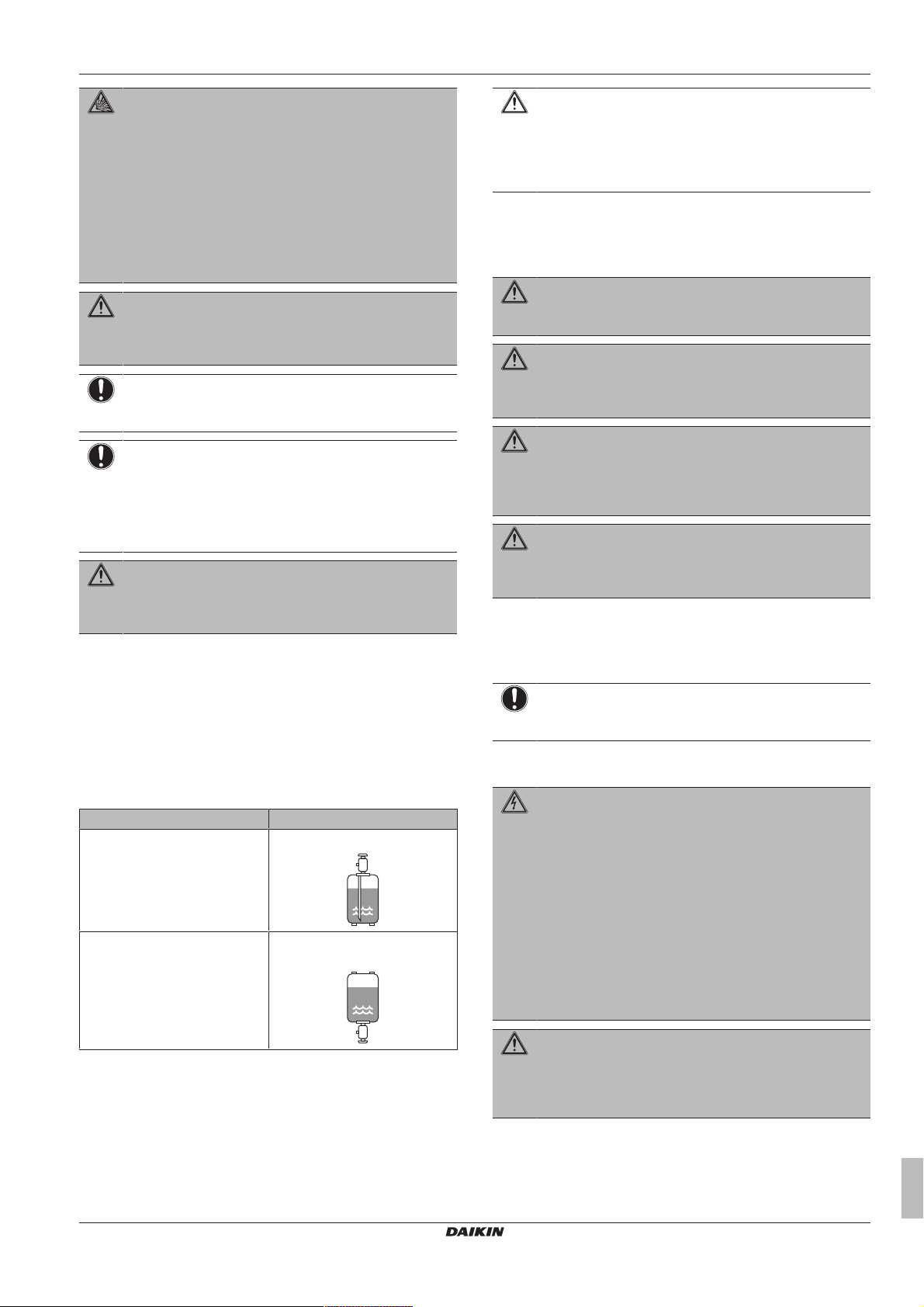
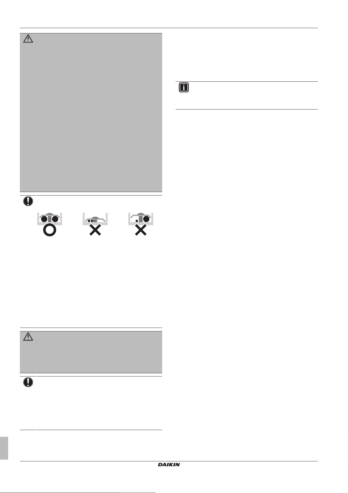
▪ Charge the liquid refrigerant as follows:
If Then
A siphon tube is present
(i.e., the cylinder is marked with
"Liquid filling siphon attached")
A siphon tube is NOT present Charge with the cylinder upside
Charge with the cylinder upright.
down.
CAUTION
When the refrigerant charging procedure is done or when
pausing, close the valve of the refrigerant tank
immediately. If the valve is NOT closed immediately,
remaining pressure might charge additional refrigerant.
Possible consequence: Incorrect refrigerant amount.
1.3.4 Brine
If applicable. See the installation manual or installer reference guide
of your application for more information.
WARNING
The selection of the brine MUST be in accordance with the
applicable legislation.
WARNING
Take sufficient precautions in case of brine leakage. If
brine leaks, ventilate the area immediately and contact
your local dealer.
WARNING
The ambient temperature inside the unit can get much
higher than that of the room, e.g. 70°C. In case of a brine
leak, hot parts inside the unit can create a hazardous
situation.
WARNING
The use and installation of the application MUST comply
with the safety and environmental precautions specified in
the applicable legislation.
1.3.5 Water
If applicable. See the installation manual or installer reference guide
of your application for more information.
NOTICE
Make sure water quality complies with EU directive
98/83EC.
1.3.6 Electrical
DANGER: RISK OF ELECTROCUTION
▪ Turn OFF all power supply before removing the
switch box cover, connecting electrical wiring or
touching electrical parts.
▪ Disconnect the power supply for more than 1 minute,
and measure the voltage at the terminals of main circuit
capacitors or electrical components before servicing.
The voltage MUST be less than 50 V DC before you
can touch electrical components. For the location of the
terminals, see the wiring diagram.
▪ Do NOT touch electrical components with wet hands.
▪ Do NOT leave the unit unattended when the service
cover is removed.
▪ Open refrigerant cylinders slowly.
▪ Charge the refrigerant in liquid form. Adding it in gas form may
prevent normal operation.
LRMEQ3+4BY1
Air-cooled refrigeration condensing unit
4P500362-1 – 2018.04
WARNING
If NOT factory installed, a main switch or other means for
disconnection, having a contact separation in all poles
providing full disconnection under overvoltage category III
condition, MUST be installed in the fixed wiring.
Installer and user reference guide
5
2 About the documentation
WARNING
▪ ONLY use copper wires.
▪ Make sure the field wiring complies with the applicable
legislation.
▪ All field wiring MUST be performed in accordance with
the wiring diagram supplied with the product.
▪ NEVER squeeze bundled cables and make sure they
do NOT come in contact with the piping and sharp
edges. Make sure no external pressure is applied to the
terminal connections.
▪ Make sure to install earth wiring. Do NOT earth the unit
to a utility pipe, surge absorber, or telephone earth.
Incomplete earth may cause electrical shock.
▪ Make sure to use a dedicated power circuit. NEVER
use a power supply shared by another appliance.
▪ Make sure to install the required fuses or circuit
breakers.
▪ Make sure to install an earth leakage protector. Failure
to do so may cause electric shock or fire.
▪ When installing the earth leakage protector, make sure
it is compatible with the inverter (resistant to high
frequency electric noise) to avoid unnecessary opening
of the earth leakage protector.
NOTICE
Precautions when laying power wiring:
▪ Do NOT connect wiring of different thicknesses to the
power terminal block (slack in the power wiring may
cause abnormal heat).
▪ When connecting wiring which is the same thickness,
do as shown in the figure above.
▪ For wiring, use the designated power wire and connect
firmly, then secure to prevent outside pressure being
exerted on the terminal board.
▪ Use an appropriate screwdriver for tightening the
terminal screws. A screwdriver with a small head will
damage the head and make proper tightening
impossible.
▪ Over-tightening the terminal screws may break them.
2 About the documentation
2.1 About this document
Target audience
Authorised installers + end users
INFORMATION
This appliance is intended to be used by expert or trained
users in shops, in light industry and on farms, or for
commercial use by lay persons.
Documentation set
This document is part of a documentation set. The complete set
consists of:
▪ General safety precautions:
▪ Safety instructions that you must read before installing
▪ Format: Paper (in the box of the outdoor unit)
▪ Outdoor unit installation and operation manual:
▪ Installation and operation instructions
▪ Format: Paper (in the box of the outdoor unit)
▪ Installer and user reference guide:
▪ Preparation of the installation, reference data,…
▪ Detailed step-by-step instructions and background information
for basic and advanced usage
▪ Format: Digital files on http://www.daikineurope.com/support-
and-manuals/product-information/
Latest revisions of the supplied documentation may be available on
the regional Daikin website or via your dealer.
The original documentation is written in English. All other languages
are translations.
Technical engineering data
▪ A subset of the latest technical data is available on the regional
Daikin website (publicly accessible).
▪ The full set of latest technical data is available on the Daikin
extranet (authentication required).
WARNING
▪ After finishing the electrical work, confirm that each
electrical component and terminal inside the electrical
components box is connected securely.
▪ Make sure all covers are closed before starting up the
unit.
NOTICE
Only applicable if the power supply is three‑phase, and the
compressor has an ON/OFF starting method.
If there exists the possibility of reversed phase after a
momentary black out and the power goes on and off while
the product is operating, attach a reversed phase
protection circuit locally. Running the product in reversed
phase can break the compressor and other parts.
Installer and user reference guide
6
Air-cooled refrigeration condensing unit
LRMEQ3+4BY1
4P500362-1 – 2018.04
For the installer
21
a
1×
b
1×
c
1×
d
1×
a
1×
b
1×
c
1×
d
1×
e
1×
f
1×
g
1×
3 About the box
3.1 Overview: About the box
This chapter describes what you have to do after the box with the
outdoor unit is delivered on-site.
It contains information about:
▪ Unpacking and handling the units
▪ Removing the accessories from the units
▪ Removing the transportation stay
Keep the following in mind:
▪ At delivery, the unit MUST be checked for damage. Any damage
MUST be reported immediately to the carrier's claims agent.
▪ Bring the packed unit as close as possible to its final installation
position to prevent damage during transport.
▪ Prepare the path along which you want to bring the unit inside in
advance.
▪ When handling the unit, take into account the following:
3 About the box
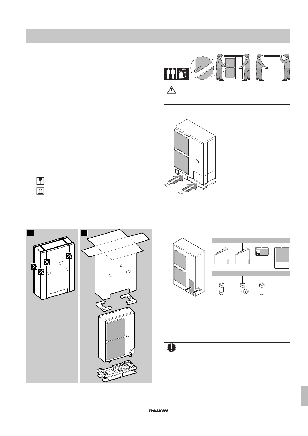
CAUTION
To avoid injury, do NOT touch the air inlet or aluminium
fins of the unit.
Forklift. As long as the unit remains on its pallet, you can also use a
forklift.
Fragile, handle the unit with care.
Keep the unit upright in order to avoid compressor
damage.
3.2 Outdoor unit
3.2.1 To unpack the outdoor unit
3.2.3 To remove the accessories from the outdoor unit
1 Remove the service cover. See "6.2.2 To open the outdoor
unit"on page14.
2 Remove the accessories.
a General safety precautions
b Outdoor unit installation and operation manual
c Fluorinated greenhouse gases label
d Multilingual fluorinated greenhouse gases label
e Gas piping accessory 1 (Ø15.9mm to 19.1mm)
f Gas piping accessory 2 (Ø19.1mm)
g Gas piping accessory 3 (Ø19.1mm)
3.2.2 To handle the outdoor unit
Carry the unit slowly as shown:
LRMEQ3+4BY1
Air-cooled refrigeration condensing unit
4P500362-1 – 2018.04
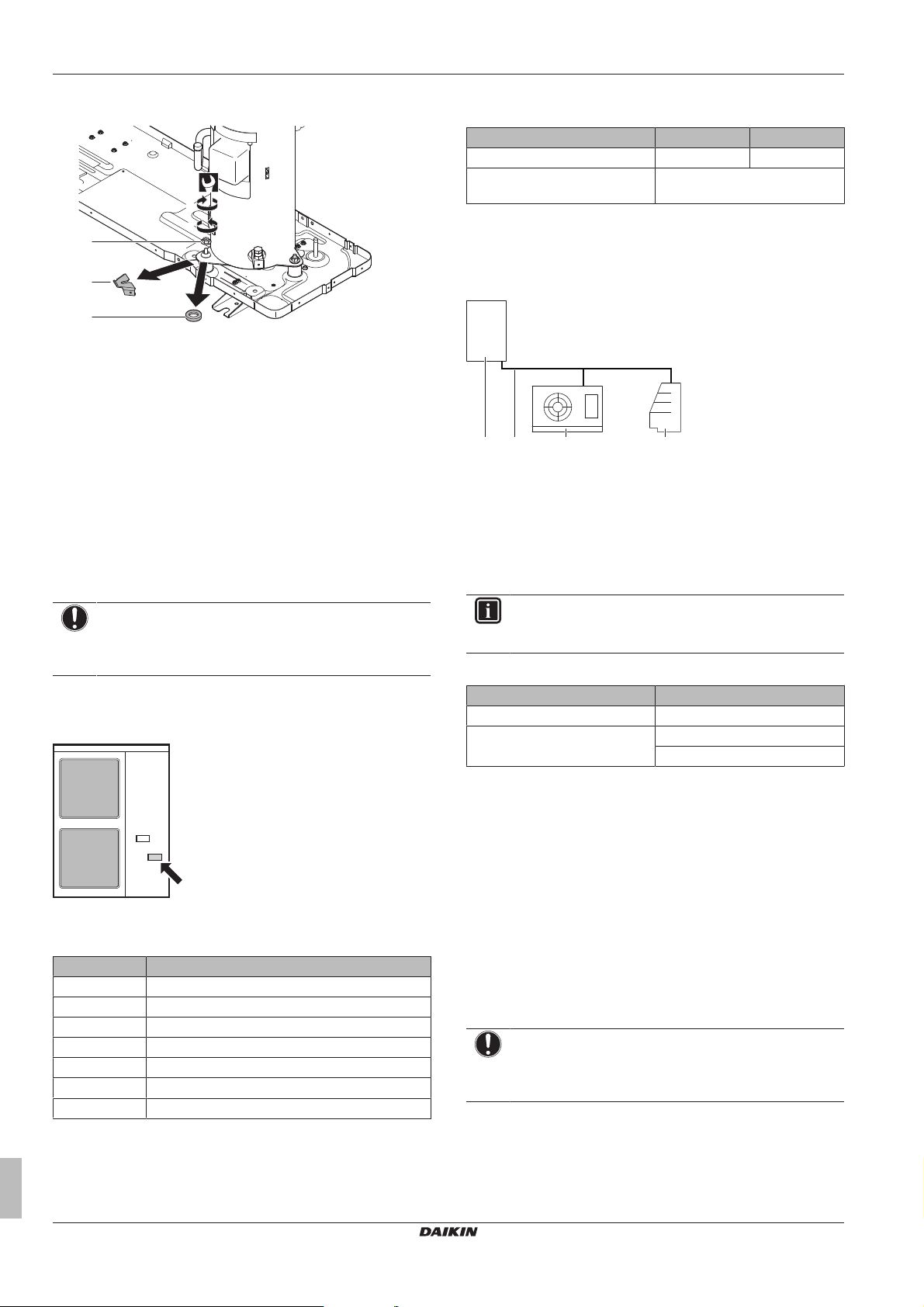
3.2.4 To remove the transportation stay
NOTICE
If the unit is operated with the transportation stay attached,
abnormal vibration or noise may be generated.
The compressor transportation stay must be removed. It is installed
under the compressor leg in order to protect the unit during
transport. Proceed as shown in the figure and procedure below.
1 Remove the nut (a) of the compressor mounting bolt.
2 Remove and discard the transportation stay (b).
3 Remove and discard the washer (c).
Installer and user reference guide
7
4 About the units
(10.1 N·m)
2
a
b
c
4
3
1
cb da
4 Re-install the nut (a) of the compressor mounting bolt and
tighten to 10.1N•m of torque.
4 About the units
4.1 Overview: About the units
This chapter contains information about:
▪ Identification of the outdoor unit.
▪ Where the outdoor unit fits in the system layout.
▪ Possible options for the outdoor unit.
▪ With which indoor units you can combine the outdoor units.
This unit is intended for outdoor installation and aimed for air to air
cooling applications.
Specification LRMEQ3 LRMEQ4
Capacity (cooling)
Ambient design temperature
(cooling)
(a)
(a) Capacity measured at the following conditions: ambient
temperature 32°C, evaporating temperature –10°C,
superheat 10K.
5.90kW 8.40kW
–20~43°CDB
4.4 System layout
a Outdoor unit (ZEAS condensing unit)
b Refrigerant piping
c Indoor unit (Blower coil)
d Indoor unit (Showcase)
4.5 Combining units and options
4.2 Identification
NOTICE
When installing or servicing several units at the same time,
make sure NOT to switch the service panels between
different models.
4.2.1 Identification label: Outdoor unit
Location
Model identification
Example: LR ME Q 4 B Y1 [*]
Code Explanation
LR ZEAS condensing unit
ME Medium temperature refrigeration
Q Refrigerant R410A
3+4 Capacity class
B Model series
Y1 Power supply
[*] Minor model change indication
4.3 About the outdoor unit
This installation manual concerns the ZEAS condensing unit.
Installer and user reference guide
8
4.5.1 Possible options for the outdoor unit
INFORMATION
Refer to the technical engineering data for the latest option
names.
Refrigerant branching kit
Description Model name
Refnet header KHRQ22M29H
Refnet joint KHRQ22M20T
KHRQ22M29T9
Modbus communication box (BRR9A1V1)
Interface that provides a two-way communication possibility with
third-party monitoring systems (BMS), via Modbus. Allows remote
access to all operating parameters, while at the same time provides
the possibility to control the refrigeration units from a distance:
setting the target evaporating temperature, resetting error codes, …
PC configurator cable (EKPCCAB)
You can make several commissioning field settings through a
personal computer interface. For this option EKPCCAB is required
which is a dedicated cable to communicate with the outdoor unit.
The user interface software is available on http://
www.daikineurope.com/support-and-manuals/software-downloads/.
4.5.2 About the indoor units
NOTICE
To be sure your system setup (outdoor unit+indoor unit(s))
will work, you have to consult the latest technical
engineering data for ZEAS condensing unit.
The ZEAS condensing unit can be combined with several types of
third party indoor units and is intended for R410A use only.
When installing indoor units, mind the following:
▪ Expansion valve. Install an R410A expansion valve on each
indoor unit. Insulate the feeler block of the expansion valve.
LRMEQ3+4BY1
Air-cooled refrigeration condensing unit
4P500362-1 – 2018.04
5 Preparation
≥1500
≥1500
(mm)
≥1500≥1500
≥1500≥1500
a b c ga b e f a b
d
INFORMATION
▪ Install either a mechanical thermostatic expansion
valve, or an electronic expansion valve (proportional or
pulse type).
▪ When installing a pulse-type electronic expansion
valve, make sure to protect the piping from pressure
waves caused by the opening and closing of the valve.
The installation of a pulse type expansion valve is the
responsibility of the installer.
For more information, see "5.3.7To select the expansion valve" on
page13.
▪ Solenoid valve. Install an R410A solenoid valve (with an
operating differential pressure of 3.5MPa [35bar] or more) on the
primary side of the expansion valve for each indoor unit.
▪ Filter. Install a filter on the primary side of the solenoid valve for
each indoor unit. Determine the filter mesh count based on the
size specified by the solenoid valve and the expansion valve being
used.
▪ Refrigerant flow. Route the path to the indoor unit heat
exchanger so that the refrigerant flow is from top to bottom.
▪ Defrosting type. Use either off-cycle defrosting or electric heater
defrosting models. Do NOT use hot-gas defrosting models.
About reusing existing indoor heat exchangers
In some cases you may reuse existing indoor heat exchangers, in
other cases not.
Reuse NOT allowed
You may not reuse existing indoor heat exchangers in the following
cases:
▪ When the design pressure is insufficient. Minimum design
pressure = 2.5MPa or 25bar
▪ When the path to the heat exchanger has been routed so that the
flow of refrigerant is from bottom to top.
▪ When the copper piping or fan is corroded.
▪ When the heat exchanger is contaminated. Foreign materials
(including oils for fabrication) must be ≤30mg/10m.
Reuse allowed
In other cases than above, you may reuse existing indoor heat
exchangers. However, if the old condensing unit did NOT use the
same refrigerant (R410A) and the same oil (FVC68D) as the new
one, you must clean the heat exchanger tubes to remove any
residue.
If the old condensing unit did NOT use the same refrigerant (R410A)
as the new one, make sure the expansion valve is compatible with
R410A.
5.2 Preparing the installation site
Do NOT install the unit in places often used as work place. In case
of construction works (e.g. grinding works) where a lot of dust is
created, the unit MUST be covered.
Choose an installation location with sufficient space for carrying the
unit in and out of the site.
5.2.1 Installation site requirements of the outdoor unit
INFORMATION
Also read the following requirements:
▪ General installation site requirements. See the
"General safety precautions" chapter.
▪ Service space requirements. See the "Technical data"
chapter.
▪ Refrigerant piping requirements (length, height
difference). See further in this "Preparation" chapter.
INFORMATION
The sound pressure level is less than 70dBA.
CAUTION
Appliance not accessible to the general public, install it in a
secured area, protected from easy access.
This unit, both indoor and outdoor, is suitable for
installation in a commercial and light industrial
environment.
NOTICE
This equipment is compliant with Class A of EN55032/
CISPR 32. In a residential environment this equipment
may cause radio interference.
NOTICE
The equipment described in this manual may cause
electronic noise generated from radio-frequency energy.
The equipment complies to specifications that are
designed to provide reasonable protection against such
interference. However, there is no guarantee that
interference will not occur in a particular installation.
It is therefore recommended to install the equipment and
electric wires keeping proper distances away from stereo
equipment, personal computers, etc.
5 Preparation
5.1 Overview: Preparation
This chapter describes what you have to do and know before going
on-site.
It contains information about:
▪ Preparing the installation site
▪ Preparing the refrigerant piping
▪ Preparing the electrical wiring
LRMEQ3+4BY1
Air-cooled refrigeration condensing unit
4P500362-1 – 2018.04
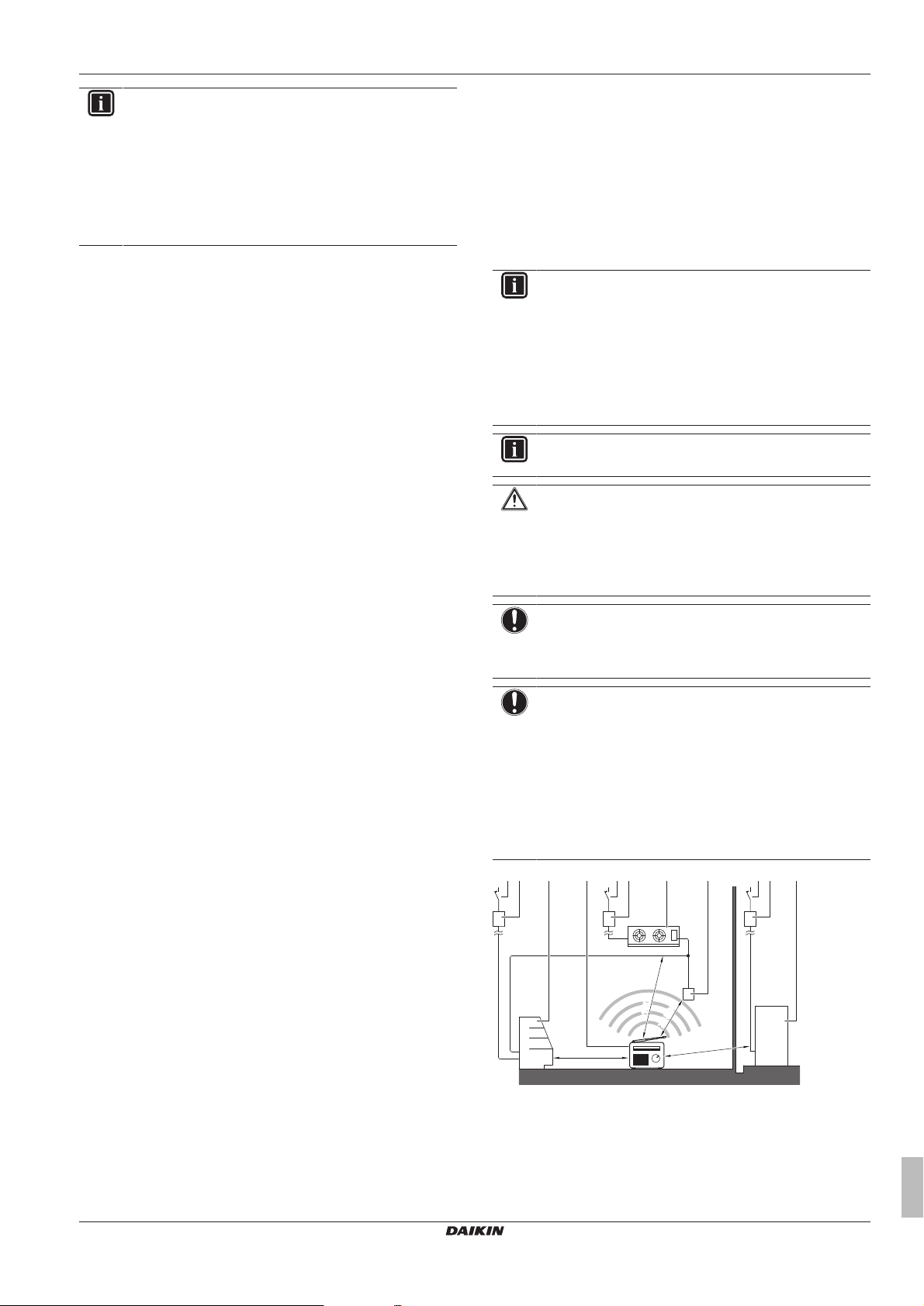
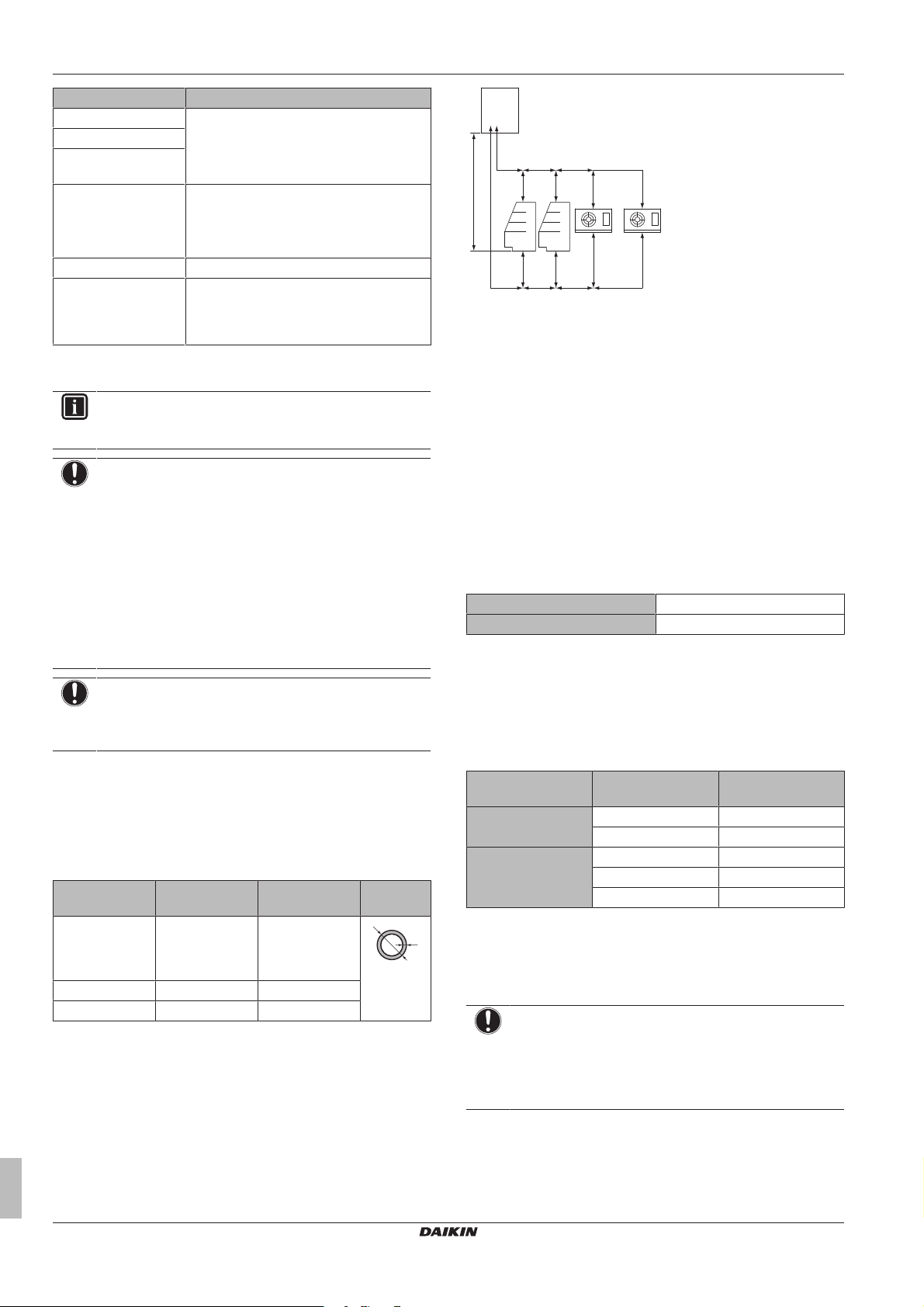
a Earth leakage protector
b Fuse
c Indoor unit (Showcase)
d Personal computer or radio
e Indoor unit (Blower coil)
f User interface
g Outdoor unit
Installer and user reference guide
9
5 Preparation
b
c
a
a
b
c
d
c
d
a
a
a
b
a
b
c
c
d
In places with weak reception, keep distances of 3 m or more to
avoid electromagnetic disturbance of other equipment and use
conduit tubes for power and transmission lines.
▪ Select a place where rain can be avoided as much as possible.
▪ Take care that in the event of a water leak, water cannot cause
any damage to the installation space and surroundings.
▪ Choose a location where the hot/cold air discharged from the unit
or the operation noise, will NOT disturb anyone.
▪ Heat exchanger fins are sharp and injury is possible. Choose an
installation location where there is no risk for injury (especially in
areas where children play).
Do NOT install the unit in the following places:
▪ Sound sensitive areas (e.g. near a bedroom), so that the
operation noise will cause no trouble.
Note: If the sound is measured under actual installation
conditions, the measured value might be higher than the sound
pressure level mentioned in Sound spectrum in the data book due
to environmental noise and sound reflections.
▪ In places where a mineral oil mist, spray or vapour may be
present in the atmosphere. Plastic parts may deteriorate and fall
off or cause water leakage.
It is NOT recommended to install the unit in the following places
because it may shorten the life of the unit:
▪ Where the voltage fluctuates a lot
▪ In vehicles or vessels
▪ Where acidic or alkaline vapour is present
Seaside installation. Make sure the outdoor unit is NOT directly
exposed to sea winds. This is to prevent corrosion caused by high
levels of salt in the air, which might shorten the life of the unit.
▪ deterioration of the operational capacity;
▪ disruption of operation due to decrease of low pressure or
increase of high pressure;
▪ a broken fan (if a strong wind blows continuously on the fan, it
may start rotating very fast, until it breaks).
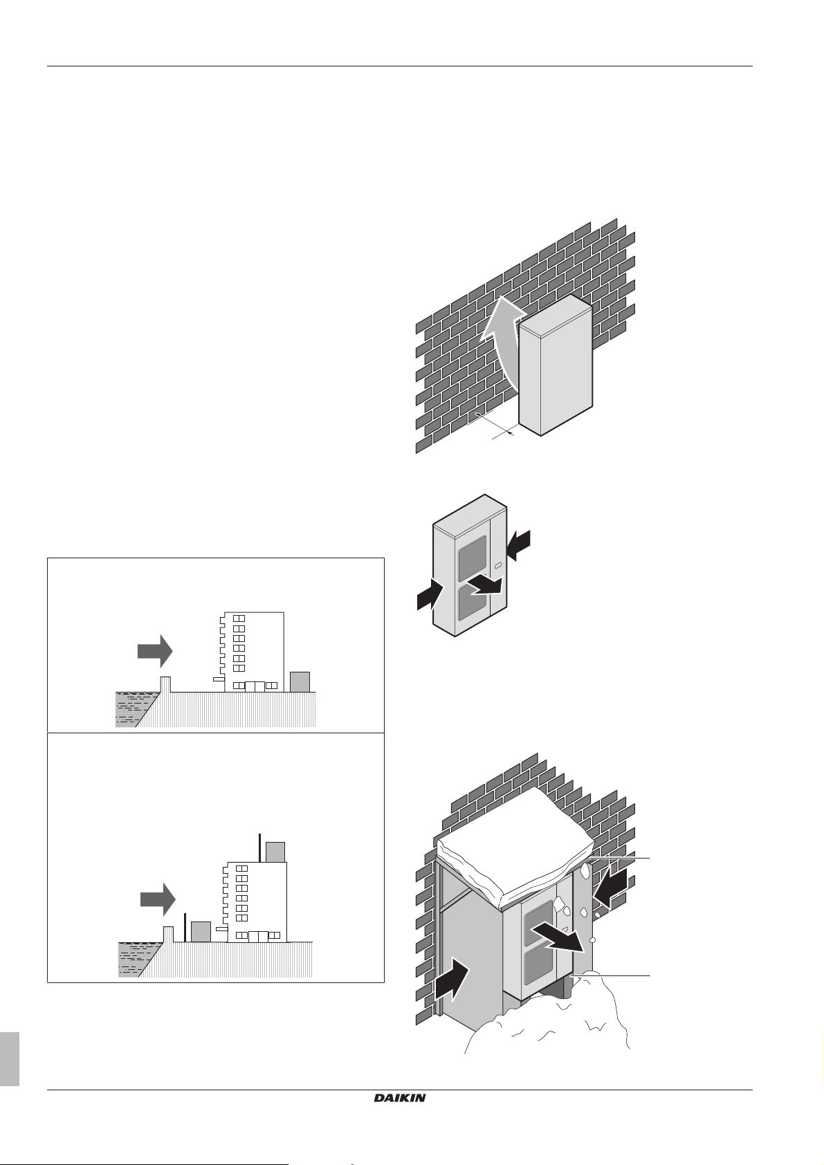
It is recommended to install a baffle plate when the air outlet is
exposed to wind.
Turn the air outlet side towards the building's wall, fence or screen.
a Make sure there is enough installation space
Set the air outlet side at a right angle to the direction of the wind.
Install the outdoor unit away from direct sea winds.
Example: Behind the building.
If the outdoor unit is exposed to direct sea winds, install a
windbreaker.
▪ Height of windbreaker≥1.5×height of outdoor unit
▪ Mind the service space requirements when installing the
windbreaker.
a Prevailing wind direction
b Air outlet
5.2.2 Additional installation site requirements of the outdoor unit in cold climates
Protect the outdoor unit against direct snowfall and take care that the
outdoor unit is NEVER snowed up.
a Sea wind
b Building
c Outdoor unit
d Windbreaker
Strong winds (≥18 km/h) blowing against the outdoor unit’s air outlet
causes short circuit (suction of discharge air). This may result in:
Installer and user reference guide
10
a Snow cover or shed
b Pedestal (minimum height = 150mm)
LRMEQ3+4BY1
Air-cooled refrigeration condensing unit
4P500362-1 – 2018.04
5 Preparation
a b
a b
c Prevailing wind direction
d Air outlet
5.2.3 Securing safety against refrigerant leaks
About safety against refrigerant leaks
The installer and system specialist shall secure safety against
leakage according to local regulations or standards. The following
standards may be applicable if local regulations are not available.
This system uses R410A as refrigerant. R410A itself is an entirely
safe non-toxic, non-combustible refrigerant. Nevertheless care must
be taken to ensure that the system is installed in a room which is
sufficiently large. This assures that the maximum concentration level
of refrigerant gas is not exceeded, in the unlikely event of major leak
in the system and this in accordance to the local applicable
regulations and standards.
About the maximum concentration level
The maximum charge of refrigerant and the calculation of the
maximum concentration of refrigerant is directly related to the
humanly occupied space in to which it could leak.
The unit of measurement of the concentration is kg/m3 (the weight in
kg of the refrigerant gas in 1m3 volume of the occupied space).
Compliance to the local applicable regulations and standards for the
maximum allowable concentration level is required.
According to the appropriate European Standard, the maximum
allowed concentration level of refrigerant to a humanly space for
R410A is limited to 0.44kg/m3.
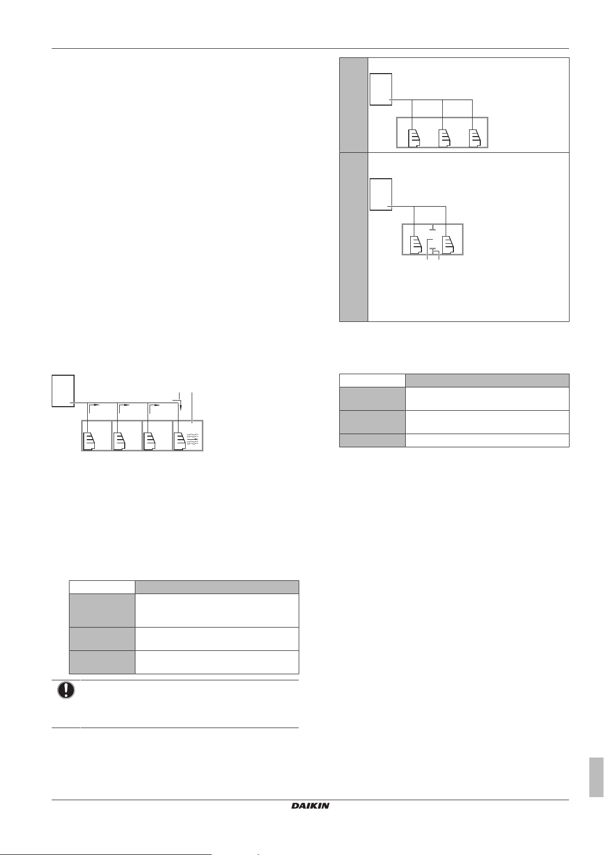
a Direction of the refrigerant flow
b Room where refrigerant leak has occurred (outflow of all
the refrigerant from the system)
Pay special attention to places, such as basements etc., where
refrigerant can stay, since refrigerant is heavier than air.
D When there are no smaller room divisions:
E When there is a room division that has an opening
sufficiently large to permit free air flow.
a Opening between the rooms. In case there is a door
the openings above and below the door each must be
equivalent in size to 0.15% or more of the floor area.
b Room division
3 Calculate the refrigerant density using the results of the
calculations in steps 1 and 2 above. If the result of the above
calculation exceeds the maximum concentration level, a
ventilation opening to the adjacent room shall be made.
Formula F/G≤H
F Total volume of refrigerant in the refrigerant
system
G Size (m3) of smallest room in which there is
an indoor unit installed
H Maximum concentration level (kg/m3)
4 Calculate the refrigerant density taking the volume of the room
where the indoor unit is installed and the adjacent room. Install
ventilation openings in the door of adjacent rooms until the
refrigerant density is smaller than the maximum concentration
level.
To check the maximum concentration level
Check the maximum concentration level in accordance with steps 1
to 4 below and take whatever action is necessary to comply.
1 Calculate the amount of refrigerant (kg) charged to each system
separately.
Formula A+B=C
A Amount of refrigerant in a single unit system
(amount of refrigerant with which the system
is charged before leaving the factory)
B Additional charging amount (amount of
refrigerant added locally)
C Total amount of refrigerant (kg) in the
system
NOTICE
Where a single refrigerant facility is divided into 2 entirely
independent refrigerant systems, use the amount of
refrigerant with which each separate system is charged.
2 Calculate the volume of the room (m3) where the indoor unit is
installed. In a case such as the following, calculate the volume
of (D), (E) as a single room or as the smallest room.
LRMEQ3+4BY1
Air-cooled refrigeration condensing unit
4P500362-1 – 2018.04
5.3 Preparing refrigerant piping
5.3.1 About reusing existing piping
In some cases you may reuse existing piping, in other cases not.
Reuse not allowed
You may not reuse existing piping in the following cases:
▪ When the compressor in the old installation had problems
(example: breakdown). Possible consequence: oxidised coolant
oil, scale residue and other adverse effects.
▪ When the indoor and outdoor units were disconnected from the
piping for a long time. Possible consequence: water and dirt in
the piping.
▪ When the copper piping is corroded.
Reuse allowed
In other cases than above, you may reuse existing piping but keep
the following in mind:
Installer and user reference guide
11
5 Preparation
t
Ø
F
A
1
2 3 3
d1
e
B
d2
C
c
D1
E
f
D2
ba
H
2
Item Description
Piping diameter Must comply with requirements. See
Piping material
Piping length and
height difference
Piping insulation If deteriorated, must be replaced.
Welded connections Must be checked for gas leaks.
Cleaning piping If the old condensing unit did NOT use the
5.3.2 Refrigerant piping requirements
INFORMATION
Also read the precautions and requirements in the
"General safety precautions" chapter.
NOTICE
The refrigerant R410A requires strict cautions for keeping
the system clean, dry and tight.
▪ Clean and dry: foreign materials (including mineral oils
or moisture) should be prevented from getting mixed
into the system.
▪ Tight: R410A does not contain any chlorine, does not
destroy the ozone layer, and does not reduce earth's
protection against harmful ultraviolet radiation. R410A
can contribute slightly to the greenhouse effect if it is
released. Therefore pay special attention to check the
tightness of the installation.
NOTICE
The piping and other pressure-containing parts shall be
suitable for refrigerant. Use phosphoric acid deoxidised
seamless copper for refrigerant.
▪ Foreign materials inside pipes (including oils for fabrication) must
be ≤30mg/10m.
5.3.3 Refrigerant piping material
▪ Piping material: Phosphoric acid deoxidised seamless copper.
▪ Piping temper grade and thickness:
Outer diameter
(Ø)
6.4mm (1/4")
9.5mm (3/8")
12.7mm (1/2")
15.9mm (5/8") Annealed (O) ≥0.99mm
19.1mm (3/4") Half hard (1/2H) ≥0.80mm
(a) Depending on the applicable legislation and the unit's
5.3.4 To select the piping size
Determine the proper size using the following tables and reference
figure (only for indication).
"5.3.2Refrigerant piping requirements"on
page12.
Must comply with requirements. See
"6.6To insulate the refrigerant piping"on
page21.
same refrigerant (R410A) and the same oil
(FVC68D) as the new one, you must clean
the piping to remove any residue.
Temper grade Thickness (t)
(a)
Annealed (O) ≥0.80mm
maximum working pressure (see "PS High" on the unit
name plate), larger piping thickness might be required.
1 Outdoor unit
2 Indoor unit (Showcase)
3 Indoor unit (Blower coil)
A~F Liquid piping
a~f Gas piping
H Height difference outdoor-indoor
In case the required pipe sizes (inch sizes) are not available, it is
also allowed to use other diameters (mm sizes), taken the following
into account:
▪ Select the pipe size nearest to the required size.
▪ Use the suitable adapters for the change-over from inch tomm
pipes (field supply).
▪ The additional refrigerant calculation has to be adjusted as
mentioned in "6.7.3 To determine the additional refrigerant
amount"on page22.
A/a: Piping between outdoor unit and piping branching
Liquid piping Ø9.5 mm
Gas piping Ø19.1 mm
(a) Same diameter as the connection on the outdoor unit.
(b) Use the accessory piping to adapt the diameter of the
outdoor unit stop valve (Ø15.9 mm) to that of the field
piping (Ø19.1 mm).
(a)
(b)
B+C/b+c: Piping between piping branching
Use diameters depending on the total capacity of the indoor units
connected downstream.
Capacity Piping outer
diameter
Liquid piping <4.0kW Ø6.4mm
4.0≤x<8.4kW Ø9.5mm
Gas piping <1.0kW Ø9.5mm
1.0≤x<6.0kW Ø12.7mm
6.0≤x<8.4kW Ø15.9mm
D~F/d~f: Piping between piping branching and indoor unit
Use the same diameters as the connections (liquid, gas) on the
indoor units.
NOTICE
If only 1 indoor unit is connected to the outdoor unit, and
the connections on the outdoor unit are different from
those on the indoor unit, then use the same piping
diameter as the connections on the outdoor unit, and install
suitable adapters as near to the indoor unit as possible.
5.3.5 To select refrigerant branch kits
For refrigerant piping branching, it is allowed to use T-joints, Y-joints,
refnet joints, and refnet headers. It is possible to use a refrigerant
branching option kit from the table below.
Installer and user reference guide
12
Air-cooled refrigeration condensing unit
LRMEQ3+4BY1
4P500362-1 – 2018.04
5 Preparation
REMOTE
OFF
ON
Description Model name
Refnet header
Refnet joint
(a)
(b)
KHRQ22M29H
KHRQ22M20T
KHRQ22M29T9
(a) Do NOT connect 2 or more headers in series. For the gas
side choose the refnet header so that the diameter of the
header is equal to the main piping diameter or equal to one
size-up of the main piping diameter.
(b) Choose the refnet joint so that the incoming and outgoing
piping diameters match with one of the available diameters
of the refnet joint. For more information, see
"5.3.3Refrigerant piping material"on page12 and
"5.3.4To select the piping size"on page12.
INFORMATION
Maximum 8 branches can be connected to a header.
5.3.6 Refrigerant piping length and height difference
The piping lengths and height differences must comply with the
following requirements.
(see example in "5.3.4To select the piping size"on page12)
Requirement Limit
Maximum actual piping length
50m
▪ Example: a+b+c+d2≤Limit
Maximum total piping length
80m
▪ Example: a+b+c+d1+d2+e+f≤Limit
Maximum length first branch kit-indoor
30m
unit
▪ Example: b+c+d2≤Limit
Maximum height
difference outdoorindoor
Outdoor higher than
indoor
▪ Example: H≤Limit
Outdoor lower than
20m
10m
indoor
Maximum height difference indoor-indoor 5m
5.3.7 To select the expansion valve
This unit has a larger subcooling ratio for the liquid refrigerant
compared to units without a subcooling mechanism, as the liquid
refrigerant is being cooled by a double tube heat exchanger
(subcooling ratio = condensing temperature–liquid refrigerant
temperature at outdoor unit outlet).
When selecting an expansion valve for the load according to the
technical information of the expansion valve manufacturer, take into
account the subcooling ratio (K) for the liquid refrigerant in the table
below.
Subcooling ratio (K)
Te –20°C –15°C –10°C –5°C 0°C 5°C
Tc
20°C 10 9 8 7 6 5
25°C 11 10 9 8 7 6
30°C 12 11 10 9 8 7
35°C 13 12 11 10 9 8
40°C 14 13 12 11 10 9
45°C 15 14 13 12 11 10
50°C 16 15 14 13 12 11
55°C 16 15 14 13 12 11
5.4 Preparing electrical wiring
5.4.1 Safety device requirements
Power supply
The power supply must be protected with the required safety
devices, i.e. a main switch, a slow blow fuse on each phase and an
earth leakage protector in accordance with the applicable legislation.
Selection and sizing of the wiring should be done in accordance with
the applicable legislation based on the information mentioned in the
table below.
Model Minimum circuit
ampacity
LRMEQ3 6.5A 16A 3N~ 50Hz
LRMEQ4 9.1A
Remote operation switch, low-noise switch and output signals
wiring
NOTICE
Remote operation switch. The unit is factory-equipped
with an operation switch with which you can turn unit
operation ON/OFF. If you want to remotely turn outdoor
unit operation ON/OFF, a remote operation switch is
required. Use a voltage-free contact for microcurrent
(≤1 mA, 12 V DC). Connect to X2M/C+D, and set to
"Remote ".
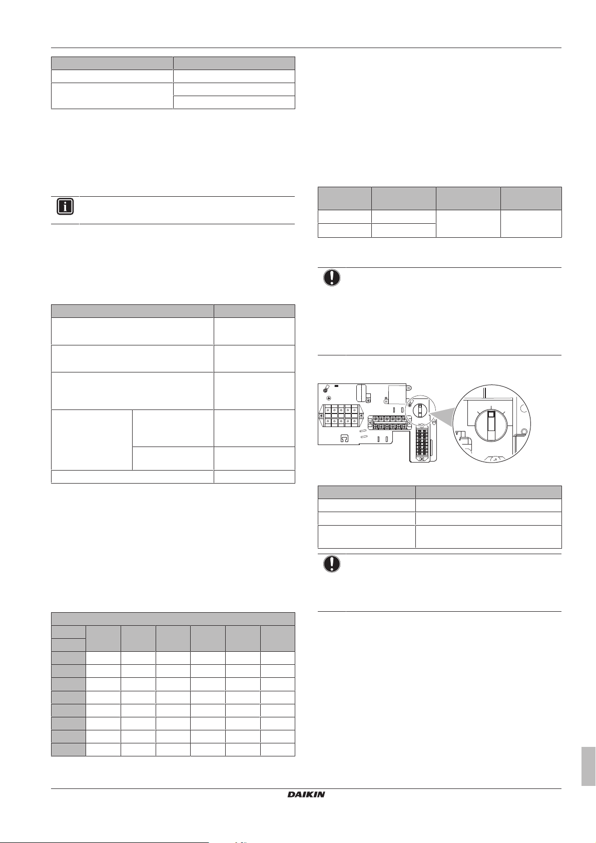
The operation switch is located in the switchbox (see illustration
below).
The operation switch can be set to the following three positions:
Operation switch setting Function
OFF Unit operation turned OFF
ON Unit operation turned ON
Remote Unit controlled (ON/OFF) with remote
NOTICE
Low-noise switch. If you want to remotely turn ON/OFF
low-noise operation (see setting [2‑18]), you must install a
low-noise switch. Use a voltage-free contact for
microcurrent (≤1mA, 12VDC). Connect to X2M/A+B.
Recommended
fuses
operation switch
Power supply
380-415V
LRMEQ3+4BY1
Air-cooled refrigeration condensing unit
4P500362-1 – 2018.04
Installer and user reference guide
13
6 Installation
1×
1
2
NOTICE
Output signals. The outdoor unit is provided with a
terminal (X3M) that can output 4 different signals. The
signal is 220~240VAC. The maximum load for all signals
is 0.5 A. The unit outputs a signal in the following
situations:
▪ C/C1: caution signal – connection recommended –
when an error occurs that does not stop unit operation.
▪ C/W1: warning signal – connection recommended –
when an error occurs that causes unit operation to
stop.
▪ R/P2: run signal – connection optional – when the
compressor is running.
▪ P1/P2: operation signal – connection mandatory –
when the indoor unit solenoid valve is being controlled.
Wiring Sheathed cable (2 wires)
Vinyl cords
0.75~1.25mm²
Maximum wiring length 130m
6 Installation
6.1 Overview: Installation
This chapter describes what you have to do and know on-site to
install the system.
Typical workflow
Installation typically consists of the following stages:
▪ Mounting the outdoor unit.
▪ Mounting the indoor units.
▪ Connecting the refrigerant piping.
▪ Checking the refrigerant piping.
▪ Charging refrigerant.
▪ Connecting the electrical wiring.
▪ Finishing the outdoor installation.
▪ Finishing the indoor installation.
INFORMATION
For installation of the indoor unit (mounting the indoor unit,
connecting the refrigerant piping to the indoor unit,
connecting the electrical wiring to the indoor unit …), see
the installation manual of the indoor unit.
6.2 Opening the units
6.2.1 About opening the units
At certain times, you have to open the unit. Example:
▪ When connecting the refrigerant piping
▪ When connecting the electrical wiring
▪ When maintaining or servicing the unit
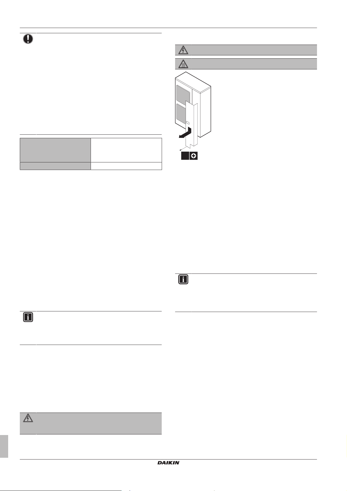
6.2.2 To open the outdoor unit
DANGER: RISK OF ELECTROCUTION
DANGER: RISK OF BURNING
6.3 Mounting the outdoor unit
6.3.1 About mounting the outdoor unit
Typical workflow
Mounting the outdoor unit typically consists of the following stages:
1 Providing the installation structure.
2 Installing the outdoor unit.
3 Preventing the unit from falling over.
4 Protecting the unit against snow and wind by installing a snow
cover and baffle plates. See "Preparing installation site" in
"5Preparation"on page9.
6.3.2 Precautions when mounting the outdoor unit
INFORMATION
Also read the precautions and requirements in the
following chapters:
▪ General safety precautions
▪ Preparation
6.3.3 To provide the installation structure
Check the strength and level of the installation ground so that the
unit will not cause any operating vibration or noise.
Fix the unit securely by means of foundation bolts in accordance
with the foundation drawing.
Prepare 4 sets of anchor bolts, nuts and washers (field supply) as
follows:
DANGER: RISK OF ELECTROCUTION
Do NOT leave the unit unattended when the service cover
is removed.
Installer and user reference guide
14
Air-cooled refrigeration condensing unit
LRMEQ3+4BY1
4P500362-1 – 2018.04
 Loading...