

Daikin FWG05AATNMV1, FWG08AATNMV1, FWG11AATNMV1, FWG05AAFNMV1, FWG08AAFNMV1 Installation manuals
...
INSTALLATION
MANUAL
CEILING CASSETTE
CHILLED WATER FAN COIL UNIT
MODELS
FWG05AATNMV1
FWG08AATNMV1
FWG11AATNMV1
FWG05AAFNMV1
Installation Manual
Chilled Water Fan Coil Units
Installationsmanual
Kylda vattenfl äktspolenheter
English
Svenska
FWG08AAFNMV1
FWG11AAFNMV1
IM-CKEW(DC)-1013(5)-DAIKIN
Part No.:R08019039336E

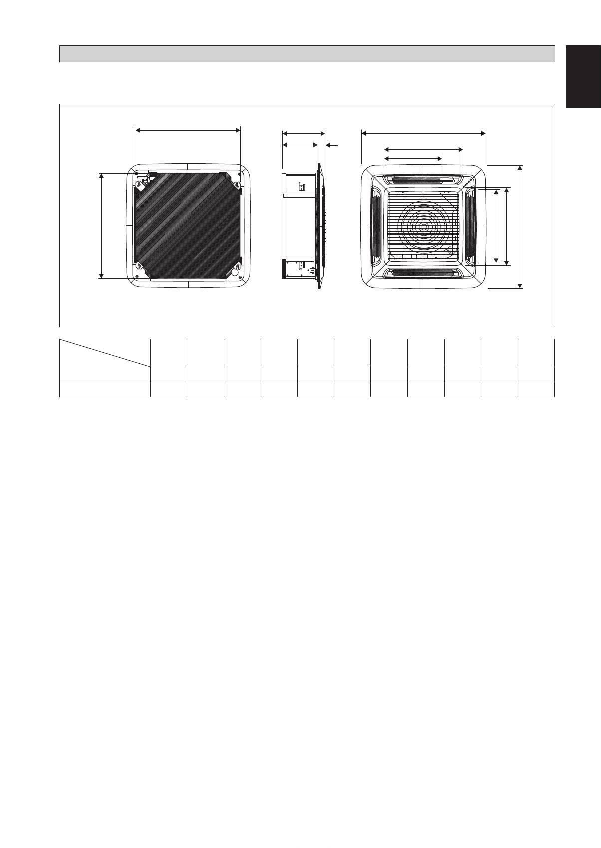
OUTLINE AND DIMENSIONS
Indoor Unit FWG05/08/11AAT(F) Series
• (With Wireless Remote Control & With Wired Remote Control)
English
A
Dimension
Model
FWG05/08AAT(F)
FWG11AAT(F)
B
C
D
E
F
H
K
I
J
G
All dimensions are in mm
ABCDEFGHI JK
820 820 340 300 40 990 990 627 627 607 430
820 820 375 335 40 990 990 627 627 607 430
Original Instruction
1-1
INSTALLATION MANUAL
This manual provides the procedures of installation to ensure a safe and good standard of operation for the air conditioner unit.
Special adjustment may be necessary to suit local requirement.
Before using your air conditioner, please read this instruction manual carefully and keep it for future reference.
This appliance is intended to be used by expert or trained users in shops, in light industry and on farms, or for commercial use by
lay persons.
This appliance is not intended for use by persons, including children, with reduced physical, sensory or mental capabilities, or lack
of experience and knowledge, unless they have been given supervision or instruction concerning use of the appliance by a person
responsible for their safety.
Children should be supervised to ensure that they do not play with the appliance.
SAFETY PRECAUTIONS
WARNING CAUTION
• Installation and maintenance should be performed by qualified
persons who are familiar with local code and regulation, and
experienced with this type of appliance.
• All field wiring must be installed in accordance with the
national wiring regulation.
• Ensure that the rated voltage of the unit corresponds to that
of the name plate before commencing wiring work according
to the wiring diagram.
• The unit must be GROUNDED to prevent possible hazard
due to insulation failure.
• All electrical wiring must not touch the refrigerant piping, or
any moving parts of the fan motors.
• Confirm that the unit has been switched OFF before installing
or servicing the unit.
• Disconnect from the main power supply before servicing the
air conditioner unit.
• DO NOT pull out the power cord when the power is ON.
This may cause serious electrical shocks which may result
in fire hazards.
• Keep the indoor and outdoor units, power cable and
transmission wiring, at least 1m from TVs and radios, to
prevent distorted pictures and static. {Depending on the type
and source of the electrical waves, static may be heard even
when more than 1m away}.
Please take note of the following important points when installing.
• Ensure that the drainage piping is connected properly.
If the drainage piping is not connected properly, it may
cause water leakage which will dampen the furniture.
• Ensure that the unit’s panel is closed after service or
installation.
Unsecured panels will cause the unit to operate noisily.
• Sharp edges and coil surfaces are potential locations which
may cause injury hazards.
Avoid from being in contact with these places.
• Before turning off the power supply set the remote
controller’s ON/OFF switch to the “OFF” position to
prevent the nuisance tripping of the unit. If this is not done,
the unit’s fans will start turning automatically when power
resumes, posing a hazard to service personnel or the user.
• Do not install the units at or near doorway.
• Do not operate any heating apparatus too close to the
air conditioner unit or use in room where mineral oil, oil
vapour or oil steam exist, this may cause plastic part to melt
or deform as a result of excessive heat or chemical reaction.
• When the unit is used in kitchen, keep flour away from
going into suction of the unit.
• This unit is not suitable for factory used where cutting
oil mist or iron powder exist or voltage fluctuates greatly.
• Do not install the units at area like hot spring or oil refinery
plant where sulphide gas exists.
• Ensure the color of wires of the outdoor unit and the
terminal markings are same to the indoors respectively.
• IMPORTANT : DO NOT INSTALL OR USE THE AIR
CONDITIONER UNIT IN A LAUNDRY ROOM.
• Don’t use joined and twisted wires for incoming power
supply.
• The equipment is not intended for use in a potentially
explosive atmosphere.
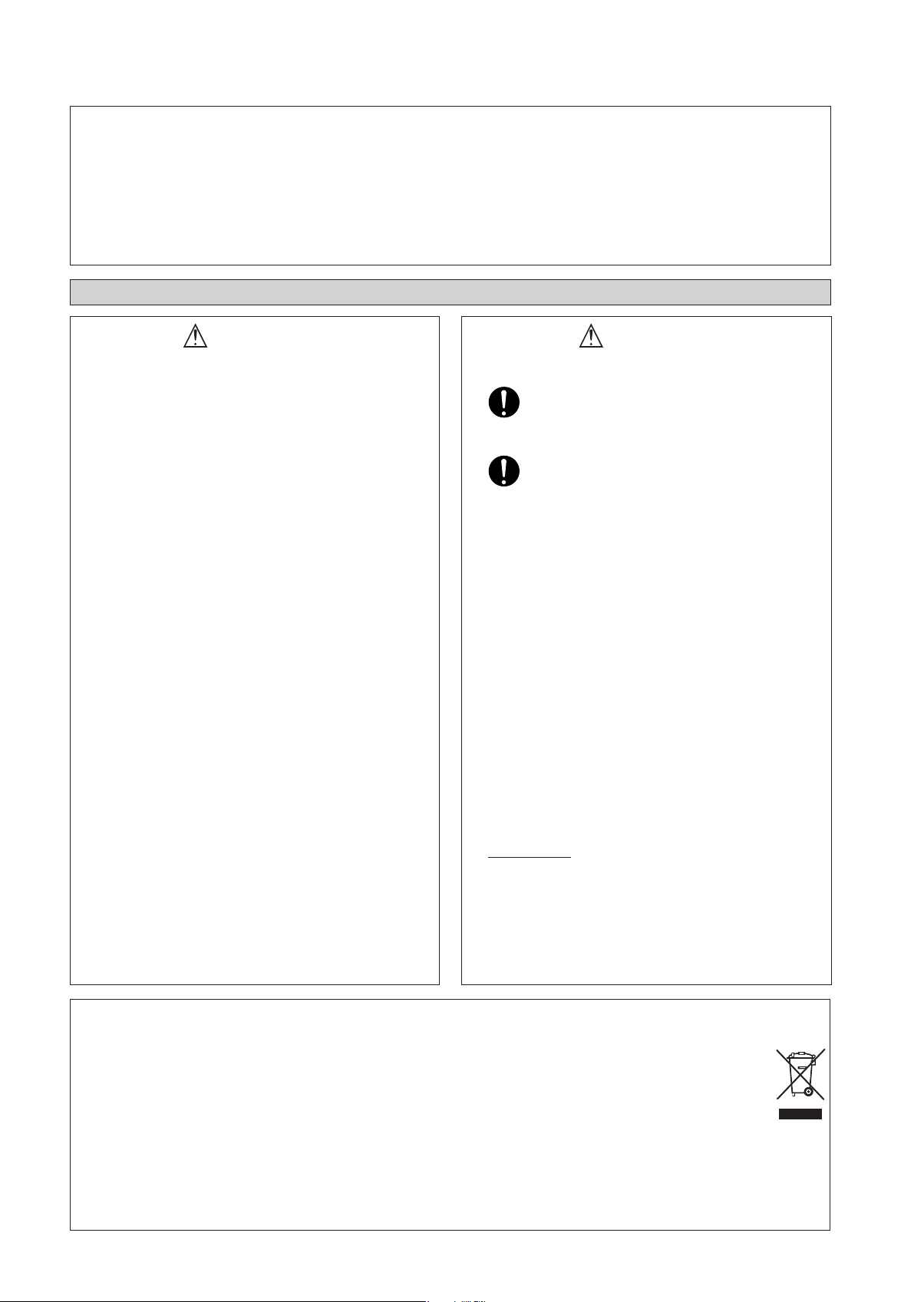
NOTICE
Disposal requirement [For European Union (EU) only]
Your air conditioning product is marked with this symbol. This means that electrical and electronic products shall
not be mixed with unsorted household waste.
Do not try to dismantle the system yourself: the dismantling of the air conditioning system, treatment of the
refrigerant, of oil and other parts must be done by a qualified installer in accordance with relevant local and national
legislation.
Air conditioners must be treated at a specialized treatment facility for re-use, recycling and recovery. By ensuring
correct disposal, you will help to prevent potential negative consequences for the environment and human health.
Please contact the installer or local authority for more information.
Batteries must be removed from the remote controller and disposed of separately in accordance with relevant local
and national legislation.
1-2
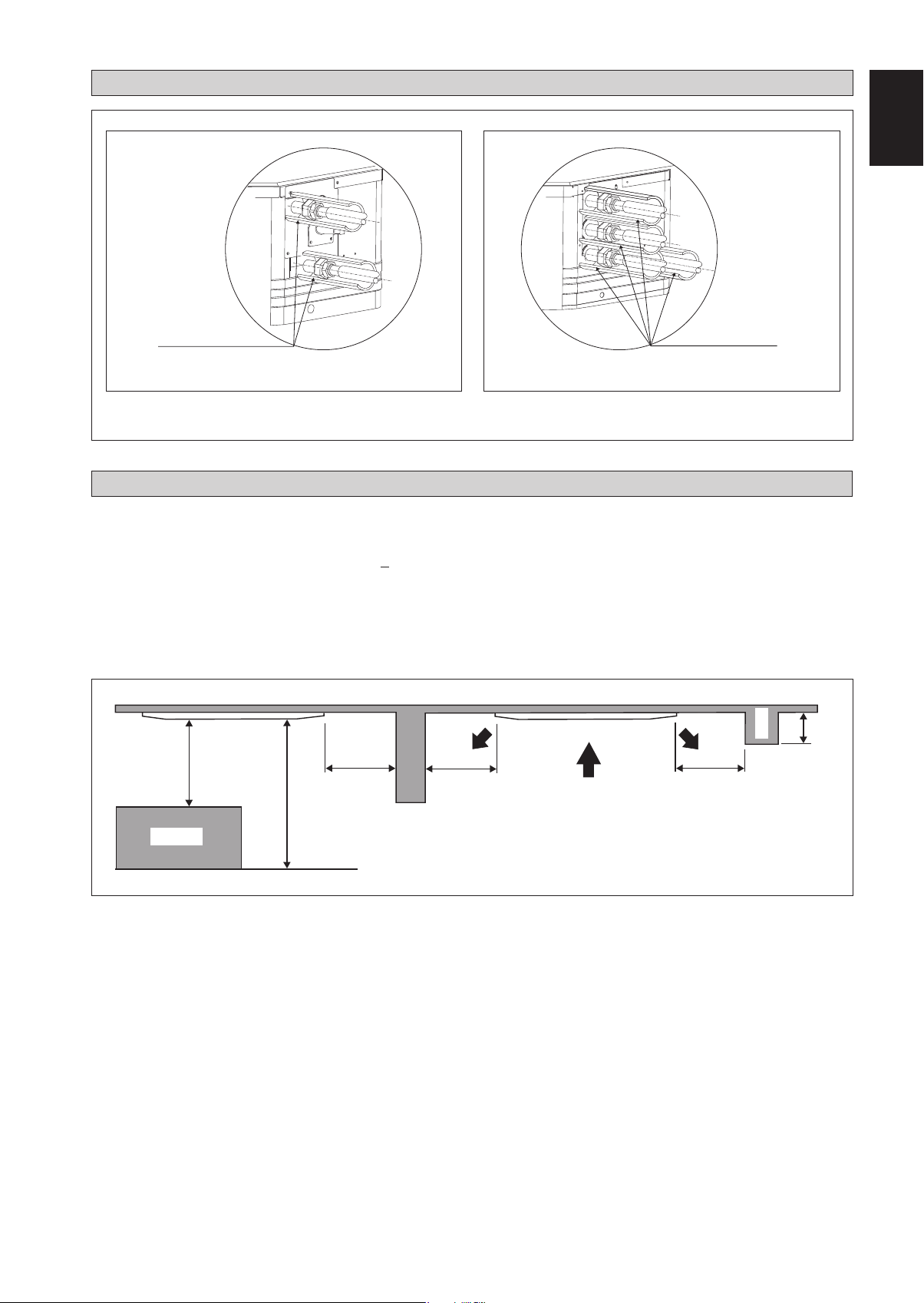
INSTALLATION DIAGRAM
English
CORK TAPE FULLY INSULATED
INSULATION THROUGH OUT CHILLED WATER PIPING
INSULATION THROUGH OUT CHILLED WATER PIPING
CORK TAPE FULLY INSULATED
2 Pipes System 4 Pipes System
INSTALLATION OF THE INDOOR UNIT
1. Preliminary Site Survey
Be sure to read this manual before installing the air-conditioner indoor unit.
• Voltage supply fluctuation must not exceed +10% of rated voltage. Electricity supply lines must be independent of
welding transformers which can cause high supply fluctuation.
• Ensure that the location is convenient for wiring, piping and drainage.
• Do not exert pressure on the resin parts when opening the unit or when moving it after opening.
• Do not move the unit from packaging while moving, until it reaches the installation site. Use safe material or protection
plates when unpacking it or lifting it to avoid damage or scratches to the unit.
Beam
3m or more
1m or more
0.5m or more 0.5m or more 0.5m or more
Obstacle
3m or more
Floor
• Ensure a location where:
a) Drainage can be done easily.
b) Convenient for wiring and piping.
c) Which have enough space for installation and service work.
d) Where no risk of flammable gas leakage.
e) When free from any obstacles in path of cool air discharge and warm air return and must allow spreading of air
throughout the room (near the center of the room).
f) Must be provided clearance for indoor unit from the wall and obstacles as shown in figure below.
g) The installation place must be strong enough to support a load 4 times the indoor unit weight to avoid amplifying
noise and vibration.
h) The installation place (hanging ceiling surface) must be assuring levelness and the height in the ceiling is 350mm or
more.
i) The indoor unit must be away from heat and steam sources (avoid installing it near an entrance).
1-3
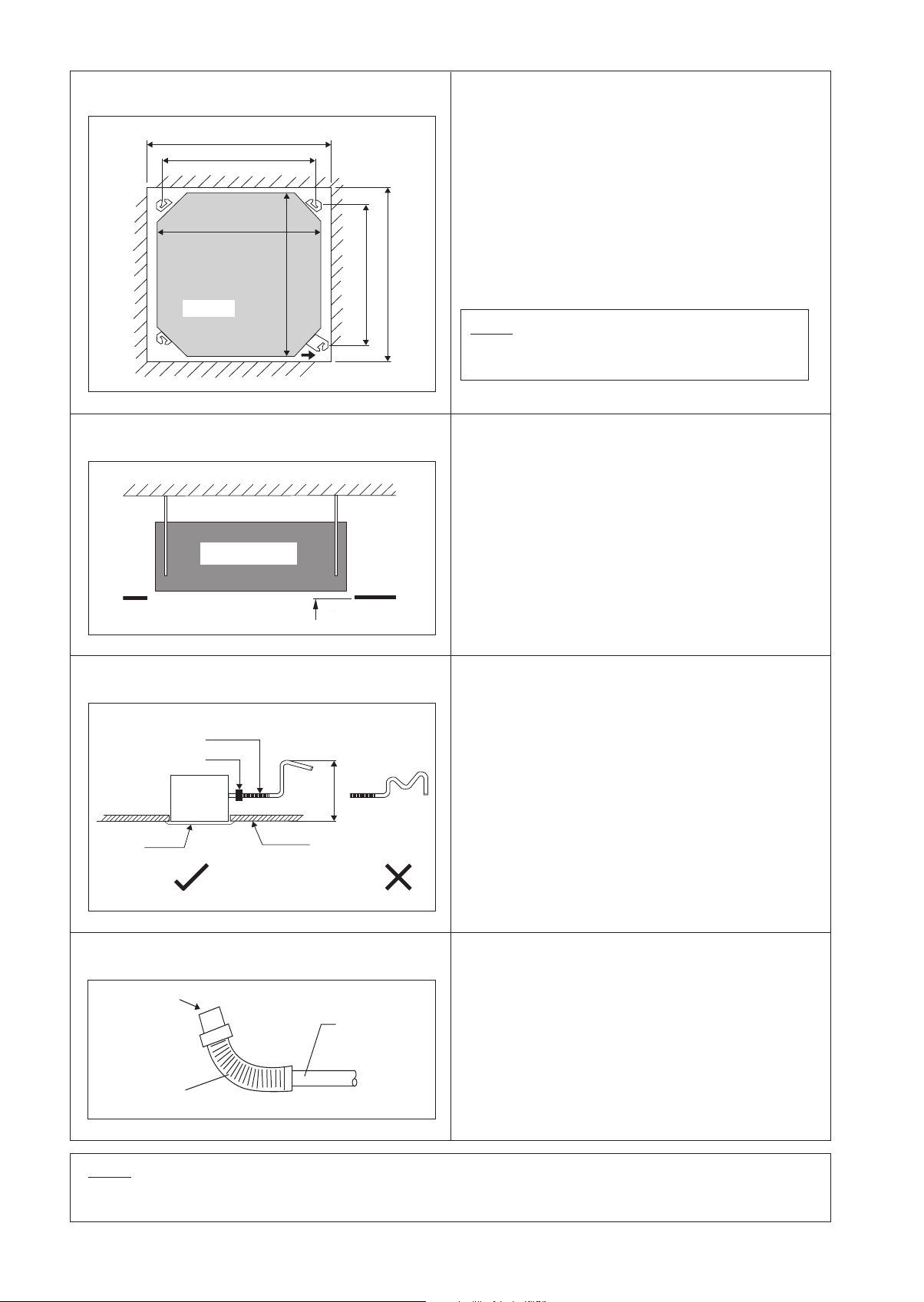
Unit Installation
Unit Hanging
Ceiling Opening Site = 890mm
Hanging Rod Site = 790mm
Unit size 820mm
Unit
Indoor Unit
Indoor Unit
Unit size 820mm
Hanging Rod Site = 621mm
Ceiling Opening Site = 890mm
Piping Direction
Ceiling
Ceiling
Board
Board
35mm
35.0 mm
• Measure and mark the position for the hanging rod.
Drill the hole for the angle nut on the ceiling and fix
the hanging rod.
• The installation template is extended according to
temperature and humidity. Check on dimensions in
use.
• The dimensions of the installation template are the
same as those of the ceiling opening dimensions.
• Before ceiling laminating work is covmpleted, be
sure to fit the installation template to the indoor unit.
NOTE
Be sure to discuss the ceiling drilling work with the
installers concerned.
• Confirm the pitch of the hanging rod.
• Hold the unit and hang it on the hanging rod with the
nut and washer.
• Adjust the unit height to 35mm between the indoor
unit bottom surface and the ceiling surface.
• Confirm with a level gauge that the unit is installed
horizontally and tighten the nut and bolt to prevent
unit failing and vibration.
• Open the ceiling board along the outer edge of the
paper installation template.
Drain Piping Work
Flexible Hose
Pipe Clamp
Indoor
Unit
Panel
Drain Test
Feed Water
Flexible Drain Hose
Ceiling
or less
700mm
Main Drain Pipe
• Drain pipe must be in downward gradient for smooth
drainage.
• Avoid installing the drain pipe in up and down slope
to prevent reversed water flow.
• During the drain pipe connection, be careful not to
exert extra force on the drain connector at indoor unit.
• The outside diameter of the drain connection at the
flexible drain hose is 20mm.
• Be sure to execute heat insulation (polyethylene foam
with thickness more than 8mm) on the drain piping to
avoid the condensed water dripping inside the room.
• Connect the main drain pipe to the flexible drain.
• Feed water from flexible drain hose to check the piping
for leakage.
• When the test is completed, connect the flexible drain
hose to the drain connector on the indoor unit.
NOTE
This Indoor Unit uses a drain pump for condensed water drainage. Install the unit horizontally to prevent water leakage
or condensation around the air outlet.
1-4
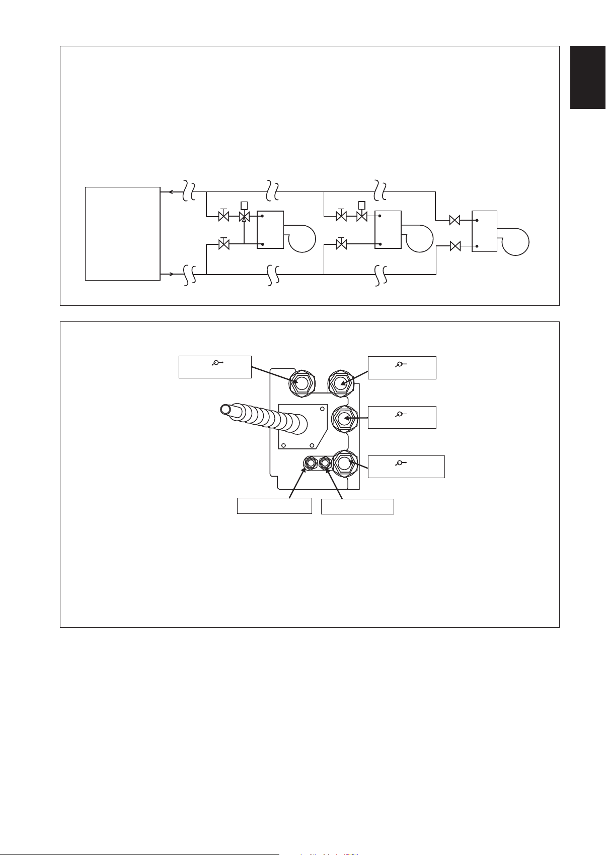
6. Water Piping Connection
• The indoor unit is equipped with water outlet and inlet connection. There is an air-vent that is fitted along with the
connection for air purging.
• 3 ways valve is required for cycling off or bypass the chilled water.
• Black steel pipe, polyethrene pipe and copper tube are recommended in the field installation. All types of piping and
connection must be insulated with polyethrene (ARMAFLEX type or equivalent) to avoid condensation.
• Do not used contaminated or damaged pipe and fitting for installation.
• Some main fitting components are needed in the system to enhance the capacity and ease the service, such as gate
valve, balancing valve, 2 ways or 3 ways valve, filter, strainer and etc.
English
Chiller
7. 4 Pipe system
Gate Valve
Gate Valve
Good Control Bad Control
WATER OUTLET 1
3 Way Valve
FCU
Gate Valve
Gate Valve
2 Way Valve
FCU
WATER INLET 1
WATER INLET 2
WATER OUTLET 2
Gate Valve
FCU
Gate Valve
Worst Control
ACCESS VALVE 1
ACCESS VALVE 2
Note :
• Water Inlet 1* must couple with Water Outlet 1 and Access Valve 1. (*1 connection to chiller)
• Water Inlet 2* must couple with Water Outlet 2 and Access Valve 2. (*2 connection to Boiler)
• Valve cap of Access Valve 1 is painted red for identification.
• All union joints are to be screwed in together with an “O” -ring. Apply Teflon white tape on the screw threads to ensure
leak proof joints.
• Secure all screw connection tightly to prevent leakage.
1-5
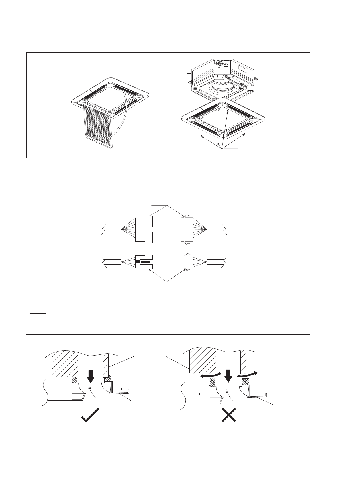
8. Panel Installation
• The front panel can only be fitted in one direction, follow the piping direction. (Follow piping arrow sticker on front panel)
• Be sure to remove the installation template before installing the front panel.
Open
Screw
• Open the air intake grille by pulling back the catchers and removing it together with filter from panel.
• Install the front frame panel onto the indoor unit by 4 screws and tighten it completely to prevent cool air leakage.
• Connect the LED wire and air swing wire to the indoor unit.
• The air swing connector must put inside the control box after connected.
LED Wire
From Front
Panel
Air Swing Wire
From Unit
Control Box
NOTE
Install the front frame panel firmly to prevent cool air leakage which will cause condensation and water dripping.
Indoor Unit
Cool
Air
Air Leak
Ceiling Board
Cool
Air
Air Leak
Ceiling Board
Panel
Panel
1-6
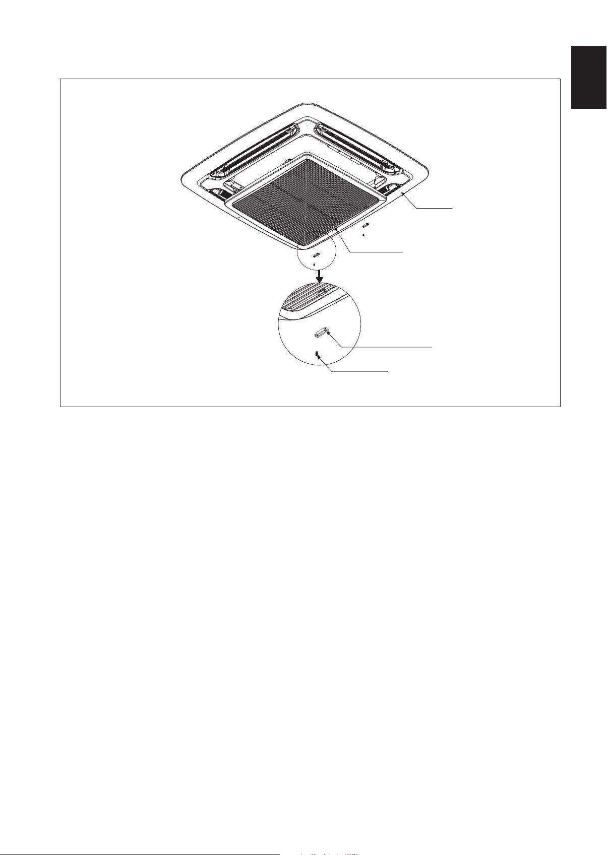
9. Cover Lock Grille (The moving part protection for user direct touching)
Cover lock grille must be installed as the figure below.
Intake Grille
Cover Lock Grille
(2pcs)
Screw M4 x 6
(2pcs)
English
Frame
If the unit need to be service, steps below shall be followed:
1. Confirm that the unit had been switched off before servicing the unit.
2. Use screwdriver to unlock the screw on the cover lock grille.
3. Remove the cover lock grille and open the intake grille for the service purpose.
4. Install the intake grille and screw the cover lock grille after service and make sure the unit is proper install.
1-7
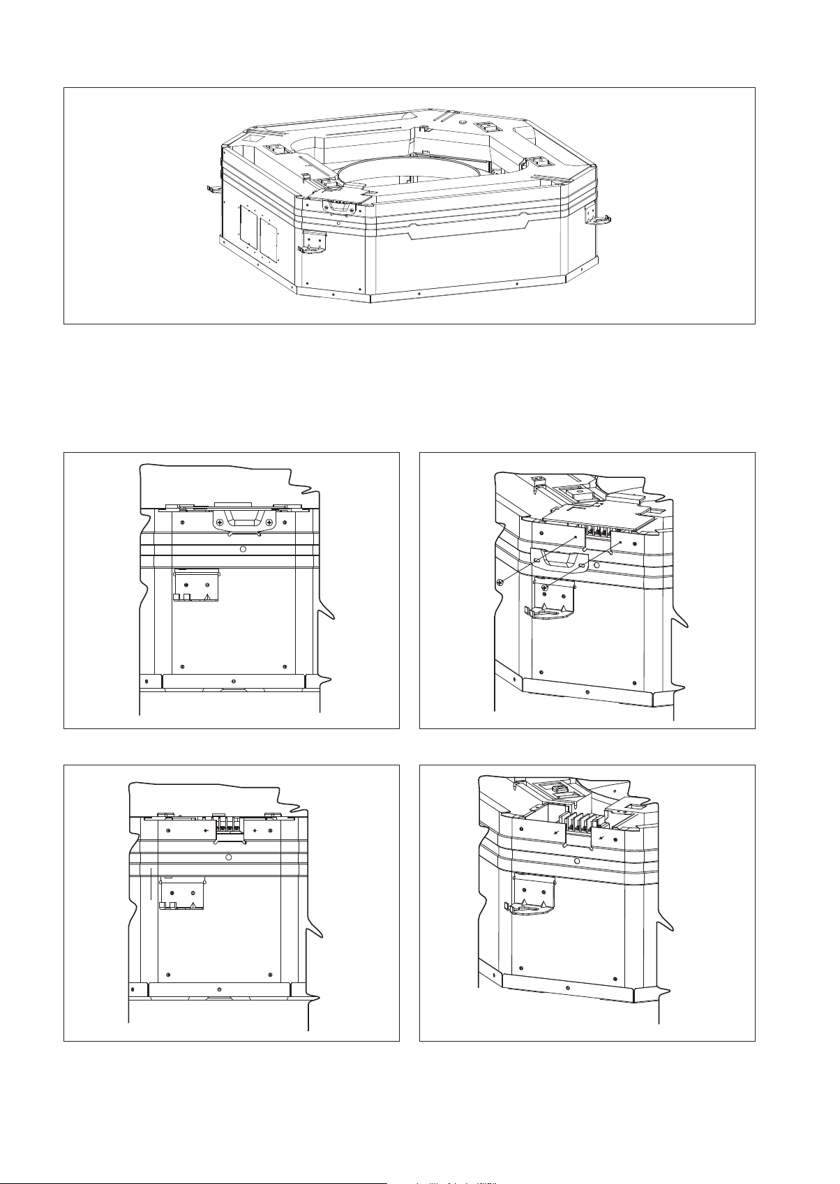
10. Wires Installation
Figure A
Figure A and Figure B shows the location of cover wire in indoor unit.
Steps to install power supply wires and wires from outdoor unit.
1. Remove wire cover by removing screws as shown in Figure C.
2. Wires will go through the hole as shown in Figure D and E respectively without crossing the height of the hole.
3. After that, wire cover will be assembled back to close the wire.
Figure B Figure C
Figure D Figure E
1-8
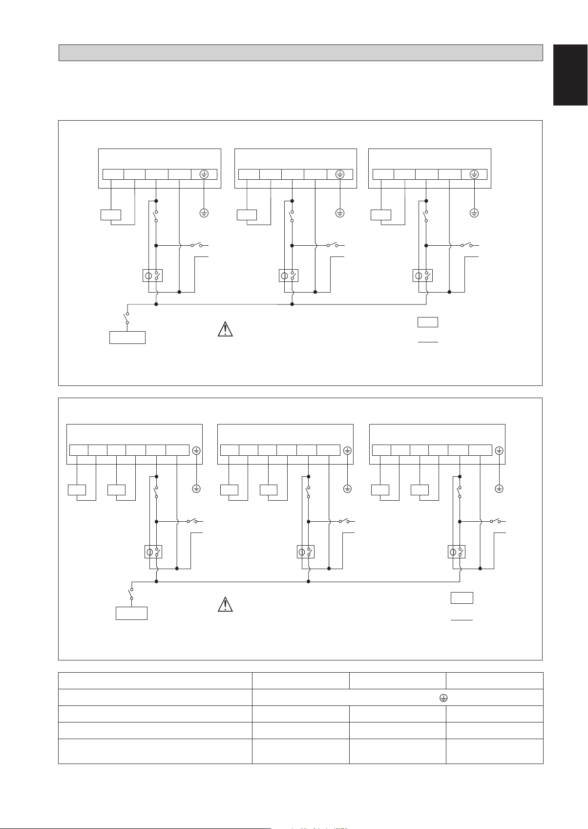
ELECTRICAL WIRING CONNECTION
IMPORTANT: * These values are for information only. They should be checked and selected to comply with local and/or
national codes and regulations. They are also subject to the type of installation and size of conductors.
** The appropriate voltage range should be checked with label data on the unit.
There must be an all pole disconnection in the supply mains with a contact separation of at least 3mm.
Model: FWG05/08/11AAT
English
FCU 1 FCU 2
LN1CVLV
X1
CHILLER
Model: FWG05/08/11AAF
FCU 1
HVLV
N1 CVLV N2 L N
NLN1CVLV N
3WV3WV
L
N
X2
There must be an all pole
disconnection in the supply
mains with a contact separation
of at least 3mm.
All power line must be from the
same phase.
FCU 2
HVLV N1 CVLV N2 L N
FCU 3
3WV
L
N
X1, X2,X3
HVLV N1 CVLV N2 L N
LN1CVLV N
X3
3 Way Valve
3WV
Relay
Field Supply Wire
FCU 3
L
N
3WV
3WV
L
N
X1
CHILLER
3WV3WV
X2
There must be an all pole
disconnection in the supply
mains with a contact separation
3WV3WV
L
N
X3
3 Way Valve
3WV
X1, X2,X3
Relay
Field Supply Wire
L
N
of at least 3mm.
All power line must be from the
same phase.
Model FWG05AAT(F) FWG08AAT(F) FWG11AAT(F)
Voltage Range**
Recommended time delay fuse* (A)
Power Supply Cable* (mm2)
Interconnection cable size* (mm2)
Number of conductors
220V-240V/~/50Hz +
222
1.5 1.5 1.5
333
1-9
• All wires must be firmly connected.
• Make sure all the wire not touching the refrigerant piping, compressor or any moving parts of the fan motor.
• The connecting wire between the indoor unit and the outdoor unit must be clamped on the wire clamps.
• The power supply cord must be equivalent to H07RN-F which is the minimum requirement.
• When attaching the terminal box lid, make sure do not pinch any wires.
• After all the wiring connections are done, fill in any gaps/holes with insulation (procured locally) to prevent small animals
and insects entering the unit from outside.
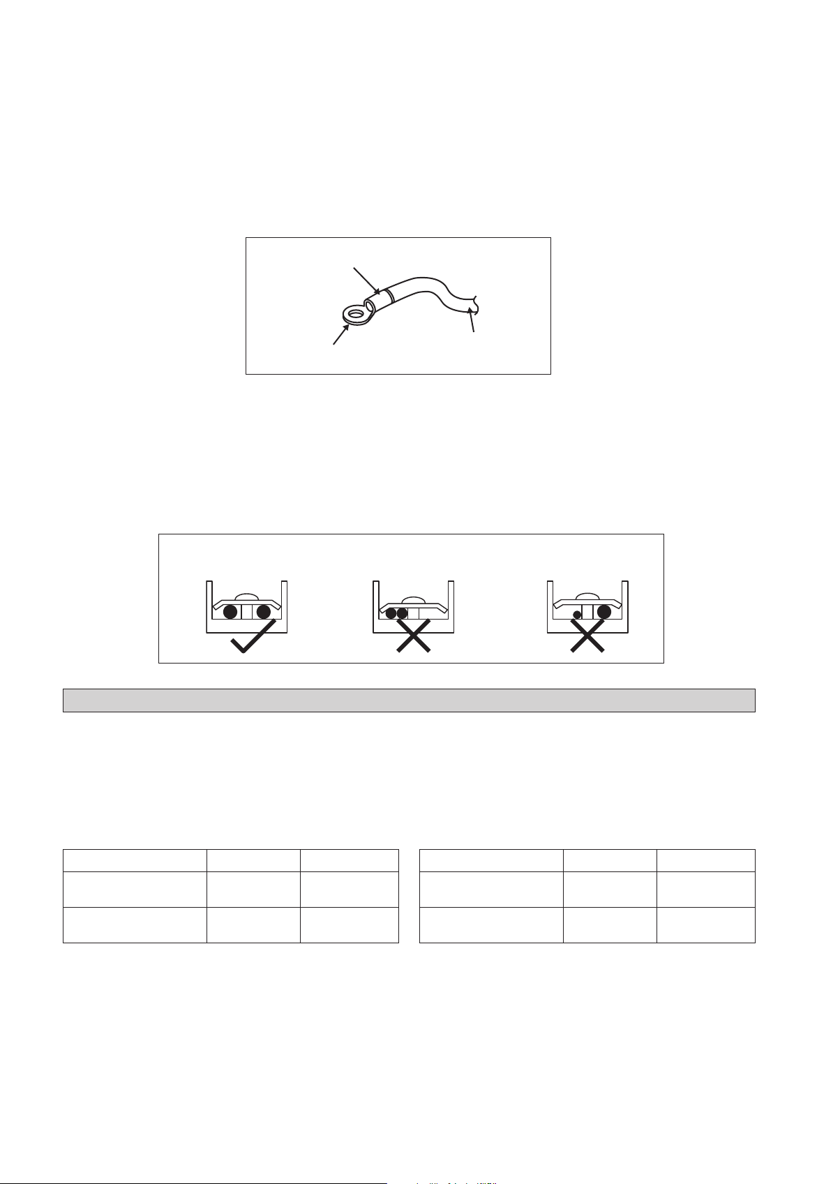
• Use round crimp-style terminal for connecting wires to the power supply terminal block. Connect the wires by matching
to the indication on terminal block. (Refer to the wiring diagram attached on the unit).
Attach insulation sleeve
Round crimp-style terminal
Electric wire
Step to connect the installation wire:
• Used the correct screwdriver for tightening the terminal screws. If the block is too small, the mad of the screw might be
damaged and the screw will not be properly tightened. If tightening too hard, screw might be damaged.
• Do not connect wire at different gauge to the same proper supply terminal.
• Use specified electric wire. Connect the wire securely to the terminal. Lock the wire down without applying excessive
force to the terminal.
• Keep wiring in mat order and not to obstruct other equipment such as popping open the terminal box lid.
Connect wires of the
same gauge to both side.
Do not connect wires of the
same gauge to one side.
Do not connect wires
of different gauges.
OPERATING RANGE
Operating Limits:
Thermal carrier : Water
Water temperature : 4°C ~ 10°C (Cooling), 35°C ~ 50°C (2 Pipes), 35°C ~ 70°C (4 Pipes),
Maximum water pressure : 16 bar
Air temperature : (as below)
Cooling Unit Heating Unit
Temperature Ts °C/°F Th °C/°F
Minimum indoor
temperature
Maximum indoor
temperature
16.0 / 60.8 11.0 / 51.8
32.0 / 89.6 23.0 / 73.4
Temperature Ts °C/°F Th °C/°F
Minimum indoor
temperature
Maximum indoor
temperature
Ts: Dry bulb temperature. Th: Wet bulb temperature.
1-10
16.0 / 60.8 -
30.0 / 86.0 -
 Loading...