

Daikin FTKC09NV2S, FTKC12NV2S, ATX20J2V1B, ATKC12RV2S, ATX25J2V1B Service Manual
...
REMOVAL
PROCEDURE
SERVICE MANUAL
Indoor Unit
Inverter
Wall Mounted Type
1.5/2.0/2.5/3.0/3.5 kW Class
9000/12000 Btu/h Class
Si041264EC

Service Manual
Removal Procedure
Indoor Unit
zCooling Only zHeat Pump
ATKC09RV2S ATX20J2V1B
ATKC12RV2S ATX25J2V1B
ATX35J2V1B
FTKC09NV2S
FTKC12NV2S FTX20J2V1B
FTX25J2V1B
FTKC25NVM FTX35J2V1B
FTKC35NVM
FTXM20HVMV
FTKC15NVM4 FTXM25HVMV
FTKC20NVM4 FTXM35HVMV
FTKC25NVM4
FTKC35NVM4 FTXP20HVLT
FTXP25HVLT
FTKC25NVMM FTXP30HVLT
FTKC35NVMM
FTKC25NVMV
FTKC35NVMV
FTKC09PV2S
FTKC12PV2S
FTKC15PVM
FTKC20PVM
FTKC25PVM
FTKC35PVM
FTKC15PVM4
FTKC20PVM4
FTKC25PVM4
FTKC35PVM4
FTKC25PVMM
FTKC35PVMM
FTKC20PVMV
FTKC25PVMV
FTKC35PVMV

Si041264EC
Removal Procedure 1
Table of Contents
1. Air Filters .................................................................................................2
2. Horizontal Blade......................................................................................3
3. Front Panel..............................................................................................4
4. Front Grille ..............................................................................................5
5. Electrical Box / Vertical Blades ...............................................................6
6. Swing Motor / PCBs................................................................................9
7. Indoor Heat Exchanger .........................................................................12
8. Fan Rotor / Fan Motor...........................................................................15
Note:
The illustrations may be slightly different depending on the model.
Air Filters Si041264EC
2 Removal Procedure
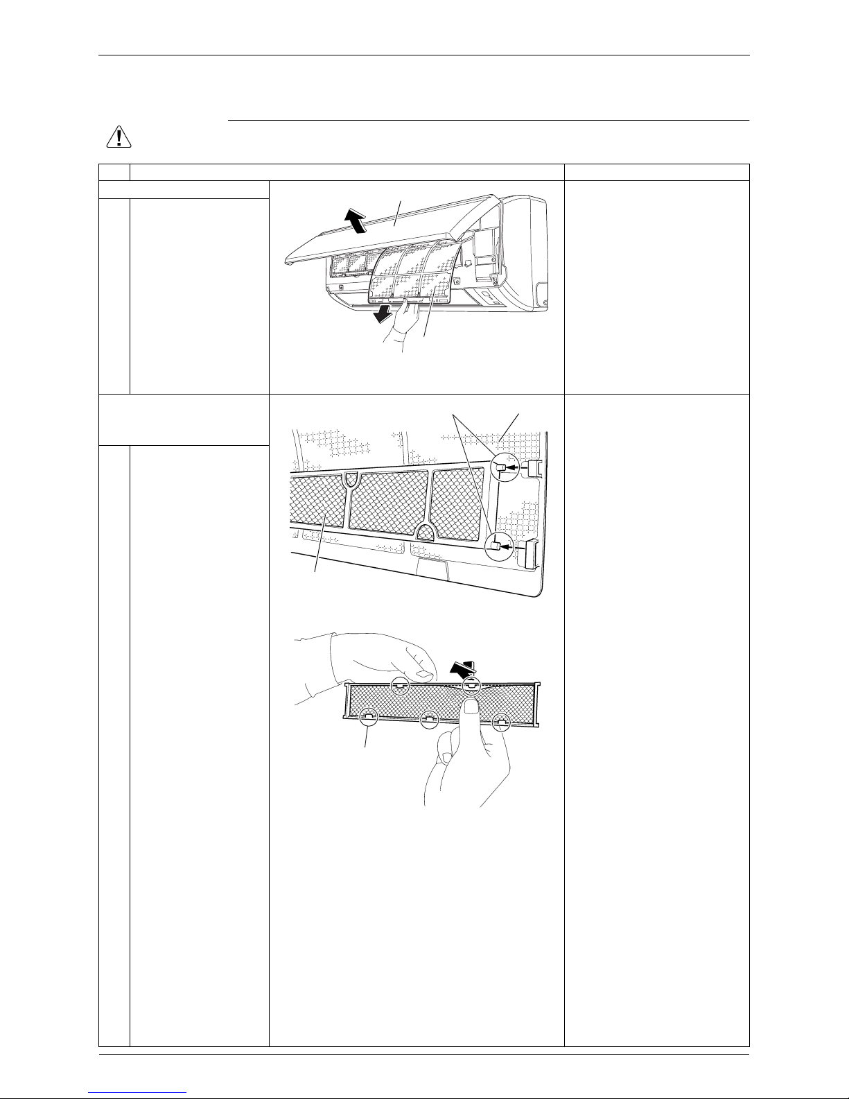
1. Air Filters
Warning
Be sure to wait for 10 minutes or more after turning off all power supplies before
disassembling work.
Step Procedure Points
1. Remove the air filters.
The air filter is not marked
for difference between the
right and left sides.
When reassembling, insert
the air filter along the guides.
Insert the air filter with the
“FRONT” mark faced up.
Be sure to fit the 2 bottom
hooks when installing the air
filter.
12Open the front panel.
Pull out the air filter
downward and remove
it.
2. Remove the Titanium
apatite photocatalytic
air-purifying filters.
1 Remove the Titanium
apatite photocatalytic
air-purifying filter ASSY
by unfastening the 2
projections from the
back of the air filter.
2 Unfasten the 5 hooks
and remove the
Titanium apatite
photocatalytic airpurifying filter from its
frame.
To prevent damage, do not
remove the Titanium apatite
photocatalytic air-purifying
filter from the frame when
cleaning it.
The Titanium apatite
photocatalytic air-purifying
filter is not marked for
difference between the right
and left sides.
(R18236)
Air filter
Front panel
Projection
Air filter
Titanium apatite
photocatalytic
air-purifying filter ASSY
(R20666)
Hook
(R8027)
Si041264EC Horizontal Blade
Removal Procedure 3
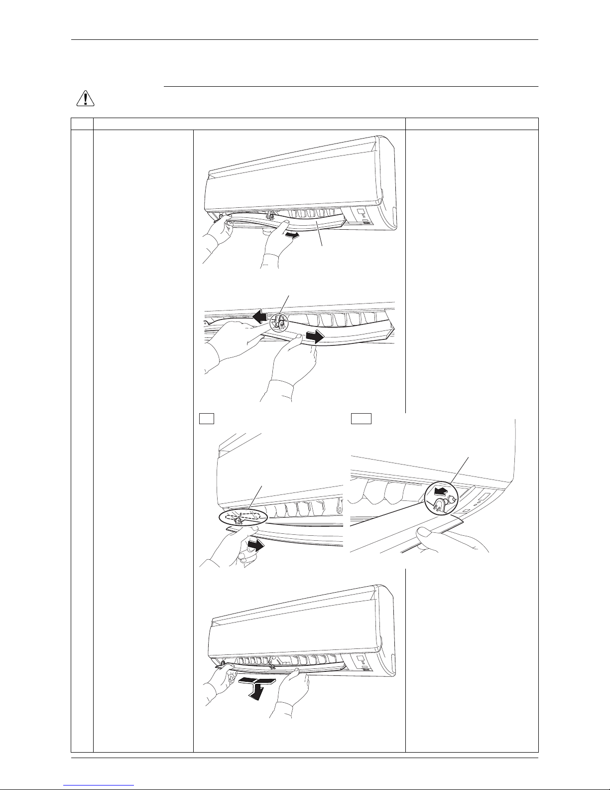
2. Horizontal Blade
Warning
Be sure to wait for 10 minutes or more after turning off all power supplies before
disassembling work.
Step Procedure Points
1 Release the center
shaft while bending the
horizontal blade
slightly.
Installation procedure
1. Fit the right shaft of the
horizontal blade first. Make
sure to rotate the horizontal
blade so the shaft fits in the
correct position.
2. Fit the horizontal blade to the
center and left shafts.
23Release the left shaft.
Release the right shaft.
4 Remove the horizontal
blade.
(R18188)
Horizontal blade
(R23355)
Shaft
(R23349)
Shaft
Left
Right
Shaft
(R17333)

Front Panel Si041264EC
4 Removal Procedure
3. Front Panel
Warning
Be sure to wait for 10 minutes or more after turning off all power supplies before
disassembling work.
Step Procedure Points
1 Open the front panel.
2 Release the right rotary
shaft.
The rotary shaft on each
side can be released by
sliding each shaft inward.
3 Release the left rotary
shaft and remove the
front panel.
When reassembling the front
panel, fit the right and left
rotary shafts one by one into
the grooves and fully push
them in position.
Left side
Front panel
Right side
(R11627)
Right
Rotary shaft
(R11628)
Left
Rotary shaft
(R11629)
 Loading...