

Daikin FTXG25EV1BW, FTXG35EV1BS, ATXG35EV1B, FTXG35EV1BW, FTXG25EV1BS Service Manual
...
REMOVAL
PROCEDURE
SERVICE MANUAL
Indoor Unit
Inverter
Wall Mounted Type
2.5/3.5 kW Class
Si04-858

Service Manual
Removal Procedure
Indoor Unit
zHeat Pump
ATXG25EV1B
ATXG35EV1B
FTXG25EV1BW
FTXG35EV1BW
FTXG25EV1BS
FTXG35EV1BS
FTXG25EVMAW
FTXG35EVMAW
FTXG25EVMAS
FTXG35EVMAS
FTXG25FVMAW
FTXG35FVMAW
FTXG25FVMAS
FTXG35FVMAS

Si04-858
Removal Procedure 1
Table of Contents
1. Removal of Air Filter................................................................................2
2. Removal of Front Grille ...........................................................................4
3. Removal of Assembly of Front Panel Mechanism ................................10
4. Removal of Lamp Cover .......................................................................13
5. Removal of Horizontal Blade.................................................................14
6. Removal of Reduction Motor.................................................................16
7. Removal of Outlet Grille........................................................................19
8. Removal of Vertical Blades and Swing Motor .......................................20
9. Removal of Electrical Box .....................................................................24
10.Removal of PCB....................................................................................30
11.Removal of Heat Exchanger .................................................................36
12.Removal of Fan Rotor and Fan Motor...................................................39
Note:
The illustrations may be slightly different depending on the model.
Removal of Air Filter Si04-858
2 Removal Procedure
1. Removal of Air Filter
Procedure Warning Be sure to wait 10 minutes or more after turning off all power supplies
before disassembling work.
Step
Procedure Points
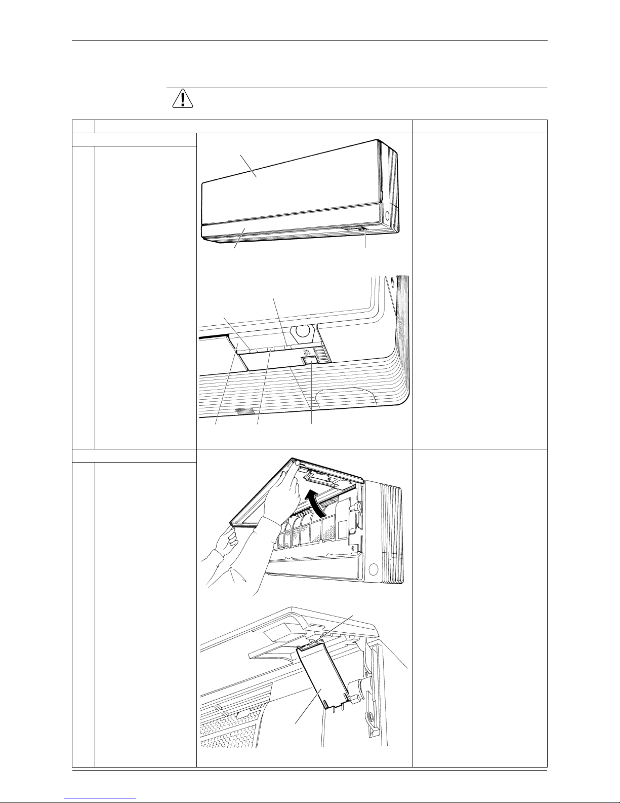
1. Features
When the signal receiver
catches a signal from the
remote controller, it
produces beep sound and
the operation lamp blinks.
2. Remove the air filters.
1
Hold the front panel by
the tabs on the both
sides and lift it until it
stops with a click.
2
Keep the front panel
open with the support
plate.
Front panel (top)
Slot-in panel Room temperature sensor
(R5001)
Intelligent
eye lamp
Signal
receiver
Timer lamp
ON/OFF switch
Operation lamp
(R5002)
(R5003)
Support point
Support plate
(R5004)
Si04-858 Removal of Air Filter
Removal Procedure 3
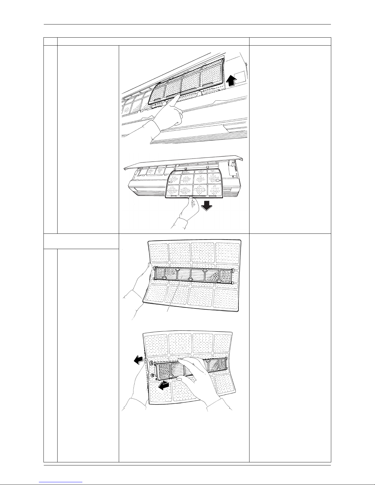
3
Lift an air filter upwards
slightly and then pull it
out downwards.
The right and left air filters
are interchangeable.
Insert the air filters along
grooves when installing.
When installing, insert 2
hooks of the air filter
completely.
3. Remove the air-purifying
filter.
The right and left airpurifying filters are
interchangeable.
1
Titanium Apatite Photocatalytic Air-purifying
Filter is fixed on the rear
of the air filter.
2
Bend the air filter to
release the protrusions
and remove the
Titanium Apatite
Photocatalytic AirPurifying filter.
Step
Procedure Points
(R5005)
(R5006)
Titanium Apatite Photocatalytic
Air-purifying Filter
(R3763)
(R3764)

Removal of Front Grille Si04-858
4 Removal Procedure
2. Removal of Front Grille
Procedure Warning Be sure to wait 10 minutes or more after turning off all power supplies
before disassembling work.
Step
Procedure Points
1. Remove the front panel.
Start the removal procedure
of front grille when the
panels are closed.
Slide the front panel side to
side to release each axis.
When assembling, align the
right and left axes with
grooves in turn and insert
them to the end.
1
Open the front panel to
the horizontal position.
Release the both sides
pivots and remove the
front panel.
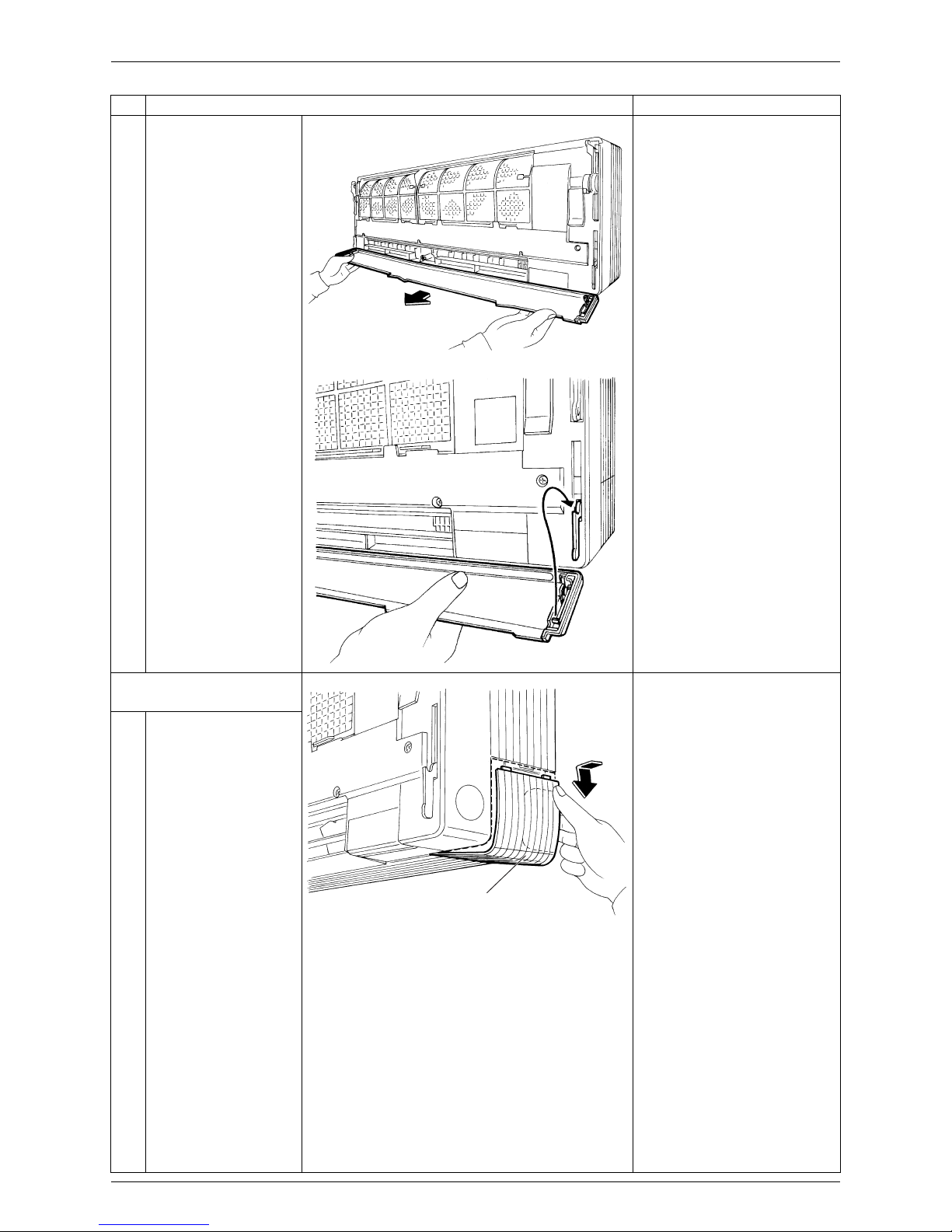
2. Remove the slot-in panel.
1
Pull the lower side of
the panel.
2
Lift the panel and
remove from the slots.
(R5007)
(R5008)
Slot-in panel
(R5009)
(R5010)
Si04-858 Removal of Front Grille
Removal Procedure 5
3
The slot-in panel is
fixed only at the both
ends.
4
When assembling, fit
the axes of the slot-in
panel from above.
Push the lower part of
the slot-in panel and
attach to the running
gear.
3. Remove the service
cover.
The service cover has no
screw.
Hooks can be caught from
either right side or lower
side.
1
Bend the service cover
inside and release the
hooks.
Step
Procedure Points
(R5011)
(R5012)
Service cover
(R5013)
Removal of Front Grille Si04-858
6 Removal Procedure
2
The service cover has 2
hooks on the right side
and 4 hooks on the
lower side.
When assembling, fit the
right side hooks and insert
the lower hooks while
bending the service cover.
3
Loosen the screw on
the service cover of
electrical box.
Step
Procedure Points
Hooks
Hooks
(R5014)
(R5016)
Service cover of
electrical box
(R3778)
Si04-858 Removal of Front Grille
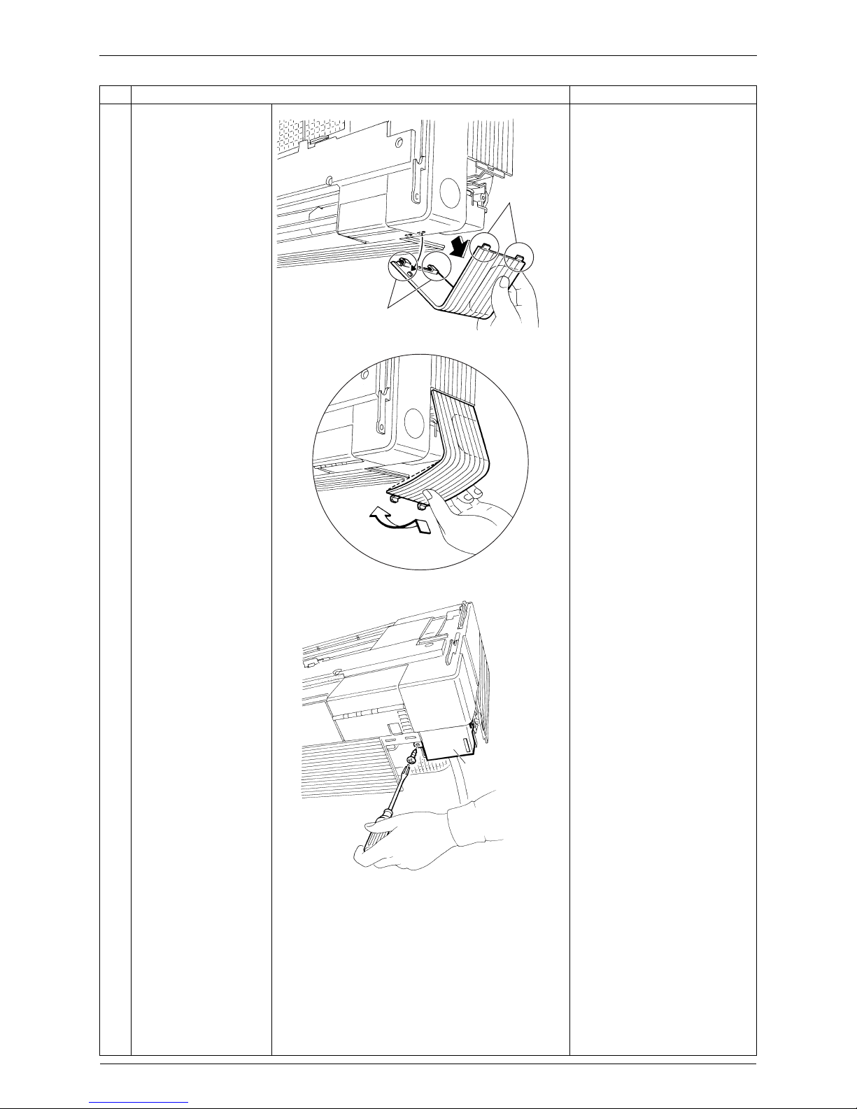
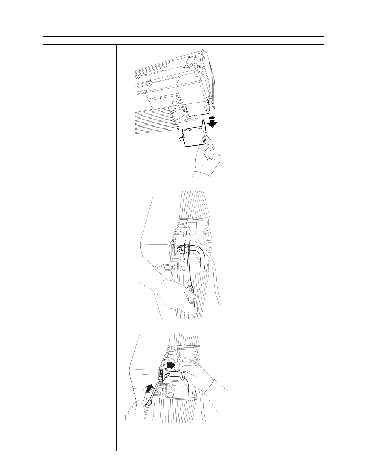
Removal Procedure 7
4
Pull down and remove
the service cover of
electrical box.
5
Loosen the screw on
the fixing plate.
6
Push the white section
on the terminal board
and release the relay
wires.
Step
Procedure Points
(R3779)
(R3780)
(R3781)
Removal of Front Grille Si04-858
8 Removal Procedure
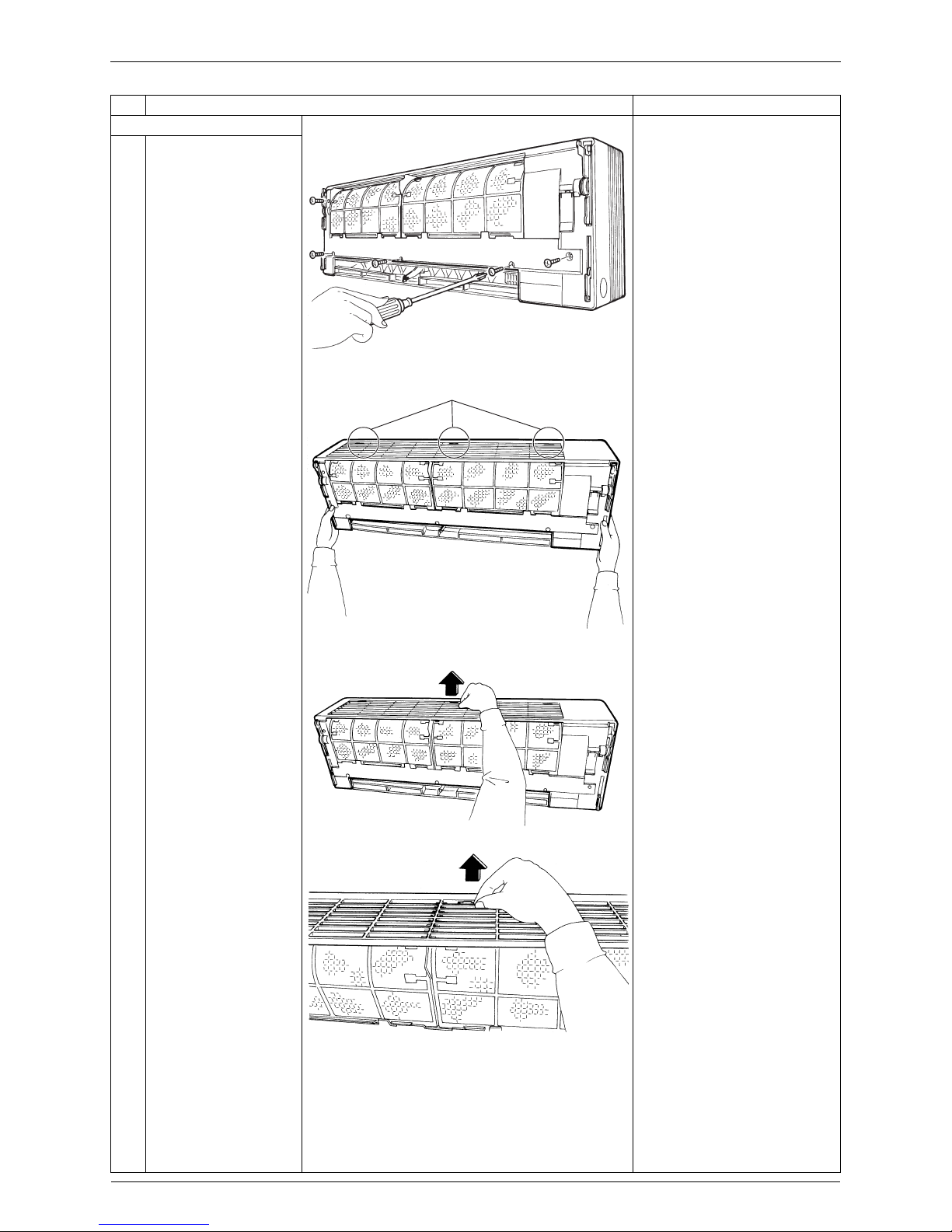
4. Remove the front grille.
The front grille has no screw
inside flaps.
1
Loosen the 5 screws.
2
The front grille has 3
hooks on the upper
side.
3
Lift the upper part of the
front grille and release
the hooks.
Release the center
hook first.
Be careful not to cut your
finger by the fins of the heat
exchanger.
As for the horizontal blades,
fully opened position is easy
to reassemble and remove.
Step
Procedure Points
(R5017)
Hooks
(R5018)
(R5019)
(R5020)
Si04-858 Removal of Front Grille
Removal Procedure 9
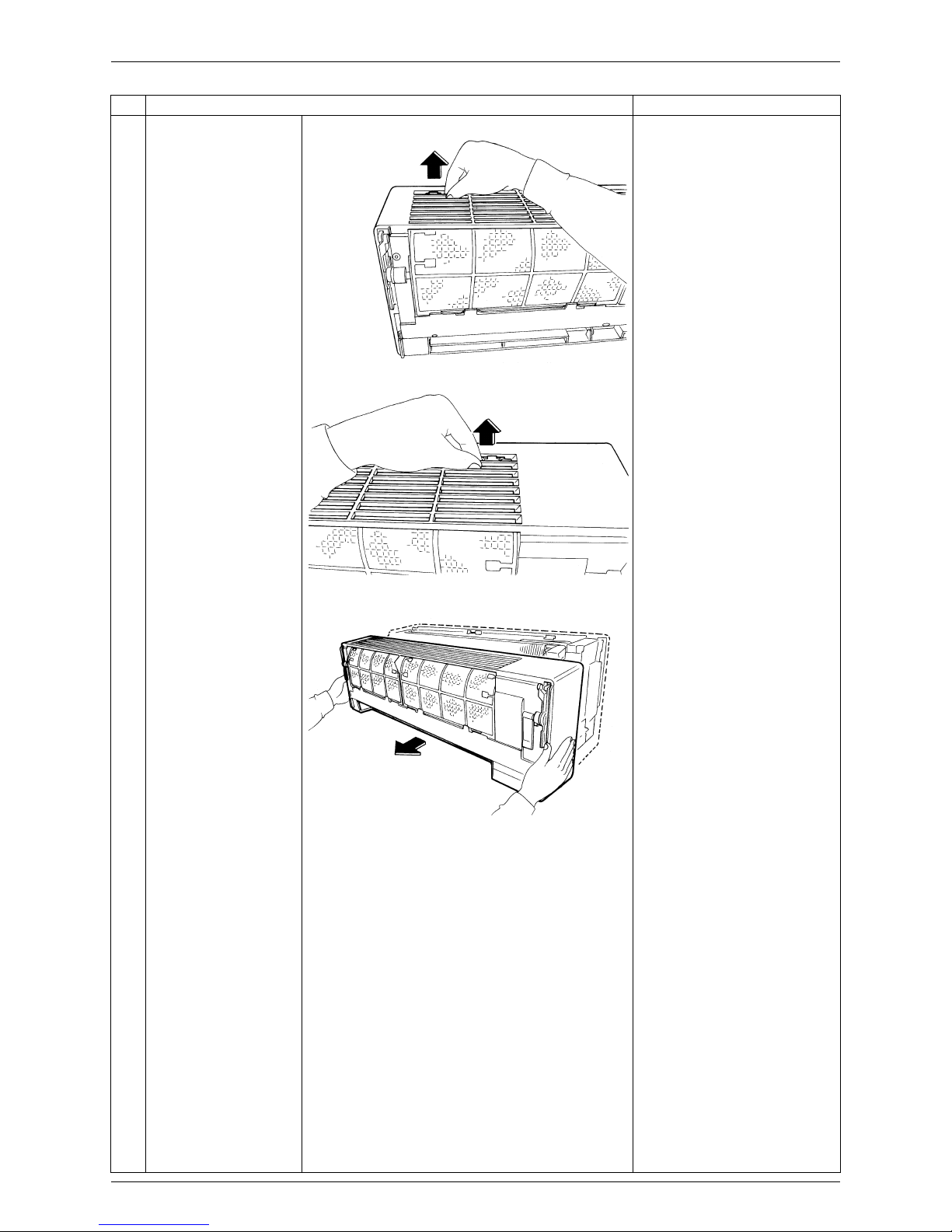
4
Release the both sides
hooks.
5
Pull the front grille out
horizontally and remove
it.
When assembling, install the
front grille horizontally so as
not to stuff the flap inside.
When assembling, make
sure the three hooks are
caught properly.
Step
Procedure Points
(R5021)
(R5073)
(R5022)
Removal of Assembly of Front Panel Mechanism Si04-858
10 Removal Procedure
3. Removal of Assembly of Front Panel Mechanism
Procedure Warning Be sure to wait 10 minutes or more after turning off all power supplies
before disassembling work.
Step
Procedure Points
Remove the front grille.
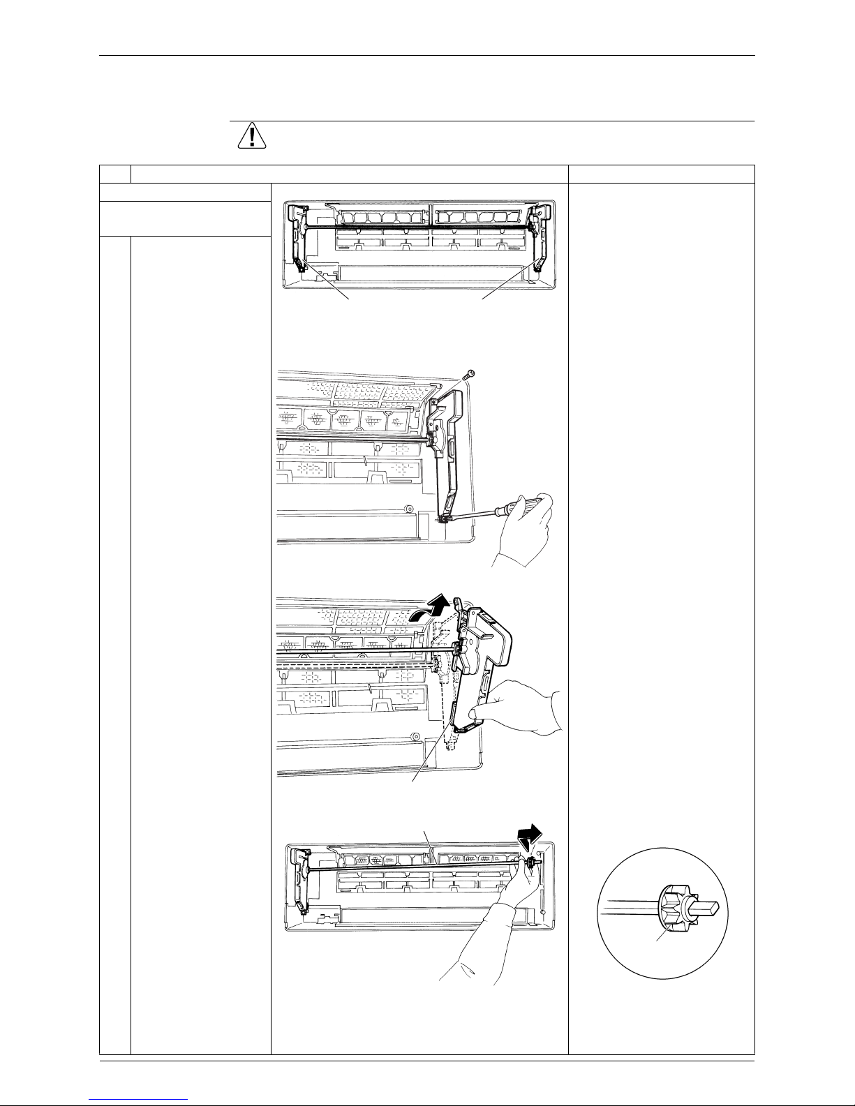
1. Remove the assembly of
front panel mechanism.
1
The back of the front
grilles
2
Loosen the 2 screws of
the assembly (left).
3
Remove the assembly.
When assembling, insert the
lower rack plate first.
4
Lift the shaft and pull it
out to the rightward.
Be careful so as not to lose
the drive gear.
(R5023)
Assy. of front panel
mechanism (right)
Assy. of front panel
mechanism (left)
(R5024)
Lower rack plate
(R5025)
Shaft
(R5026)
Drive gear
(R3794)
Si04-858 Removal of Assembly of Front Panel Mechanism
Removal Procedure 11
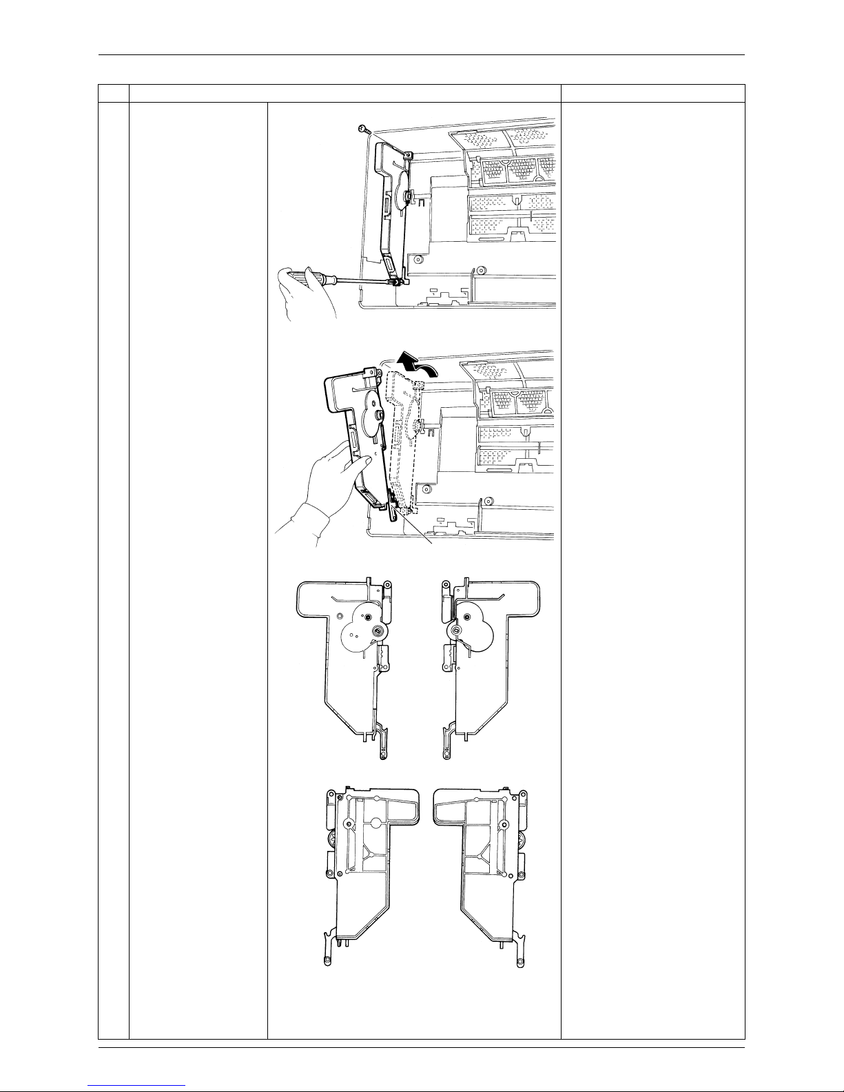
5
Loosen the 2 screws of
the assembly (right).
6
Remove the assembly.
When assembling, insert the
lower rack plate first.
Step
Procedure Points
(R5027)
Lower rack plate
(R5028)
(R5029)
(R5030)

Removal of Assembly of Front Panel Mechanism Si04-858
12 Removal Procedure
2. Remove the lower rack
plate.
1
Loosen the 3 screws of
the left assembly cover.
2
Hold the assembly
horizontally and release
the upper hook.
When you demand small
parts like cogs and rollers,
order a set of assembly.
3
Keep the assembly
horizontally and undo
the hooks on side and
lower sides.
4
Remove the running
gear.
Be careful so as not to lose
the rollers and the cogs.
When you demand small
parts like cogs and rollers,
order a set of assembly.
Step
Procedure Points
(R5031)
Hook
(R5032)
Hooks
(R5033)
Running gear
Lower rack plate
(R5034)
 Loading...