

Daikin EWWD340DZXEA1, EWWH320DZXSA1, EWWH230DZXSA1, EWWH245DZXEA1, EWWD470DZXEA1 Installation, Operation, Maintenance Manual
...
D-EIMWC01405-18EN- 1/32
REV
01
Date
July 2018
Supersedes
D–EIMWC01405-18EN
WATER COOLED OIL FREE CENTRIFUGAL CHILLERS
EWWD – DZ
EWWH - DZ
Cooling capacity from 320 to 1480 kW
50Hz - Refrigerant: HFC R134a, R1234ze(E)
Original Instructions
Installation, maintenance and operating manual
D–EIMWC01405-18_01EN

D-EIMWC01405-18EN- 2/32
Contents
1 INTRODUCTION ...................................................................................................................................................................... 6
1.1 General Description .................................................................................................................................................................. 6
1.2 Application ................................................................................................................................................................................ 6
1.3 Information about R1234ze(E) .................................................................................................................................................. 6
1.4 Installation Safety ..................................................................................................................................................................... 7
1.4.1 Additional guidelines for safe use of R1234ze(E) for equipment located in the open air ............................................ 7
1.4.2 Additional guidelines for safe use of R1234ze(E) for equipment located in a machinery room................................... 7
2 INSTALLATION ....................................................................................................................................................................... 9
2.1 Storage ..................................................................................................................................................................................... 9
2.2 Receiving and handling ............................................................................................................................................................ 9
2.3 Lifting instructions ................................................................................................................................................................... 10
2.4 Positioning and assembly ....................................................................................................................................................... 11
2.5 Shock absorbers ..................................................................................................................................................................... 11
2.6 Anchoring ............................................................................................................................................................................... 12
2.7 Water pipes ............................................................................................................................................................................ 12
2.7.1 Evaporator and condenser water pipes ................................................................................................................... 12
2.7.2 Flow Switch ............................................................................................................................................................ 12
2.8 Water treatment ...................................................................................................................................................................... 13
2.9 Temperature limits and water flow .......................................................................................................................................... 14
2.10 Minimum water content in the system ..................................................................................................................................... 14
2.11 Evaporator frost protection...................................................................................................................................................... 15
2.12 Condenser protection and design considerations .................................................................................................................... 15
2.12.1 Condensation control with evaporative cooling tower ......................................................................................... 15
2.12.2 Condensation control with well water ................................................................................................................. 16
2.13 Chilled water control sensor .................................................................................................................................................... 16
2.14 Safety Valve ........................................................................................................................................................................... 17
2.15 Open the isolation and/or shut off valves ................................................................................................................................ 17
2.16 Electrical connections ................................ ................................................................................................ ............................. 17
2.17 Phase imbalance .................................................................................................................................................................... 17
2.18 Control circuit ......................................................................................................................................................................... 17
3 OPERATION .......................................................................................................................................................................... 19
3.1 Operator’s responsibilities....................................................................................................................................................... 19
3.2 Unit description ....................................................................................................................................................................... 19
3.3 Safeties for each cooling compressor ..................................................................................................................................... 20
3.4 System safeties ...................................................................................................................................................................... 20
3.5 Regulation type....................................................................................................................................................................... 20
3.6 Compressor Lead-Lag ............................................................................................................................................................ 20
3.7 High condensing pressure control ........................................................................................................................................... 20
4 MAINTENANCE ..................................................................................................................................................................... 21
4.1 Pressure/Temperature Table .................................................................................................................................................. 22
4.2 Routine maintenance .............................................................................................................................................................. 23
4.2.1 Check condenser performance ............................................................................................................................... 23
4.2.2 Electronic expansion valve ...................................................................................................................................... 23
4.2.3 Cooling circuit ......................................................................................................................................................... 23
4.2.4 Refrigerant charge .................................................................................................................................................. 26
4.2.5 Check the refrigerant charge ................................................................................................................................... 26
4.2.6 Electrical Installation ............................................................................................................................................... 26
4.3 Cleaning and Storage ................................ ................................................................................................ ............................. 27
4.4 Seasonal maintenance ........................................................................................................................................................... 27
4.4.1 Seasonal shutdown ................................................................................................................................................ 27
4.4.2 Seasonal start up .................................................................................................................................................... 27
5 SERVICE SCHEDULE ........................................................................................................................................................... 27
6 MAINTENANCE SCHEDULE ................................................................................................................................................. 28
7 CHECKS BEFORE FIRST START UP ................................................................................................................................... 29
8 IMPORTANT INFORMATION ON USED REFRIGERANT ..................................................................................................... 30
8.1 Factory and Field charged units instructions ........................................................................................................................... 30
9 PERIODIC CHECKS AND COMMISSIONING OF PRESSURE VESSELS ............................................................................ 31
10 DEMOLITION AND DISPOSAL ............................................................................................................................................. 31
11 DURATION ............................................................................................................................................................................ 31
List of Figures
Fig. 1 - Single compressor unit component descriptions ........................................................................................................................... 3
Fig. 2 - Dual compressor unit component descriptions .............................................................................................................................. 4
Fig. 3-Description of the labels applied to the electric panel ...................................................................................................................... 5
Fig. 4 - Unit positioning ........................................................................................................................................................................... 11
Fig. 5-Water quality ................................................................................................................................................................................ 13
Fig. 6 – Electrical Panel Layout .............................................................................................................................................................. 20
Fig. 7-P&ID Mono and Dual compressor ................................................................................................................................................ 24
Fig. 8-P&ID Mono and Dual compressor with economizer ...................................................................................................................... 25
D-EIMWC01405-18EN- 3/32
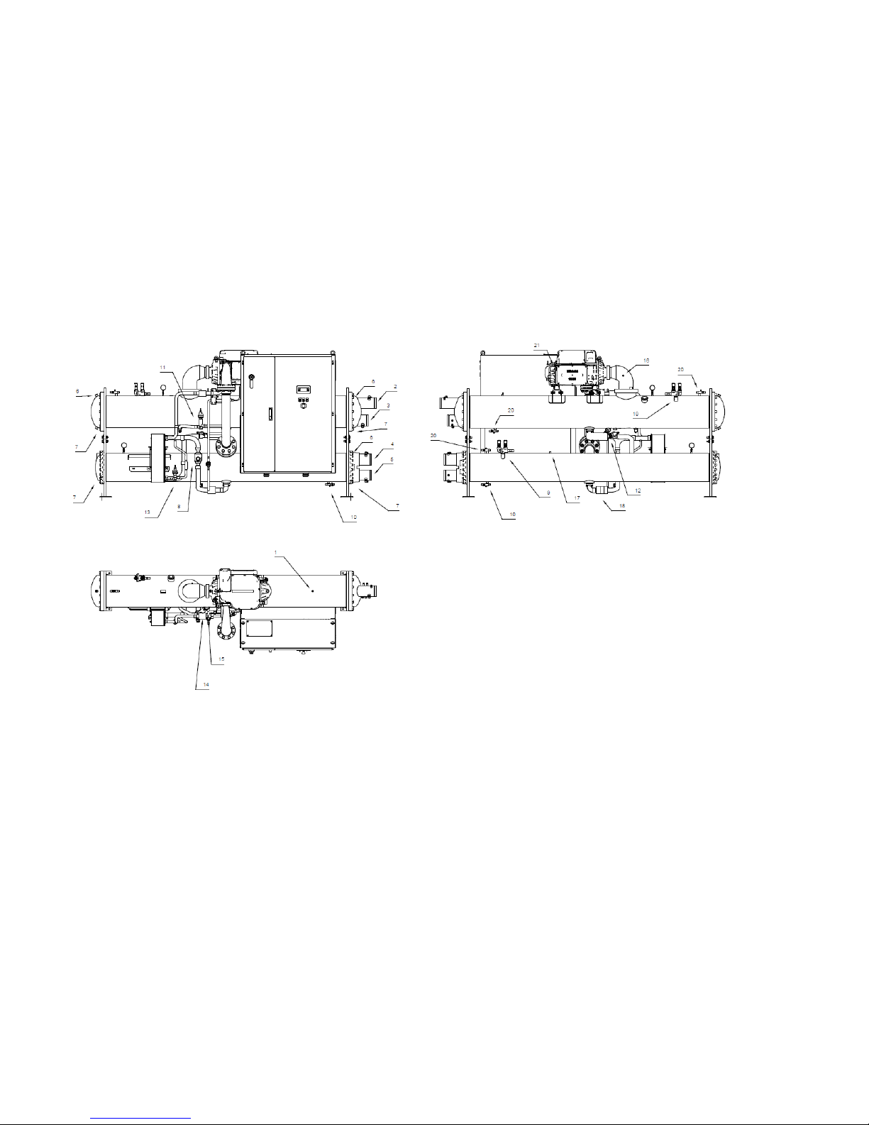
Fig. 1 - Single compressor unit component descriptions
D-EIMWC01405-18EN- 4/32
1 2 3 4 5 6 7 8 9
10
11
Low pressure
transducer
Evaporator outlet
water temperature
sensor
Evaporator inlet
water temperature
sensor
Condenser outlet
water temperature
sensor
Condenser inlet
water temperature
sensor
Air purge
Water drain
Liquid line
shut-off valve
High
pressure
safety valves
Refrigerant
charge service
valve
Starter
valve
12
13
14
15
16
17
18
19
20
21
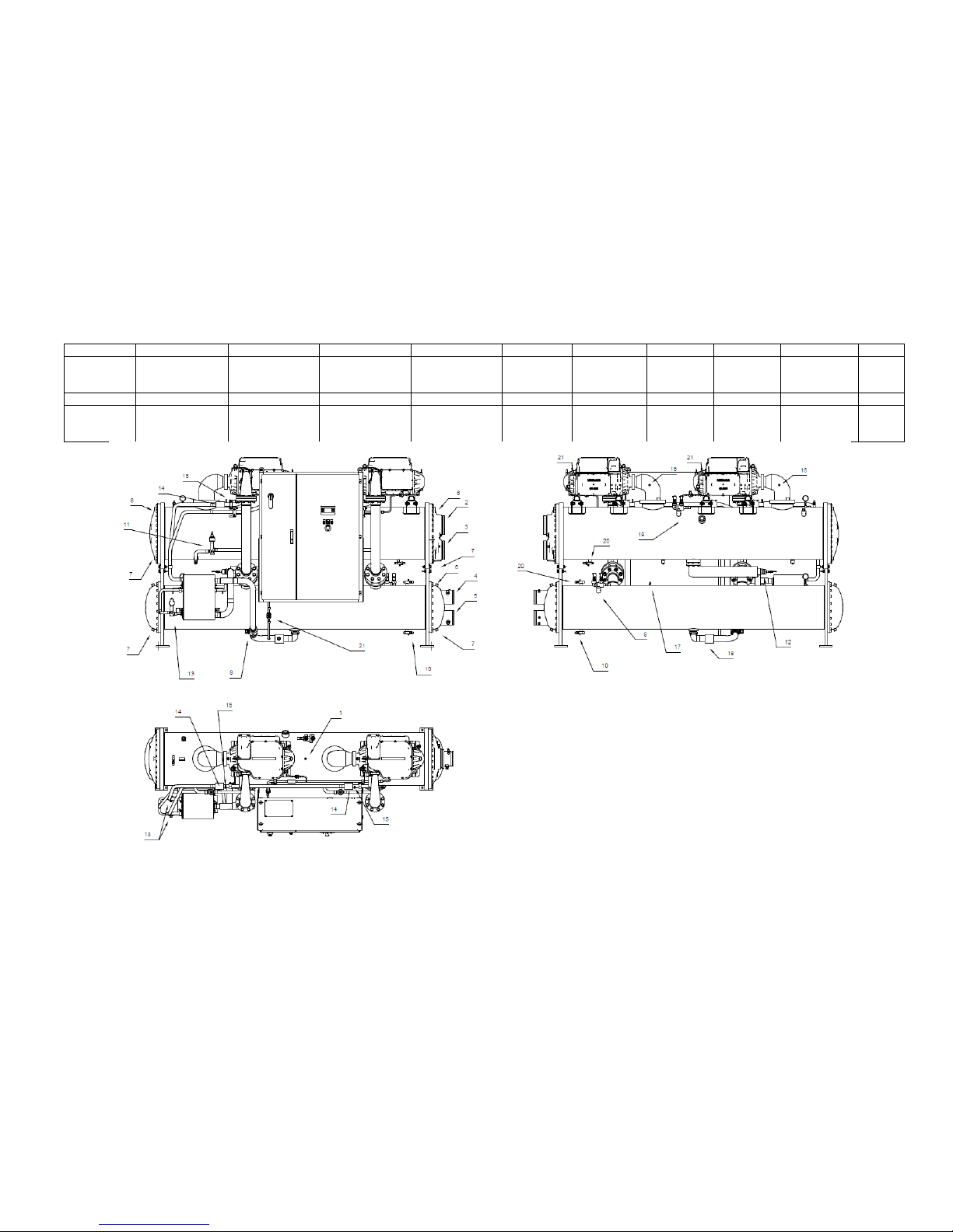
Liquid line
expansion
valve
Economizer line
expansion valve
Economizer line
temperature sensor
Economizer line
pressure
transducer
Suction
temperature sensor
High pressure
transducer
Liquid
temperature
sensor
Low
Pressure
safety valves
Service valve
Inverter cooling
line inlet
Fig. 2 - Dual compressor unit component descriptions
D-EIMWC01405-18EN- 5/32
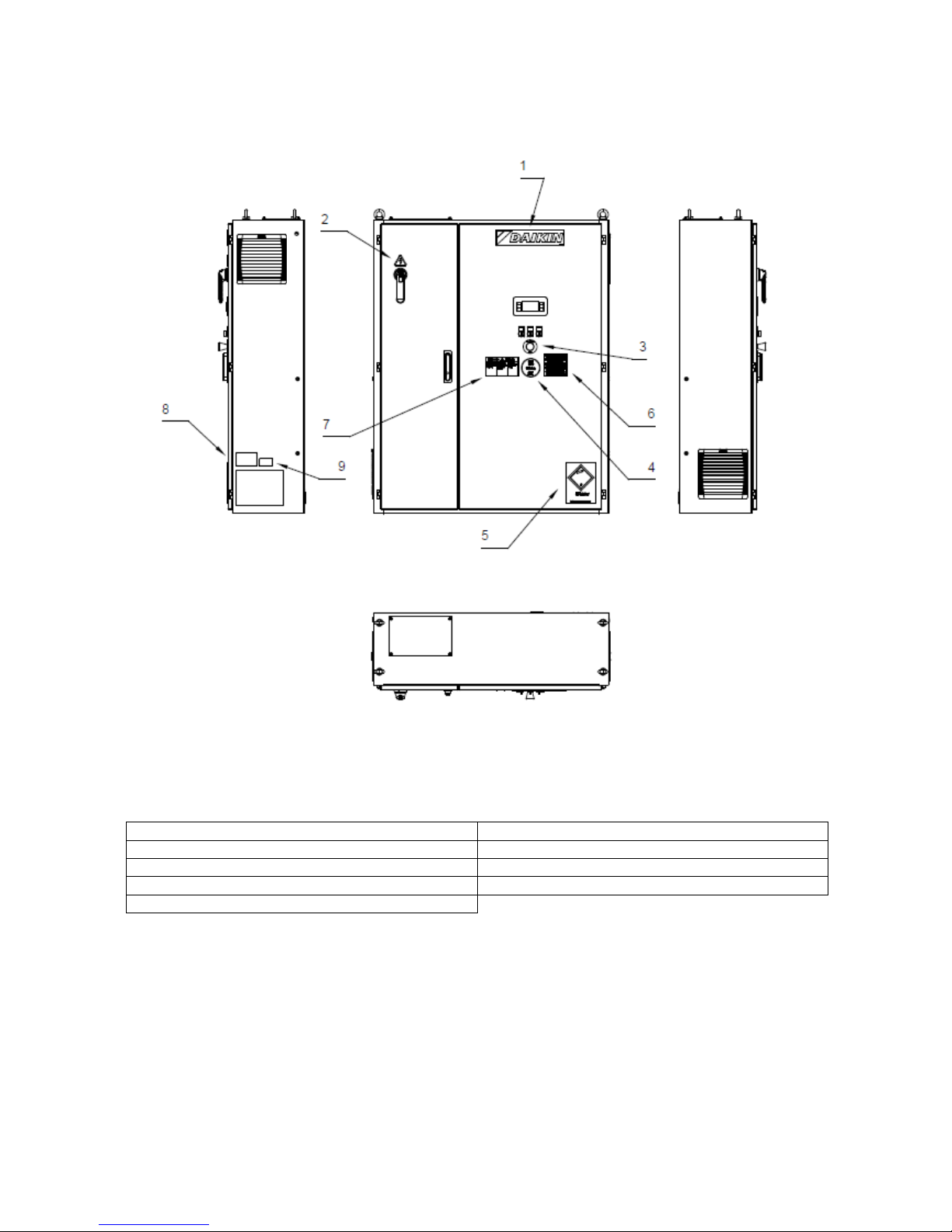
Fig. 3-Description of the labels applied to the electric panel
Identification of labels
1 – Manufacturer’s logo
6 – Wire tightness check
2 – Electricity warning
7 – Shock hazard
3 – Emergency button
8 – Lifting instructions
4 – Type of gas
9 – Unit nameplate
5 – UN 2875

D-EIMWC01405-18EN- 6/32
1 INTRODUCTION
This manual provides information on the functions and standard procedures for all series units and is an important support
document for qualified personnel but can never replace them.
All units are supplied complete with wiring diagrams and dimensional drawings that provide information about the size and
weight of each model.
In case of discrepancies between the content of the manual and the documentation that came with the unit, always rely to
the wiring diagram and dimensional drawings because they are an integral part of this manual.
Read this manual carefully before installing and starting up the unit.
Improper installation can cause: short circuits, leaks, fire or other damages to the equipment or personal injuries.
The unit must be installed by professionals/professional technicians in accordance with current laws of the country of
installation.
The unit must also be started by authorized and trained personnel and all activities must be conducted in accordance and
in full compliance with local standards and laws.
IF THE INSTRUCTIONS IN THIS MANUAL ARE NOT CLEAR, DO NOT INSTALL AND/OR START UP THE UNIT.
If in doubt, for service and further information, contact the manufacturer's authorized representative.
1.1 General Description
Daikin water chillers, with centrifugal compressors and magnetic bearings, are completely factory assembled and tested
before shipment.
The EWWD(H) DZ range consists of models with a single compressor and single cooling circuit (from 320 to 740 kW) and
models with two compressors and single cooling circuit (610 to 1480 kW)
The controller is pre-wired, set and tested at the factory.
Only normal connections are required on site such as piping, electrical connections and pump interlocks, making
installation easier and more reliable. All operating safety and control systems are factory installed in the control panel. The
instructions in this manual apply to all models of this series unless otherwise indicated.
1.2 Application
The EWWD(H) DZ units with centrifugal compressor and adjustment inverters are designed and constructed to cool
buildings or industrial processes. Daikin technicians, specifically trained for this purpose, must start the final system for the
first time. Failure to follow this starting procedure affects the warranty.
The standard warranty covers parts of this equipment with proven defects in material or workmanship. Materials subject to
natural consumption are not, however, covered by the warranty.
The cooling towers used with Daikin units must be selected for a wide scope of application, as described in the "Operating
limits" section. From an energy savings point of view it is always preferable to keep the temperature difference between
the hot circuit (condenser) and the cold circuit (evaporator) to a minimum. However, it is always necessary to verify that
the machine works in the temperature range specified in this manual.
1.3 Information about R1234ze(E)
This product is equipped with refrigerant R1234ze(E) which has minimal impact to the environment, thanks to its low value
of Global Warming Potential (GWP). R1234ze(E) refrigerant is classified by European Directive 2014/68/EU as a Group 2
(non-dangerous) substance, as it is nonflammable at standard ambient temperature and non-toxic. Due to this, no special
precautions are required for storage, transport and handling.
Daikin Applied Europe S.p.A. products comply with applicable European Directives and refer for unit design to product
Standard EN378:2016 and industrial Standard ISO5149. Local authorities approval should be verified referring to European
Standard EN378 and/or ISO 5149 (where R1234ze(E) is classified A2L – Mildly flammable gas).
D-EIMWC01405-18EN- 7/32
Physical characteristics of refrigerant R1234ze (E)
Safety Class
A2L
PED Fluid Group
2
Pratical limit (kg/m3)
0.061
ATEL/ ODL (kg/m3)
0.28
LFL (kg/m3)@ 60°C
0.303
Vapour density @25°C, 101.3 kPa (kg/m3)
4.66
Molecular Mass
114.0
Normal Boling Point (°C)
-19
GWP (100 yr ITH)
7
GWP (ARS 100 yr ITH)
<1
Auto Ignition Temperature (°C)
368
1.4 Installation Safety
All EWWD(H) VZ machines are built in accordance with the main European Directives (Machinery Directive, Low Voltage
Directive, Electromagnetic Compatibility Directive for PED pressurized equipment), make sure you also receive the
declaration of product conformity with the directives along with the documentation.
Before machine installation and commissioning, the people involved in this activity must have acquired the information
necessary to carry out these tasks, applying all the information collected in this book.
Do not allow unauthorized and/or unskilled personnel to access the unit.
Always protect the operating personnel with personal protective equipment appropriate for the tasks to be performed.
Commonly used personal equipment include: protective helmet, goggles, gloves, headphones, safety shoes. Additional
individual and group protective equipment should be adopted after an adequate analysis of the specific risks in the area of
relevance, according to the activities to be performed.
The chiller has to be installed in open air or machinery room (location classification III).
To ensure location classification III a mechanical vent on the secondary circuit(s) has to be installed.
Local building codes and safety standards shall be followed; in absence of local codes and standards refer to EN 3783:2016 as a guide.
In paragraph “Additional guidelines for safe use of R1234ze(E)” there are provided additional informations that should be
added to the requirements of safety standards and building codes.
1.4.1 Additional guidelines for safe use of R1234ze(E) for equipment located in the open air
Refrigerating systems sited in the open air shall be positioned to avoid leaked refrigerant flowing into a building or otherwise
endangering people and property.
The refrigerant shall not be able to flow into any ventilation fresh air opening, doorway, trap door or similar opening in the
event of a leak. Where a shelter is provided for refrigerating equipment sited in the open air it shall have natural or forced
ventilation.
For refrigeration systems installed outside in a location where a release of refrigerant can stagnate e.g. below ground, then
the installation shall comply with the requirements for gas detection and ventilation of machinery rooms.
1.4.2 Additional guidelines for safe use of R1234ze(E) for equipment located in a machinery room
When a machinery room is chosen for the location of the refrigerating equipment it shall be located in accordance with
local and national regulations. The following requirements (according to EN 378-3:2016) can be used for the assessment.
A risk analysis based on the safety concept for the refrigerating system (as determined by the manufacturer and
including the charge and safety classification of the refrigerant used) shall be conducted to determine whether it
is necessary to place the refrigerating system in a separate refrigeration machinery room.
Machinery rooms should not be used as occupied spaces. The building owner or user shall ensure that access
is permitted only by qualified and trained personnel doing the necessary maintenance to the machinery room or
general plant.
Machinery rooms shall not be used for storage with the exception of tools, spare parts and compressor oil for the
installed equipment. Any refrigerants, or flammable or toxic materials shall be stored as required by national
regulations.
Open (naked) flames shall not be permitted in machinery rooms, except for welding, brazing or similar activity
and then only provided the refrigerant concentration is monitored and adequate ventilation is ensured. Such
open flames shall not be left unattended.
A remote switching (emergency type) for stopping the refrigerating system shall be provided outside the room
(near the door). A similar acting switch shall be located at a suitable location inside the room.
All piping and ducting passing throught floors, ceiling and walls of machinery room shall be sealed.
Hot surfaces shall not exceed a temperature of 80 % of the auto-ignition temperature (in °C) or 100 K less than
the auto-ignition temperature of the refrigerant, whichever is higher.
D-EIMWC01405-18EN- 8/32
Refrigerant
Auto ignition temperature
Maximum surface temperature
R1234ze
368 °C
294 °C
Machinery rooms shall have doors opening outward and sufficient in number to ensure freedom for persons to
escape in an emergency; the doors shall be tight fitting, self-closing and so designed that they can be opened
from inside (antipanic system).
Special machinery rooms where the refrigerant charge is above the practical limit for the volume of the room
shall have a door that either opens directly to the outside air or through a dedicated vestibule equipped with
self-closing, tight-fitting doors.
The ventilation of machinery rooms shall be sufficient both for normal operating conditions and emergencies.
Ventilation for normal operating conditions shall be in accordance with national regulations.
The emergency mechanical ventilation system shall be activated by a detector(s), located in the machinery
room.
o This ventilation system shall be:
independent of any other ventilation system on the site.
provided with two independent emergency controls one located outside the machinery room,
and the other inside.
o The emergency exhaust ventilation fan shall:
Be either in the air flow with the motor outside the airflow, or rated for hazardous areas
(according to the assessment).
Be located to avoid pressurization of the exhaust ductwork in the machinery room.
not cause sparks to occur if it contacts the duct material.
o Airflow of the emergency mechanical ventilation shall be at least
𝑉 = 0,014 × 𝑚
2
3
⁄
where
V
is the air flow rate in m3/s;
m
is the mass of refrigerant charge, in kg, in the refrigerating system with the largest charge, any
part of which is located in the machinery room;
0,014
is a conversion factor.
o Mechanical ventilation shall be operated continuously or shall be switched on by the detector.
Detector shall automatically activate an alarm, start mechanical ventilation and stop the system when it triggers.
The location of detectors shall be chosen in relation to the refrigerant and they shall be located where the
refrigerant from the leak will concentrate.
The positioning of the detector shall be done with due consideration of local airflow patterns, accounting for
location sources of ventilation and louvers. Consideration shall also be given to the possibility of mechanical
damage or contamination.
At least one detector shall be installed in each machinery room or the occupied space being considered and/or
at the lowest underground room for refrigerants heavier than air and at the highest point for refrigerants lighter
than air.
Detectors shall be continuously monitored for functioning. In the case of a detector failure, the emergency
sequence should be activated as if refrigerant had been detected.
The pre-set value for the refrigerant detector at 30 °C or 0 °C, whichever is more critical, shall be set to 25 % of
the LFL. The detector shall continue to activate at higher concentrations.
Refrigerant
LFL
Pre-set alarm
R1234ze
0,303 kg/m3
0,07575 kg/m3
16500 ppm
All electrical equipment (not only the refrigerating system) shall be selected to be suitable for use in the zones
identified in the risk assessment. Electrical equipment shall be deemed to comply with the requirements if the
electrical supply is isolated when the refrigerant concentration reaches 25 % of the lower flammable limit or
less.
Machinery rooms or special machinery rooms shall be clearly marked as such on the entrances to the room,
together with warning notices indicating that unauthorized persons shall not enter and that smoking, naked light
or flames are prohibited. The notices shall also state that, in the event of an emergency, only authorized
persons conversant with emergency procedures shall decide whether to enter the machinery room. Additionally,
warning notices shall be displayed prohibiting unauthorized operation of the system
The owner / operator shall keep an updated logbook of the refrigerating system.
The optional leak detector supplied by DAE with the chiller should be used exclusively to check
refrigerant leakage from the chiller itself
D-EIMWC01405-18EN- 9/32
2 INSTALLATION
2.1 Storage
Should it be necessary to store the unit prior to installation, it is necessary to observe some precautions.
Do not remove the protective plastic
Do not leave the unit exposed to the elements
Do not expose the unit to direct sunlight
Do not use the machine near a heat source and/or open flame
Keep in places where room temperature is between + 5° C to 55° C (room temperature over the maximum limit
may trigger the safety valve resulting in loss of refrigerant.
2.2 Receiving and handling
Inspect the unit immediately after delivery. In particular, make sure the machine is intact in all its parts and that there are
no deformations due to collisions. Should damages be found upon receipt, immediately file a written complaint with the
carrier.
Machine returns are Ex factory Daikin Applied Europe S.p.A.
Daikin Applied Europe S.p.A. cannot be held liable for any equipment damages incurred during transportation to the place
of destination.
The isolation of the evaporator corners, where the lifting holes are located, are shipped separately and must be assembled
on site after the unit has been permanently installed. Even the anti-vibration supports (optional) are shipped separately.
Make sure these items, if required, are delivered with the unit.
Use extreme caution when handling the unit to prevent damage to the control panel and the refrigerant pipes.
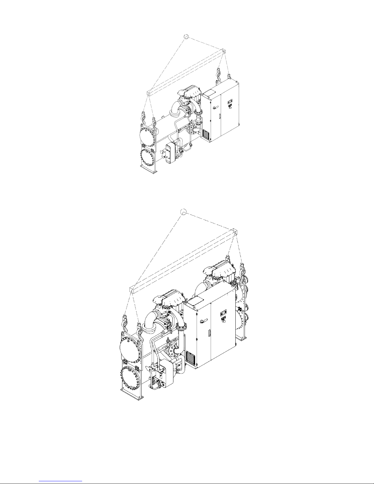
The unit must be lifted by inserting a hook in each of the four corners, where the lifting holes are located (see lifting
instructions). Distancer bars must be used along the line connecting the lifting holes to prevent damages to the electrical
panel and the compressor terminal box (see figure). Do not use any other point to lift the machine.
During the lifting phase, check that the lifting cords and/or chains do not touch the electrical panel and/or piping.
If, to move the machine, slides or moving skates are used, just push the base of the machine without touching the pipes,
compressors and/or electric panel.
Be careful not to hit, during handling, pipes, cables and installed accessories.
All the necessary devices guaranteeing personal safety must be provided during machine handling.
Refer to the dimensional drawing for hydraulic and electrical unit connections.
The overall machine dimensions, as well as the weights described in this manual, are purely
indicative.
The contract dimensional drawing and relevant wiring diagram are provided to the customer when
ordering.
D-EIMWC01405-18EN- 10/32
2.3 Lifting instructions
Single compressor unit
Dual compressor unit
Fig. 1 – Lifting instructions
 Loading...