

Daikin EWWD440AAYNNO, EWWD850AAYNNO, EWWD600AAYNNO Installation And Operation Manual

INSTALLATION AND OPERATION MANUAL
Packaged water-cooled water chillers
EWWD440AAYNNO
EWWD600AAYNNO
EWWD850AAYNNO
**
**
**
.
.
01
02
03
04
05
06
07
08
09
10
ATITIKTIES-DEKLARACIJA
ATBILSTĪBAS-DEKLARĀCIJA
VYHLÁSENIE-ZHODY
CE -
CE -
CE -
CE - UYUMLULUK-BİLDİRİSİ
ZJAVA O SKLADNOSTI
VASTAVUSDEKLARATSIOON
ДЕКЛАРАЦИЯ-ЗА-СЪОТВЕТСТВИЕ
CE - I
CE -
CE -
z vso odgovornostjo izjavlja, da so modeli klimatskih naprav, na katere se izjava nanaša:
kinnitab oma täielikul vastutusel, et käesoleva deklaratsiooni alla kuuluvad kliimaseadmete mudelid:
декларира на своя отговорност, че моделите климатична инсталация, за които се отнася тази декларация:
visiška savo atsakomybe skelbia, kad oro kondicionavimo prietaisų modeliai, kuriems yra taikoma ši deklaracija:
ar pilnu atbildību apliecina, ka tālāk uzskaitīto modeĮu gaisa kondicionētāji, uz kuriem attiecas šī deklarācija:
11
12
13
14
15
16
17
18
19
20
21
22
23
24
25
01
02
03
04
05
06
07
08
09
10
11
12
13
14
15
16
17
18
19
20
21
22
23
24
25
01
02
03
04
05
06
07
08
09
10
11
12
13
14
15
16
17
18
19
20
21
22
23
24
25
01
02
03
04
05
06
07
08
09
10
11
12
13
14
15
16
17
18
19
20
21
22
23
24
25
.
F>
.
.
.
.
.
.
.
Direktive z vsemi spremembami.
Direktiivid koos muudatustega.
Директиви, с техните изменения.
Direktyvose su papildymais.
Direktīvās un to papildinājumos.
Smernice, v platnom znení.
Değiştirilmiş halleriyle Yönetmelikler.
<A> DAIKIN.TCF.013
Direktiver, med senere ændringer.
Direktiv, med företagna ändringar.
Direktiver, med foretatte endringer.
Direktiivejä, sellaisina kuin ne ovat muutettuina.
v platném znění.
Smjernice, kako je izmijenjeno.
irányelv(ek) és módosításaik rendelkezéseit.
z późniejszymi poprawkami.
Directivelor, cu amendamentele respective.
vyhlasuje na vlastnú zodpovednosť, že tieto klimatizačné modely, na ktoré sa vzťahuje toto vyhlásenie:
megfelelnek az alábbi szabvány(ok)nak vagy egyéb irányadó dokumentum(ok)nak, ha azokat előírás szerint használják:
spełniają wymogi następujących norm i innych dokumentów normalizacyjnych, pod warunkiem że używane są zgodnie z naszymi
instrukcjami:
sunt în conformitate cu următorul (următoarele) standard(e) sau alt(e) document(e) normativ(e), cu condiţia ca acestea să fie utilizate în
conformitate cu instrucţiunile noastre
skladni z naslednjimi standardi in drugimi normativi, pod pogojem, da se uporabljajo v skladu z našimi navodili:
on vastavuses järgmis(t)e standardi(te)ga või teiste normatiivsete dokumentidega, kui neid kasutatakse vastavalt meie juhenditele:
съответстват на следните стандарти или други нормативни документи, при условие, че се използват съгласно нашите
инструкции:
atitinka žemiau nurodytus standartus ir (arba) kitus norminius dokumentus su sąlyga, kad yra naudojami pagal mūsų nurodymus:
tad, ja lietoti atbilstoši ražotāja norādījumiem, atbilst sekojošiem standartiem un citiem normatīviem dokumentiem:
sú v zhode s nasledovnou(ými) normou(ami) alebo iným(i) normatívnym(i) dokumentom(ami), za predpokladu, že sa používajú v súlade
s našim návodom:
tamamen kendi sorumluluğunda olmak üzere bu bildirinin ilgili olduğu klima modellerinin aşağıdaki gibi olduğunu beyan eder:
ürünün, talimatlarımıza göre kullanılması koşuluyla aşağıdaki standartlar ve norm belirten belgelerle uyumludur:
оценено положително от <B> съгласно Сертификат <C>.
оценено положително от <E> (Приложен модул <F>) съгласно
21 * както е заложено в Акта за техническа конструкция <A> и
** както е заложено в Акта за техническа конструкция <D> и
(taikomas modulis <F>) pagal pažymėjimą <G>.
Сертификат <G>.
pagal pažymėjimą <C>.
22 * kaip nurodyta Techninėje konstrukcijos byloje <A> ir patvirtinta <B>
** kaip nurodyta Techninėje konstrukcijos byloje <D> ir patvirtinta <E>
23 * kā noteikts tehniskajā dokumentācijā <A>, atbilstoši <B>
.
.
.
. 07 *
<B> KEMA
<C> 71801-KRQ/ECM97-4240
<D> Daikin.TCFP.004
<E> AIB Vinçotte (NB0026)
pozitīvajam lēmumam ko apliecina sertifikāts <C>.
pozitīvajam lēmumam (piekritīgā sadaĮa: <F>), ko apliecina
sertifikāts <G>.
24 * ako je to stanovené v Súbore technickej konštrukcie <A> a kladne
** kā noteikts tehniskajā dokumentācijā <D>, atbilstoši <E>
posúdené <B> podľa Certifikátu <C>.
** ako je to stanovené v Súbore technickej konštrukcie <D> a kladne
posúdené <E> (Aplikovaný modul <F>) podľa Certifikátu <G>.
<F> B+D
25 * <A> Teknik Yapı Dosyasında belirtildiği gibi ve <C> sertifikasına
.
<G> 52846/05/10/01, 52846/06/01/01
göre <E> tarafından olumlu olarak (Uygulanan modül <F>)
değerlendirilmişti.
göre <B> tarafından olumlu olarak değerlendirilmiştir.
** <D> Teknik Yapı Dosyasında belirtildiği gibi ve <G> sertifikasına
.
.
.
.
.
.
.
.
Zandvoordestraat 300, B-8400 Oostende, Belgium
IZJAVA-O-USKLAĐENOSTI
DEKLARACJA-ZGODNOŚCI
DECLARAŢIE-DE-CONFORMITATE
CE - MEGFELELŐSÉGI-NYILATKOZAT
CE -
CE -
CE -
PROHLÁŠENÍ-O-SHODĚ
CE - ERKLÆRING OM-SAMSVAR
CE - ILMOITUS-YHDENMUKAISUUDESTA
CE -
prohlašuje ve své plné odpovědnosti, že modely klimatizace, k nimž se toto prohlášení vztahuje:
izjavljuje pod isključivo vlastitom odgovornošću da su modeli klima uređaja na koje se ova izjava odnosi:
teljes felelőssége tudatában kijelenti, hogy a klímaberendezés modellek, melyekre e nyilatkozat vonatkozik:
deklaruje na własną i wyłączną odpowiedzialność, że modele klimatyzatorów, których dotyczy niniejsza deklaracja:
declară pe proprie răspundere că aparatele de aer condiţionat la care se referă această declaraţie:
erklærer under eneansvar, at klimaanlægmodellerne, som denne deklaration vedrører:
deklarerar i egenskap av huvudansvarig, att luftkonditioneringsmodellerna som berörs av denna deklaration innebär att:
erklærer et fullstendig ansvar for at de luftkondisjoneringsmodeller som berøres av denne deklarasjon innebærer at:
ilmoittaa yksinomaan omalla vastuullaan, että tämän ilmoituksen tarkoittamat ilmastointilaitteiden mallit:
CE - DECLARAÇÃO-DE-CONFORMIDADE СЕ - ЗАЯВЛЕНИЕ-О-СООТВЕТСТВИИ
CE - OPFYLDELSESERKLÆRING
CE - FÖRSÄKRAN-OM-ÖVERENSTÄMMELSE
CE - ¢H§ø™H ™YMMOPºø™H™
CE - DECLARACION-DE-CONFORMIDAD
CE - DICHIARAZIONE-DI-CONFORMITA
‰ЛПТУВИ МВ ·ФОПВИЫЩИО‹ ЩЛ˜ В˘ı‡УЛ fiЩИ Щ· МФУЩ¤П· ЩˆУ ОПИМ·ЩИЫЩИОТУ Ы˘ЫОВ˘ТУ ЫЩ· ФФ›· ·У·К¤ЪВЩ·И Л ·ЪФ‡Ы· ‰‹ПˆЫЛ:
заявляет, исключительно под свою ответственность, что модели кондиционеров воздуха, к которым относится настоящее заявление:
declares under its sole responsibility that the air conditioning models to which this declar ation relates:
erklärt auf seine alleinige Verantwortung daß die Modelle der Klimageräte für die diese Erklärung bestimmt ist:
déclare sous sa seule responsabilité que les appareils d'air conditionné visés par la présente déclar ation:
verklaart hierbij op eigen exclusieve verantwoordelijkheid dat de airconditioning units waarop deze verklaring betrekking heeft:
declara baja su única responsabilidad que los modelos de aire acondicionado a los cuales hace referencia la declaración:
dichiara sotto sua responsabilità che i condizionatori modello a cui è riferita questa dichiarazione:
declara sob sua exclusiva responsabilidade que os modelos de ar condicionado a que esta declaração se refere:
CE - DECLARATION-OF-CONFORMITY
CE - KONFORMITÄTSERKLÄRUNG
CE - DECLARATION-DE-CONFORMITE
CE - CONFORMITEITSVERKLARING
Daikin Europe N.V.
EWWD440AAYNNO**, EWWD600AAYNNO**, EWWD850AAYNNO**,
estão em conformidade com a(s) seguinte(s) norma(s) ou outro(s) documento(s) normativo(s), desde que estes sejam utilizados de
acordo com as nossas instruções:
соответствуют следующим стандартам или другим нормативным документам, при условии их использования согласно нашим
инструкциям:
overholder følgende standard(er) eller andet/andre retningsgivende dokument(er), forudsat at disse anvendes i henhold til vore
instrukser:
respektive utrustning är utförd i överensstämmelse med och följer följande standard(er) eller andra normgivande dokument, under
förutsättning att användning sker i överensstämmelse med våra instruktioner:
respektive utstyr er i overensstemmelse med følgende standard(er) eller andre normgivende dokument(er), under forutssetning av at
disse brukes i henhold til våre instrukser:
are in conformity with the following standard(s) or other normative document(s), provided that these are used in accordance with our
instructions:
der/den folgenden Norm(en) oder einem anderen Normdokument oder -dokumenten entspricht/entsprechen, unter der Voraussetzung,
daß sie gemäß unseren Anweisungen eingesetzt werden:
sont conformes à la/aux norme(s) ou autre(s) document(s) nor matif(s), pour autant qu'ils soient utilisés conformément à nos instructions:
conform de volgende norm(en) of één of meer andere bindende documenten zijn, op voorwaarde dat ze worden gebruikt overeenkomstig
onze instructies:
están en conformidad con la(s) siguiente(s) norma(s) u otro(s) documento(s) nor mativo(s), siempre que sean utilizados de acuerdo con
nuestras instrucciones:
* = , -, 0, 1, 2, 3, ..., 9
sono conformi al(i) seguente(i) standard(s) o altro(i) documento(i) a carattere normativo, a patto che vengano usati in conformità alle
Directives, as amended.
Direktiven, gemäß Änderung.
Directives, telles que modifiées.
Richtlijnen, zoals geamendeerd.
Directivas, según lo enmendado.
Direttive, come da modifica.
√‰ËÁÈÒv, fiˆ˜ ¤¯Ô˘Ó ÙÚÔÔÔÈËı›.
Directivas, conforme alteração em.
Директив со всеми поправками.
*
**
igazolta a megfelelést a(z) <C> tanúsítvány szerint.
igazolta a megfelelést (alkalmazott modul: <F>), a(z) <G>
tanúsítvány szerint.
opinią <B> i Świadectwem <C>.
opinią <E> (Zastosowany moduł <F>) zgodnie ze
Świadectwem <G>.
16 * a(z) <A> műszaki konstrukciós dokumentáció alapján, a(z) <B>
** a(z) <D> műszaki konstrukciós dokumentáció alapján, a(z) <E>
17 * zgodnie z archiwalną dokumentacją konstrukcyjną <A>, pozytywną
** zgodnie z archiwalną dokumentacją konstrukcyjną <D> i pozytywną
Low Voltage 73/23/EEC
Machinery Safety 98/37/EEC
Electromagnetic Compatibility 89/336/EEC
vastaavat seuraavien standardien ja muiden ohjeellisten dokumenttien vaatimuksia edellyttäen, että niitä käytetään ohjeidemme
mukaisesti:
za předpokladu, že jsou využívány v souladu s našimi pokyny, odpovídají následujícím normám nebo normativním dokumentům:
u skladu sa slijedećim standardom(ima) ili drugim normativnim dokumentom(ima), uz uvjet da se oni koriste u skladu s našim uputama:
ob upoštevanju določb:
vastavalt nõuetele:
следвайки клаузите на:
laikantis nuostatų, pateikiamų:
ievērojot prasības, kas noteiktas:
održiavajúc ustanovenia:
bunun koşullarına uygun olarak:
vilket också
<B>
Pressure Equipment 97/23/EEC
som positivt intygas av
<A>
utrustningen är utförd i enlighet med den Tekniska
Konstruktionsfilen
11 *
e giudicato
<C>
<A>
Certificato
secondo il
<B>
og
<A>
som positivt
<D>
Sertifikat <C>
ifølge
) vilket också framgår av
<B>
<F>
<C>
(Fastsatt modul
<E>
Certifikat
<G>
framgår av
i enlighet med den Tekniska Konstruktionsfilen
Certifikat
som det fremkommer i den Tekniske Konstruksjonsfilen
gjennom positiv bedømmelse av
intygats av
**
12 *
ηÈ
ηÈ
<A>
<D>
¶ИЫЩФФИЛЩИОfi <C>
e giudicato
<D>
applicato) secondo il
<F>
Û‡Ìʈӷ Ì ÙÔ
<B>
(Modulo
<E>
apreciate pozitiv de <B> în conformitate cu Certificatul <C>.
18 * conform celor stabilite în Dosarul tehnic de construcţie <A> şi
og
<D>
(Anvendt modul <F>) ifølge
<E>
Sertifikat <G>.
som det fremkommer i den Tekniske Konstruksjonsfilen
gjennom positiv bedømmelse av
**
13 * jotka on esitetty Teknisessä Asiakirjassa <A> ja jotka <B> on
)
e
<F>
<C>
<A>
Certificado
<G>
de acordo com o
(ГЪЛЫИМФФИФ‡МВУЛ ˘ФМФУ¿‰·
<B>
<E>
¶ИЫЩФФИЛЩИОfi
skladu s certifikatom <C>.
apreciate pozitiv de <E> (Modul aplicat <F>) în conformitate cu
Certificatul <G>.
** kot je določeno v tehnični mapi <D> in odobreno s strani <E>
19 * kot je določeno v tehnični mapi <A> in odobreno s strani <B> v
** conform celor stabilite în Dosarul tehnic de construcţie <D> şi
hyväksynyt Sertifikaatin <C> mukaisesti.
hyväksynyt (Sovellettu moduli <F>) Sertifikaatin <G> mukaisesti.
zjištěno <B> v souladu s osvědčením <C>.
14 * jak bylo uvedeno v souboru technické konstrukce <A> a pozitivně
** jotka on esitetty Teknisessä Asiakirjassa <D> ja jotka <E> on
** jak bylo uvedeno v souboru technické konstrukce <D> a pozitivně
e
<D>
и в
) de acordo
согласно
<A>
<F>
<B>
(Módulo aplicado
<E>
<G>
<C>
<G>
Certificado
positivamente da
delineato nel File Tecnico di Costruzione
delineato nel File Tecnico di Costruzione
Certificato
fiˆ˜ ÚÔÛ‰ÈÔÚ›˙ÂÙ·È ÛÙÔ ∞Ú¯Â›Ô ∆¯ÓÈ΋˜ ∫·Ù·Û΢‹˜
positivamente da
06 *
**
under iagttagelse af bestemmelserne i:
enligt villkoren i:
gitt i henhold til bestemmelsene i:
noudattaen määräyksiä:
za dodržení ustanovení předpisu:
prema odredbama:
követi a(z):
zgodnie z postanowieniami Dyrektyw:
în urma prevederilor:
and judged
and judged
<C>
<A>
<D>
Certificate
according to the
<B>
positively by
as set out in the Technical Construction File
following the provisions of:
gemäß den Vorschriften der:
conformément aux stipulations des:
overeenkomstig de bepalingen van:
siguiendo las disposiciones de:
secondo le prescrizioni per:
Ì ًÚËÛË Ùˆv ‰È·Ù¿Íˆv Ùˆv:
nostre istruzioni:
В›У·И Ы‡МКˆУ· МВ ЩФ(·) ·ОfiПФ˘ıФ(·) ЪfiЩ˘Ф(·) ‹ ¿ППФ ¤ББЪ·КФ(·) О·УФУИЫМТУ, ˘fi ЩЛУ ЪФ¸fiıВЫЛ fiЩИ ¯ЪЛЫИМФФИФ‡УЩ·И
Û‡Ìʈӷ Ì ÙȘ Ô‰ËÁ›Â˜ Ì·˜:
EN60335-2-40,
de acordo com o previsto em:
в соответствии с положениями:
01 *
as set out in the Technical Construction File
**
fiˆ˜ ÚÔÛ‰ÈÔÚ›˙ÂÙ·È ÛÙÔ ∞Ú¯Â›Ô ∆¯ÓÈ΋˜ ∫·Ù·Û΢‹˜
ÎÚ›ÓÂÙ·È ıÂÙÈο ·fi ÙÔ
ÎÚ›ÓÂÙ·È ıÂÙÈο ·fi ÙÔ
Û‡Ìʈӷ Ì ÙÔ
**
aufgeführt und von
aufgeführt und von
<C>
<A>
<D>
) according to the
Zertifikat
) positiv ausgezeichnet gemäß
<F>
(Applied module <
<E>
positively by
Certificate <G>
<G>
positiv ausgezeichnet gemäß
(Angewandtes Modul
wie in der Technischen Konstruktionsakte
<B>
wie in der Technischen Konstruktionsakte
<E>
Zertifikat
02 *
**
tal como estabelecido no Ficheiro Técnico de Construção
tal como estabelecido no Ficheiro Técnico de Construção
com o parecer positivo de
com o parecer positivo de
08 *
**
et
et jugé
<A>
<D>
<C>
Certificat
) conformément au
<F>
conformément au
<B>
(Module appliqué
<E>
positivement par
jugé positivement par
tel que stipulé dans le Fichier de Construction Technique
tel que stipulé dans le Fichier de Construction Technique
03 *
**
com o
как указано в Досье технического толкования
Свидетельству
соответствии с положительным решением
09 *
en in orde
en in orde
<A>
<D>
Certificaat <C>
overeenkomstig
<B>
<G>
bevonden door
Certificat
zoals vermeld in het Technisch Constructiedossier
zoals vermeld in het Technisch Constructiedossier
04 *
**
kiidetud <E> järgi (lisamoodul <F>) vastavalt sertifikaadile <G>.
(Uporabljen modul <F>) v skladu s certifikatom <G>.
kiidetud <B> järgi vastavalt sertifikaadile <C>.
** nagu on näidatud tehnilises dokumentatsioonis <D> ja heaks
20 * nagu on näidatud tehnilises dokumentatsioonis <A> ja heaks
Certifikatu <G>.
ocijenjeno od strane <E> (Primijenjen modul <F>) prema
zjištěno <E> (použitý modul <F>) v souladu s osvědčením <G>.
ocijenjeno od strane <B> prema Certifikatu <C>.
** kako je izloženo u Datoteci o tehničkoj konstrukciji <D> i pozitivno
15 * kako je izloženo u Datoteci o tehničkoj konstrukciji <A> i pozitivno
и в
(Прикладной
<D>
og positivt vurderet
og positivt vurderet
<E>
<A>
<D>
<G>
Certifikat <G>
) i henhold til
<F>
Свидетельству
Certifikat <C>
) согласно
<F>
i henhold til
(Anvendt modul
<B>
<E>
af
som anført i den Tekniske Konstruktionsfil
som anført i den Tekniske Konstruktionsfil
модуль
10 *
**
y
y
<A>
<D>
) según el
<F>
Certificado <C>
según el
(Modulo aplicado
<B>
<E>
juzgado positivamente por
tal como se expone en el Archivo de Construcción Técnica
tal como se expone en el Archivo de Construcción Técnica
juzgado positivamente por
05 *
**
af
<G>
Certificado
3PW24367-7C
как указано в Досье технического толкования
соответствии с положительным решением
**
) overeenkomstig
<F>
(Toegepaste module
<E>
bevonden door
Certificaat <G>
Jiro Tomita
Director Quality Assurance
Ostend, 3rd of October 2005
EWWD440AAYNNO**
EWWD600AAYNNO**
EWWD850AAYNNO**
Packaged water-cooled water chillers
Installation and
operation manual
CONTENTS Page
Safety considerations ........................................................................ 1
Precautions during installation................................................................... 1
Precautions when using............................................................................. 2
Precautions when relocating or repairing the unit...................................... 3
Moving and Rigging........................................................................... 3
Inspecting the unit...................................................................................... 3
Lifting the unit............................................................................................. 3
Pulling the unit horizontally ........................................................................4
Description.........................................................................................4
Function of the main components.............................................................. 5
Installation .........................................................................................6
Selection of installation site and foundation work ......................................6
Sound insulation and vibration isolation work............................................ 7
Water quality specifications........................................................................8
Piping work ................................................................................................8
Power supply work ...................................................................................10
Internal wiring - Parts table ......................................................................10
Power circuit and cable requirements ......................................................11
Connection of the watercooled water unit power supply.......................... 11
Interconnection cables............................................................................. 11
Operating the graphic panel display................................................12
Explanation common to respective screens ............................................13
How to change settings of “DATE” and “TIME”.........................................15
How to change settings in the touch panel ..............................................15
Before test run.................................................................................17
Checking the electric circuit (Check the following before power-up) ........ 17
Checking the bridge wiring....................................................................... 17
Check at first electrification...................................................................... 17
Checking the water system...................................................................... 18
Checking the unit body ............................................................................18
Checking the settings on the controller.................................................... 18
Instructions before operation...........................................................19
First operation (Very important) ...............................................................19
Local operation on the unit “LOCAL” ........................................................ 19
Remote operation “REMOTE”.................................................................. 20
Confirming the ON/OFF condition ........................................................... 20
Consulting operational data .....................................................................21
Functions of this model....................................................................21
Automatic water temperature control....................................................... 21
Low load stop (Thermo off)...................................................................... 21
ON-OFF limiting function .........................................................................22
Current limiting function ...........................................................................23
Current demand function .........................................................................23
Units control thermo................................................................................. 24
Compressor starting order rotation function ............................................ 24
2-temperature setting function (Optional) ................................................24
Operation between power failure and power recovery ............................. 25
Unit start flow ...........................................................................................26
Unit stop flow ...........................................................................................28
I/O timing of various contacts................................................................... 29
Maintenance and inspection............................................................ 30
Periodic inspection of safety devices....................................................... 30
Before inspecting .....................................................................................31
Periodical inspection................................................................................ 31
Refrigerant and lubrication oil ..................................................................31
Daily inspection........................................................................................ 32
Disposal requirements .............................................................................32
Cautions when stopping for a long time ..........................................32
Troubleshooting ...............................................................................33
Safety devices.......................................................................................... 34
Operating range...............................................................................35
Operating limit.......................................................................................... 35
Water flow rate......................................................................................... 35
Minimum holding water quantity within the system.................................. 36
Standards for use..................................................................................... 36
How to continue............................................................................... 36
Thank you for purchasing this Daikin air conditioner.
READ THIS MANUAL ATTENTIVELY BEFORE STARTING
UP THE UNIT. DO NOT THROW IT AWAY. KEEP IT IN
YOUR FILES FOR FUTURE REFERENCE.
IMPROPER INSTALLATION OR ATTACHMENT OF
EQUIPMENT OR ACCESSORIES COULD RESULT IN
ELECTRIC SHOCK, SHORT-CIRCUIT, LEAKS, FIRE OR
OTHER DAMAGE TO THE EQUIPMENT. BE SURE ONLY
TO USE ACCESSORIES MADE BY DAIKIN WHICH ARE
SPECIFICALLY DESIGNED FOR USE WITH THE
EQUIPMENT AND HAVE THEM INSTALLED BY A
PROFESSIONAL.
IF UNSURE OF INSTALLATION PROCEDURES OR USE,
ALWAYS CONTACT YOUR DAIKIN DEALER FOR
ADVICE AND INFORMATION.
SAFETY CONSIDERATIONS
For your safety and that of others, observe the precautions listed
here after at all time.
There are two types of precautions:
WARNING: When improper handling or operation could result
in death or serious injury.
CAUTION: When improper handling or operation could result
in injury or physical damage. Depending on the
circumstances, neglecting could lead to serious
consequences.
Both types are extremely important to ensure safety, and must be
payed attention to at all time.
Precautions during installation
WARNING
■ For installation work, be sure to contact your dealer.
Improper installation could result in leaks, electric
shock or fire.
■ Be sure to perform installation work in accordance with
the instructions.
Improper installation could result in leaks, electric
shock or fire.
■ Be sure to install the unit in a level place capable of
holding its weight and fix it with bolts completely.
Incomplete installation or installing in a place that
cannot support the weight of the unit could result in leaks or in
the unit overturning or falling.
■ Ta ke proper measures required for preventing
refrigerant leaks.
If the unit is installed in places such as engine rooms,
countermeasures must be taken against exceeding a certain
concentration of leaking refrigerant. If the concentration limit is
exceeded, it could result in a lack of oxygen.
■ For electrical work, be sure to use a dedicated circuit.
Electrical work should be performed by a qualified
electrician.
Perform the work in accordance with technical standards for
electrical equipment and indoor wiring regulations.
Insufficient circuit capacity of the power supply or improper
electrical work could result in electrical shock or fire.
EWWD440~850AAYNNO**
Packaged water-cooled water chillers
4PW25558-1B
Installation and operation manual
1

■ Use the prescribed cable for wiring, and make sure that
connections are secure.
Be sure to securely fasten cables to their terminals so
that external force on cables has no effect on terminal
connections. Incomplete connection or fixing can lead to heat
generation or fire.
CAUTION
■ Do not install the unit in a place which could be
exposed to leaking of flammable gas.
If gas were to leak and collect around the unit, the gas
could be ignited by the unit.
■ Be sure to install an electrical leakage breaker.
The electrical leakage breaker should conform to
technical standards for electrical equipment and indoor
wiring regulations. Failure to install an electrical leakage breaker
could result in electrical shock.
■ Be sure to provide proper drainage.
Failure to provide proper drainage could result in water
leaking inside and could wet other equipment,
furniture, etc.
■ Apply water-proof to the floor surface where the unit is
to be installed.
Poor water-proof could cause other facility/device to
get wet.
■ Use chilled (hot) water and condenser water that
conforms to the water quality specifications.
Poor quality water could result in water leaks.
■ Do not attempt to run the compressor by pushing the
magnetic contactor with your finger.
Doing so could result in electrical shock or fire.
■ Do not mistake the types of refrigerant and lubrication
oil.
Doing so could result in fire or explosion.
■ Provide proper grounding for the unit.
Do not connect the ground wire to gas piping, water
piping, lightning rods or telephone ground wire.
Improper grounding could result in electrical shock.
■ Be sure to provide each unit with a circuit breaker.
Using a single circuit breaker for more than one unit
could result in electrical shock or fire.
■ Do not run power supply wiring between units.
Doing so could result in fire.
■ Do not expose the unit to humid environments.
The unit should not be installed near hot water springs,
or near the seashore, nor in areas exposed to oil or
corrosive gas atmospheres such as ammonia.
Corrosion caused by such elements can result in electrical
shock or fire.
■ Be sure to dispose of cleansing solutions as stipulated
by law.
Illegal disposal is not only against the law, but can
harm health and the environment.
■ Do not apply any machining to the unit main body, or
do not fit by welding.
Doing so could result in the poor air-tightness and
could result in a lack of oxygen in the latter case.
■ Make sure there is enough service space.
If the space is not enough, maintenance work cannot
be carried out safely, and could result in any injuries.
Precautions when using
WARNING
■ If a malfunction occurs (burning smell, etc.), turn off the
power supply and contact your dealer.
Continuing to operate while the unit is malfunctioning
can result in equipment damage, electrical shock or fire.
■ Do not use any heating medium other than water for
chilled (hot) water and condenser water.
Doing so could result in fire or explosion.
■ Do not turn the unit ON or OFF with the power supply
switch or circuit breaker, etc.
Doing so could result in electrical shock or fire.
■ Ta ke countermeasures against refrigerant leaking.
Ta ke proper countermeasures to prevent refrigerant
leaks from exceeding the concentration limit.
If the concentration limit is exceeded, it could result in a lack of
oxygen.
CAUTION
■ Do not use the unit for any purpose other than for
which it is designed.
The unit should not be used for applications such as
preservation of food, plants or animals, high-tech equipment,
art, etc.
Using the unit for such applications could adversely affect the
quality of these goods.
■ Do not use fuses other than the ones specified.
Using wire, etc., instead of a fuse could result in
equipment damage or fire.
■ Do not attempt to run the compressor by pushing the
magnetic contactor with your finger.
Doing so could result in electrical shock or fire.
■ Do not operate the unit with the cabinet or switch box
cover open.
Doing so could result in electrical shock or fire.
■ Do not operate the unit with wet hands.
Doing so could result in electrical shock.
■ Do not place any inflammable spray nearby. Do not
spray it over the unit.
Doing so could result in fire.
■ Do not attempt to force-operate the unit by short
circuiting safety devices.
Doing so could result in fire.
■ Observe the specified power supply.
If you use a power supply other than specified on the
machine rating plate, it could result in fire or electrical
shock.
■ Do not change settings of safety devices.
Doing so could result in fire, etc.
■ Do not place liquid containers such as flower vases on
the unit.
If the liquid spills out, it could get inside the unit and
cause the electrical insulation to deteriorate, resulting in
electrical shock.
■ Be sure to stop the unit and turn the power supply off
before cleaning.
Failure to do so could result in injury.
■ Do not use chilled (hot) water or condenser water for
drinking or hot water supply.
Doing so could be harmful to health.
■ Do not mistake the types of refrigerant and lubrication
oil.
Doing so could result in fire or explosion.
Installation and operation manual
2
EWWD440~850AAYNNO**
Packaged water-cooled water chillers
4PW25558-1B
■ Do not allow water to remain in the water piping during
prolonged idle periods.
For prolonged idle periods you should fill the water
pipes with antifreeze or drain all the water from the pipes. Failure
to do so could result in leaking.
■ Do not climb or place objects on top of the unit.
Falling or overturning could result in injury.
■ Make sure the unit base is not damaged by prolonged
use.
If damage is not repaired, the unit could fall and result
in injury.
■ Do not wash the unit with water.
Doing so could result in electrical shock.
■ Use chilled (hot) water and condenser water that
conforms to water quality specifications.
Poor quality water could result in water leaks.
■ Never touch parts which tend to become hot such as
compressors and refrigerant piping.
Doing so could result in skin burning.
Precautions when relocating or repairing the unit
WARNING
■ For repairs, be sure to contact your dealer.
Improper repair could result in electrical shock or fire.
■ Do not modify the unit in any way.
Doing so could result in electrical shock or fire.
■ To relocate the unit, be sure to contact your dealer.
Improper installation could result in electrical shock or
fire.
CAUTION
■ Pay attention to ventilation when repairing indoors.
If refrigerant leaks and the room is not sufficiently
ventilated, it could result in accidents caused by lack of
oxygen.
MOVING AND RIGGING
Inspecting the unit
At delivery, the unit should be checked and any damage should be
reported immediately to the carrier claims agent.
The unit comes with 6 rubber vibration isolator pads and 6 metal anti
vibration supports.
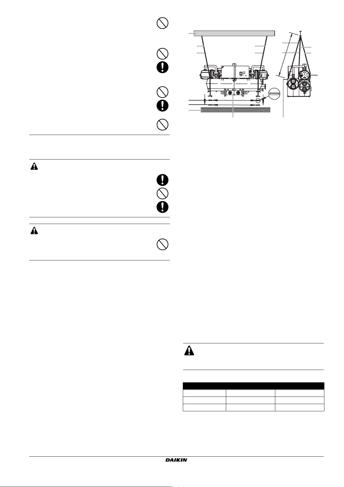
Lifting the unit
1
2 (1)
2 (2)
7
6
2 (3)
2 (4) 2 (4)
8
3
1 Lifting beam
2 Wire rope (L>5 m)
3 Collector under condenser
4 Lifting hole Ø50
5 Protection patches
6 Metal anti vibration support (6 pieces delivered with the unit)
7 Vibration isolation pad (6 pieces delivered with the unit)
8 Foundation
■ Refer to the diagram above. Have the lifting beam (1) and 4 wire
ropes prepared (2). Make sure that wire ropes are longer than
5 m. Be sure to lift the unit horizontally levelled.
■ The unit is shipped with transport stays under it. These have to
be removed before installation.
Pay special attention not to damage the lower collector (3) under
the condenser when removing the transport stays.
■ The condenser and evaporator have lifting holes (Ø50) at both
sides. Use these holes for lifting (4).
■ Perform lifting and transfer the unit slowly avoiding brusque
movements.
The unit is shipped from factory with refrigerant charged.
Brusque movement may result in unexpected behavior of the
product due to inertia force of the liquid refrigerant.
■ Select and use equipment for lifting, including the lifting
beam (1), with a sufficient safety factor. Take offset load into
account that can develop when the product inclines while lifting.
■ For preventing any external damage to the product, we request
you to protect the product by using protection patches (5) where
appropriate.
■ Make sure to first put the 6 metal anti vibration supports (6) and
6 rubber vibration isolation pads (7) in place on the
foundation (8) before putting the unit in its final position. Refer to
"Sound insulation and vibration isolation work" on page 7.
2 (1)
2 (2)
2 (3)
>5 m
4
5
EWWD440~850AAYNNO**
Packaged water-cooled water chillers
4PW25558-1B
■ Do not hang wire ropes on the piping.
Damage of piping and drop of unit may result.
Due to leakage of refrigerant, oxygen deficiency
accident or frostbite may result.
Tab le 1
Model Machine weight (kg) Operation weight (kg)
EWWD440 4200 4430
EWWD600 4650 4900
EWWD850 6100 6450
Before lifting, check the lifting weight stated in the delivery
specification again.
Installation and operation manual
3
Pulling the unit horizontally
■ Ta ke care not to bend the unit base of the chiller.
■ There are copper pipes at the bottom of the unit. Take care to
avoid scrubbing the bottom of the unit. Movement at the slope or
uneven surfaces require special attention.
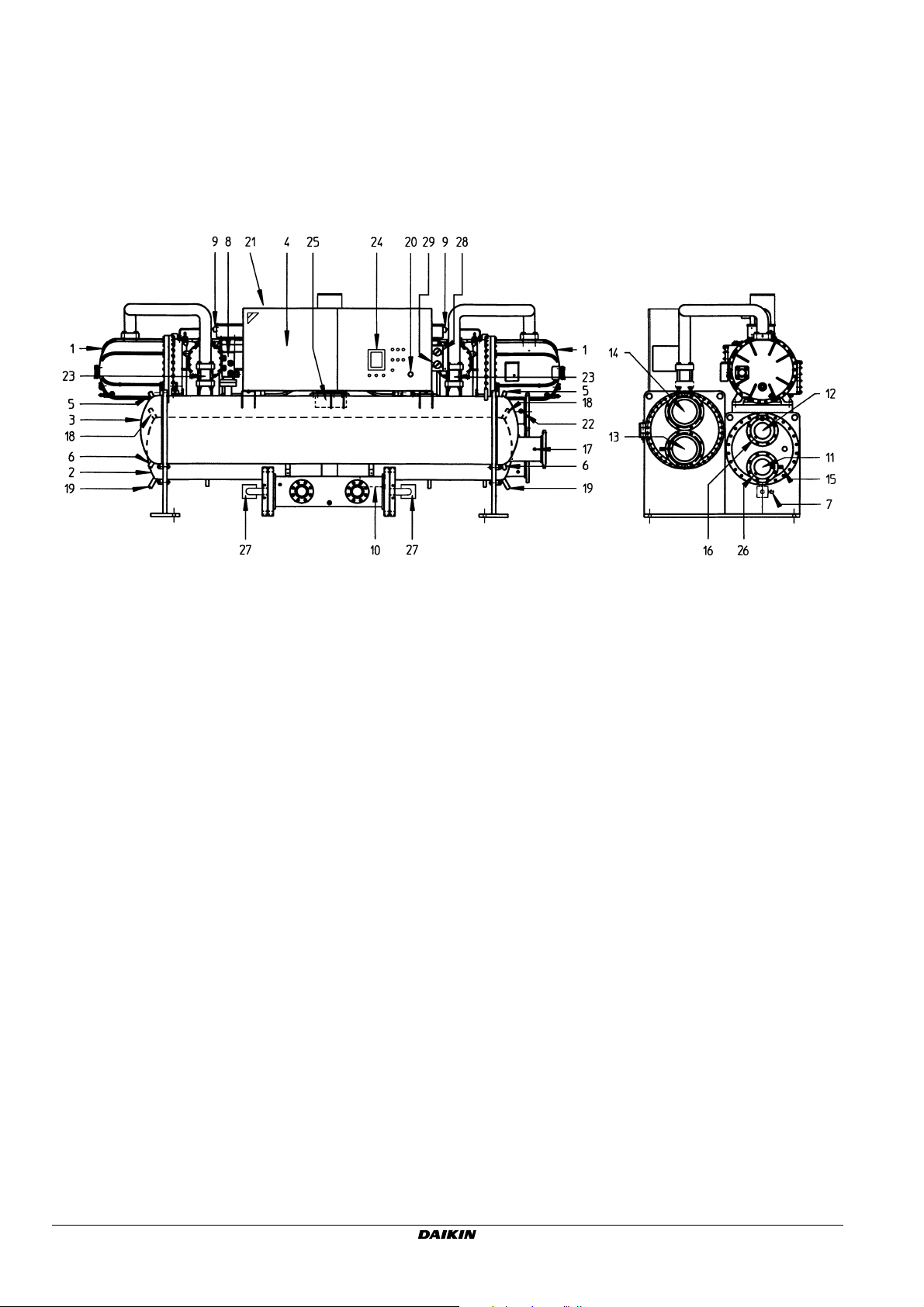
DESCRIPTION
EWWD850
Figure - Main components
1 Compressor 16 Evaporator leaving water temperature sensor
2 Evaporator 17 Condenser entering water temperature sensor
3 Condenser 18 Air purge evaporator
4 Switchbox 19 Water drain evaporator
5 Air purge condenser 20 Emergency stop
6 Water drain condenser 21 Power supply intake and field wiring intake
7 Charge valve 22 Condenser leaving water temperature sensor
8 Safety valve 23 Discharge non-return valve
9 High pressure switches 24 Digital display controller
10 Drier 25 Suction stop valve
11 Chilled water in 26 Evaporator entering water temperature sensor
12 Chilled water out 27 Liquid stop valve
13 Condenser water in 28 High pressure gauge
14 Condenser water out 29 Low pressure gauge
15 Flow switch
Installation and operation manual
4
EWWD440~850AAYNNO**
Packaged water-cooled water chillers
4PW25558-1B

Function of the main components
24
13
14
6
5
6
4
1
8
9
M1C M2C
10
3
2
5
4
1
8
3
2
9
9
12
21
14 14
23
A
13
S.HP
HPS
272
13
23
14
13
20
B
11
S.LP
2
2
17
4
22
25
6
9
13 13 13
16
18
19
9
16
16
Figure - Functional diagram
1 Compressor 15 Stop valve
2 Service valve 16 Service valve
3 Male connector 17 Suction stop valve
4 Stop valve 18 Stop valve
5 Solenoid valve 19 Filter/drier
6 Filter 20 Low pressure transmitter
7 High pressure switch 21 High pressure transmitter
8 Male connector 22 Male connector
9 Solenoid valve 23 One-way valve
10 Ejector 24 Condenser
11 Low pressure gauge 25 Evaporator
12 High pressure gauge
13 Retaining valve A Only for EWWD600+850
14 Safety valve B Only for EWWD850
13 13
1515
B
EWWD440~850AAYNNO**
Packaged water-cooled water chillers
4PW25558-1B
Installation and operation manual
5
As the refrigerant circulates through the unit, changes in its state or
condition occur. These changes are caused by the following main
components:
■ Compressor
The compressor (M*C) acts as a pump and circulates the
refrigerant in the refrigeration circuit. It compresses the refrigerant vapour coming from the evaporator at the pressure at
which it can easily be liquefied in the condenser.
■ Condenser
The function of the condenser is to change the state of the
refrigerant from gaseous to liquid. The heat gained by the gas in
the evaporator is discharged through the condenser to the
water, and the vapour condenses to liquid.
■ Filter/drier
The filter installed behind the condenser removes small particles
from the refrigerant to prevent blockage of the tubes.
The drier takes water out of the system.
■ Expansion valve
The liquid refrigerant coming from the condenser enters the
evaporator via an expansion valve. The expansion valve brings
the liquid refrigerant to a pressure at which it can easily be
evaporated in the evaporator.
■ Evaporator
The main function of the evaporator is to take heat from the
water that flows through it. This is done by turning the liquid
refrigerant, coming from the condenser, into gaseous
refrigerant.
■ Water in/outlet connection
The water inlet and outlet connection allow an easy connection
of the unit to the water circuit of the air handling unit or industrial
equipment.
INSTALLATION
Selection of installation site and foundation work
■ This is a class A product. In a domestic environment this product
may cause radio interference in which case the user may be
required to take adequate measures.
■ Indoor installation: This is an indoor-only model
Do not install this product at places subject to effect of weather
and places exposed to water splash.
Do not install this product at places exposed to direct sunlight.
WARNING
Install this product indoors
Do not install this product at places exposed to water
drop or subject to water splash.
Electric leak or electric shock may result.
■ Well-ventilated installation sites
Set up a ventilation facility so that the leakage of refrigerant
does not lead to oxygen deficiency.
Even in case the capacity of the machine room is big enough to
the extent that leakage of refrigerant does not lead to critical
concentration in terms of volumes, depending on the density
characteristics of the refrigerant gas, places with high
concentration may form locally and oxygen deficiency accidents
may result.
CAUTION
Take measures against refrigerant leakage
■ Ta ke measures so that the critical concentration
is not exceeded when a leakage of refrigerant
takes place.
■ Exceeding the critical concentration due to
leakage of refrigerant may lead to oxygen
deficiency accidents.
Installation and operation manual
6
■ An atmosphere with flammable gas is not allowed.
Because this product is not explosion-proof, do not install this
product at places in atmospheres with flammable gas or places
with risk of leakage of flammable gas.
CAUTION
Do not install this product at places with risk of
leakage of flammable gas.
Accumulation of flammable gas around the unit due to
leakage of flammable gas may lead to ignition.
■ Avoid installing this product at high temperature or low
temperature places and at places with high humidity.
Avoid installing this product where the temperature exceeds
35°C or temperature only reaches 0°C or less.
Avoid installing this product at places with relative humidity of
90% or more.
Mounting this product at places where the temperature variation
per hour exceeds 8°C or more is also inappropriate.
If you use this product in cold climates, consideration must be
given not only to the unit but also to freezing of chilled and
cooling water facilities.
■ Do not install this product near a flame
As a rule, install this product in a separate room away from
flame facilities including boilers, etc.
When you install this product in the same room where a boiler is
placed, restriction may arise on the installation conditions.
Therefore, please consult with the responsibles of competent
public agencies before doing so.
■ Special atmosphere is not allowed
Do not install the unit in atmospheres that attack metal, electric
parts, etc.
Be careful with the installation site of the cooling tower so that
the cooling water does not become highly corrosive.
If installed in the vicinity of contaminated rivers, seaside, plating
plant and chemical plant, or main roads, take care to protect the
cooling tower from inhaling harmful gases directly and increase
the frequency of water examination.
Do not install this product near ammonia facilities, exhaust ports
of toilets or exhaust ports of operating rooms of hospitals,
sewage treatment facilities, etc.
Gas leakage accident due to corrosion of heat exchanger tubes
of the condenser may result.
CAUTION
Do not install the unit in special atmospheres
Do not install this product in hot spring resorts,
seaside areas, oily places or atmosphere with
corrosive gases including ammonia. Electric shock or
fire due to corrosion may result.
■ Avoid installing this product in places where sound or vibration
can present problems.
Select a place where operating sound or vibration does not
present possible problems.
In response to such conditions, take proper measures for
vibration isolation and sound insulation.
Vibration may propagate from the installation and produce
sound from floor or wall.
In living areas, special attention is required when you install the
unit in upper stories of a building.
■ Fix the unit with bolts on a flat place that bears the weight of the
unit sufficiently.
Set the unit on a solid and level foundation (the levelness should
be ≤2 mm/1000 m).
WARNING
Fix the product correctly with anchor bolts on a
flat foundation that bears the weight of the unit.
Insufficient strength of the foundation and insufficient
fixing may result in water leakage or a roll-over
accident.
EWWD440~850AAYNNO**
Packaged water-cooled water chillers
4PW25558-1B
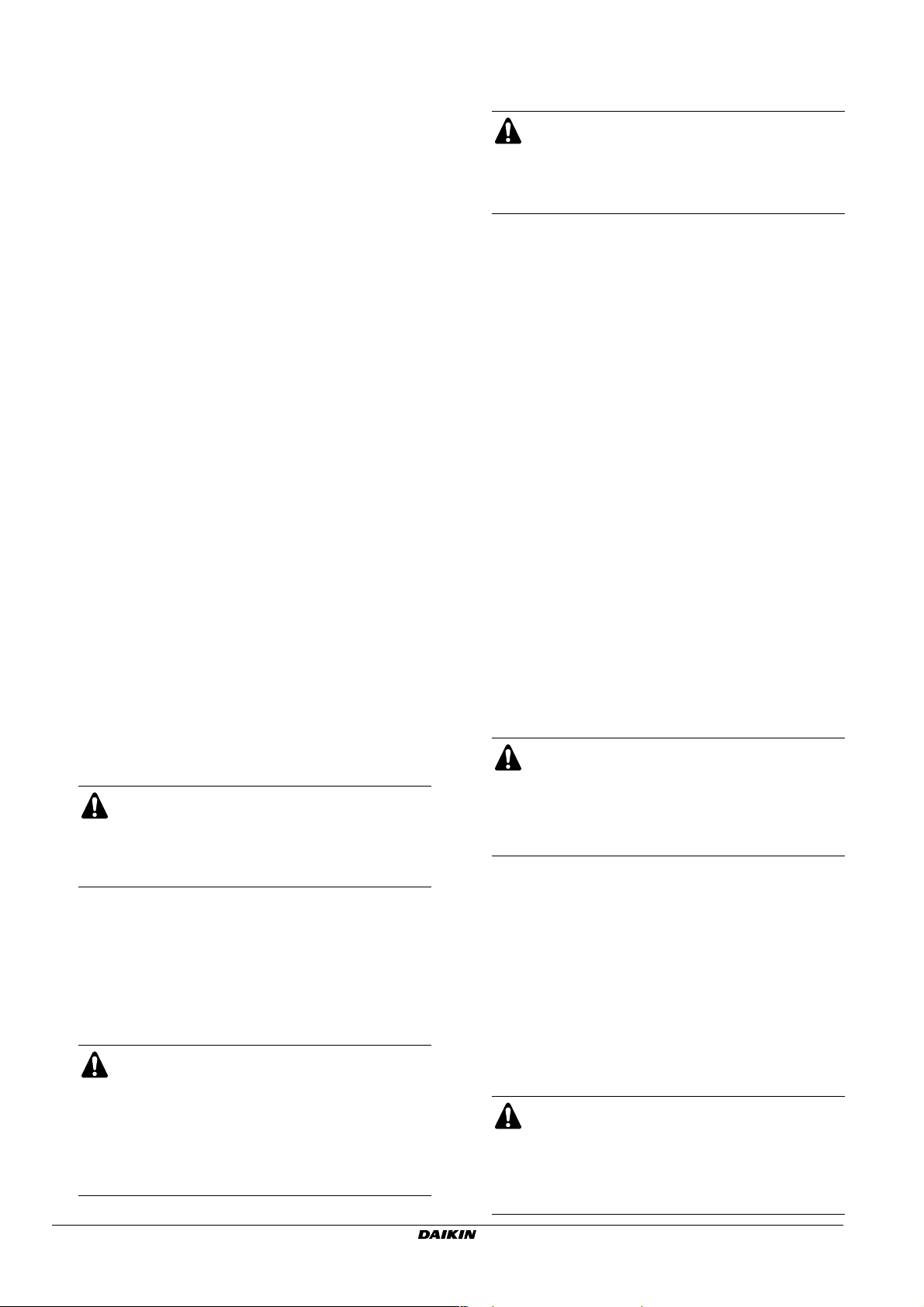
■ Provide for sufficient service space.
A
1
2
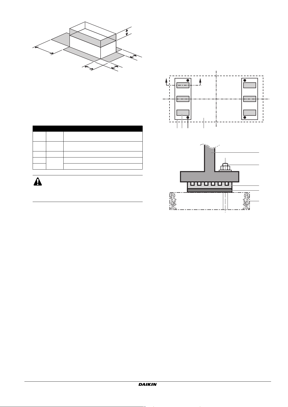
■ Perform the vibration isolation in function of the installation site.
This machine comes with vibration isolation pads and metal anti
vibration supports as a standard. Position of vibration isolation
E
pads and metal anti vibration supports as on the foundation
drawing results in a sufficient degree of vibration isolation.
However, when vibration is critical, like at middle stories of the
building, take proper vibration isolation measures with spring
vibration isolating devices.
This machine comes with 6 vibration isolating pads and 6 metal
D
B
C
anti vibration supports. Lay them down near foundation bolts
and near the center of the unit base. (See the following figure)
1 Unit
2 Front side – switch box side
A From the leftmost end of the equipment
B From the rightmost end of the equipment
C From the frontmost of the equipment
D From the backmost of the equipment
E From the top of the equipment
Service space dimensions
A ≥3000
B ≥500
C ≥1200 Required at front side
D
≥500
E Required for maintenance of compressor
Required in the direction of the length or side to
side (space for pulling out tubes)
Required both in the direction of the length and
side to side
Backside maintenance space
CAUTION
Provide for enough service space.
Insufficient space does not allow safe maintenance
and may lead to injury.
■ Pay attention to the drain
Make foundation of the unit higher than the surrounding.
For machine maintenance, the floor should be treated with
water-proofing. The drainage ditch should be provided around
the foundation. Equip the drain ditch with drain piping. Avoid
installing the unit in a place where overhead flooding or
submersion is expected during flood.
■ Pay attention to lighting
For the sake of performing daily maintenance provide for
efficient lighting around the unit.
Unit front (Switch box side): ≥100 lux.
Surrounding of the unit except for the above: ≥80 lux.
■ For further information about foundation dimensions, see the
foundation drawing to perform correct work.
AA
12+34 5
A-A
1
4
2
3
5
1 Unit base
2 Vibration isolating pad
3 Metal anti vibration support
4 Foundation anchor bolt
5 Foundation
Sound insulation and vibration isolation work
■ Be careful with the reflected sound
Sound in the machine room may get higher due to the effect of
reflected sound and interference with operating sound of other
equipment, etc. Take appropriate sound absorption and sound
insulation measures.
■ Preventing the vibration propagation through piping
Unit vibration may propagate through chilled water piping,
cooling water piping and relief valve discharge pipes. Sound/
vibration problems may result in unexpected places.
Perform the isolation of vibration by using expansion joints
immediately near the unit.
EWWD440~850AAYNNO**
Packaged water-cooled water chillers
4PW25558-1B
Installation and operation manual
7
Water quality specifications
The quality of chilled (hot) water largely affects the performance and
life time of this unit. It is therefore very important to check the water
quality before using it, and to keep monitoring the quality of water
after installing the unit.
Water quality standard values for the water shall be as in the table.
condenser water evaporator water heated water
circulating system
circulating
Items to be controlled
pH at 25°C 6.5~8.2 6.0~8.0 6.8~8.0 6.8~8.0 6.8~8.0 7.0~8.0 7.0~8.0 (C)
Electrical conductivity [mS/m] at 25°C <80 <30 <40 <40 <30 <30 <30 (C)
Chloride ion [mg Cl–/l]
Sulfate ion [mg SO
M-alkalinity (pH 4.8) [mg CaCO3/l]
Total hardness [mg CaCO3/l]
Calcium hardness [mg CaCO3/l]
Silica ion [mg SiO2/l]
Items to be referred to
Iron [mg Fe/l] <1.0 <0.3 <1.0 <1.0 <0.3 <1.0 <0.3 (C)
Copper [mg Cu/l] <0.3 <0.1 <1.0 <1.0 <0.1 <1.0 <0.1 (A)
Sulfide ion [mg S2–/l]
Ammonium ion [mg N
Remaining chloride [mg Cl/l] <0.3 <0.3 <0.3 <0.3 <0.3 <0.25 <0.3 (A)
Free carbide [mg CO2/l]
Stability index 6.0~7.0 ——————(C)
(A) corrosion (B) scale (C) corrosion+scale
2
–/l
4
water
<200 <50 <50 <50 <50 <50 <50 (A)
<200 <50 <50 <50 <50 <50 <50 (A)
<100 <50 <50 <50 <50 <50 <50 (B)
<200 <70 <70 <70 <70 <70 <70 (B)
<150 <50 <50 <50 <50 <50 <50 (B)
<50 <30 <30 <30 <30 <30 <30 (B)
+
<1.0 <0.1 <1.0 <1.0 <0.1 <0.3 <0.1 (A)
/l]
4
<4.0 <4.0 <4.0 <4.0 <4.0 <0.4 <4.0 (A)
supply water
not detectable not detectable not detectable not detectable (A)
once through
system
once through
water
circulating
water
[<20°C]
supply water
low temperature
circulating
water
[20°C~60°C]
supply water
tendency if
out of criteria
2. Supplying a proper flow to the unit
CAUTION
Use chilled/hot water and condenser water that
complies with water quality specifications.
Deterioration of water quality may lead to water leakage,
etc.
A circulation pump must be provided in such a way that it
discharges the water directly into the evaporator.
■ Pump interlocks must be installed in the water
outlet pipe to prevent the unit from operating at a
water flow which is too low. 3 terminals are
provided in the switch box for the electrical
Piping work
connection of the pump interlock.
■ Improper installation of the pump interlock can
result in severe damage of the equipment.
All field piping must be installed by a licensed refrigeration
technician and must comply with relevant local and
national regulations.
■ A wire mesh strainer must be installed at the inlet
of the heat exchanger to protect the heat
■ The units are equipped with a water inlet and water outlet for
connection to a chilled water circuit. This circuit must be
provided by a licensed technician and must comply with all
relevant European and national regulations.
■ The evaporator and condenser are foreseen of flanges for the
exchanger from foreign matter. Distance between
the inlet of the heat exchanger and the wire mesh
strainer must be <0.5 m.
■ Improper installation of the wire mesh strainer will
result in severe damage of the equipment.
water inlet and outlet (refer to the outlook diagram). Evaporator
and condenser water connections are to be made in accordance
with the outlook diagram, respecting the water in- and outlet.
If air, moisture or dust gets in the water circuit, problems may
occur. Therefore, always take into account the following when
connecting the water circuit:
1. Use clean pipes only.
2. Hold the pipe end downwards when removing burrs.
3. Cover the pipe end when inserting it through a wall so that no
dust and dirt enter.
Before continuing the installaiton of the unit, check the following
points:
1. Measures against vibration
■ Mount the expansion joint near the unit so that operation
vibration of the unit does not propagate to the equipment
3. Removing foreign materials
■ Periodic cleaning of the scale adhered to the inside of the
unit is required.
For the sake of facilitating the cleaning, provide the water
piping system with stopvalves at both inlet and outlet sides.
In addition, for ease of opening the water chamber of the
condenser and evaporator, we recommend to use short
pipes with flanges at both the water piping side and the unit
side.
■ For periodic cleaning and maintenance, provide valves for
release to atmosphere, drain off valves and valves for
chemical cleaning between stopvalves provided in the water
piping system and the unit body.
For drain off valves, lay down the drain piping to the drain
ditch.
system.
■ Equip the piping with supports at appropriate points.
Installation and operation manual
8
EWWD440~850AAYNNO**
Packaged water-cooled water chillers
4PW25558-1B
4. Prevent from getting mixed air into the system
1
1
■ Install the air purge valves at proper positions so that the air
purge of the entire equipment system is possible.
Operation of units with air mixed may lead to deterioration in
performance, actuation of protective devices, or damage of
heat exchanger tubes.
■ Pay attention to the flow velocity inside the water system,
position of the expansion tank, and to the position of air
purges along the piping, so that cavitations do not occur.
■ This machine is designed on the precondition that circulating
water is used. Use of once-through water may lead to
damage of the heat exchanger tubes due to dissolved
oxygen or free carbonate in chiller water (hot water) systems.
■ When using the unit in a heat recovery application, additional
care must be taken that water flow rate does not get
excessive. In the same application, a deaeration treatment
unit must be installed.
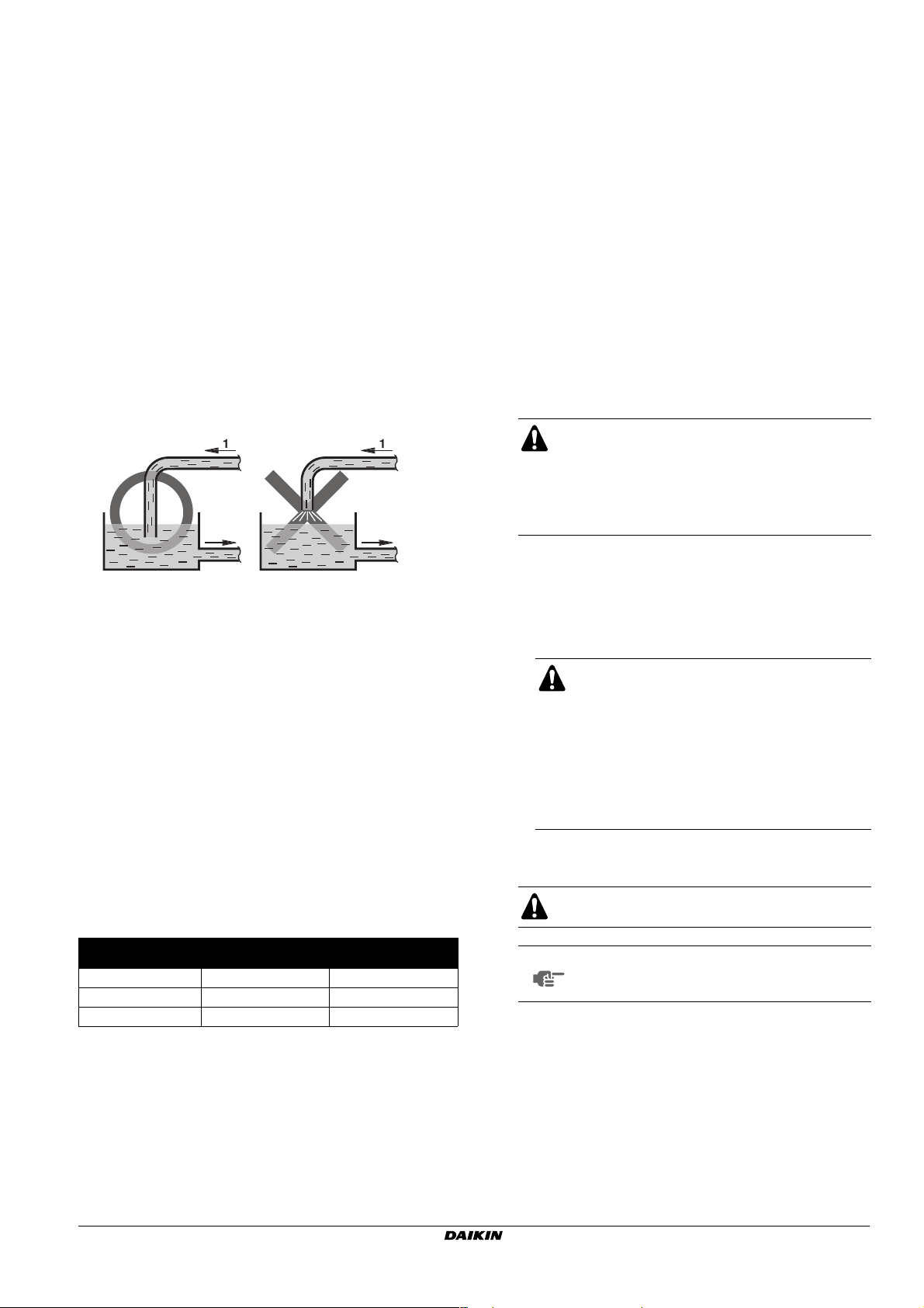
■ Do not allow aeration along the cooling water system as
shown in the following diagram.
Aerating water causes the dissolved oxygen to increase, and
pollutants in the atmosphere condensed in the water cause
the water to become corrosive.
■ Avoid execution of piping in such a way that a draft line is
formed inside the condenser or evaporator while the unit is
operating or stops.
■ In case of semi hermetic chilled water system with a thermal
storage tank, perform periodic replacement of water and
cleaning and inspection of the bottom of the thermal storage
tank (once every 1 or 2 years).
A new concrete heat storage tank will give off ions, and it is
not seldom that pH of the heat storage tank water rises
above 10. If pH rises above the standard, the rate at which
copper corrodes increases. The water must be changed
before the pH reaches that level.
If a heat storage tank is used for a prolonged period,
springing and leaking of water could occur due to cracks in
the heat storage tank. Water leaks pose no serious problem
for water quality, but if seawater or dirty underground water
springs, it could cause an outbreak of microorganisms in the
water of the heat storage tank, thus producing slime in the
system. It could also cause calcium carbonate to adhere.
■ Make sure to perform periodic water quality inspections,
especially as to water quality of the cooling water. Insufficient
water quality may result not only in performance deterioration
of the unit but also in damage to the heat exchanger tubes.
CAUTION
Use chilled (hot) water/cooling water that
complies with the water quality standard as in
chapter "Water quality specifications" on page 8.
Deterioration of water quality may lead to water
leakage and damage to the heat exchanger tubes.
1 Discharge pipe
2 Inlet pipe
5. Observing the operation range of the unit
■ Observe the maximum operating water pressure of the unit.
■ Pay attention so that the cooling water inlet temperature
reaches 25°C or more.
When you use the unit during intermediate season and
winter season, control the cooling water supply water
temperature by using a thermostat for the cooling water inlet
and a 3-way mixing valve.
■ Pull-down time of this machine (time required for cooling from
ordinary temperature to reach the recommended operating
range) is within 1 hour under no load condition.
Make sure to prevent the water flow from becoming to high.
■ To assure proper operation of the unit a minimum water
volume is required in the system and the water flow through
the evaporator must be within the operation range as
specified in Ta ble 2.
Tab le 2: Minimum water volume
Minimum water
Model
EWWD440 2660 105
EWWD600 3710 110
EWWD850 5020 157
volume (l)
Water quantity inside the
evaporator (l)
7. Freeze-up protection
■ The complete water circuit, inclusive all piping, must be
insulated to prevent condensation and reduction of the
cooling capacity.
■ Protect the water piping against water freezing during winter
period (e.g. by using glycol solution or heatertape).
CAUTION
Do not confuse the connection of outlet and
inlet of the water piping.
■ Do not confuse the inlet and outlet of the
chilled water and connection position of the
condenser water.
■ Normal operation may get impossible.
■ It may lead to breakdown including freezing
fracture of heat exchanger tubes.
8. Preventing excessive increase of chilled water and condenser
water temperature
The water pressure should not exceed the maximum
working pressure of 10 bar.
NOTE
Provide adequate safeguards in the water circuit
to make sure that the water pressure will never
exceed the maximum allowable working pressure.
■ When it is impossible to secure the minimum holding water
quantity, increase of thermo differential value is required. For
how to change the differential value, see "Settings screen" on
page 14 and "Target temperature and low load stop related
settings screen" on page 22.
6. Prevent corrosion of water piping and of the unit interior
■ Do not install the earth of the electric equipment to the water
piping. Corrosion due to electric corrosion may occur.
■ If piping is to be put underground, be extremely careful and
take dust preventive measures.
EWWD440~850AAYNNO**
Packaged water-cooled water chillers
4PW25558-1B
Installation and operation manual
9
Power supply work
All field wiring and components must be installed by a
licensed electrician and must comply with relevant
European and national regulations.
The field wiring must be carried out in accordance with the
wiring diagram supplied with the unit and the instructions
given below.
Be sure to use a dedicated power circuit. Never use a
power supply shared by another appliance.
Internal wiring - Parts table
Refer to the internal wiring diagram supplied with the unit. The
abbreviations used are listed below:
20R3, 20R4 ............Oil return solenoid valve circuit 1, circuit 2
20R8.......................Dryer line solenoid valve
20R1, 20R2 ............Forcely closed solenoid valve circuit 1, circuit 2
20R5, 20R6 ............Equalizing oil level solenoid valve circuit 1,
circuit 2
20R7.......................Float chamber gas purging solenoid valve
20R9.......................Ejecter solenoid valve
26WE .....................Chilled water overcooling sensor
2-88X......................Auxiliary relay run/stop monitor
42-1, 42-2...............Deltacontactor for circuit 1, circuit 2
49C1, 49C2 ............Thermal protector compressor motor circuit 1,
circuit 2
51C1, 51C2 ............Overcurrent relay for circuit 1, circuit 2
52-1, 52-2...............Linecontactor for circuit 1, circuit 2
52X-1, 52X-2 ..........Auxiliary relay for circuit 1, circuit 2
5X-1, 5X-2 ..............Compressor circuit error relay for circuit 1,
circuit 2
5X-3........................Common error relay
6-1, 6-2...................Starcontactor for circuit 1, circuit 2
63CH-1~4...............High discharge pressure sensor
63WEL ...................Chilled water interruption sensor
88CH ......................High discharge pressure relay
88CHX....................High discharge pressure auxiliary relay
88WCX...................condenser water pump run/stop relay
88WE .....................Chilled water overcooling relay
88WEX ...................Chilled water pump run/stop relay
AXP1, AXP2...#.....Pumpinterlock
BS ..........................PCB-controller
BS1 ........................Local stop push button
BS2 ........................Local run push button
CH1, CH2...............Oil heater for circuit 1, circuit 2
CT1, CT2................Current transfo
CT-T1, CT-T2..........Current transducer 5 A/5 V; 24 V DC
F11U~F13U....# .....Main fuses
F21U~F23U....# .....Main fuses
F10S, F11S ............Circuit breakers with fuses for circuit 1, circuit 2
GL1 ........................Indication lamp: unit stop
GP ..........................Display
H1P, H2P........*......Indication lamp: run/stop remote display
H3P ................*......Indication lamp: common error remote display
H4P, H5P........*......Indication lamp: compressor error 1, 2 remote
display
H6P.................* ..... Indication lamp: condenser water pump run/stop
H7P.................* ..... Indication lamp: chiller water pump run/stop
HF1-2..................... Fuse for primary of TR1
HF3.1, 3.2.............. Fuse for reverse phase protector
KP1, KP2............... Compressor slide valve position sensor for circuit
1, circuit 2
M1C, M2C ............. Compressor motors circuit 1, circuit 2
MCCB1.................. Automate fuse for secundary of TR1
NF1........................ EMC-filter for power supply PCB
NF2~NF4............... Ferrite
ÖL.......................... Indication lamp: error
PBS ....................... Common error reset push button
PE.......................... Main earth terminal
R2-1, R2-2............. Auxiliary relay: error compressor-motor overload-
phase sequence
RL1........................ Indication lamp: unit running
RL2, RL3 ............... Indication lamp: compressor running for circuit 1,
circuit 2
RL4........................ Indication lamp: remote operation
RPP.1, RPP.2 ......... Reverse phase protector for circuit 1, circuit 2
S5E........................ Emergency stop
S6S.................*..... Switch: remote start/stop
S10S...............*..... Switch: demand control ON/OFF
S12S, S14S....* ..... Push button: remote run, remote stop
S13S...............# .... Main isolator switch
Sen H..................... Discharge pressure sensor
Sen L ..................... Suction pressure sensor
T2 .......................... Time relay; time delay / 0.5 s
Th1, Th2 ................Compressor discharge gas temperature for
circuit 1, circuit 2
Th3 ........................ Discharge gas temperature sensor
Th4 ........................ Chilled water inlet temperature sensor
Th5 ........................ Chilled water outlet temperature sensor
Th6 ........................ Condenser water inlet temperature sensor
Th7 ........................ Condenser water outlet temperature sensor
TR1........................ Transfo control circuit
WL ......................... Indication lamp: power supply
Not included with standard unit
Not possible as option
Obligatory #
Not obligatory *
Installation and operation manual
10
EWWD440~850AAYNNO**
Packaged water-cooled water chillers
4PW25558-1B
 Loading...