

EHVH04CB3VF
EHVH08CB3VF
We advise to first carefully read this addendum and only then to consult delivered manuals and proceed with installation of the unit.
For this floor standing low temperature heat pump EHVH04CB3VF or EHVH08CB3VF, instructions in the manuals delivered with the unit are these
of the EHVH04CB3V or EHVH08CB3V.
All delivered manuals as well as the Installer reference guide and User reference guide referred to in delivered manuals apply, but there are some
exceptions and attention points for the “F”-version units.
These exceptions and attention points are described in this addendum.
Differences mainly relate to
1) water piping and refrigerant piping connections (see pictures in this addendum);
2) the built-in 12 l flow-through vessel under the domestic hot water tank (which impacts on the minimum water volume of the installation);
3) lay-out of the internal piping;
4) impact of these differences on technical specification drawings. The correct versions are therefore added to this addendum.
There is no difference for everything related to the user interface, the software or the operation of the unit. All information in the delivered manual
related hereto is therefore correct.
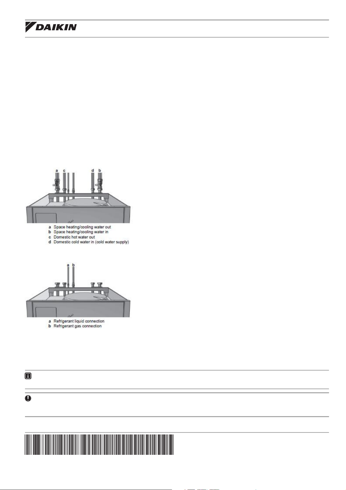
1. Water piping connections and refrigerant piping connections
The following picture illustrates the water piping connections of your unit (chapter “To connect the water piping”). Analogous pictures in the
EHVH04/08CB3V manual are to be neglected.
Addendum to the documentation set
The following picture illustrates the refrigerant piping connections of your unit (chapter “To connect the refrigerant piping to the indoor unit”).
Analogous pictures in the EHVH04/08CB3V manual are to be neglected as well.
2. Minimum water volume (chapter “To check the water volume and flow rate)
ONLY applicable for EHVH04+08S18CB3VF
The system does not require a minimum water volume. Since an extra flow-through vessel is built into the unit, the total water volume in the
installation can be 0 l. It is however required that when all heat emitters are closed, the user interface displays a minimum water flow of 15 l/min.
INFORMATION
Critical processes or rooms with a high heat load may require extra water.
NOTICE
When circulation in each space heating loop is controlled by remote controlled valves, it is important that a minimum water flow of 15 l/min is
guaranteed, even if all valves are closed.
*4P412945-1 0000000N*
Addendum to the documentation set
1
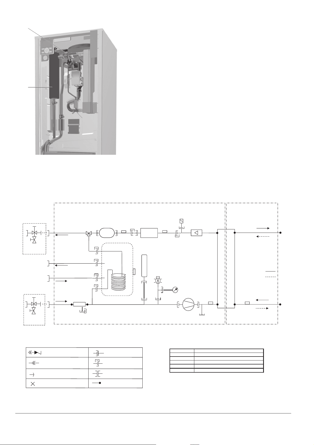
3. Lay-out of internal piping
a
b
a Flow sensor
b Backup heater
4. Impact of these differences on technical specification drawings (chapter “Technical data” of the Installer reference guide referred to in
delivered manuals)
Piping diagram: Indoor unit
Space heating
water out
FIELD INSTALLED
shut off valve
with drain/fill
valve
Domestic hot water:
hot water out
Domestic hot water:
cold water in
FIELD INSTALLED
Filter
Flow-through
vessel
R2T
Domestic Hot Water Tank
Heat exchanger
R5T
BUH
Expansion
vessel
Safety
valve
R1T
Air purge
Flow sensor
Manometer
Pump
R4T
REFRIGERANT SIDE WATER SIDE
Plate heat
exchanger
REFR. OUT
REFR. IN
EVAPORATOR
CONDENSOR
REFR. IN
R3T
shut-off valve
with drain/fill
valve
Drain cap
REFR. OUT
Space heating water in
LEGEND:
CHECK VALVE
FLARE CONNECTION
SPINNED PIPE
PINCHED PIPE
SCREW CONNECTION
QUICK COUPLING
FLANGE CONNECTION
BRAZED CONNECTION
R5T
R4T
R3T
R2T
R1T
THERMISTOR DESCRIPTION
Tank thermistor
Inlet water thermistor
Refrigerant liquid side thermistor
Outlet water backup heater thermistor
Outlet water heat exchanger thermistor
3D077572-1A page 2
Addendum to the documentation set 4P412945-1 – 2015.06
2

Components: Indoor unit
b
g
c d e f
a
b
h
y
x
n
v
cc
j
i
k
y
l
m
x
cc
w
u
n
r
n
o
p
bb
o
z
s
q
t
a Space heating cooling out
b Shut-off valves (accessory)
aa
s Backup heater thermal protector
Allows isolation of the indoor unit water circuit side from the
residential water circuit side.
c Domestic hot water out
d Refrigerant liquid connection R410A
e Refrigerant gas connection R410A
f Domestic hot water in
g Fill valve (accessory)
h Space heating cooling in
i Expansion vessel (10 l)
j Pressure relief valve
u Backup heater
v Manometer
w Flow sensor
Prevents excessive water pressure in the water circuit by
opening at 3 bar.
k Water filter
Removes dirt from the water to prevent damage to the pump
x Air purge valve
or blockage of the heat exchanger.
l Heat exchanger
m Water pump
y 3-way valve
Circulates the water in the water circuit.
n Thermistors
Determines the water and refrigerant temperature at various
points in the circuit.
o Drain caps
p Tank thermistors
q Domestic hot water tank drain valve
z User interface (accessory)
aa Flow-through vessel
bb Drain flexible pressure relief valve
cc Air valve
Empties the full tank.
r Switch box
Contains the main electronic and electrical parts of the
indoor unit.
The protector activates when the temperature of the backup
heater becomes too high.
Provides additional heating in case of cold outdoor
temperatures. Also serves as backup in case of
malfunctioning of the outdoor unit.
Allows readout of the water pressure in the water circuit.
Gives feedback to the interface about the actual flow. Based
on this information (and other), the interface adjusts the
pump speed.
Remaining air in the water circuit will be automatically
removed via the air purge valve.
Controls whether the water is used for space heating, or the
domestic hot water tank.
4P412945-1 – 2015.06 Addendum to the documentation set
3

Dimensions and service space: Indoor unit
Dimensions
Pay special attention towards position of water piping connections and of refrigerant piping connections.
194 52
150 301
141 223 45
60
45075
s
110
115
199
m
761
728
r
300
600
l
ba
k
n
hi
g
dj
g
p
f
c
R210
t
1762
1744
1732
e
q
u
ooo
3D087616-1
a Gas pipe connection Ø15.9 mm
b Liquid pipe connection Ø6.35 mm
c Pressure gauge
d Safety valve
e Drain valve water circuit
f Air purge
g Stop valve with fill valve (included accessory)
h Water filter
i Water IN connection 1-1/4" female British standard pipe thread
j Water OUT connection 1-1/4" female British standard pipe thread
k Tank IN connection 1" female British standard pipe thread
l Tank OUT connection 1" female British standard pipe thread
m Control wiring intake (Ø24 mm)
n Power supply wiring intake (Ø24 mm)
o Levelling feet
p User interface (included accessory)
q Drain valve tank circuit
r Recirculation connection G 1/2" female
s Hole for recirculation piping or option wiring (Ø62 mm)
t Drain outlet (unit+safety valve)
u Flow-through vessel (12 l)
Note 1: Typical field installation is according to local and
national regulations.
Service space
Service space of EHVH04CB3VF or EHVH08CB3VF units is same as service space of EHVH04CB3V and EHVH08CB3V units, and therefore not
considered in this addendum.
Addendum to the documentation set 4P412945-1 – 2015.06
4
 Loading...