

Daikin EGSAH06UDA9W, EGSAH10UDA9W, EGSAX06UDA9W, EGSAX10UDA9W Installation manuals
Installation manual
Daikin Altherma 3 GEO
EGSAH06UDA9W
EGSAH10UDA9W
EGSAX06UDA9W
EGSAX10UDA9W
Installation manual
Daikin Altherma 3 GEO
English
Directivelor, cu amendamentele respective.
<A>
<B>
<C>
DEKRA (NB0344)
2192529.0551-EMC
DAIKIN.TCF.034A7/10-2019
<D> Daikin.TCFP-17W090
<E> VINÇOTTE nv (NB0026)
<F> D1
<G> —II<H>
Direktive z vsemi spremembami.
Direktiivid koos muudatustega.
Директиви, с техните изменения.
Direktyvose su papildymais.
Direktīvās un to papildinājumos.
Smernice, v platnom znení.
18192021222324
съответстват на следните стандарти или други нормативни
документи, при условие, че се използват съгласно нашите
инструкции:
atitinka žemiau nurodytus standartus ir (arba) kitus norminius
dokumentus su sąlyga, kad yra naudojami pagal mūsų nurodymus:
tad, ja lietoti atbilstoši ražotāja norādījumiem, atbilst sekojošiem
standartiem un citiem normatīviem dokumentiem:
sú v zhode s nasledovnou(ými) normou(ami) alebo iným(i)
normatívnym(i) dokumentom(ami), za predpokladu, že sa používajú v
súlade snašim návodom:
ürünün, talimatlarımıza göre kullanılması koşuluyla aşağıdaki standartlar
21
222324
deklaruje na własną i wyłączną odpowiedzialność, że urządzenia, których ta deklaracja dotyczy:
declară pe proprie răspundere că echipamentele la care se referă această declaraţie:
z vso odgovornostjo izjavlja, da je oprema naprav, na katero se izjava nanaša:
kinnitab oma täielikul vastutusel, et käesoleva deklaratsiooni alla kuuluv varustus:
декларира на своя отговорност, че оборудването, за коeто се отнася тази декларация:
visiška savo atsakomybe skelbia, kad įranga, kuriai taikoma ši deklaracija:
ar pilnu atbildību apliecina, ka tālāk aprakstītās iekārtas, uz kurām attiecas šī deklarācija:
vyhlasuje na vlastnú zodpovednosť, že zariadenie, na ktoré sa vzťahuje toto vyhlásenie:
tamamen kendi sorumluluǧunda olmak üzere bu bildirinin ilgili olduǧu donanımının aşaǧıdaki gibi olduǧunu beyan eder:
17
18
19
20
21
22
23
24
25
spełniają wymogi następujących norm i innych dokumentów
normalizacyjnych, pod warunkiem że używane są zgodnie z naszymi
instrukcjami:
sunt în conformitate cu următorul (următoarele) standard(e) sau alt(e)
document(e) normativ(e), cu condiţia ca acestea să fie utilizate în
conformitate cu instrucţiunile noastre:
17
skladni z naslednjimi standardi in drugimi normativi, pod
18
19
ve norm belirten belgelerle uyumludur:
25
Direktiver, med senere ændringer.
Direktiv, med företagna ändringar.
Direktiver, med foretatte endringer.
10111213141516
Directives, as amended.
Direktiven, gemäß Änderung.
pogojem, da se uporabljajo v skladu z našimi navodili:
on vastavuses järgmis(t)e standardi(te)ga või teiste normatiivsete
dokumentidega, kui neid kasutatakse vastavalt meie juhenditele:
20
Directives, telles que modifiées.
010203040506070809
Değiştirilmiş halleriyle Yönetmelikler.
25
Direktiivejä, sellaisina kuin ne ovat muutettuina.
v platném znění.
Smjernice, kako je izmijenjeno.
irányelv(ek) és módosításaik rendelkezéseit.
z późniejszymi poprawkami.
17
Richtlijnen, zoals geamendeerd.
Directivas, según lo enmendado.
Direttive, come da modifica.
Οδηγιών, όπως έχουν τροποποιηθεί.
Directivas, conforme alteração em.
*
**
Директив со всеми поправками.
както е изложено в <A> и оценено положително от <B> съгласно
Сертификата<C>.
както е заложено в Акта за техническа конструкция <D> и оценено
положително от <E> (Приложен модул <F>). <G>. Категория риск
<H>. Вижте също на следващата страница.
kaip nustatyta <A> ir kaip teigiamai nuspręsta <B> pagal
Sertifikatą<C>.
kaip nurodyta Techninėje konstrukcijos byloje <D> ir patvirtinta <E>
(taikomas modulis <F>). <G>. Rizikos kategorija <H>. Taip pat žiūrėkite ir
kitą puslapį.
kā norādīts <A> un atbilstoši <B> pozitīvajam vērtējumam saskaņā
21*
**
22*
**
arsertifikātu<C>.
23*
kā noteikts tehniskajā dokumentācijā <D>, atbilstoši <E> pozitīvajam
lēmumam (piekritīgā sadaĮa: <F>). <G>. Riska kategorija <H>. Skat. arī
nākošo lappusi.
ako bolo uvedené v <A> a pozitívne zistené <B> vsúlade
**
24*
sosvedčením<C>.
ako je to stanovené v Súbore technickej konštrukcie <D> a kladne
posúdené <E> (Aplikovaný modul <F>). <G>. Kategória nebezpečia <H>.
Viď tiež nasledovnú stranu.
<A>’da belirtildiği gibi ve <C>Sertifikasına göre <B> tarafından olumlu
olarak değerlendirildiği gibi.
<D> Teknik Yapı Dosyasında belirtildiği gibi ve <E> tarafından
25*
olumluolarak (Uygulanan modül <F>) değerlendirilmiştir. <G>.
**
**
Riskkategorisi <H>. Ayrıca bir sonraki sayfaya bakın.
respektive utstyr er i overensstemmelse med følgende standard(er) eller
andre normgivende dokument(er), under forutssetning av at disse brukes
i henhold til våre instrukser:
vastaavat seuraavien standardien ja muiden ohjeellisten dokumenttien
vaatimuksia edellyttäen, että niitä käytetään ohjeidemme mukaisesti:
za předpokladu, že jsou využívány v souladu s našimi pokyny, odpovídají
následujícím normám nebo normativním dokumentům:
u skladu sa slijedećim standardom(ima) ili drugim normativnim
dokumentom(ima), uz uvjet da se oni koriste u skladu s našim uputama:
megfelelnek az alábbi szabvány(ok)nak vagy egyéb irányadó
12
131415
dokumentum(ok)nak, ha azokat előírás szerint használják:
16
a(z) <A> alapján, a(z) <B> igazolta a megfelelést, a(z) <C>tanúsítvány
szerint.
a(z) <D> műszaki konstrukciós dokumentáció alapján, a(z) <E> igazolta
a megfelelést (alkalmazott modul: <F>). <G>. Veszélyességikategória
<H>. Lásd még a következő oldalon.
zgodnie z dokumentacją <A>, pozytywną opinią <B> i
Świadectwem<C>.
zgodnie z archiwalną dokumentacją konstrukcyjną <D> i pozytywną
16*
**
17*
opinią <E> (Zastosowany moduł <F>). <G>. Kategoria zagrożenia<H>.
**
Patrz także następna strona.
Low Voltage 2014/35/EU
Pressure Equipment 2014/68/EU
Electromagnetic Compatibility 2014/30/EU
заявляет, исключительно под свою ответственность, что оборудование, к которому относится настоящее заявление:
erklærer under eneansvarlig, at udstyret, som er omfattet af denne erklæring:
deklarerar i egenskap av huvudansvarig, att utrustningen som berörs av denna deklaration innebär att:
erklærer et fullstendig ansvar for at det utstyr som berøres av denne deklarasjon innebærer at:
ilmoittaa yksinomaan omalla vastuullaan, että tämän ilmoituksen tarkoittamat laitteet:
prohlašuje ve své plné odpovědnosti, že zařízení, k němuž se toto prohlášení vztahuje:
izjavljuje pod isključivo vlastitom odgovornošću da oprema na koju se ova izjava odnosi:
teljes felelőssége tudatában kijelenti, hogy a berendezések, melyekre e nyilatkozat vonatkozik:
09
10
11
12
13
14
15
16
соответствуют следующим стандартам или другим нормативным
документам, при условии их использования согласно нашим
инструкциям:
overholder følgende standard(er) eller andet/andre
retningsgivende dokument(er), forudsat at disse anvendes i henhold til
vore instrukser:
respektive utrustning är utförd i överensstämmelse med och
följer följande standard(er) eller andra normgivande dokument, under
förutsättning att användning sker i överensstämmelse med våra
09
10
están en conformidad con la(s) siguiente(s) norma(s) u otro(s)
documento(s) normativo(s), siempre que sean utilizados de acuerdo con
nuestras instrucciones:
sono conformi al(i) seguente(i) standard(s) o altro(i) documento(i) a
carattere normativo, a patto che vengano usati in conformità alle nostre
05
06
instruktioner:
11
ob upoštevanju določb:
vastavalt nõuetele:
следвайки клаузите на:
laikantis nuostatų, pateikiamų:
ievērojot prasības, kas noteiktas:
19202122232425
istruzioni:
είναι σύμφωνα με το(α) ακόλουθο(α) πρότυπο(α) ή άλλο έγγραφο(α)
κανονισμών, υπό την προϋπόθεση ότι χρησιμοποιούνται σύμφωνα με τις
οδηγίες μας:
estão em conformidade com a(s) seguinte(s) norma(s) ou outro(s)
documento(s) normativo(s), desde que estes sejam utilizados de acordo
07
com as nossas instruções:
08
održiavajúc ustanovenia:
enligt <A> och godkänts av <B> enligt Certifikatet<C>.
i enlighet med den Tekniska Konstruktionsfilen <D> som positivt intygats
av <E> (Fastsatt modul <F>). <G>. Riskkategori <H>. Seäven nästa
sida.
11*
**
bunun koşullarına uygun olarak:
delineato nel <A> e giudicato positivamente da<B> secondo
ilCertificato<C>.
delineato nel File Tecnico di Costruzione <D> e giudicato positivamente
da <E> (Modulo <F> applicato). <G>. Categoria dirischio <H>. Fare
06*
**
som det fremkommer i <A> og gjennom positiv bedømmelse av <B>
ifølge Sertifikat<C>.
som det fremkommer i den Tekniske Konstruksjonsfilen <D> og gjennom
positiv bedømmelse av <E> (Anvendt modul <F>). <G>. Risikokategori
<H>. Se også neste side.
12*
riferimento anche alla pagina successiva.
jotka on esitetty asiakirjassa <A> ja jotka <B> on hyväksynyt
**
13*
όπως καθορίζεται στο <A> και κρίνεται θετικά από το <B> σύμφωνα με
το Πιστοποιητικό<C>.
όπως προσδιορίζεται στο Αρχείο Τεχνικής Κατασκευής <D> και κρίνεται
θετικά από το <E> (Χρησιμοποιούμενη υπομονάδα <F>). <G>.
Κατηγορία επικινδυνότητας <H>. Ανατρέξτε επίσης στην επόμενη σελίδα.
07*
**
aşa cum este stabilit în <A> şi apreciat pozitiv de<B> în conformitate cu
Certificatul<C>.
conform celor stabilite în Dosarul tehnic de construcţie <D> şiapreciate
pozitiv de<E> (Modul aplicat <F>). <G>. Categorie derisc<H>.
Consultaţi de asemenea pagina următoare.
kot je določeno v <A> in odobreno s strani <B> vskladu
scertifikatom<C>.
kot je določeno v tehnični mapi <D> in odobreno s strani <E> (Uporabljen
modul <F>). <G>. Kategorija tveganja <H>. Glejtetudinanaslednji
strani.
nagu on näidatud dokumendis <A> ja heaks kiidetud <B> järgi vastavalt
sertifikaadile<C>.
nagu on näidatud tehnilises dokumentatsioonis <D> ja heaks kiidetud
18*
**
19*
**
Sertifikaatin<C> mukaisesti.
jotka on esitetty Teknisessä Asiakirjassa <D> ja jotka <E> on hyväksynyt
(Sovellettu moduli <F>). <G>. Vaaraluokka <H>. Katsomyös seuraava
sivu.
jak bylo uvedeno v <A> a pozitivně zjištěno <B> vsouladu
sosvědčením<C>.
jak bylo uvedeno v souboru technické konstrukce <D> a pozitivně
zjištěno <E> (použitý modul <F>). <G>. Kategorie rizik <H>.
**
tal como estabelecido em <A> e com o parecer positivo de <B>
deacordo com o Certificado<C>.
tal como estabelecido no Ficheiro Técnico de Construção <D> ecomo
parecer positivo de <E> (Módulo aplicado <F>). <G>. Categoria de risco
08*
**
Viztakénásledující strana.
14*
**
<H>. Consultar também a página seguinte.
как указано в <A> и в соответствии сположительным решением <B>
согласно Свидетельству<C>.
как указано в Досье технического топкования <D> и в соответствии
сположительным решением <E>
09*
**
<E> järgi (lisamoodul <F>). <G>. Riskikategooria <H>. Vaadake ka
20*
**
kako je izloženo u <A> i pozitivno ocijenjeno odstrane <B> prema
Certifikatu<C>.
kako je izloženo u Datoteci o tehničkoj konstrukciji <D> i pozitivno
ocijenjeno od strane <E> (Primijenjen modul <F>). <G>. Kategorija
opasnosti <H>. Također pogledajte na slijedećoj stranici.
15*
**
(Прикладной модуль <F>). <G>. Категория риска <H>. Также
смотрите следующую страницу.
som anført i <A> og positivt vurderet af <B> ihenhold til Certifikat<C>.
som anført i den Tekniske Konstruktionsfil <D> og positivt vurderet af
<E> (Anvendt modul <F>). <G>. Risikoklasse <H>. Se også næste side.
10*
**
järgmist lehekülge.
declares under its sole responsibility that the equipment to which this declaration relates:
erklärt auf seine alleinige Verantwortung daß die Ausrüstung für die diese Erklärung bestimmt ist:
CE - DECLARATION-OF-CONFORMITY CE - DECLARACION-DE-CONFORMIDAD CE - DECLARAÇÃO-DE-CONFORMIDADE CE - ERKLÆRING OM-SAMSVAR CE - IZJAVA-O-USKLAĐENOSTI CE - IZJAVA O SKLADNOSTI CE - ATITIKTIES-DEKLARACIJA
CE - KONFORMITÄTSERKLÄRUNG CE - DICHIARAZIONE-DI-CONFORMITA CE - ЗАЯВЛЕНИЕ-О-СООТВЕТСТВИИ CE - ILMOITUS-YHDENMUKAISUUDESTA CE - MEGFELELŐSÉGI-NYILATKOZAT CE - VASTAVUSDEKLARATSIOON CE - ATBILSTĪBAS-DEKLARĀCIJA
CE - DECLARATION-DE-CONFORMITE CE - ΔHΛΩΣΗ ΣΥΜΜΟΡΦΩΣΗΣ CE - OVERENSSTEMMELSESERKLÆRING CE - PROHLÁŠENÍ-O-SHODĚ CE - DEKLARACJA-ZGODNOŚCI CE - ДЕКЛАРАЦИЯ-ЗА-СЪОТВЕТСТВИЕ CE - VYHLÁSENIE-ZHODY
CE - CONFORMITEITSVERKLARING CE - FÖRSÄKRAN-OM-ÖVERENSTÄMMELSE CE - DECLARAŢIE-DE-CONFORMITATE CE - UYGUNLUK-BEYANI
déclare sous sa seule responsabilité que l'équipement visé par la présente déclaration:
Daikin Europe N.V.
01
02
03
under iagttagelse af bestemmelserne i:
enligt villkoren i:
gitt i henhold til bestemmelsene i:
noudattaen määräyksiä:
za dodržení ustanovení předpisu:
prema odredbama:
követi a(z):
zgodnie z postanowieniami Dyrektyw:
101112131415161718
verklaart hierbij op eigen exclusieve verantwoordelijkheid dat de apparatuur waarop deze verklaring betrekking heeft:
declara bajo su única responsabilidad que el equipo al que hace referencia la declaración:
dichiara sotto la propria responsabilità che gli apparecchi a cui è riferita questa dichiarazione:
δηλώνει με αποκλειστική της ευθύνη ότι ο εξοπλισμός στον οποίο αναφέρεται η παρούσα δήλωση:
declara sob sua exclusiva responsabilidade que os equipamentos a que esta declaração se refere:
EGSAH06UDA9W, EGSAH10UDA9W,
04
05
06
07
EGSAX06UDA9W, EGSAX10UDA9W,
08
are in conformity with the following standard(s) or other normative
document(s), provided that these are used in accordance with our
instructions:
der/den folgenden Norm(en) oder einem anderen Normdokument oder -
dokumenten entspricht/entsprechen, unter der Voraussetzung, daß sie
gemäß unseren Anweisungen eingesetzt werden:
sont conformes à la/aux norme(s) ou autre(s) document(s) normatif(s),
pour autant qu'ils soient utilisés conformément à nos instructions:
conform de volgende norm(en) of één of meer andere bindende
documenten zijn, op voorwaarde dat ze worden gebruikt overeenkomstig
01
02
03
onze instructies:
04
following the provisions of:
gemäß den Vorschriften der:
conformément aux stipulations des:
EN60335-2-40,
overeenkomstig de bepalingen van:
010203040506070809
în urma prevederilor:
as set out in <A> and judged positively by <B> according to the
Certificate<C>.
as set out in the Technical Construction File <D> and judged positively by
<E> (Applied module <F>). <G>. Risk category <H>. Also refer to next
page.
wie in <A> aufgeführt und von <B> positiv beurteilt gemäß
siguiendo las disposiciones de:
secondo le prescrizioni per:
με τήρηση των διατάξεων των:
de acordo com o previsto em:
в соответствии с положениями:
01*
**
Zertifikat<C>.
02*
wie in der Technischen Konstruktionsakte <D> aufgeführt und von <E>
(Angewandtes Modul <F>) positiv ausgezeichnet. <G>. Risikoart <H>.
Siehe auch nächste Seite.
**
tel que défini dans <A> et évalué positivement par <B> conformément au
Certificat<C>.
tel que stipulé dans le Fichier de Construction Technique <D> et jugé
positivement par <E> (Module appliqué <F>). <G>. Catégorie de risque
<H>. Se reporter également à la page suivante.
zoals vermeld in <A> en positief beoordeeld door <B> overeenkomstig
Certificaat<C>.
zoals vermeld in het Technisch Constructiedossier <D> en
inordebevonden door <E> (Toegepaste module <F>). <G>.
Risicocategorie <H>. Zie ook de volgende pagina.
como se establece en <A> y es valorado positivamente por <B>
deacuerdo con el Certificado<C>.
tal como se expone en el Archivo de Construcción Técnica <D>
03*
**
04*
**
05*
yjuzgado positivamento por <E> (Modulo aplicado <F>). <G>. Categoría
**
de riesgo <H>. Consulte también la siguiente página.
3P570461-2B
22 ankstesnio puslapio tęsinys:
<K>
<L>
<M>
TSmin
TSmax
PS
<N>
<P>
41.7
–28
63
R32
41.7 bar
°C
°C
bar
<Q> VINÇOTTE nv
Jan Olieslagerslaan 35
1800 Vilvoorde, Belgium
23 iepriekšējās lappuses turpinājums:
24 pokračovanie z predchádzajúcej strany:
25 önceki sayfadan devam:
Maximálny povolený tlak (PS): <K> (bar)
∙
24
Deklaratsiooni alla kuuluvate mudelite disainispetsifikatsioonid:
Проектни спецификации на моделите, за които се отнася декларацията:
Konstrukcinės specifikacijos modelių, kurie susiję su šia deklaracija:
To modeļu dizaina specifikācijas, uz kurām attiecas šī deklarācija:
Konštrukčné špecifikácie modelu, ktorého sa týka toto vyhlásenie:
2021222324
19 nadaljevanje s prejšnje strani:
20 eelmise lehekülje järg:
21 продължение от предходната страница:
15 nastavak s prethodne stranice:
16 folytatás az előző oldalról:
17 ciąg dalszy z poprzedniej strony:
18 continuarea paginii anterioare:
Tätä ilmoitusta koskevien mallien rakennemäärittely:
13141516171819
Bu bildirinin ilgili olduğu modellerin Tasarım Özellikleri:
25
Maksimalni dovoljeni tlak (PS): <K> (bar)
∙
19
Specifikace designu modelů, ke kterým se vztahuje toto prohlášení:
Specifikacije dizajna za modele na koje se ova izjava odnosi:
A jelen nyilatkozat tárgyát képező modellek tervezési jellemzői:
Specyfikacje konstrukcyjne modeli, których dotyczy deklaracja:
Najveći dopušten tlak (PS): <K> (bar)
Specificaţiile de proiectare ale modelelor la care se referă această declaraţie:
Specifikacije tehničnega načrta za modele, na katere se nanaša ta deklaracija:
∙
15
Minimálna/maximálna povolená teplota (TS*):
*TSmin: Minimálna teplota na nízkotlakovej strane: <L> (°C)
*TSmax: Nasýtená teplota korešpondujúca s maximálnym povoleným
tlakom (PS): <M> (°C)
Chladivo: <N>
Nastavenie tlakového poistného zariadenia: <P> (bar)
Výrobné číslo a rok výroby: nájdete na výrobnom štítku modelu
İzin verilen maksimum basınç (PS): <K> (bar)
İzin verilen minimum/maksimum sıcaklık (TS*):
*TSmin: Düşük basınç tarafındaki minimum sıcaklık: <L> (°C)
*TSmax: İzin verilen maksimum basınca (PS) karşı gelen doyma
sıcaklığı: <M> (°C)
Soğutucu: <N>
Basınç emniyet düzeninin ayarı: <P> (bar)
∙
∙∙∙∙∙
25
Minimalna/maksimalna dovoljena temperatura (TS*):
*TSmin: Minimalna temperatura na nizkotlačni strani: <L> (°C)
*TSmax: Nasičena temperatura, ki ustreza maksimalnemu dovoljenemu
tlaku (PS): <M> (°C)
Hladivo: <N>
Nastavljanje varnostne naprave za tlak: <P> (bar)
Tovarniška številka in leto proizvodnje: glejte napisno ploščico
Maksimaalne lubatud surve (PS): <K> (bar)
Minimaalne/maksimaalne lubatud temperatuur (TS*):
∙
∙∙∙∙∙
Najniža/najviša dopuštena temperatura (TS*):
*TSmin: Najniža temperatura u području niskog tlaka: <L> (°C)
*TSmax: Standardna temperatura koja odgovara najvećem dopuštenom
tlaku (PS): <M> (°C)
Rashladno sredstvo: <N>
∙
∙∙∙∙∙
*TSmin: Minimaalne temperatuur madalsurve küljel: <L> (°C)
20
Postavke sigurnosne naprave za tlak: <P> (bar)
Proizvodni broj i godina proizvodnje: pogledajte natpisnu pločicu modela
Legnagyobb megengedhető nyomás (PS): <K> (bar)
Legkisebb/legnagyobb megengedhető hőmérséklet (TS*):
*TSmin: Legkisebb megengedhető hőmérséklet a kis nyomású oldalon:
16
İmalat numarası ve imalat yılı: modelin ünite plakasına bakın
∙∙∙
*TSmax: Maksimaalsele lubatud survele (PS) vastav küllastunud
temperatuur: <M> (°C)
Jahutusaine: <N>
Surve turvaseadme seadistus: <P> (bar)
Tootmisnumber ja tootmisaasta: vaadake mudeli andmeplaati
Максимално допустимо налягане (PS): <K> (bar)
Минимално/максимално допустима температура (TS*):
*TSmin: Минимална температура от страната на ниското налягане:
<L> (°C)
*TSmax: Температура на насищане, съответстваща на максимално
допустимото налягане (PS): <M> (°C)
Охладител: <N>
Настройка на предпазното устройство за налягане: <P> (bar)
Фабричен номер и година на производство: вижте табелката
намодела
Maksimalus leistinas slėgis (PS): <K> (bar)
Minimali/maksimali leistina temperatūra (TS*):
∙∙∙∙∙
21
<L> (°C)
*TSmax: A legnagyobb megengedhető nyomásnak (PS) megfelelő
telítettségi hőmérséklet: <M> (°C)
Hűtőközeg: <N>
A túlnyomás-kapcsoló beállítása: <P> (bar)
Gyártási szám és gyártási év: lásd a berendezés adattábláján
Maksymalne dopuszczalne ciśnienie (PS): <K> (bar)
∙∙∙∙∙
17
∙∙∙∙∙
Minimalna/maksymalna dopuszczalna temperatura (TS*):
*TSmin: Minimalna temperatura po stronie niskociśnieniowej: <L> (°C)
*TSmax: Temperatura nasycenia odpowiadająca maksymalnemu
dopuszczalnemu ciśnieniu (PS): <M> (°C)
Czynnik chłodniczy: <N>
Nastawa ciśnieniowego urządzenia bezpieczeństwa: <P> (bar)
∙∙∙∙∙
*TSmin: Minimali temperatūra žemo slėgio pusėje: <L> (°C)
22
Numer fabryczny oraz rok produkcji: patrz tabliczka znamionowa modelu
Presiune maximă admisibilă (PS): <K> (bar)
Temperatură minimă/maximă admisibilă (TS*):
*TSmin: Temperatură minimă pe partea de presiune joasă: <L> (°C)
*TSmax: Temperatură de saturaţie corespunzând presiunii maxime
18
Názov a adresa certifikačného úradu, ktorý kladne posúdil zhodu so
smernicou pre tlakové zariadenia: <Q>
Basınçlı Teçhizat Direktifine uygunluk hususunda olumlu olarak
değerlendirilen Onaylanmış kuruluşun adı ve adresi: <Q>
24
25
*TSmax: Prisotinta temperatūra, atitinkamti maksimalų leistiną slėgį
(PS): <M> (°C)
Šaldymo skystis: <N>
Apsauginio slėgio prietaiso nustatymas: <P> (bar)
Gaminio numeris ir pagaminimo metai: žiūrėkite modelio pavadinimo
plokštelę
Maksimālais pieļaujamais spiediens (PS): <K> (bar)
Minimālā/maksimālā pieļaujamā temperatūra (TS*):
*TSmin: Minimālā temperatūra zemā spiediena pusē: <L> (°C)
*TSmax: Piesātinātā temperatūra saskaņā ar maksimālo pieļaujamo
spiedienu (PS): <M> (°C)
Dzesinātājs: <N>
Spiediena drošības ierīces iestatīšana: <P> (bar)
Izgatavošanas numurs un izgatavošanas gads: skat. modeļa
izgatavotājuzņēmuma plāksnītie
Ime in naslov organa za ugotavljanje skladnosti, ki je pozitivno ocenil
združljivost z Direktivo o tlačni opremi: <Q>
Teavitatud organi, mis hindas Surveseadmete Direktiiviga ühilduvust
positiivselt, nimi ja aadress: <Q>
Наименование и адрес на упълномощения орган, който
сеепроизнесъл положително относно съвместимостта
сДирективата за оборудване под налягане: <Q>
Atsakingos institucijos, kuri davė teigiamą sprendimą pagal slėginės
įrangos direktyvą pavadinimas ir adresas: <Q>
Sertifikācijas institūcijas, kura ir devusi pozitīvu slēdzienu par atbilstību
∙∙∙∙∙
23
admisibile (PS): <M> (°C)
Agent frigorific: <N>
Reglarea dispozitivului de siguranţă pentru presiune: <P> (bar)
Numărul de fabricaţie şi anul de fabricaţie: consultaţi placa de identificare
a modelului
∙∙∙
∙∙∙
192021
Název a adresa informovaného orgánu, který vydal pozitivní posouzení
shody se směrnicí o tlakových zařízeních: <Q>
Naziv i adresa prijavljenog tijela koje je donijelo pozitivnu prosudbu o
usklađenosti sa Smjernicom za tlačnu opremu: <Q>
A nyomástartó berendezésekre vonatkozó irányelvnek való
141516
megfelelőséget igazoló bejelentett szervezet neve és címe: <Q>
Spiediena lekārtu Direktīvai, nosaukums un
22
23
Nazwa i adres Jednostki notyfikowanej, która wydała pozytywną opinię
dotyczącą spełnienia wymogów Dyrektywy dot. Urządzeń Ciśnieniowych:
<Q>
Denumirea şi adresa organismului notificat care a apreciat pozitiv
conformarea cu Directiva privind echipamentele sub
17
18
adrese: <Q>
presiune: <Q>
12 fortsettelse fra forrige side:
13 jatkoa edelliseltä sivulta:
14 pokračování z předchozí strany:
08 continuação da página anterior:
09 продолжение предыдущей страницы:
10 fortsat fra forrige side:
11 fortsättning från föregående sida:
Προδιαγραφές Σχεδιασμού των μοντέλων με τα οποία σχετίζεται η δήλωση:
Especificações de projecto dos modelos a que se aplica esta declaração:
Проектные характеристики моделей, к которым относится настоящее заявление:
0708091011
05 continuación de la página anterior:
06 continua dalla pagina precedente:
07 συνέχεια από την προηγούμενη σελίδα:
Maks. tilladt tryk (PS): <K> (bar)
Min./maks. tilladte temperatur (TS*):
*TSmin: Min. temperatur på lavtrykssiden: <L> (°C)
*TSmax: Mættet temperatur svarende til maks. tilladte tryk (PS): <M>
(°C)
Kølemiddel: <N>
Indstilling af tryksikringsudstyr: <P> (bar)
Produktionsnummer og fremstillingsår: se modellens fabriksskilt
Maximalt tillåtet tryck (PS): <K> (bar)
Min/max tillåten temperatur (TS*):
*TSmin: Minimumtemperatur på lågtryckssidan: <L> (°C)
*TSmax: Mättnadstemperatur som motsvarar maximalt tillåtet tryck (PS):
<M> (°C)
Köldmedel: <N>
Inställning för trycksäkerhetsenhet: <P> (bar)
Tillverkningsnummer och tillverkningsår: se modellens namnplåt
Maksimalt tillatt trykk (PS): <K> (bar)
Minimalt/maksimalt tillatt temperatur (TS*):
*TSmin: Minimumstemperatur på lavtrykkssiden: <L> (°C)
*TSmax: Metningstemperatur i samsvar med maksimalt tillatt trykk (PS):
<M> (°C)
Kjølemedium: <N>
Innstilling av sikkerhetsanordning for trykk: <P> (bar)
Produksjonsnummer og produksjonsår: se modellens merkeplate
Suurin sallittu paine (PS): <K> (bar)
Pienin/suurin sallittu lämpötila (TS*):
*TSmin: Alhaisin matalapainepuolen lämpötila: <L> (°C)
*TSmax: Suurinta sallittua painetta (PS) vastaava kyllästyslämpötila:
<M> (°C)
∙
∙
10
Typespecifikationer for de modeller, som denne erklæring vedrører:
Designspecifikationer för de modeller som denna deklaration gäller:
Konstruksjonsspesifikasjoner for de modeller som berøres av denne deklarasjonen:
12
Pressione massima consentita (PS): <K> (bar)
∙
06
∙∙∙∙∙
11
Temperatura minima/massima consentita (TS*):
*TSmin: temperatura minima nel lato di bassa pressione: <L> (°C)
*TSmax: temperatura satura corrispondente alla pressione massima
consentita (PS): <M> (°C)
Refrigerante: <N>
Impostazione del dispositivo di controllo della pressione: <P> (bar)
Numero di serie e anno di produzione: fare riferimento alla targhetta del
∙
modello
∙∙∙∙∙
∙∙∙∙∙
12
Mέγιστη επιτρεπόμενη πίεση (PS): <K> (bar)
Ελάχιστη/μέγιστη επιτρεπόμενη θερμοκρασία (TS*):
*TSmin: Ελάχιστη θερμοκρασία για την πλευρά χαμηλής πίεσης: <L>
(°C)
*TSmax: Κορεσμένη θερμοκρασία που αντιστοιχεί με τη μέγιστη
επιτρεπόμενη πίεση (PS): <M> (°C)
Ψυκτικό: <N>
Ρύθμιση της διάταξης ασφάλειας πίεσης: <P> (bar)
07
∙∙∙∙∙
∙∙∙∙∙
13
Αριθμός κατασκευής και έτος κατασκευής: ανατρέξτε στην πινακίδα
αναγνώρισης του μοντέλου
Pressão máxima permitida (PS): <K> (bar)
Temperaturas mínima e máxima permitidas (TS*):
*TSmin: Temperatura mínima em baixa pressão: <L> (°C)
*TSmax: Temperatura de saturação correspondente à pressão máxima
permitida (PS): <M> (°C)
Refrigerante: <N>
08
∙∙∙∙∙
Kylmäaine: <N>
∙∙∙∙∙
Regulação do dispositivo de segurança da pressão: <P> (bar)
Número e ano de fabrico: consultar a placa de especificações
daunidade
Максимально допустимое давление (PS): <K> (бар)
Минимально/Максимально допустимая температура (TS*):
09
Varmuuspainelaitteen asetus: <P> (bar)
Valmistusnumero ja valmistusvuosi: katso mallin nimikilpi
Maximální přípustný tlak (PS): <K> (bar)
Minimální/maximální přípustná teplota (TS*):
*TSmin: Minimální teplota na nízkotlaké straně: <L> (°C)
*TSmax: Saturovaná teplota odpovídající maximálnímu přípustnému
tlaku (PS): <M> (°C)
Chladivo: <N>
Nastavení bezpečnostního tlakového zařízení: <P> (bar)
Výrobní číslo a rok výroby: viz typový štítek modelu
14
*TSmin: Минимальная температура на стороне низкого давления:
<L> (°C)
*TSmax: Температура кипения, соответствующая максимально
∙∙∙
допустимому давлению (PS): <M> (°C)
Хладагент: <N>
Настройка устройства защиты по давлению: <P> (бар)
Заводской номер и год изготовления: смотрите паспортную табличку
модели
∙∙∙
Navn og adresse på bemyndiget organ, der har foretaget en positiv
bedømmelse af, at udstyret lever op til kravene i PED (Direktiv for
Trykbærende Udstyr): <Q>
Namn och adress för det anmälda organ som godkänt uppfyllandet av
tryckutrustningsdirektivet: <Q>
Navn på og adresse til det autoriserte organet som positivt bedømte
samsvar med direktivet for trykkutstyr (Pressure Equipment Directive):
<Q>
Sen ilmoitetun elimen nimi ja osoite, joka teki myönteisen päätöksen
10
11
Nome e indirizzo dell’Ente riconosciuto che ha riscontrato la conformità
alla Direttiva sulle apparecchiature a pressione: <Q>
Όνομα και διεύθυνση του Κοινοποιημένου οργανισμού που απεφάνθη
θετικά για τη συμμόρφωση προς την Οδηγία Εξοπλισμών υπό Πίεση:
<Q>
06
07
painelaitedirektiivin noudattamisesta: <Q>
12
13
Nome e morada do organismo notificado, que avaliou favoravelmente a
conformidade com a directiva sobre equipamentos pressurizados: <Q>
Название и адрес органа технической экспертизы, принявшего
положительное решение о соответствии Директиве об оборудовании
под давлением: <Q>
08
09
Hiromitsu Iwasaki
Director
Ostend, 2nd of December 2019
CE - DECLARATION-OF-CONFORMITY CE - DECLARACION-DE-CONFORMIDAD CE - DECLARAÇÃO-DE-CONFORMIDADE CE - ERKLÆRING OM-SAMSVAR CE - IZJAVA-O-USKLAĐENOSTI CE - IZJAVA O SKLADNOSTI CE - ATITIKTIES-DEKLARACIJA
CE - KONFORMITÄTSERKLÄRUNG CE - DICHIARAZIONE-DI-CONFORMITA CE - ЗАЯВЛЕНИЕ-О-СООТВЕТСТВИИ CE - ILMOITUS-YHDENMUKAISUUDESTA CE - MEGFELELŐSÉGI-NYILATKOZAT CE - VASTAVUSDEKLARATSIOON CE - ATBILSTĪBAS-DEKLARĀCIJA
CE - DECLARATION-DE-CONFORMITE CE - ΔHΛΩΣΗ ΣΥΜΜΟΡΦΩΣΗΣ CE - OVERENSSTEMMELSESERKLÆRING CE - PROHLÁŠENÍ-O-SHODĚ CE - DEKLARACJA-ZGODNOŚCI CE - ДЕКЛАРАЦИЯ-ЗА-СЪОТВЕТСТВИЕ CE - VYHLÁSENIE-ZHODY
CE - CONFORMITEITSVERKLARING CE - FÖRSÄKRAN-OM-ÖVERENSTÄMMELSE CE - DECLARAŢIE-DE-CONFORMITATE CE - UYGUNLUK-BEYANI
01 continuation of previous page:
02 Fortsetzung der vorherigen Seite:
03 suite de la page précédente:
04 vervolg van vorige pagina:
Maximum allowable pressure (PS): <K> (bar)
Minimum/maximum allowable temperature (TS*):
*TSmin: Minimum temperature at low pressure side: <L> (°C)
*TSmax: Saturated temperature corresponding with the maximum
allowable pressure (PS): <M> (°C)
Refrigerant: <N>
Setting of pressure safety device: <P> (bar)
Manufacturing number and manufacturing year: refer to model nameplate
Maximal zulässiger Druck (PS): <K> (Bar)
Minimal/maximal zulässige Temperatur (TS*):
*TSmin: Mindesttemperatur auf der Niederdruckseite: <L> (°C)
*TSmax: Sättigungstemperatur die dem maximal zulässigen Druck (PS)
entspricht: <M> (°C)
Kältemittel: <N>
Einstellung der Druck-Schutzvorrichtung: <P> (Bar)
Herstellungsnummer und Herstellungsjahr: siehe Typenschild
desModells
Pression maximale admise (PS): <K> (bar)
Température minimum/maximum admise (TS*):
*TSmin: température minimum côté basse pression: <L> (°C)
*TSmax: température saturée correspondant à la pression maximale
admise (PS): <M> (°C)
Réfrigérant: <N>
Réglage du dispositif de sécurité de pression: <P> (bar)
Numéro de fabrication et année de fabrication: se reporter à la plaquette
signalétique du modèle
Maximaal toelaatbare druk (PS): <K> (bar)
Design Specifications of the models to which this declaration relates:
Konstruktionsdaten der Modelle auf die sich diese Erklärung bezieht:
Spécifications de conception des modèles auxquels se rapporte cette déclaration:
Ontwerpspecificaties van de modellen waarop deze verklaring betrekking heeft:
Especificaciones de diseño de los modelos a los cuales hace referencia esta declaración:
Specifiche di progetto dei modelli cui fa riferimento la presente dichiarazione:
∙
∙
0102030405
06
01
∙∙∙∙∙
02
∙∙∙∙∙
03
∙∙∙∙∙
Minimaal/maximaal toelaatbare temperatuur (TS*):
04
*TSmin: Minimumtemperatuur aan lagedrukzijde: <L> (°C)
*TSmax: Verzadigde temperatuur die overeenstemt met de maximaal
toelaatbare druk (PS): <M> (°C)
Koelmiddel: <N>
Instelling van drukbeveiliging: <P> (bar)
Fabricagenummer en fabricagejaar: zie naamplaat model
Presión máxima admisible (PS): <K> (bar)
Temperatura mínima/máxima admisible (TS*):
*TSmin: Temperatura mínima en el lado de baja presión: <L> (°C)
*TSmax: Temperatura saturada correspondiente a la presión máxima
admisible (PS): <M> (°C)
Refrigerante: <N>
Ajuste del presostato de seguridad: <P> (bar)
Número de fabricación y año de fabricación: consulte la placa
deespecificaciones técnicas del modelo
Name and address of the Notified body that judged positively
oncompliance with the Pressure Equipment Directive: <Q>
Name und Adresse der benannten Stelle, die positiv unter Einhaltung der
Druckanlagen-Richtlinie urteilte: <Q>
Nom et adresse de l’organisme notifié qui a évalué positivement la
conformité à la directive sur l’équipement de pression: <Q>
Naam en adres van de aangemelde instantie die positief geoordeeld
heeft over de conformiteit met de Richtlijn Drukapparatuur: <Q>
Nombre y dirección del Organismo Notificado que juzgó positivamente el
∙∙∙∙∙
05
∙∙∙
0102030405
cumplimiento con la Directiva en materia de Equipos de Presión: <Q>
3P570461-2B
Table of contents
Table of contents
1 About the documentation 4
1.1 About this document.................................................................. 4
2 About the box 5
2.1 Indoor unit ................................................................................. 5
2.1.1 To remove the accessories from the indoor unit......... 5
2.1.2 To handle the indoor unit ............................................ 5
2.2 Domestic hot water tank kit ....................................................... 6
2.2.1 To remove the accessories from the domestic hot
water tank kit............................................................... 6
3 Unit installation 6
3.1 Preparing the installation site .................................................... 6
3.1.1 Installation site requirements of the indoor unit .......... 6
3.2 Opening and closing the unit..................................................... 6
3.2.1 To open the indoor unit............................................... 6
3.2.2 To remove the hydro module from the unit................. 8
3.2.3 To close the indoor unit............................................... 9
3.3 Mounting the indoor unit............................................................ 9
3.3.1 To install the indoor unit.............................................. 9
3.3.2 To connect the drain hose to the drain ....................... 10
4 Piping installation 10
4.1 Preparing piping ........................................................................ 10
4.1.1 To check the water volume and flow rate of the
space heating circuit and brine circuit......................... 10
4.2 Connecting the brine piping....................................................... 10
4.2.1 To connect the brine piping......................................... 10
4.2.2 To connect the brine level vessel................................ 10
4.2.3 To connect the brine filling kit ..................................... 11
4.2.4 To fill the brine circuit.................................................. 11
4.2.5 To insulate the brine piping......................................... 11
4.3 Connecting the water piping...................................................... 11
4.3.1 To connect the water piping........................................ 11
4.3.2 To connect the water piping for domestic hot water ... 12
4.3.3 To connect the recirculation piping ............................. 13
4.3.4 To fill the space heating circuit.................................... 14
4.3.5 To fill the domestic hot water tank .............................. 14
4.3.6 To check for water leaks............................................. 14
4.3.7 To insulate the water piping........................................ 14
5 Electrical installation 14
5.1 About electrical compliance....................................................... 14
5.2 Overview of electrical connections for external and internal
actuators.................................................................................... 14
5.3 To connect the main power supply............................................ 15
5.4 To connect the remote outdoor sensor ..................................... 18
5.5 To connect the shut-off valve .................................................... 18
5.6 To connect the electricity meters............................................... 19
5.7 To connect the domestic hot water pump ................................. 19
5.8 To connect the alarm output...................................................... 20
5.9 To connect the space cooling/heating ON/OFF output ............. 20
5.10 To connect the changeover to external heat source ................. 21
5.11 To connect the power consumption digital inputs ..................... 22
5.12 To connect the safety thermostat (normally closed contact)..... 22
5.13 To connect the brine low pressure switch ................................. 23
5.14 To connect the thermostat for passive cooling.......................... 24
5.15 LAN adapter .............................................................................. 24
5.15.1 About the LAN adapter ............................................... 24
5.15.2 Overview of electrical connections.............................. 25
5.15.3 Router ......................................................................... 25
5.15.4 Electricity meter .......................................................... 26
5.15.5 Solar inverter/energy management system ................ 26
6 Configuration 27
6.1 Overview: Configuration ............................................................ 27
6.1.1 To access the most used commands ......................... 28
6.2 Configuration wizard................................................................... 28
6.2.1 Configuration wizard: Language .................................. 29
6.2.2 Configuration wizard: Time and date ........................... 29
6.2.3 Configuration wizard: System ...................................... 29
6.2.4 Configuration wizard: Backup heater........................... 30
6.2.5 Configuration wizard: Main zone.................................. 30
6.2.6 Configuration wizard: Additional zone.......................... 31
6.2.7 Configuration wizard: Tank .......................................... 31
6.3 Weather-dependent curve.......................................................... 32
6.3.1 What is a weather-dependent curve? .......................... 32
6.3.2 2-points curve .............................................................. 32
6.3.3 Slope-offset curve........................................................ 32
6.3.4 Using weather-dependent curves ................................ 33
6.4 Settings menu ............................................................................ 34
6.4.1 Main zone .................................................................... 34
6.4.2 Additional zone ............................................................ 34
6.4.3 Information................................................................... 34
6.4.4 Brine freezing temperature .......................................... 34
6.5 Menu structure: Overview installer settings................................ 35
7 Commissioning 36
7.1 Checklist before commissioning................................................. 36
7.2 Checklist during commissioning ................................................. 36
7.2.1 To perform an air purge on the water circuit................ 37
7.2.2 To perform an air purge on the brine circuit................. 37
7.2.3 To perform an operation test run ................................. 37
7.2.4 To perform an actuator test run ................................... 37
7.2.5 To perform an underfloor heating screed dryout.......... 37
7.2.6 To start or stop 10-day brine pump operation.............. 38
8 Hand-over to the user 38
9 Technical data 39
9.1 Piping diagram: Indoor unit ........................................................ 39
9.2 Wiring diagram: Indoor unit ........................................................ 40
9.3 Technical specifications: Domestic hot water tank..................... 43
1 About the documentation
1.1 About this document
Target audience
Authorised installers
Documentation set
This document is part of a documentation set. The complete set
consists of:
▪ General safety precautions:
▪ Safety instructions that you must read before installing
▪ Format: Paper (in the box of the unit)
▪ Operation manual:
▪ Quick guide for basic usage
▪ Format: Paper (in the box of the unit)
▪ User reference guide:
▪ Detailed step-by-step instructions and background information
for basic and advanced usage
▪ Format: Digital files on http://www.daikineurope.com/support-
and-manuals/product-information/
▪ Installation manual:
▪ Installation instructions
▪ Format: Paper (in the box of the unit)
Installation manual
4
EGSAH/X06+10UDA9W
Daikin Altherma 3 GEO
4P598591-1 – 2019.10
2 About the box
1×
a
1×
d
1×
c
1×
i
1×
j
1×
k
1×
l
1×
e
1×
g
1×
b
4×
f
ENERG
IJAY
IAIE
ENERG
IJAY
IAIE
1×
h
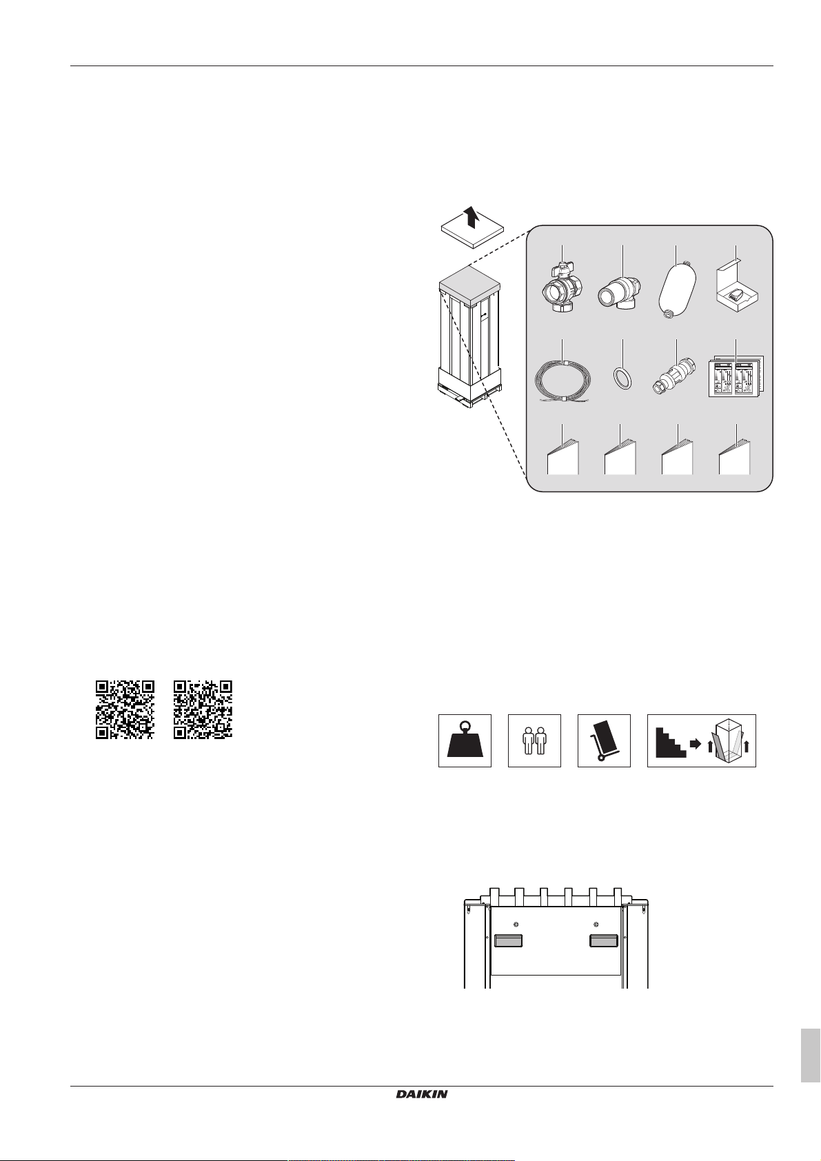
>200
kg
▪ Installer reference guide:
▪ Preparation of the installation, good practices, reference
data,…
▪ Format: Digital files on http://www.daikineurope.com/support-
and-manuals/product-information/
▪ Addendum book for optional equipment:
▪ Additional info about how to install optional equipment
▪ Format: Paper (in the box of the unit) + Digital files on http://
www.daikineurope.com/support-and-manuals/productinformation/
Latest revisions of the supplied documentation may be available on
the regional Daikin website or via your dealer.
The original documentation is written in English. All other languages
are translations.
Technical engineering data
▪ A subset of the latest technical data is available on the regional
Daikin website (publicly accessible).
▪ The full set of latest technical data is available on the Daikin
Business Portal (authentication required).
Online tools
In addition to the documentation set, some online tools are available
for installers.
▪ Heating Solutions Navigator
▪ Digital toolbox that offers a variety of tools to facilitate the
installation and configuration of heating systems.
▪ To access Heating Solutions Navigator, registration to the
Stand By Me platform is required. For more information, see
https://professional.standbyme.daikin.eu/.
▪ Daikin e-Care
▪ Mobile app for installers and service technicians that allows you
to register, configure and troubleshoot heating systems.
▪ The mobile app can be downloaded for iOS and Android
devices using the QR codes below. Registration to the Stand
By Me platform is required to access the app.
App Store Google Play
2 About the box
2.1 Indoor unit
2.1.1 To remove the accessories from the indoor unit
a Shut-off valve with integrated filter
b Safety valve (connection parts for mounting on top of brine
level vessel included)
c Brine level vessel
d Remote outdoor sensor (with installation manual)
e Cable for remote outdoor sensor (40m)
f O-rings (spares for hydro module shut-off valves)
g Tundish (to mount onto the pressure relief valve discharge
pipe)
h Energy label
i General safety precautions
j Addendum book for optional equipment
k Installation manual
l Operation manual
2.1.2 To handle the indoor unit
Mind the following guidelines when handling the unit:
EGSAH/X06+10UDA9W
Daikin Altherma 3 GEO
4P598591-1 – 2019.10
▪ The unit is heavy. At least 2 persons are needed to handle it.
▪ Use a trolley to transport the unit. Make sure to use a trolley with a
sufficiently long horizontal ledge, suitable for transportation of
heavy appliances.
▪ When transporting the unit, keep the unit upright.
▪ Use the handles at the back to carry the unit.
▪ Remove the hydro module when you want to carry the unit up or
down staircases. See "3.2.2To remove the hydro module from the
unit"[48] for more information.
▪ It is recommended to use lifting straps to carry the unit up or down
staircases.
Installation manual
5
3 Unit installation
d
b
a
c
e
g
f
≥300
≥650
≥
500
(mm)
50
3
2
1
5
6
4
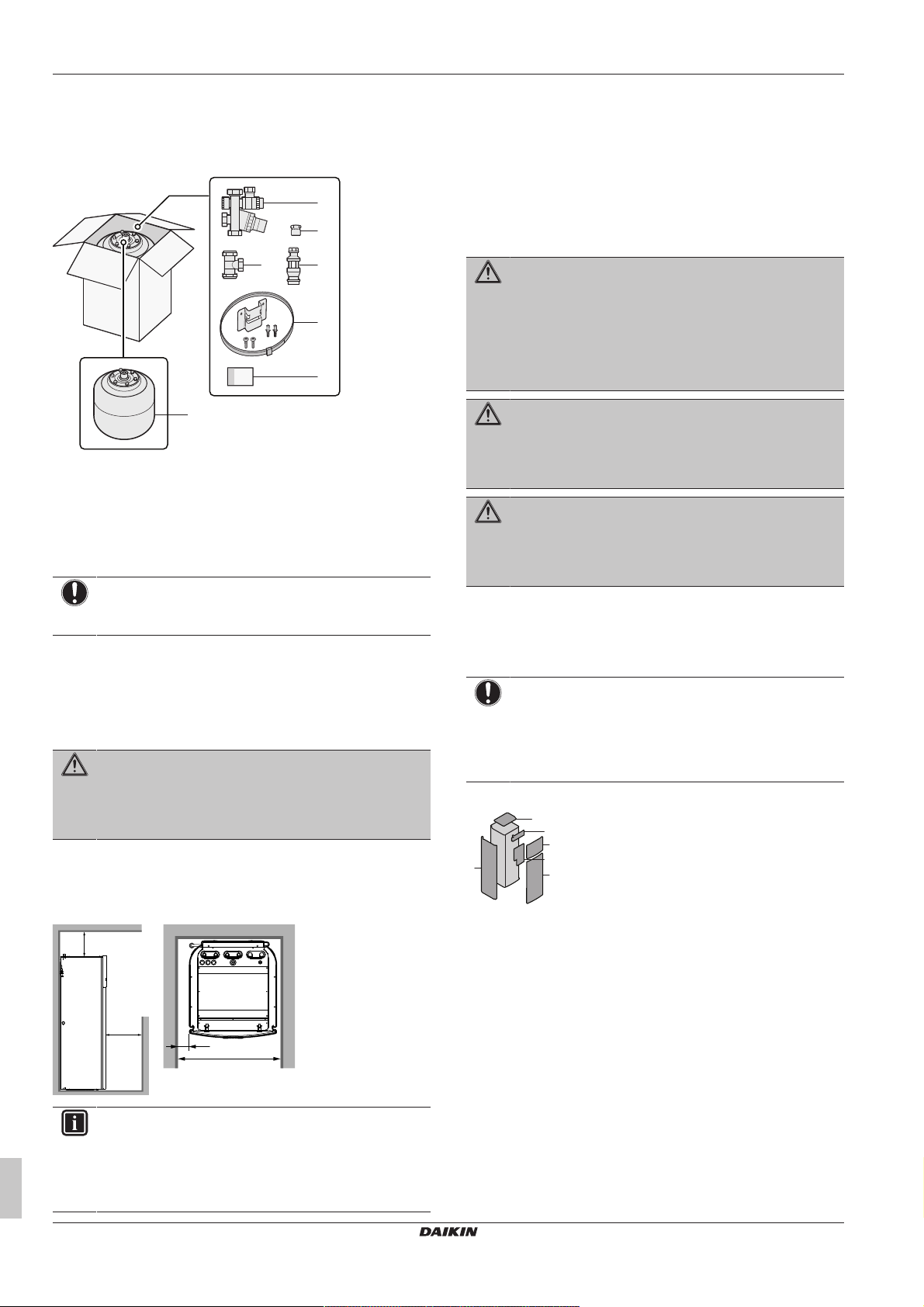
2.2 Domestic hot water tank kit
2.2.1 To remove the accessories from the domestic hot water tank kit
a Pressure reducing valve/pressure relief valve combination.
Water inlet and water outlet 22mm connection, discharge
piping connection 15mm
b Adaptor 22mm×3/4" Female BSP
c T-piece 22mm×22mm×22mm
d Tundish 15mm inlet, 22mm outlet
e Wall mounting set for expansion vessel
f Instruction sheet
g Expansion vessel of 18L – 3/4" Male BSP
NOTICE
All piping MUST be installed according to section G3 of the
Building Regulations.
▪ The indoor unit is designed for indoor installation only and for
ambient temperatures ranging from 5~35°C.
Special requirements for R32
The indoor unit contains an internal refrigerant circuit (R32), but you
do NOT have to do any refrigerant field piping or refrigerant
charging.
The total refrigerant charge in the system is ≤1.842 kg, so the
system is NOT subjected to any requirements to the installation
room. However, mind the following requirements and precautions:
WARNING
▪ Do NOT pierce or burn.
▪ Do NOT use means to accelerate the defrosting
process or to clean the equipment, other than those
recommended by the manufacturer.
▪ Be aware that R32 refrigerant does NOT contain an
odour.
WARNING
The appliance shall be stored so as to prevent mechanical
damage and in a well-ventilated room without continuously
operating ignition sources (example: open flames, an
operating gas appliance or an operating electric heater).
WARNING
Make sure installation, servicing, maintenance and repair
comply with instructions from Daikin and with applicable
legislation (for example national gas regulation) and are
executed only by authorised persons.
3.2 Opening and closing the unit
3 Unit installation
3.1 Preparing the installation site
WARNING
The appliance shall be stored in a room without
continuously operating ignition sources (example: open
flames, an operating gas appliance or an operating electric
heater).
3.1.1 Installation site requirements of the indoor unit
▪ Mind the following spacing installation guidelines:
3.2.1 To open the indoor unit
NOTICE
For a standard installation, it is usually NOT required to
open the unit. Opening the unit or any of the switch boxes
is ONLY required when you want to install extra option kits.
For more information, see the installation manual of the
specific option kit, or below.
Overview
1 Top panel
2 User interface panel
3 Front panel
4 Left side panel
5 Installer switch box cover
6 Main switch box cover
Open
1 Remove the top panel.
INFORMATION
If you have limited installation space and need to install the
option kit EKGSPOWCAB (=power cable for split power
supply), remove the left side panel before installing the unit
in its final position. See "3.2.1 To open the indoor
unit"[46].
Installation manual
6
EGSAH/X06+10UDA9W
Daikin Altherma 3 GEO
4P598591-1 – 2019.10
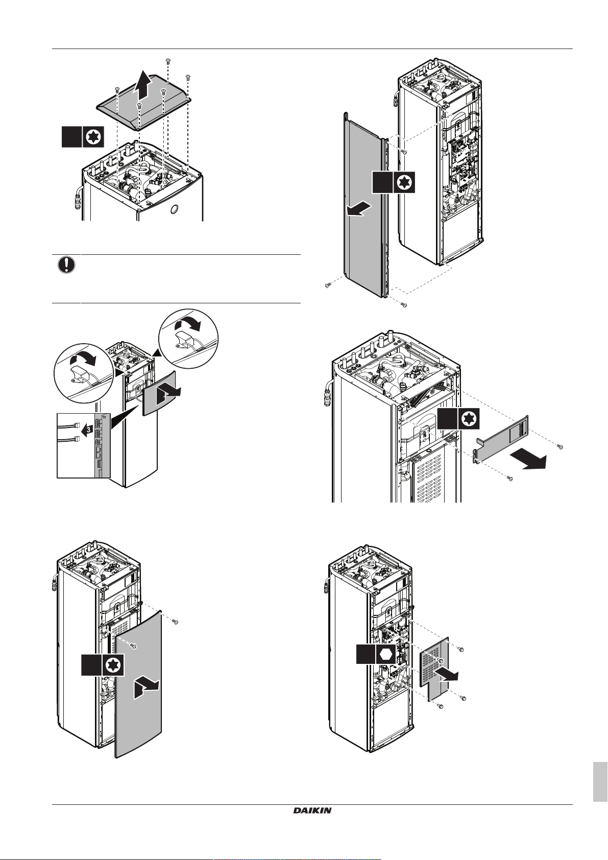
5×
T25
2 Remove the user interface panel. Open the hinges at the top
1
1
2
2×
T25
3×
T25
2×
T25
4×
and slide the user interface panel upwards.
NOTICE
If you remove the user interface panel, also disconnect the
cables from the back of the user interface panel to prevent
damage.
3 Unit installation
5 Open the installer switch box as follows:
3 If necessary, remove the front panel. This is, for example,
necessary when you want to remove the hydro module from the
unit. See "3.2.2 To remove the hydro module from the
unit"[48] for more information.
4 In case you want to install the option kit EKGSPOWCAB
(=power cable for split power supply), also remove the left side
panel. Also see "5.3To connect the main power supply"[415].
6 In case you have to install additional options that require access
to the main switch box, remove the main switch box cover as
follows:
EGSAH/X06+10UDA9W
Daikin Altherma 3 GEO
4P598591-1 – 2019.10
Installation manual
7
3 Unit installation
2
1
4×
4×
T25
X22Y
X11YB
X803YA
X1YA
5×
T25
1×
T25
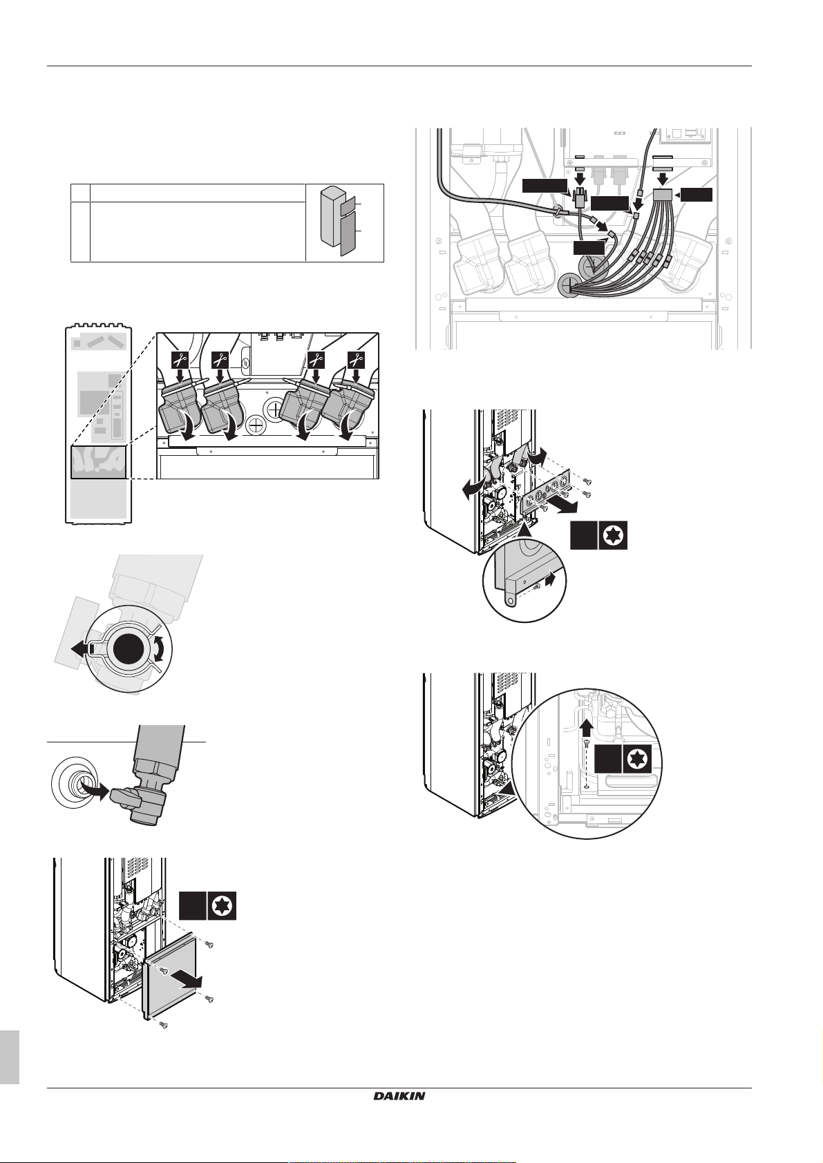
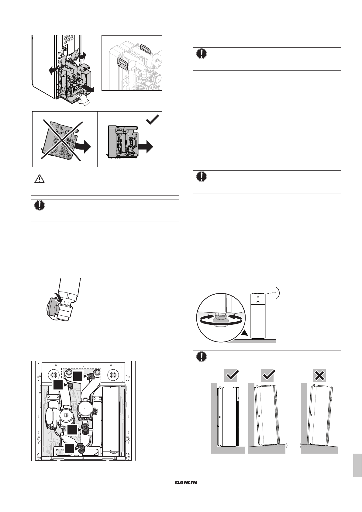
3.2.2 To remove the hydro module from the unit
Removing the hydro module is only required for easier transportation
of the unit or for servicing. The removal of the module will
significantly reduce the weight of the unit. This makes the unit easier
to handle and carry.
1 Open the following (see "3.2.1To open the indoor unit"[46]):
1 User interface panel
2 Front panel
2 Remove the insulation from the shut-off valves by cutting the
cable ties.
6 Unlink the connectors that run from the hydro module to the
main switch box or other locations. Route the wires through the
grommets of the upper hydro module cover.
7 Remove the upper hydro module cover. You can lift up the
uncoupled piping to access the screws more easily, and to take
off the cover itself.
3 Remove the clips that lock the valves in place.
4 Uncouple the piping.
5 Remove the lower hydro module cover.
8 Remove the screw that fixes the hydro module to the bottom
plate.
9 Lift the uncoupled piping and use the handle on the front of the
module to carefully slide the module out of the unit. Make sure
the module remains level and does not tilt forward.
Installation manual
8
EGSAH/X06+10UDA9W
Daikin Altherma 3 GEO
4P598591-1 – 2019.10
3 Unit installation
4×
d
a
b
c
≤1°
0°
1° 1°
c Brine air purge valve
d Water air purge valve
NOTICE
Ensure that no brine or water can fall into the switch box of
the hydro module.
5 Perform the remaining steps as described in "3.2.2 To remove
the hydro module from the unit"[48].
3.2.3 To close the indoor unit
1 If applicable, reinstall the left side panel.
2 If applicable, reinsert the hydro module.
3 If applicable, close the cover of the main switch box and
reinstall the front panel.
4 Close the cover of the installer switch box.
5 Reconnect the cables to the user interface panel.
6 Reinstall the user interface panel.
7 Reinstall the top panel.
CAUTION
The hydro module is heavy. It requires at least two persons
to carry it.
NOTICE
Make sure not to damage any insulation during the
removal process.
Removal after first installation
If the water and brine circuits have been filled before, remaining
water and brine need to be drained from the hydro module before
removal. In this case, perform the following actions:
1 Remove the insulation from the shut-off valves. (See step 2 in
"3.2.2To remove the hydro module from the unit"[48].)
2 Close the shut-off valves by turning the lever handles.
3 Remove the lower hydro module cover. (See step 5 in "3.2.2To
remove the hydro module from the unit"[48].)
4 Drain remaining water and brine from the hydro module. Open
the water and brine air purge valves at the top of the module to
speed up the draining process.
NOTICE
When closing the indoor unit cover, make sure that the
tightening torque does NOT exceed 4.1N•m.
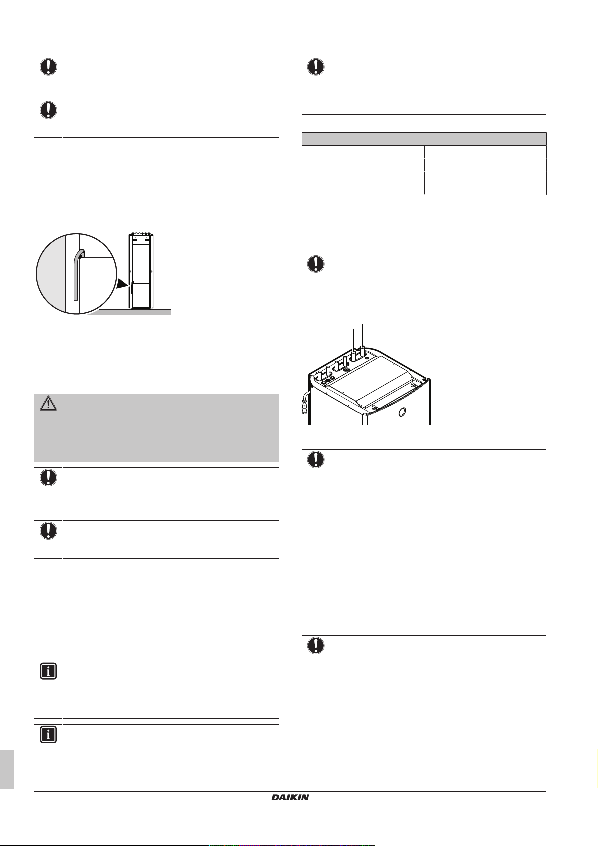
3.3 Mounting the indoor unit
3.3.1 To install the indoor unit
1 Lift the indoor unit from the pallet and place it on the floor. See
"2.1.2To handle the indoor unit"[45].
2 Connect the drain hose to the drain. See "3.3.2To connect the
drain hose to the drain"[410].
3 Slide the unit into position.
4 Adjust the height of the 4 levelling feet of the outer frame to
compensate for floor irregularities. The maximum allowed
deviation is 1°.
NOTICE
Do NOT tilt the unit forwards:
a Water drain valve
b Brine drain valve
EGSAH/X06+10UDA9W
Daikin Altherma 3 GEO
4P598591-1 – 2019.10
Installation manual
9
4 Piping installation
a
b
NOTICE
To avoid structural damage on unit, ONLY move the unit
when levelling feet are at their lowest position.
NOTICE
For optimum sound reduction, carefully check if there is no
gap between the bottom frame and the floor.
3.3.2 To connect the drain hose to the drain
Condensate can form inside the unit during cooling operation or with
low brine temperatures. The top and backup heater drain pans are
connected to a drain hose inside the unit. You must connect the
drain hose to an appropriate drain according to the applicable
legislation. The drain hose is routed through the rear panel, towards
the right side of the unit.
4 Piping installation
NOTICE
When circulation in each space heating/cooling loop is
controlled by remotely controlled valves, it is important that
the minimum water volume is guaranteed, even if all of the
valves are closed.
Minimum flow rate
Minimum required flow rate
Heat pump operation No minimum required flow
Cooling operation 10l/min
Backup heater operation No minimum required flow during
heating
4.2 Connecting the brine piping
4.2.1 To connect the brine piping
NOTICE
Do NOT use excessive force when connecting the field
piping and make sure the piping is aligned properly.
Deformation of the piping can cause malfunctioning of the
unit.
4.1 Preparing piping
WARNING
It is the responsibility of the installer to ensure the
compatibility of field piping with the used anti-freeze fluid in
the brine circuit. Do NOT use Zn-coated piping, as this
may lead to excessive corrosion. See also "4.2.4To fill the
brine circuit"[411].
NOTICE
In case of plastic pipes, make sure they are fully oxygen
diffusion tight according to DIN 4726. The diffusion of
oxygen into the piping can lead to excessive corrosion.
NOTICE
All piping MUST be installed according to section G3 of the
Building Regulations.
4.1.1 To check the water volume and flow rate of the space heating circuit and brine circuit
Minimum water volume
Check that the total water volume per circuit in the installation is
minimum 20litre, the internal water volume of the indoor unit NOT
included.
INFORMATION
If a minimum heating load of 1kW can be guaranteed and
setting [4.B] Space heating/cooling > Overshoot
(overview field setting [9‑04]) is 4°C, the minimum water
volume can be lowered to 10litre.
a Brine OUT (Ø28mm)
b Brine IN (Ø28mm)
NOTICE
To facilitate service and maintenance, it is recommended
to install shut-off valves as close as possible to the inlet
and outlet of the unit.
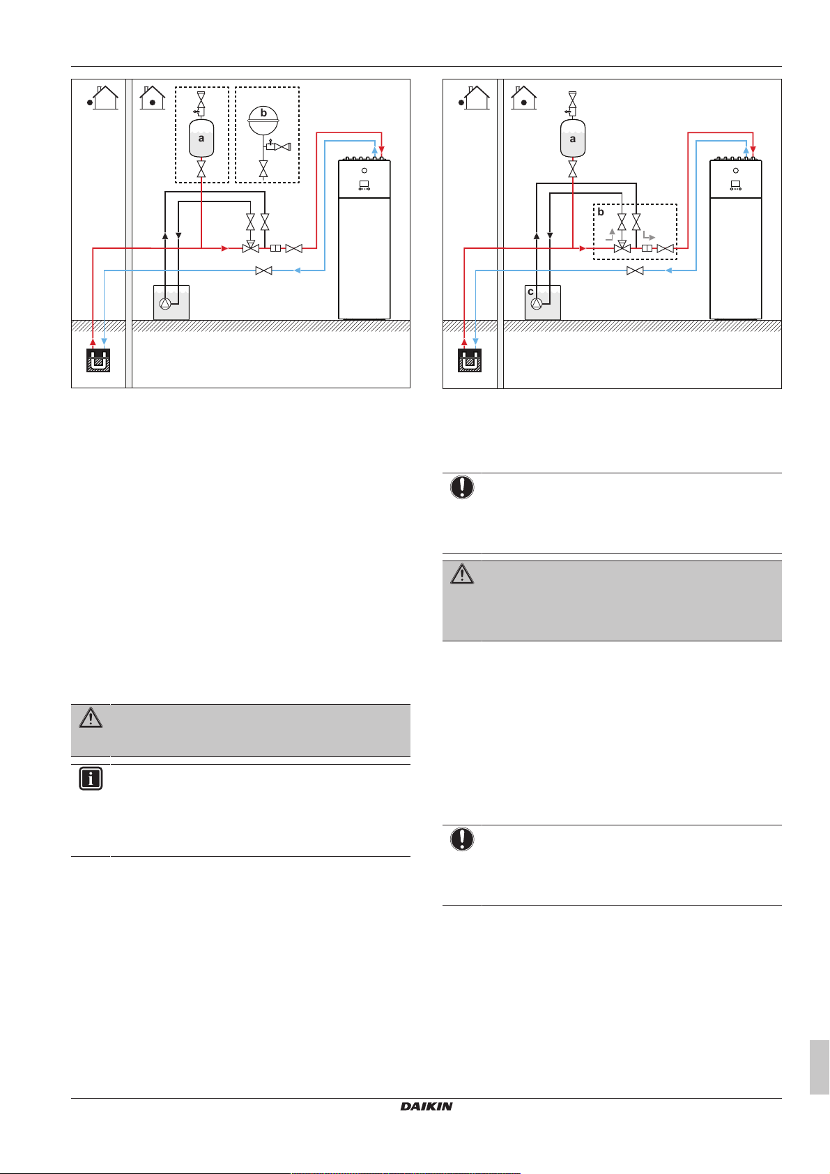
4.2.2 To connect the brine level vessel
The brine level vessel (delivered as accessory) must be installed on
the brine side of the heat pump system. A safety valve is included
with the vessel. The vessel serves as a visual indicator of the brine
level of the system. Air trapped in the system is collected by the
vessel, causing the level of brine in the vessel to decrease.
1 Install the brine level vessel as the highest point in the brine
circuit on the entering brine piping.
2 Mount the included safety valve on top of the vessel.
3 Install a shut-off valve (field supplied) below the vessel.
NOTICE
If it is not possible to install the brine level vessel as the
highest point in the circuit, install an expansion vessel (field
supply) and install the safety valve in front of the expansion
vessel. Failure to observe this instruction may result in
malfunctioning of the unit.
INFORMATION
In critical processes, or in rooms with a high heat load,
extra water might be required.
Installation manual
10
EGSAH/X06+10UDA9W
Daikin Altherma 3 GEO
4P598591-1 – 2019.10
4 Piping installation
b
a
a
c
b
a Brine level vessel (accessory)
b Expansion vessel (field supply, in case brine level vessel
cannot be installed as the highest point)
If the level of brine in the vessel is lower than 1/3, fill the vessel with
brine:
4 Close the shut-off valve below the vessel.
5 Remove the safety valve on top of the vessel.
6 Top up the vessel with brine until it is approximately 2/3 filled.
7 Reconnect the safety valve.
8 Open the shut-off valve below the vessel.
4.2.3 To connect the brine filling kit
A brine filling kit (field supply or option kit KGSFILL2) can be used to
flush, fill and drain the brine circuit of the system.
For installation instructions, see the installation manual of the brine
filling kit.
4.2.4 To fill the brine circuit
WARNING
Before, during and after filling carefully check the brine
circuit for leakage.
INFORMATION
The materials used in the brine circuit of the unit are
chemically resistant to the following anti-freeze fluids:
▪ 40 mass% propylene glycol
▪ 29 mass% ethanol
1 Install the brine filling kit. See "4.2.3To connect the brine filling
kit"[411].
2 Connect a field supplied brine filling system to the 3-way valve.
3 Position the 3‑way valve correctly.
a Brine level vessel (accessory)
b Brine filling kit (field supply or option kit KGSFILL2)
c Brine filling system (field supply)
4 Fill the circuit with brine until a pressure of ±2.0bar (=200kPa).
5 Return the 3‑way valve to its original position.
NOTICE
A field supplied filling kit may come without a filter that
protects components in the brine circuit. In this case, it is
the responsibility of the installer to install a filter on the
brine side of the system.
WARNING
Temperature of the fluid running through the evaporator
can become negative. It MUST be protected against
freezing. For more information, see setting [A‑04] in
"6.4.4Brine freezing temperature"[434].
4.2.5 To insulate the brine piping
The piping in the complete brine circuit MUST be insulated to
prevent reduction of the heating capacity.
Consider that the brine circuit piping inside the house can/will
condensate. Foresee adequate insulation for these pipes.
4.3 Connecting the water piping
4.3.1 To connect the water piping
NOTICE
Do NOT use excessive force when connecting the field
piping and make sure the piping is aligned properly.
Deformation of the piping can cause malfunctioning of the
unit.
1 Install the shut off-valve with integrated filter (delivered as
accessory) at the space heating/cooling water inlet.
2 Connect the space heating/cooling in pipe to the shut-off valve
and the space heating/cooling out pipe to the unit.
3 Connect the domestic hot water in and out pipes to the indoor
unit. It is obligatory to use the accessory G3 kit EKUHWG3D to
comply with UK legislation. See "4.3.2 To connect the water
piping for domestic hot water"[412].
EGSAH/X06+10UDA9W
Daikin Altherma 3 GEO
4P598591-1 – 2019.10
Installation manual
11
4 Piping installation
a
b
c
d
b
a
e
e
b
d
c
a Space heating/cooling water OUT (Ø22mm)
b Space heating/cooling water IN (Ø22mm) and shut-off
valve with integrated filter (accessory)
c Domestic hot water: hot water OUT (Ø22mm)
d Domestic hot water: cold water IN (Ø22mm)
NOTICE
It is recommended to install shut-off valves to cold water in
and hot water out connections. Shut-off valves are field
supplied.
NOTICE
About the shut-off valve with integrated filter (delivered as
accessory):
▪ The installation of the valve at the water inlet is
mandatory.
▪ Mind the flow direction of the valve.
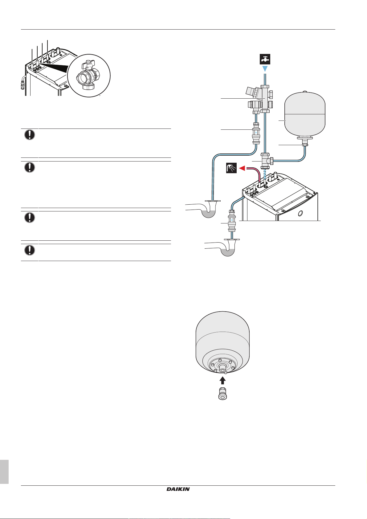
4.3.2 To connect the water piping for domestic hot water
NOTICE
Expansion vessel. An expansion vessel (field supply)
MUST be installed on the entering piping before the water
pump within 10m of the unit.
NOTICE
Install air purge valves at all local high points.
a Pressure reducing valve/pressure relief valve combination.
Water inlet and water outlet 22mm connection, discharge
piping connection 15mm
b Adaptor 22mm×3/4" Female BSP
c T-piece 22mm×22mm×22mm
d Expansion vessel of 18L – 3/4" Male BSP
e Tundish 15mm inlet, 22mm outlet
1 Pre-assemble the adaptor and expansion vessel so that the
expansion vessel is ready for installation.
Installation manual
12
2 Mount the expansion vessel to the wall.
EGSAH/X06+10UDA9W
Daikin Altherma 3 GEO
4P598591-1 – 2019.10
1 2
3 Fit the T-piece (part of the kit) to the domestic hot water cold
≤600 mm
≥300 mm
a
D1
D2
c
b
d
water IN pipe of the unit.
4 Connect the pressure reducing valve/pressure relief valve
combination (part of the kit) to the T-piece with a length of
copper tube Ø22mm (field supply).
5 Connect the expansion vessel to the T-piece with a length of
copper tube Ø22mm (field supply).
6 Connect the pressure reducing valve/pressure relief valve
combination to the water mains inlet.
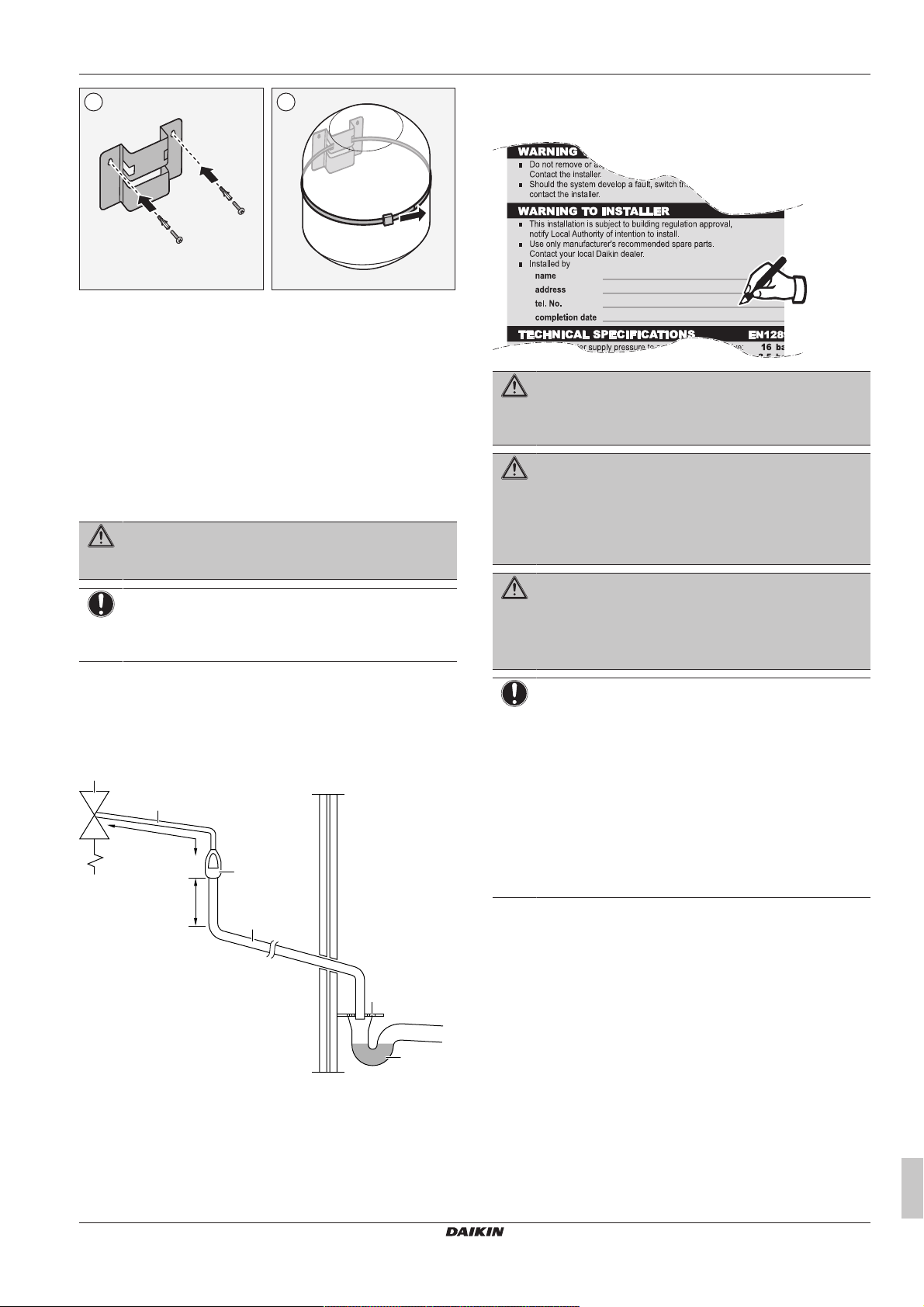
7 Install the tundish (part of the kit) in a vertical position within a
maximum of 600mm away from the pressure reducing valve/
pressure relief valve combination.
WARNING
Install the tundish away from any electrical device.
Possible consequence: Electric shock or fire.
NOTICE
To ensure a free water flow through the discharge pipe,
manually operate the pressure relief valve by turning its
knob left.
8 Connect the 2 tundishes (1 from the pressure relief valve of the
domestic hot water tank, and 1 from the pressure relief valve of
the domestic hot water tank kit) to an appropriate drain
according to the applicable legislation. The following example
shows discharge below fixed grating (Building Regulation G3
section 3.61 gives alternative points of discharge):
4 Piping installation
9 After completing the installation, the installer has to fill out the
warning label on the tank with indelible ink. The warning label
can be found on the unit top plate.
WARNING
The discharge pipes from the pressure relief valves MUST
terminate in a safe and visible position without forming any
risk to persons in the vicinity.
WARNING
▪ Discharge piping, tundish, drain valves, etc. must be
positioned away from any electrical components.
▪ The discharge pipe away from the tundish must
terminate in a safe, visible position without forming any
risk to persons in the vicinity.
WARNING
▪ Do not install any valves between the domestic hot
water tank and relief valves/expansion vessel.
▪ Do not install shut-off valves between the expansion
relief valve and the domestic hot water tank.
NOTICE
▪ All pipework and fittings must be flushed free of flux
and debris prior to installing the domestic hot water
tank kit. Failure to do this may cause irreparable
damage to the tank kit controls. Flush the system by
opening the hot water tap.
▪ The tundish pipework must be a 22mm metal pipe with
a minimal vertical length of 300mm below the tundish
before any elbows or bends in the pipework. All
pipework must have a continuous fall of 1 in 200
thereafter. Maximum permitted (equivalent) length of
22 mm pipework is 9 m. Each bend or elbow is
equivalent to 0.8m of pipework.
EGSAH/X06+10UDA9W
Daikin Altherma 3 GEO
4P598591-1 – 2019.10
a Safety device (pressure and temperature relief valve of
domestic hot water tank; pressure relief valve of domestic
hot water tank kit)
b Tundish
c Fixed grating
d Trapped gully
D1 Metal discharge pipe from safety device to tundish
D2 Discharge pipe from tundish, with continuous fall. See
Building Regulation G3 section 3.56, Table 03 and worked
example.
4.3.3 To connect the recirculation piping
Prerequisite: Only required if you need recirculation in your system.
1 Remove the top panel from the unit, see "3.2.1To open the
indoor unit"[46].
2 Cut out the rubber grommet on top of the unit, and remove the
stop. The recirculation connector is located below the space
heating/cooling water outlet pipe.
3 Route the recirculation piping through the grommet and connect
it to the recirculation connector.
Installation manual
13
5 Electrical installation
C1
1N~, 50 Hz,
230 V AC
C1
C5
1N~, 50 Hz,
230 V AC
1N~, 50 Hz,
230 V AC
4 Reattach the top panel.
4.3.4 To fill the space heating circuit
To fill the space heating circuit, use a field supply filling kit. Make
sure you comply with the applicable legislation.
NOTICE
▪ Air in the water circuit can cause malfunctioning of the
backup heater. During filling, it may not be possible to
remove all the air from the circuit. Remaining air will be
removed through the automatic air purge valves during
the initial operating hours of the system. Additional
filling with water afterwards may be required.
▪ To purge the system, use the special function as
described in the chapter "7 Commissioning" [4 36].
This function should be used to purge the heat
exchanger coil of the domestic hot water tank.
5 Electrical installation
DANGER: RISK OF ELECTROCUTION
WARNING
ALWAYS use multicore cable for power supply cables.
CAUTION
Do NOT push or place redundant cable length in the unit.
NOTICE
The distance between the high voltage and low voltage
cables should be at least 50mm.
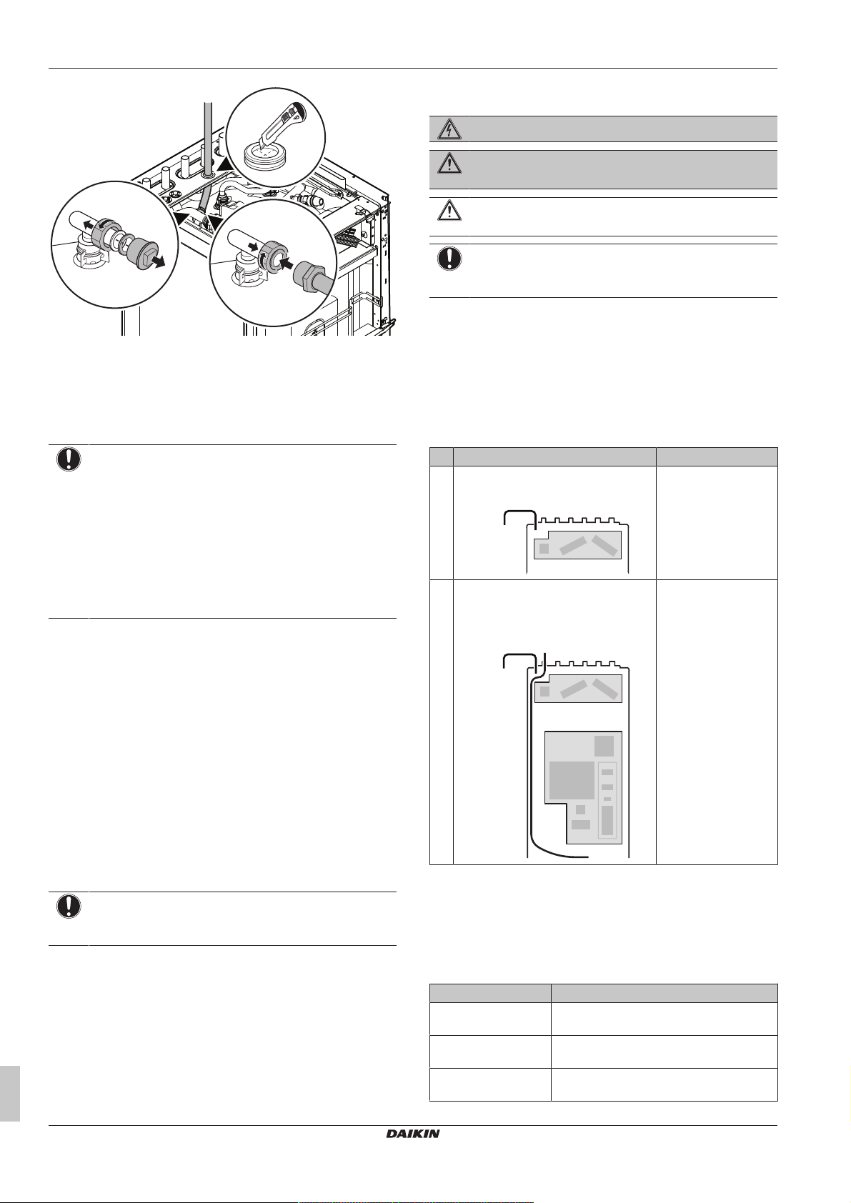
5.1 About electrical compliance
For the models EGSAH/X06+10DA9W(G), the following statement…
Equipment complying with EN/IEC 61000‑3‑12 (European/
International Technical Standard setting the limits for harmonic
currents produced by equipment connected to public low-voltage
systems with input current >16A and ≤75A per phase.).
…is valid in the following cases:
# Power supply
1 Combined power supply
(1N~, 50Hz, 230VAC)
2 Split power supply
(2×(1N~, 50Hz, 230VAC))
(a)
Operation
Normal or emergency
Emergency
(b)
4.3.5 To fill the domestic hot water tank
1 Open every hot water tap in turn to purge air from the system
pipe work.
2 Open the cold water supply valve.
3 Close all water taps after all air is purged.
4 Check for water leaks.
5 Manually operate the field-installed pressure relief valve to
ensure a free water flow through the discharge pipe.
4.3.6 To check for water leaks
Before insulating the water piping, it is important to detect water
leaks, in particular small leaks. Small leaks can easily be overseen,
but can cause damage to the unit and surroundings over a longer
period of time.
NOTICE
After water piping installation, check all connections for
leaks.
4.3.7 To insulate the water piping
The piping in the complete water circuit MUST be insulated to
prevent reduction of the heating capacity.
Consider that the space heating piping can condensate during
cooling operation. Foresee adequate insulation for these pipes.
(a) For details of C1 and C5, see "5.3To connect the main
power supply"[415].
(b) Normal operation: backup heater = maximum 3kW
Emergency operation: backup heater = maximum 6kW
5.2 Overview of electrical connections for external and internal actuators
Item Description
Power supply See "5.3To connect the main power
supply"[415].
Remote outdoor
sensor
Shut-off valve See "5.5To connect the shut-off
See "5.4To connect the remote outdoor
sensor"[418].
valve"[418].
Installation manual
14
EGSAH/X06+10UDA9W
Daikin Altherma 3 GEO
4P598591-1 – 2019.10
 Loading...