

Daikin DCC180, DCC240, DCC300 Installation Instructions Manual
INSTALLATION INSTRUCTIONS
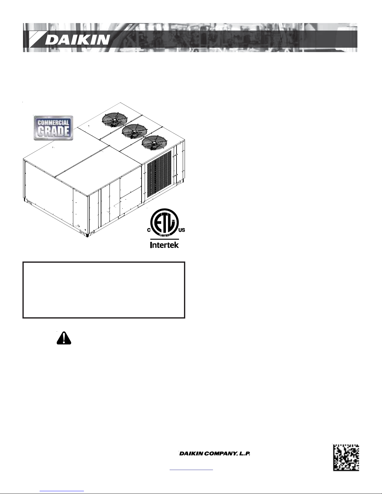
DCC SERIES
LIGHT COMMERCIAL PACKAGED HEATING AND COOLING UNIT
15 to 25 TON
Index
Replacement Parts................................................................ 2
Safety Instructions................................................................ 2
General Information ............................................................. 2
Unit Location ........................................................................ 3
Clearances ............................................................................ 5
Roof Curb Post-Installation Checks ....................................... 6
Roof Top Duct Connections................................................... 6
Rigging Details ...................................................................... 6
NOTE: 15 & 20 ton model shown in picture.
25 ton model has 2 fans.
ATTENTION INSTALLING PERSONNEL:
Prior to installation, thoroughly familiarize yourself with
this Installation Manual. Observe all safety warnings. During installation or repair, caution is to be observed.
It is your responsibility to install the product safely and to
educate the customer on its safe use.
RECOGNIZE THIS SYMBOL
AS A SAFETY PRECAUTION.
These installation instructions cover the outdoor installation of
single package heating and cooling units. See the Specification
Sheet applicable to your model for information regarding
accessories.
*NOTE: Please contact your distributor or our website for the
applicable Specification Sheet referred to in this manual.
Electrical Wiring.................................................................... 7
Circulating Air and Filters...................................................... 9
Condensate Drain Connection .............................................. 9
Startup, Adjustments, and Checks ...................................... 1 0
Airflow Adjustments........................................................... 11
Motor Sheave Adjustments ................................................ 12
Maintenance ...................................................................... 13
Appendix A Blower Performance Data................................ 15
Belt Drive - Standard ..................................................... 15
Belt Drive - High Static ................................................... 16
Appendix A Economizer Pressure Drop................................17
Appendix B Electrical Data.................................................. 18
Appendix C Unit Dimensions............................................... 21
Appendix D Wiring Diagrams .............................................. 22
Wiring Diagrams for Models With DDC Controls.................. 29
Start-up Checklist................................................................ 34
Our continuing commitment to quality products may mean a change in specifications without notice.
IOD-1003H
6/2017
© 2013, 2015-2017
5151 San Felipe St., Suite 500, Houston, TX 77056
www.daikinac.com
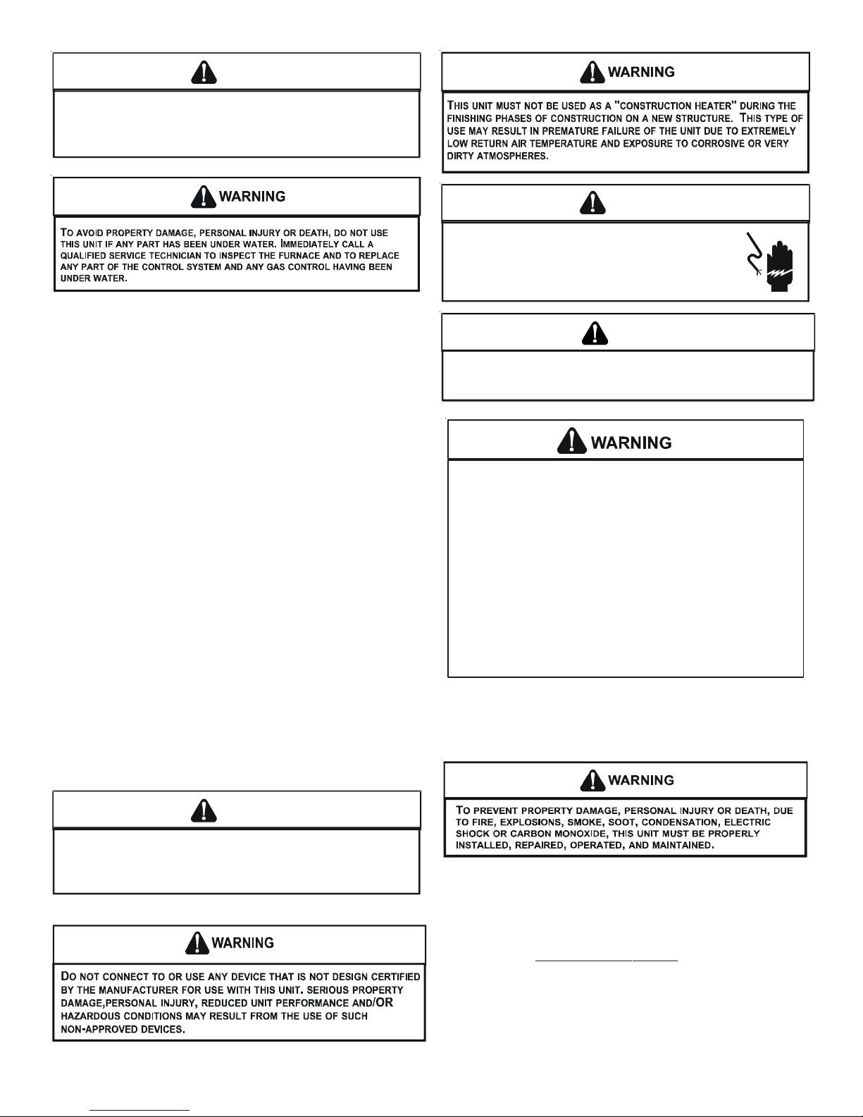
WARNING
T
HIS PRODUCT CONTAINS OR PRODUCES A CHEMICAL OR CHEMICALS
WHICH MAY CAUSE SERIOUS ILLNESS OR DEATH AND WHICH ARE
KNOWN TO THE STATE OF CALIFORNIA TO CAUSE CANCER, BIRTH
DEFECTS OR OTHER REPRODUCTIVE HARM
.
WARNING
HIGH V OLTAGE!
ISCONNECT ALL POWER BEFORE SERVICING OR
D
INSTALLING THIS UNIT
BE PRESENT
DAMAGE, PERSONAL INJURY OR DEATH
. F
. M
AILURE TO DO SO MAY CAUSE PROPERTY
ULTIPLE POWER SOURCES MAY
.
REPLACEMENT PARTS
ORDERING PARTS
When reporting shortages or damages, or ordering repair
parts, give the complete unit model and serial numbers as
stamped on the unit’s nameplate.
Replacement parts for this appliance are available through
your contractor or local distributor. For the location of your
nearest distributor, consult the white business pages, the
yellow page section of the local telephone book or contact:
EQUIPMENT SUPPORT
DAIKIN NORTH AMERICA LLC
19001 KERMIER ROAD
WALLER, TEXAS 77484
855-770-5678
SAFETY INSTRUCTIONS
TO THE INSTALLER
Before installing this unit, please read this manual to
familiarize yourself on the specific items which must be
adhered to, including maximum external static pressure to
unit, air temperature rise and minimum or maximum CFM.
Keep this literature in a safe place for future reference.
WARN ING
TO
PREVENT THE RISK OF PROPERT Y DAMAGE, PERSONAL INJURY, OR DEATH
DO NOT STORE COMBUSTIBLE MATERIALS OR USE GASOLINE OR OTHER
FLAMMABLE LIQUIDS OR VAPORS IN THE VICINITY OF THIS APPLIANCE
O
NLY PERSONNEL THAT HAVE BEEN TRAINED TO INSTALL, ADJUST, SERVICE OR
REPAIR (HEREINAFTER
MANUAL SHOULD SERVICE THE EQUIPMENT
BE RESPONSIBLE FOR ANY INJURY OR PROPERTY DAMAGE ARISING FROM
IMPROPER SERVICE OR SERVICE PROCEDURES
ASSUME RESPONSIBILITY FOR ANY INJURY OR PROPERTY DAMAGE WHICH MAY
RESULT
. IN
LICENSES TO SERVICE THE EQUIPMENT SPECIFIED IN THIS MANUAL, ONLY
LICENSED PERSONNEL SHOULD SERVICE THE EQUIPMENT
INSTALLATION, ADJUSTMENT, SERVICING OR REPAIR OF THE EQUIPMENT
SPECIFIED IN THIS MANUAL, OR ATTEMPTING TO INSTALL, ADJUST, SERVICE OR
REPAIR THE EQUIPMENT SPECIFIED IN THIS MANUAL WITHOUT PROPER
TRAINING MAY RESULT IN PRODUCT DAMAGE, PROPERTY DAMAGE, PERSONAL
INJURY OR DEATH
, “
SERVICE
”)
THE EQUIPMENT SPECIFIED IN THIS
. THE
MANUFACTURER WILL NOT
. IF
YOU SERVICE THIS UNIT, YOU
ADDITION, IN JURISDICTIONS THAT REQUIRE ONE OR MORE
. I
MPROPER
.
.
GENERAL INFORMA TION
For complete information and installation instructions for
models with DDC controls, see manual DK-DDC-TGD-XXX
,
CAUTION
S
HEET METAL PARTS, SCREWS, CLIPS AND SIMILAR ITEMS INHERENTLY
HAVE SHARP EDGES, AND IT IS NECESSARY THAT THE INSTALLER AND
SERVICE PERSONNEL EXERCISE CAUTION
.
This unit is approved for outdoor installation ONLY . Rate d perf ormance is achieved after 7 2 hours of operation. Rated performance
is delivered at the specified airflow. See outdoor unit specification sheet for split system models or product specification sheet
for packaged and light commercial models. Specification sheets
can be found at www.daikincomfort.com for Daikin brand products. Within the website, please select the residential or commercial products menu and then select the submenu for the type
of product to be installed, such as air conditioner s or heat pumps,
to access a list of product pages that each contain links to that
model’s specification sheet.
2
To assure that your unit operates safely and efficiently, it must be
installed, operated, and maintained in accordance with these installation and operating instructions, all local building codes and
ordinances.
EPA REGULATIONS
IMPORTANT: THE UNITED STATES ENVIRONMENTAL PROTECTION AGENCY (EPA)
HAS ISSUED VARIOUS REGULATIONS REGARDING THE INTR ODUCTION AND DISPOSAL
REFRIGERANTS IN THIS UNIT. FAILURE TO FOLLOW THESE REGULATIONS MAY
OF
THE ENVIRONMENT AND CAN LEAD TO THE IMPOSITION OF SUBSTANTIAL
HARM
. BECAUSE REGULATIONS MAY VARY DUE TO PASSAGE OF NEW LAWS, WE
FINES
A CERTIFIED TECHNICIAN PERFORM ANY WORK DONE ON THIS UNIT.
SUGGEST
SHOULD YOU HAVE ANY QUESTIONS PLEASE CONTACT THE LOCAL OFFICE OF THE
EPA.
NATIONAL CODES
This product is designed and manufactur ed to permit installation
in accordance with National Codes. It is the inst aller’ s r e sponsibility to install the product in accordance with National Codes and/
or prevailing local codes and regulations.
The heating and cooling capacities of the unit should be greater
than or equal to the design heating and cooling loads of the area
to be conditioned. The loads should be calcula te d b y an appr ov e d
method or in accordance with ASHRAE Guide or Manual J - Load
Calculations published by the Air Conditioning Contractors of
America.
4. File the claim with the following supporting documents:
a. Original Bill of Lading, certified copy , or indemnity bond.
b. Original paid freight bill or indemnity in lieu thereof.
c. Original invoice or certified copy thereof, showing trade
and other discounts or reductions.
d. Copy of the inspection report issued by carrier
representative at the time damage is reported to the
carrier. The carrier is responsible for making prompt
inspection of damage and for a thorough investigation
of each claim. The distributor or manufacturer will not
accept claims from dealers for transportation damage.
NOTE: When inspecting the unit for transportation damage,
remove all packaging materials. R ecycle or dispose of the packaging
material according to local codes.
PRE-INSTALLATION CHECKS
Carefully rea d all instructions f or the installation prior t o inst alling
unit. Ensure each step or proce dur e is under stood and an y special
considerations are taken into account before starting installation.
Assemble all tools, hardware and supplie s needed to complet e the
installation. Some items may need to be purchased locally.
UNIT LOCATION
WARN ING
Obtain from:
American National Standards Institute
25 West 43rd Street, 4th Floor
New York, NY 10036
System design and installation should also, where applicable, follow information pre sented in accept ed industry guides such as the
ASHRAE Handbooks. The manufacturer assumes no r esponsibility
for equipment installed in viola tion of an y c ode or r egula tion. The
mechanical installation of the packaged roof top units consists of
making final connections between the unit and building services;
supply and return duct connections; and drain connections (if required). The internal systems of the unit are completely factoryinstalled and tested prior to shipment.
Units are g ener ally ins t alled on a steel roof mounting curb assembly which has been shipped to the job site for installation on the
roof structure prior to the arrival of the unit. The model number
shown on the unit’s identification plate iden tifies the various components of the unit such as refrigeration tonnage, heating input
and voltage.
Carefully inspect the unit for damage. Any bolts or screws which
may have loosened in transit must be re-tightened. In the event
of damage, the receiver should:
1. Make notation on delivery receipt of any visible damage
to shipment or container.
2. Notify carrier promptly and request an inspection.
3. In case of concealed damage, c arrier should be notified as
soon as possible-preferably within 5 days.
TO
PREVENT POSSIBLE EQUIPMENT DAMAGE, PROPERTY DAMAGE
PERSONAL INJURY OR DEATH, THE FOLLOWING BULLET POINTS MUST
BE OBSERVED WHEN INSTALLING THE UNIT
.
,
IMPORTANT NOTE: Remove wood shipping rails prior to installation of the unit. See important note under Roof Curb Installation
Only.
ALL INSTALLATIONS:
I
MPORTANT NOTE: Unit should be energized 24 hours prior to
compressor start up to ensure crankcase heater has sufficiently warmed the compressors. Compressor damage may
occur if this step is not followed.
NOTE: Appliance is shipped from factory for vertical duct
application.
Proper installation of the unit ensur es tr ouble-free operation. Improper installation can result in problems ranging from noisy
operation to property or equipment damages, dangerous conditions that could result in injury or personal property damag e. Give
this booklet to the user and explain it’s provisions. The user should
retain these instructions for future reference.
• For proper operation and condensate drainage, the unit
must be mounted level.
• The flue outlet hood must be at least three f eet above any
forced air inlet located within ten feet. The economizer/
manual fresh air intake/motorized fresh air intake and
combustion air inlet mounted on the unit are not aff ected
by this restriction.
3
• Do not locate the unit in an area where the outdoor air
(i.e. combustion air for the unit) will be frequently
contaminated by compounds containing chlorine or
fluorine. Common sources of such compounds include
swimming pool chemicals and chlorine bleaches, paint
stripper , adhesives, p aints, varnishe s, sealers, wax es (which
are not yet dried) and solvents used during construction
and remodeling. Various commercial and industrial
processes may also be sources of chlorine/fluorine
compounds.
• T o avoid possible illness or death of the building occupants,
do NOT locate outside air intake device (economizer,
manual fresh air intake, motorized fresh air intake) too
close to an exhaust outlet, gas vent termination, or
plumbing vent outlet. For specific distances required,
consult local codes.
• Allow minimum clearances from the enclosure for fire
protection, proper opera tion, and service access (see Unit
Clearances). These clearances must be permanently
maintained.
• When the unit is heating, the temperature of the return
air entering the unit must be between 50°F and 100°F.
UNIT PRECAUTIONS
• Do not stand or walk on the unit.
• Do not drill holes anywhere in panels or in the base frame
of the unit (except where indicated). Unit access panels
provide structural support.
• Do not remove any access panels until unit has been
installed on roof curb or field supplied structure.
• Do not roll unit across finished roof without prior approval
of owner or architect.
• Do not skid or slide on any surface as this may damage
unit base. The unit must be store d on a flat, level surf ace.
Protect the condenser coil because it is easily damaged.
ROOF CURB INSTALLATIONS ONLY:
Before installing this unit...
IMPORTANT NOTE: This unit has been equipped with a shipping
brace under the compressor section that MUST BE REMOVED be-
fore installing the unit on a roof curb.
Please follow the instructions below to remove brace.
GROUND LEVEL INSTALLATIONS ONLY:
• When the unit is installed on the ground adjacent to the
building, a level concrete (or equal) base is recommended .
Prepare a base that is 3” larger than the package unit
footprint and a minimum of 3” thick.
• The base should also be located where no runoff of w at er
from higher ground can collect in the unit.
ROOF TOP INSTALLATIONS ONLY:
• T o a v oid possible property damage or per sonal injury, the
roof must have sufficient structural strength to carry the
weight of the unit(s) and snow or water loads as required
by local codes. Consult a structur al engineer to determine
the weight capabilities of the roof.
• The unit may be installed directly on wood floors or on
Class A, Class B, or Class C roof covering material.
• To avoid possible personal injury, a safe, flat surface for
service personnel should be provided.
• As indicated on the unit’ s data plate, a minimum clear ance
of 36” to any combustible mat erial is required on the access
side of the unit. All combustible materials must be kept
out of this area.
• This 36” clearance must also be maintained to insure
proper combustion air flow. The combustion air intake
must not be blocked f or any re ason, including blockag e by
snow.
• Adequate clearances fr om the unit to any adjacent public
walkways, adjacent buildings, building openings or
openable windows must be maintaine d in accordance with
National Codes.
CAUTION
W
HEN UNIT IS SUSPENDED, BOARDS AND SHIPPING BRACE WILL DROP WHEN
SCREWS ARE REMOVED
EMOVE FORK HOLE BRACKETS, BOARDS AND SHIPPING BRACE FROM BOTTOM
R
UNIT BEFORE PLACING UNIT ONTO CURB
OF
. TO
PREVENT PERSONAL INJURY
, STAND CLEAR.
.
1. Remove wooden struts and shipping brace per ins tallation
instructions. The struts are located in the fork holes and
are used to protect the unit from damage while lifting with
forks. The shipping brace is located underneath the unit
(under compressors). Also remove the fork hole brackets
as shown in the following figure.
2. Locate and remove the end brackets as shown in the
following graphic.
4

REMOVE 2 BRACKETS
ON EACH END TO
REMOVE
SHIPP IN G BRACE
LIFT OVER APPROXIMATE
CENTER O F UNI T
SPREADER BARS
MUST BE USED WITH
LIFTING S TRAPS THAT
ARE LESS THAN 16
FEET LONG
REMOVE 2 BRACKETS
ON EACH END TO
REMOVE
WOODEN STRUTS
• Sufficient structural support must be det ermined prior to
locating and mounting the curb and package unit.
• Ductwork must be constructed using industry guidelines.
The duct work must be placed into the roof curb before
mounting the package unit. Our full perimeter curbs
include duct connection frames to be assemble d with the
curb. Cantilevered type curbs are not available from the
factory.
• Curb insulation, cant strips, flashing and general roofing
material are furnished by the contractor.
The curbs must be supported on parallel sides by roof members.
The roof members must not penetrate supply and return duct
opening areas as damage to the unit might occur.
NOTE: The unit and curb accessories ar e designed to allow v ertical
duct installation before unit placement. Duct inst allation after unit
placement is not recommended.
CAUTION
ALL
CURBS LOOK SIMILAR
POSITIONING, CHECK JOB PLANS CAREFULLY AND VERIFY MARKINGS
ON CURB ASSEMBLY
SUPERSEDES INFORMATION SHOWN
See the manual shipped with the roof curb for assembly and installation instructions.
. TO
AVOID INCORRECT CURB
. I
NSTRUCTIONS MAY VARY IN CURB STYLES AND
.
3. Lift unit per the “Rigging Details” section of this manual,
observing all warnings and cautions. When unit is lifted,
boards and shipping brace will drop if screws have been
removed. To avoid injury, STAND CLEAR.
4. Dispose of the boards and brace appropriately.
Curb installations must c omply with local codes and should be done
in accordance with the est ablished guidelines of the National R oofing Contractors Association.
Proper unit installation requires that the roof curb be firmly and
permanently attached to the roof structure. Check for adequate
fastening method prior to setting the unit on the curb.
Full perimeter roof curbs are available from the factory and are
shipped unassembled. Field assembly, squaring, leveling and
mounting on the roof structure are the responsibility of the installing contractor. All required hardware necessary for the assembly of the sheet metal curb is included in the curb accessory.
WARN ING
TO
PREVENT POSSIBLE EQUIPMENT DAMAGE, PROPERTY DAMAGE
PERSONAL INJURY OR DEATH, THE FOLLOWING BULLET POINTS MUST
BE OBSERVED WHEN INSTALLING THE UNIT
.
,
CLEARANCES
36”; minimum
roof overhang
65”
Min.*
48” Min
.
48”
Min.
*In situations that have multiple units, a 48” minimum clearance is
required between the condenser coils.
UNIT CLEARANCES
Adequate clearance around the unit should be k ept f or safe ty , ser vice, maintenance, and proper unit operation. A total clearance
of 75” around this unit is recommended to facilitate possible blower
assembly, shaft, wheel replacement, coil, heat exchanger, electric
heat and gas furnace removal. This unit must not be installed beneath any obstruction. This unit should be installed remote from
all building exhausts to inhibit ingestion of exhaust air into the
unit’s fresh air intake.
48”
Min.*
5

Insulated
Panels
Roof Curb Installation
ROOF CURB POST -INSTALLA TION CHECK S
After installation, check the top of the curb, duct connection fr ame
and duct flanges to make sure gasket has been applied properly.
Gasket should be firmly applied to the top of the curb perimeter,
duct flanges and any exposed duct connection frame. If gasket is
loose, re-apply using strong weather resistant adhesive.
PROTRUSION
Inspect curb to ensure that none of the utility services (electric)
routed through the curb protrude above the curb.
CAUTION
CAUTION
DO
NOT LIFT UNITS TWO AT A TIME
BEEN INCLUDED IN THE UNIT BASE FRAME
72”
TO PREVENT DAMAGE TO THE UNIT
. P
ROVISIONS FOR FORKS HAVE
. M
INIMUM FORK LENGTH IS
.
Provisions for fork s have been include d in the unit base frame. No
other fork locations are approved.
WARNING
O PREVENT POSSIBLE EQUIPMENT DAMAGE, PROPERTY DAMAGE, PERSONAL
T
INJURY OR DEAT H, THE FOL LOWING BU LLET POINTS MUST BE OB SERVED
WHEN INSTALLING THE UNIT.
• Unit must be lifted by the four lifting holes located at the
base frame corners.
• Lifting c ables should be at tached to the unit with shackle s.
• The distance between the crane hook and the top of the
unit must not be less than 60”.
• Two spreader bars must span over the unit to prevent
damage to the cabinet by the lift cables. Spreader bars
must be of sufficient length so that cables do not come in
contact with the unit during transport. Remove wood
struts mounted beneath unit base frame before setting
unit on roof curb. These struts are intended to protect
unit base frame from fork lift damage. Removal is
accomplished by extracting the sheet met al r etainer s and
pulling the struts through the base of the unit. Refer to
rigging label on the unit.
Important: If using bottom discharge with roof curb, ductwork
should be attached to the curb prior to ins talling the unit. Ductwork
dimensions are shown in Roof Curb Installation Instructions.
Refer to the Roof Curb Installation Instructions for proper curb
installation. Curbing must be installed in compliance with the National Roofing Contractors Association Manual.
Lower unit carefully onto roof mounting curb. While rigging unit,
center of gravity will cause condenser end t o be lower than supply
air end.
IF
PROTRUSIONS EXIST, DO NO ATTEMPT TO SET UNIT ON CURB
ROOF TOP DUCT CONNECTIONS
Install all duct connections on the unit before placing the unit on
rooftop.
RIGGING DET AILS
WARNING
O PREVENT PROPERTY DAMAGE, THE UNIT SHOULD REMAIN IN AN UPRIGHT
T
POSITION DURING ALL RIGGING AND MOVING OPERATIONS.
LIFTING AND MOVING WHEN A CRANE IS USED, PLACE THE UNIT IN AN
ADEQUATE CABLE SLING.
T
O FACILITATE
.
SEE CAUTION BELOW
6
CAUTION
A
W
HEN UNIT IS SUSPENDED, BOARDS AND SHIPPING BRACE WILL DROP WHEN
SCREWS ARE REMOVED
R
EMOVE FORK HOLE BRACKETS, BOARDS AND SHIPPING BRACE FROM BOTTOM
OF
UNIT BEFORE PLACING UNIT ONTO CURB
. TO
PREVENT PERSONAL INJURY
, STAND CLEAR.
.
RIGGING REMOVAL
TO
PREVENT DAMAGE TO THE UNIT, DO NOT ALLOW CRANE HOOKS
AND SPREADER BARS TO REST ON THE ROOF OF THE UNIT
CAUTION
.
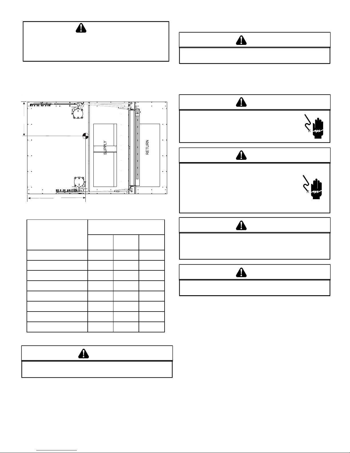
To assist in determining rigging requirements, unit weights are
shown as follows:
Y
COMPRESSOR 1
S
L
I
O
C
(lbs)
R
O
T
A
R
O
P
A
V
E
CG
COMPRESSOR 2
B
Corner Weight - A 590 644 626
Corner Weight - B 482 525 464
Corner Weight - C 492 504 501
X
CORNER & CENTER OF GRAVITY LOCATIONS
DCC Weights
DATA
15 Tons 20 Tons 25 Tons
Remove sprea der bars, lifting cable s and other rigging equipment.
ELECTRICAL WIRING
C
HIGH VOLTAGE!
ISCONNECT ALL POWER BEFORE SERVICING OR
D
INSTALLING THIS UNIT
BE PRESENT
DAMAGE, PERSONAL INJURY OR DEATH
. F
HIGH VOLTAGE!
T
O AVOID PERSONAL INJURY OR DEATH DUE TO
ELECTRICAL SHOCK, DO NOT TAMPER WITH FACTORY
WIRING
. THE
OF THESE UNITS ARE FACTORY-INSTALLED AND HAVE
BEEN THOROUGHLY TESTED PRIOR TO SHIPMENT
D
ONTACT YOUR LOCAL REPRESENTATIVE IF
C
ASSISTANCE IS REQUIRED
INTERNAL POWER AND CONTROL WIRING
. M
AILURE TO DO SO MAY CAUSE PROPERTY
WARN ING
ULTIPLE POWER SOURCES MAY
.
WARN ING
.
.
CAUTION
TO
PREVENT DAMAGE TO THE WIRING, PROTECT WIRING FROM
SHARP EDGES
LOCAL CODES AND ORDINANCES
REMOVABLE ACCESS PANELS
. F
OLLOW NATIONAL ELECTRICAL CODE AND ALL
. DO
NOT ROUTE WIRES THROUGH
.
CAUTION
Corner Weight - D 401 412 518
Un it Shipping W eight 2080 2202 2377
Un it Op era ting Wei g ht 1965 2085 2109
X (Inches) 60" 58" 64.3"
Y (Inches)
NOTE: These weights are without accessories installed.
40" 40" 41.3"
CAUTION
TO
PREVENT SEVERE DAMAGE TO THE BOTTOM OF THE UNIT, DO NOT
FORK LIFT UNIT AFTER WOOD STRUTS HAVE BEEN REMOVED
Bring condenser end of unit into alignment with the curb. With
condenser end of the unit resting on curb member and using curb
as a fulcrum, lower opposite end of the unit until entire unit is
seated on the curb. When a rectangular cantilever curb is used,
care should be taken to center the unit. Check for proper alignment and orientation of supply and return openings with duct.
C
ONDUIT AND FITTINGS MUST BE WEATHER-TIGHT TO PREVENT
WATER ENTRY INTO THE BUILDING
.
For unit protection, use a fuse or HACR circuit breaker that is in
excess of the circuit ampacity, but less than or equal to the maximum overcurrent protection device. DO NOT EXCEED THE MAXIMUM OVERCURRENT DEVICE SIZE SHOWN ON UNIT DATA PLATE.
All line voltage connections must be made through weatherproof
fittings. All exterior power supply and ground wiring must be in
approved weatherproof conduit.
The main power supply wiring to the unit and low voltage wiring
.
to accessory controls must be done in accordance with these instructions, the latest edition of the Na tional Electrical Code (ANSI/
NFPA 70), and all local codes and ordinances.
The main power supply shall be three-phase, three wir e. The unit
is factory wired for the voltage shown on the unit’s data plate.
7
NOTE: If supply voltage is 208V, all leads on primary of
g
e
transformer(s) must be moved from the 230V to the 208V tap.
Main power wiring should be sized for the minimum circuit
ampacity shown on the unit’s data plat e. Size wir es in accor dance
with the ampacity tables in Article 310 of the National Electrical
Code. If long wires are required, it may be necessary to increase
the wire size to prevent excessive voltage drop. Wires should be
sized for a maximum of 3% voltage drop.
CAUTION
O AVOID PROPERTY DAMAGE OR PERSONAL INJURY DUE TO FIRE, USE
T
ONLY COPPER COND UCTORS.
CAUTION
L
ABEL ALL WIRES PRIOR TO DISCONNECTION WHEN SERVICING
CONTROLS
DANGEROUS OPERATION
SERVICING
. W
IRING ERRORS CAN CAUSE IMPROPER AND
. V
ERIFY PROPER OPERATION AFTER
.
NOTE: A weather-tight disconnect switch, properly sized for the
unit total load, must be field or f actory installe d. An external field
supplied disconnect may be mounted on the exterior panel.
Ensure the data plate is not covered by the field-supplied
disconnect switch.
• Some disconnect switches are not fused. Protect the
power leads a t the point of distribution in accordance with
the unit’s data plate.
• The unit must be electrically grounded in accor dance with
local codes or, in the absence of local codes, with the latest
edition of the National Electrical Code (ANSI-NFPA 70). A
ground lug is provided for this purpose. Size grounding
conductor in accordance with T able 250-95 of the National
Electrical Code. Do not use the ground lug for c onnecting
a neutral conductor.
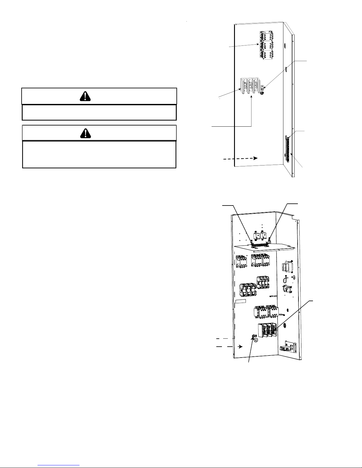
• Connect power wiring to the electrical middle contactor
within the main control box of power block, if equipped.
Line voltage connects
to middle contactor
on 460v and 575v
Gas Packs
(or power bloc k
if equipped)
Power Block
(Coolers &
230V Gas Packs
Only)
Line voltage connects
to power block on
Coolers and the 230v
Gas Packs
Field wiring enters
from this direction
POWER AND LOW VOLTAGE BLOCK LOCATIONS
Route field
control wiring
through
grommet
Ground
Lug
Low Voltage
Terminal Strip
Thermostat wirin
for all units
connect to lo w
voltage strip
Field connection
for
control wiring
at
terminal block
Field
connection
for
linevoltage
Field wiring
LOW
nters from
this direction
HIGH
Ground Lug
25 TON POWER AND LOW VOLTAGE BLOCK LOCATIONS
NOTE: Depending on the options installe d, the location of the com-
ponents may vary in some models.
8
WARN ING
F
AILURE OF UNIT DUE TO OPERATION ON IMPROPER LINE VOLTAGE
OR WITH EXCESSIVE PHASE UNBALANCE CONSTITUTES PRODUCT
ABUSE AND MAY CAUSE SEVERE DAMAGE TO THE UNIT ELECTRICAL
COMPONENTS
.
Areas Without Convenience Outlet
It is recommended that an independent 115V power source be
brought to the vicinity of the roof top unit for portable lights and
tools used by the service mechanic.
3. Use #18 AWG wire for 24V control wiring runs not
exceeding 75 feet. U se #16 A WG wire for 24V con trol wiring
runs not exceeding 125 feet. Use #14 AWG wire for 24V
control wiring runs not exceeding 200 feet. Low voltage
wiring may be National Electrical Code (NEC) Class 2 wher e
permitted by local codes.
4. Route thermostat wires from sub-base terminals to the
unit. Control wiring should enter through the duct panel
(dimple marks entrance location). Connect thermostat and
any accessory wiring to low voltage terminal block TB1 in
the main control box.
NOTE: Refer to local codes for requirements. These outlets can
also be factory installed.
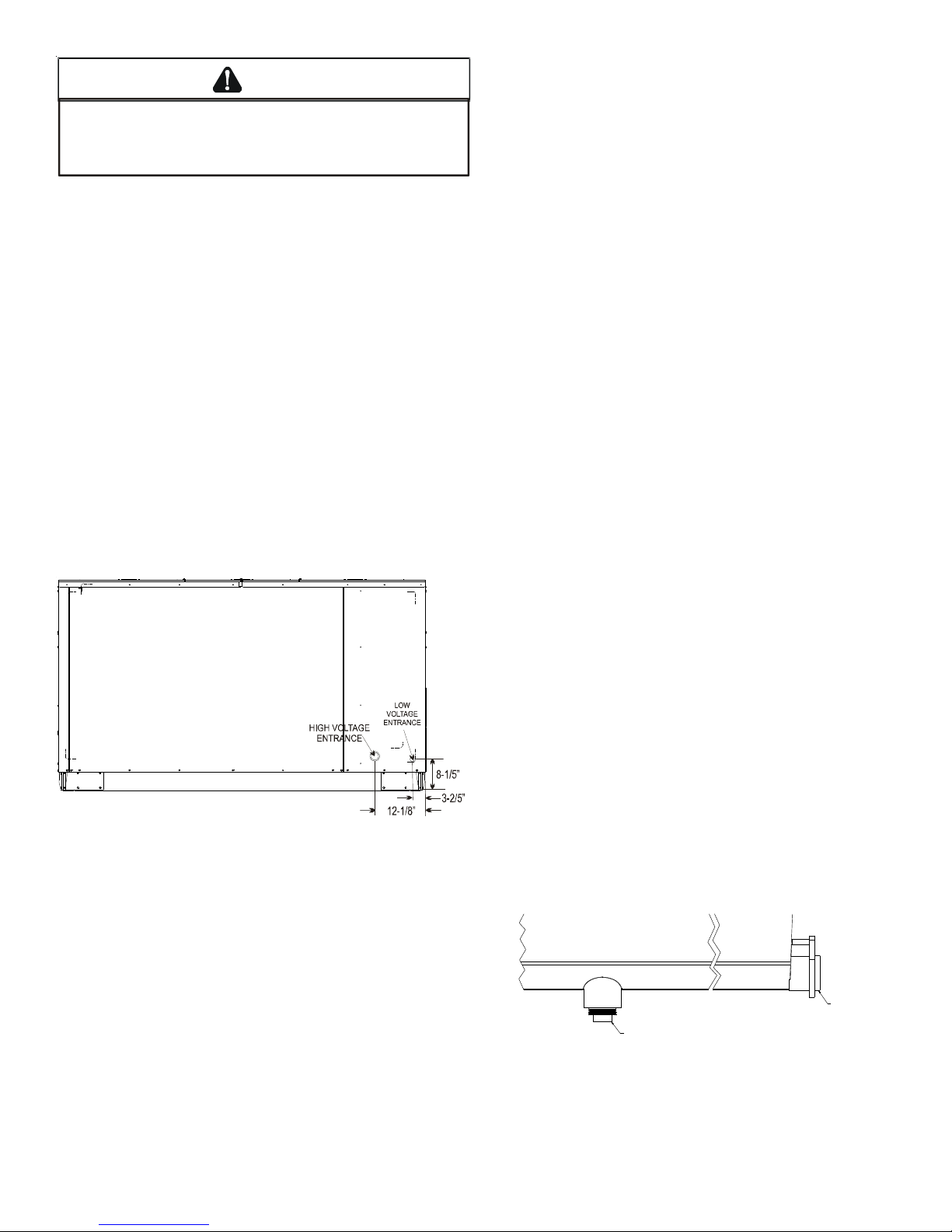
UNITS INSTALLED ON ROOF TOPS
Main power and low voltage wiring may enter the unit through
the side or through the roof curb. Install conduit connect ors at the
desired entrance locations. External connectors must be weatherproof . All hole s in the unit base mus t be seale d (including those
around conduit nuts) to prevent water leakage into building. All
required conduit and fittings are to be field supplied.
Supply voltage to roof top unit mus t not vary by more than 10% of
the value indicated on the unit’s data plate. Phase voltage unbalance must not exceed 2%. Contact your local power comp any for
correction of improper voltage or phase unbalance.
NOTE: Field-supplied conduit may need to be ins talled depending
on unit/curb configuration. Use #18 AWG solid conductor wire
whenever connecting thermostat wire s to t erminals on sub-base.
DO NOT use larger than #18 AWG wire. A transition to #18 AWG
wire may be required before entering thermostat sub-base.
NOTE: Refer to unit wiring diagrams for thermostat hookups.
CIRCULATING AIR AND FILTERS
DUCTWORK
The supply duct from the unit through a wall may be ins talled without clearance. However, minimum unit clearances must be maintained (see “Clearance s” section). The supply duct should be provided with an access panel large enough to inspect the air chamber downstream of the heat exchanger. A cover should be tightly
attached to prevent air leaks.
Ductwork dimensions are shown in the roof curb installation
manual.
If desired, supply and return duct connections to the unit may be
made with flexible connections to reduce possible unit operating
sound transmission.
ELECTRICAL ENTRANCE LOCATIONS
Unit is equipped with Single Point Power Block and Low Voltage
Block.
LOW VOLTAGE CONTROL WIRING
1. A 24V thermostat must be installed for unit operation. It
may be purchased with the unit or field -supplied.
Thermostats may be programmable or electromechanical
as required.
2. Locate thermostat or remote sensor in the conditioned
space where it will sense average temperature. Do not
locate the device where it may be directly exposed to
supply air, sunlight or other sources of heat. Follow
installation instructions packaged with the thermostat.
CONDENSA TE DRAIN CONNE CTION
CONDENSATE DRAIN CONNECTION
A 3/4” female NPT drain connection is supplied on the end of the
condensate pan, with an alternativ e c onnection on the bottom of
the pan. An external trap must be ins talled f or proper c ondensate
drainage
STANDARD
SIDEDRAIN
DRAIN PLUG
(FACT ORY-IN STAL LED)
Drain Pan (Side View)
9
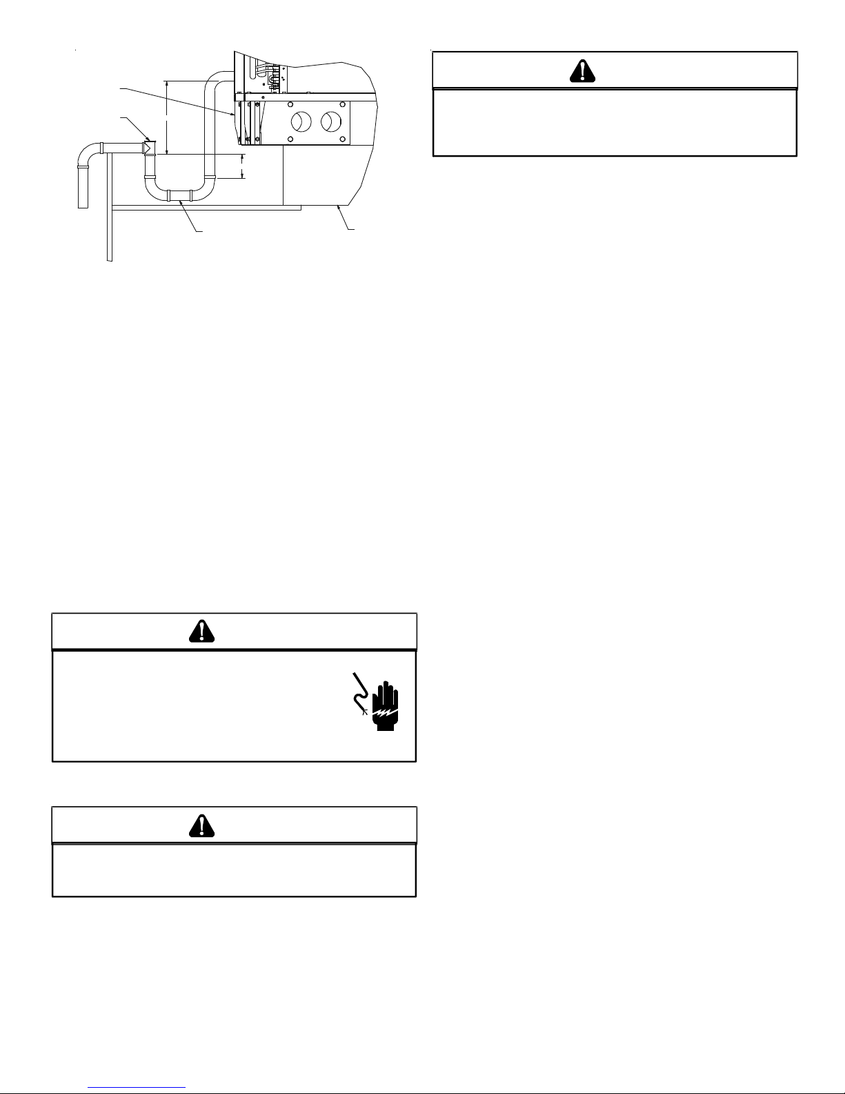
Base Rail
Open Vent
2” Min
See NOTE
Drain Plug
NOTE:
Trap should be deep enough to offset maximum
unit static difference. A minimum 4” trap is recommended.
DRAIN CONNECTION
Roof Curb
Install condensate drain trap as shown. Use 3/4” drain line and
fittings or larger. Do not operate without trap.
HORIZONTAL DRAIN
Drainage of condensate directly on to the r oof ma y be accept able;
refer to local code. It is recommended that a small drip pad of
either stone, mortar, wood or metal be provided to prevent any
possible damage to the roof.
CLEANING
Due to the fact that drain pans in any air conditioning unit
will have some moisture in them, algae and fungus will grow
due to airborne bacteria and spores. Periodic cleaning is
necessary to prevent this build-up from plugging the drain.
ST ARTUP, ADJUSTMENTS, AND CHECKS
WARN ING
WARN ING
MOVING MACHINERY HAZA RD!
O PREVENT POSSIBLE PERSONAL INJURY OR DEATH, DISCONNECT
T
POWER TO THE UNIT AND PADLOCK IN THE
SERVICNG FANS
.
“OFF”
POSITION BEFORE
HEATING STARTUP
On new installations, or if a major component has been replaced,
the operation of the unit must be checked.
Check unit operation as outlined in the following instructions. If
any sparking, odors, or unusual sounds are encountered, shut off
electrical power and recheck for wiring errors, or obstructions in
or near the blower motors. Duct cover s must be removed before
operating unit.
The Startup, Adjustments, and Checks procedure provides a s tepby-step sequence which, if follow ed, will assure the proper st artup
of the equipment in the minimum amount of time. Air balancing
of duct system is not considered part of this procedure. However,
it is an important phase of any air c onditioning syst em startup and
should be performed upon completion of the Startup, Adjustments ,
and Checks procedure. The St artup, Adjustment s, and Checks procedure at outside ambients below 55°F should be limit ed to a readiness check of the refrigera tion system with the requir ed final check
and calibration left to be completed when the outside ambient
rises above 55°F.
TEMPORARY HEATING OR COOLING
If the unit is to be used for tempor ary heating or cooling, a “Startup,
Adjustments, and Checks” must first be performed in accordance
with this manual. After the machine s are used f or temporary heat ing or cooling, inspect the coils, fans, and motors for unacceptable levels of construction dust and dirt and install new filters.
HIGH VOLTAGE!
T
O AVOID PERSONAL INJURY OR DEATH DUE TO
ELECTRICAL SHOCK, B
THE BUILDING ELECTRICAL GROUND BY USE OF THE
GROUNDING TERMINAL PROVIDED OR OTHER
ACCEPTABLE MEANS
SERVICING OR INSTALLING THIS UNIT
OND THE FRAME OF THIS UNIT TO
. D
ISCONNECT ALL POWER BEFORE
.
PRE-STARTUP INSTRUCTIONS
CAUTION
TO
PREVENT PROPERTY DAMAGE OR PERSONAL INJURY
START THE UNIT UNTIL ALL NECESSARY PRE-CHECKS AND TESTS
HAVE BEEN PERFORMED
.
, DO
NOT
Prior to the beginning of Startup, Adjustments, and Checks pr ocedures, the following steps should be completed in the building.
CONTRACTOR RESPONSIBILITY
The installing contractor must be certain that:
• All supply and return air ductwork is in place, properly
sealed and corresponds with installation instructions.
• All thermostats are mounted and wired in accordance
with installation instructions.
• All electric power, all gas, hot water or steam line
connections, and the condensate drain installation have
been made to each unit on the job. These main supply
lines must be functional and capable of operating all unit s
simultaneously.
• All filters are in place.
ROOF CURB INSTALLATION CHECK
Inspect the roof curb for correct installation. The unit and curb
assembly should be level. Inspect the flashing of the roof mounting curb to the roof, especially at the corners, for good workmanship. Also check for leaks around g a s kets. Note any deficiencies in
a separate report and forward to the contractor.
10

OBSTRUCTIONS, FAN CLEARANCE AND WIRING
Remove any extraneous construction and shipping materials that
may be found during this procedure. Rotate all fans manually to
check for proper clearances and that they rotate freely. Check for
bolts and screws that may have jarred loose during shipment to
the job site. Retighten if necessary. Re-tighten all electrical connections.
FIELD DUCT CONNECTIONS
Verify that all duct connections are tight and that there is no air
bypass between supply and return.
FILTER SECTION CHECK
Remove filter section access panels and check that filter s are properly installed. Note airflow arrows on filter frames.
PRE-STARTUP PRECAUTIONS
It is important to your safety that the unit has been properly
grounded during installation. Check gr ound lug connection in main
control box for tightness prior to closing circuit break er or disconnect switch. Verify that supply voltage on line side of disconnect
agrees with voltage on unit identification plate and is within the
utilization voltage rang e as indicate d in Appendix C Electrical Data.
System Voltage - That nominal voltage value assigned to a circuit
or system for the purpose of designating its voltage class.
Nameplate Voltage - That voltage assigned to a piece of equipment for the purpose of designating its voltage class and for the
purpose of defining the minimum and maximum voltage at which
the equipment will operate.
Utilization Voltage - The voltag e of the line terminals of the equipment at which the equipment must give fully satisfactory performance. Once it is established that supply voltage will be maintained within the utilization range under all system conditions,
check and calculate if an unbalanced condition exists between
phases. Calculate percent voltage unbalance as follows:
Three Phase Models Only
rating of the motor. The amperage must not exceed the service
factor stamped on the motor nameplate. The total airflow must
not be less than that required f or oper ation of the electric heat ers
or the furnace.
If an economizer is installe d, check the unit operating balance with
the economizer at full outside air and at minimum outside air. Upon
completion of the air flow balancing, we recommend replacing
the variable pitched motor sheave with a properly-sized fixed
sheave. A matching fix ed shea ve will provide longer belt and bear ing life and vibration free operation. Initially, it is best to have a
variable pitched motor sheave for the purpose of airflow balancing, but once the balance has been achieved, fixed sheaves maintain alignment and minimize vibration more effectively.
NOTE: Airflow setting below 300 CFM/ton is not recommended,
as evaporator freezing or poor unit performance is possible. For
2-speed models, airflow adjustments must be made with the
evaporator fan motor operating at high speed (in 2nd stage cooling or in heat mode). 2-Speed models have a “V” in 11th digit of
the model number (e.g. DCC300XXX3
V).
SET EVAPORATOR FAN RPM
Actual RPM’s mus t be set and verified with a tachomet er or strobe
light. Refer to Appendices A and B for basic unit fan RPM. Refer
also to “Airflow ” section of this manual. With disconnect switch
open, disconnect thermostat wires from terminals Y and W. This
will prevent heating and mechanical c ooling from coming on. Place
a jumper wire across terminals R and G at TB1 terminal block. Close
disconnect switch; evaporator fan motor will operate so RPM can
be checked.
EVAPORATOR FAN ROTATION CHECK (THREE PHASE MODELS ONLY)
Check that fan rotate s clockwise when viewe d fr om the driv e side
of unit and in accordance with rotation arrow shown on blower
housing. If it does not, reverse the two incoming power cables at
Single Point Power Block. In this case, repeat bearing check.
Do not attempt to change load side wiring. In ternal wiring assur e s
all motors and compressors will rotate in correct direction once
evaporator fan motor rotation check has been made.
2) MAXIMUM VOLTAGE DEVIATIONS
3) PERCENT VOLTAGE
UNBALANCE
HOW TO USE THE FORMULA:
EXAMPLE: With voltage of 220, 216, and 213
1) Average Voltage = 220+216+213=649 / 3 = 216
2) Maximum Voltage Deviation s fro m Average Voltage = 220 - 216 = 4
3) Percent Voltage Unbalance = 100 x = = 1.8%
Percent voltage unbalance MUST NOT exceed 2%
= 100 X
FROM AVERAGE VOLT AG E
1) AVERAGE VOLTAGE
4
216
AIRFLOW ADJUSTMENTS
The drive on the supply fan is typically set in the middle of the
RPM range. The drive motor she a v e pitch diameter is field adjustable for the required airflow. Refer to the following “Drive
Adjustments” section.
When the final adjustments are comple te, the curren t draw of the
motor should be checked and compared to the full load current
400
216
ELECTRICAL INPUT CHECK
Make preliminary check of evapor ator f an ampere dra w and verify
that motor nameplate amps are not exceeded. A final check of
amp draw should be made upon completion of air balancing of
the duct system (see Appendix C).
BELT DRIVE MODELS ONLY
BEARING CHECK
.
Prior to energizing any f ans, check and make sur e that all setscrew s
are tight so that bearings are properly secured to shafts.
TENSION AND ALIGNMENT ADJUSTMENT
Correct belt tension is very important to the life of your belt. Too
loose a belt will shorten its life; too tight, premature motor and
bearing failure will occur. Check you belt drive for adequate “runin” belt tension by measuring the force required to deflect the
11
 Loading...