

Daikin D-BACS Design Manual
ED 72 - 721
<Preliminary>
Daikin Buildings
Air-conditioning Control System
D-BACS
DESIGN GUIDE

i
Contents
1. Introduction ...................................................................viii
1-1 DAIKIN Building Air-conditioning Control System
(D-BACS) Overview ...... ................................................. . viii
1-2 Advantages of D-BACS over Automatic Control by
Central System................................................................viii
1-3 How to Use this Document.................................................x
1-4 Safety Precautions ........................ .....................................x
1-5 Open Network Glossary ....................................................xi
Part 1 Outline of D-BACS System .......................... 1
1. D-BACS (DAIKIN Building Air Conditioning Control
System) System Over View.............................................2
1-1 D-BACS System Integrated System Diagram................... 2
2. System Over View............................................................4
2-1 Targeted Project Scale and Map....................................... 4
2-2 Number of Group for Centralized-Control Devices
Connectable with Indoor-Units .......................................... 5
2-3 Control Function of the Devices ........................................ 5
3. List of D-BACS System Equipment................................6
3-1 List of Control System Equipment.....................................6
3-2 Main Specifications and Functions of the Equipment........8
4. List of Control System Equipment and Functions......14
5. Functions of Centralized Controllers...........................15
6. Central Control Equipment Combinations...................22
7. List of Applicable Models of DAIKIN............................23
Part 2 Fundamental of DIII-NET........................... 25
1. Design of DIII-NET..................................... .... ..... ..... .......26
1-1 Features of DIII-NET ....................................................... 26
2. DIII-NET Design Standard..............................................27
2-1 Terminal Number.............................................................27
2-2 Detail of Outdoor Unit Terminal No. ................................ 27
2-3 Connection Method......................................................... 28
3. Wiring Length.................................................................34
4. Unit and Group .......................................... .....................35
5. Number of Connectable Units.......................................36
5-1 Number of Connectable Units............... .......................... 36
5-2 Flow Chart to Determined the Number of Units to
Connected....................................................................... 37
5-3 Number of Units to be Connected [VRV]
(Supplementary Explanation)..........................................38
5-4 Connection of Devices other than VRV..................... ......39

ii
6. Group and Zone..............................................................40
6-1 Definition ......................................................................... 40
6-2 Patterns of Group and Zone............................................ 40
6-3 Group Address Number .................................................. 41
6-4 Setting Group No. for Centralized Control ....................... 4 2
6-5 Zone Address Number.................................................... 47
7. Wiring Specifications of DIII-NET .................................48
8. Combination of Multiple Central Remote Controllers
<DCS302CA61 • DCS301BA61 • DST301BA61>...........49
8-1 Check for Centralized Control Devices in
Simultaneous Use........... ................................................ 49
8-2 Combination of intelligent Touch Controller and
Central Remote Controller...............................................51
8-3 Combination of DCS302CA61·DCS301BA61·
DST301BA61 ..................................................................52
8-4 Sequential Start.................... ........................................... 54
8-5 Under Central Control ..................................................... 54
8-6 Error Code on Intial Setting and Wiring Troubles............ 54
Part 3 Remote Controllers ................................... 55
1. List of Indoor Units with Corresponding Individual
Operation Remote Controllers......................................56
2. Dimensions of Remote Controllers..............................58
2-1 Wired Remote Controller................................................. 58
2-2 Wireless Remote Controller / Receiver ........................... 59
2-3 Simplified Remote Controller........................................... 62
2-4 Remote Controller for Hotel Use ....... ..............................62
2-5 Wired Remote Controller with
Weekly Schedule Timer .................................................. 63
2-6 Wired Remote Controller for HRV................................... 63
3. Functions of Remote Controllers .................................64
3-1 Function List.................................................................... 64
3-2 Example of Control by Remote Controller.......................64
3-3 Remote Controller <BRC1C62>............ .......................... 65
3-4 Simplified Remote Controller
<BRC2C51 (BRC2A51)>................................................. 68
3-5 Remote Controller for Hotel Use <BRC3A61>................69
3-6 Wired Remote Controller with
Weekly Schedule Timer <BRC1D61>............................. 70
3-7 Wireless Remote Controller <BRC4C, 7C, 7E>..............72
3-8 Wired Remote Controller for HRV <BRC301B61>.......... 75
4. Various Control by Remote Controller Control...........76
4-1 Group Control.................................................................. 76
4-2 Forced OFF or ON/OFF Control...................................... 76
4-3 2 Remote Controllers ........... ........................................... 77
4-4 Remote Controller Thermostat........................................ 78
4-5 <KRCS01-1A> Remote Sensor..... ..................................80

iii
5. Field Setting by Remote Controller ..............................82
5-1 Wired Remote Controller <BRC1C62> ........................... 82
5-2 Wireless Remote Controller <BRC4C, 7C, 7E>..............85
5-3 Simplified Remote Controller
<BRC2C51 (BRC2A51)>................................................. 86
5-4 HRV <BRC301B61>........................................................ 88
Part 4 intelligent Touch Controller...................... 91
1. Part Names and Functions............................................92
1-1 Front and Side View.......... .............................................. 9 2
1-2 Part Names on the Monitoring Screen and
the Functions................................................................... 93
2. System Configuration....................................................99
2-1 System Outline................................................................ 99
2-2 Double intelligent Touch Controllers ............................... 99
3. Specification.................................................................100
3-1 Specification.................................................................. 100
3-2 Dimension .....................................................................100
4. Functions......................................................................101
4-1 Functions....................................................................... 101
5. Electric Wiring..............................................................104
5-1 Terminals on the Back of
intelligent Touch Controller... ......................................... 104
5-2 Points of Installation ...................................................... 105
5-3 Wiring for Force Stop Input and for
Electric Power Distribution ............................................ 106
5-4 Connection to Public Telephone Line............. ............... 107
5-5 Connection to LAN ........................................................ 107
5-6 DIII-NET Plus Adaptor Connection................................ 108
5-7 Connection for Unification Adaptor................................108
5-8 DII-NET Plus Adaptor.................... ................................109
5-9 Wiring Example for intelligent Touch Controller
(DCS601C51)................................................................ 111
6. Web function.................................................................117
Part 5 Control Devices ....................................... 123
1. <DCS302CA61> Central Remote Controller...............124
1-1 Function......................................................................... 124
1-2 System Configuration.................................................... 125
1-3 Specifications / Dimensions ....... ...................................128
1-4 Names and Functions of Operating Part.......................129
1-5 Description of Functions................................................131
1-6 Selection of Control Mode No. ................. ..................... 139
1-7 Initial Setting............................................. ..................... 142
1-8 Electric Wiring ...............................................................143
1-9 Special Function Settings.............................................. 144
1-10 Refreshed Operation..................................................... 145
1-11 Error Diagnosing Function............................................. 146
1-12 Installation ..................................................................... 149

iv
2. <DCS301BA61> Unified ON/OFF Controller ..............150
2-1 Function......................................................................... 150
2-2 System Configuration.................................................... 150
2-3 Specification and Dimension......................................... 151
2-4 Part names and Functions ............................................ 151
2-5 Initial Setting............................................. ..................... 153
2-6 Electric Wiring ...............................................................155
2-7 Confirming Operation ...... .............................................. 155
2-8 Installation ..................................................................... 156
3. <DST301BA61> Schedule Timer.................................157
3-1 Function......................................................................... 157
3-2 System Configuration.................................................... 157
3-3 Specification and Dimension......................................... 158
3-4 Part names and Functions (DST301BA61)................... 159
3-5 Initial Setting............................................. ..................... 161
3-6 Electric Wiring ...............................................................162
3-7 Installation ..................................................................... 163
3-8 Error Diagnosing Function............................................. 163
Part 6 intelligent Manager ................................. 165
1. intelligent Manager Overview......................................166
1-1 Features........................................................................ 166
1-2 Specification.................................................................. 176
1-3 Functions....................................................................... 177
2. System Design of intelligent Manager .......................178
2-1 System Configuration of intelligent Manager................. 178
2-2 List of Required Devices for
intelligent Manager System.. ......................................... 178
2-3 Creation of DIII-NET Wiring Diagram ............................ 179
2-4 Allocation of Centralized Address ......... ........................ 181
2-5 Points to Note for Design .............................................. 182
2-6 Use with Other Centralized Devices.............................. 183
3. Installation and Electric Wiring...................................184
3-1 Components..................................................................184
3-2 Part Name and Function ............... ................................184
3-3 Installation ..................................................................... 186
3-4 “DIII-NET master” setting ....... ....................................... 187
3-5 System Wiring ............................................................... 188
3-6 Electric Wiring Connection ............................................ 189
3-7 Setting group No. for centralized control.......................192
3-8 Wiring Example ............................................................. 193
Part 7 Interface for Use in BACnet®.................. 199
1. BACnet® Interface.............................................. ..... .....200
1-1 Outline and Features.....................................................200
1-2 System Outline.............................................................. 200
1-3 System Configuration.................................................... 201
1-4 Specifications ................................................................202

v
1-5 Components..................................................................202
1-6 Dimensions.................................................................... 202
1-7 BACnet Object List........................................................ 204
1-8 Names and Functions of each Part............................... 205
1-9 Electric Wiring ...............................................................207
1-10 Functions....................................................................... 212
1-11 Backup Systems for Troubles ....................................... 214
1-12 BMS (Building Management System) ........................... 216
1-13 Adopting “Super Wiring System”................................... 216
2. Daikin's Interface for
Use in BACnet® Agreement ........................................217
3. Wiring Example ............................................................219
3-1 Interface for Use in BACnet® (DMS502B51)................. 219
3-2 Interface for Use in BACnet
®
(DMS502B51)+
Optional Dlll Board (DAM411B51).................................220
3-3 Interface for Use in BACnet
®
(DMS502B51) with
P.P.D. Application Using Optional Di Board
(DAM412 B51)...............................................................221
Part 8 Interface for use in LONWORKS®........... 223
1. Introduction ..................................................................225
2. System Configuration..................................................226
3. Part Names and Functions..........................................227
4. Function........................................................................228
4-1 Overview of Functions................ ...................................228
4-2 Applicable Models ......................................................... 229
5. Specifications of Devices............................................230
6. Hardware.......................................................................231
6-1 Physical Appearance and Branch Connection..............231
6-2 Definition of LED and Switch......................................... 231
7. Object Details ...............................................................232
7-1 Node Objects...... ............................. .......................... ....232
7-2 DIII-NET Common Objects............................................ 232
7-3 Air Conditioner Objects .......... ....................................... 233
8. Precautions Regarding XIF Files................................234
8-1 File Name....... ............................................................... 234
8-2 Limitations with Version 3.............................................. 234
8-3 Unused Network Variables............................................ 234
9. Notes for when Commissioning .................................235
9-1 Suspension of Message Transmission when
Receiving Set Node Mode Online............ ..................... 235
10. Refere n ce Ma t eria l s
(Error Code Conversion Table)...................................236
11. Electric Wiring..............................................................237
11-1 Electric Wiring Connection ............................................ 237
11-2 Wiring Example .............................................................238

vi
12. Control-related Design Keypoints..............................239
12-1 Introduction.................................................................... 239
12-2 System Configuration....................................................239
12-3 Hardware....................................................................... 241
12-4 Outline of Functions ......................................................242
12-5 LON Communication Specifications.............................. 247
12-6 Monitoring and Control Restrictions..............................249
13. Workflow.......................................................................251
14. Check Sheet for Control and Monitoring Items.........252
Part 9 Power Proportional Distribution
(P.P.D.) ..................................................... 255
1. P.P.D. Design Guide.....................................................256
1-1 System Architecture ...................................................... 256
1-2 Design Preca u tions... .. .................................................. 25 7
1-3 Connection other than VRV........................................... 260
1-4 Conditions and Method to Exclude Calculation for
Specified Indoor Unit.....................................................261
1-5 Explanations of Power Proportional Distribution........... 262
1-6 Notes.............................................................................267
2. intelligent Touch Controller (DCS601C51) with
the Software for P.P.D. Application (DCS002C51)
Including PCMCIA........................................................269
3. intelligent Touch Controller (DCS601C51) with
the Software for P.P.D. Application (DCS002C51)
Including PCMCIA Card and with the Software for
WEB Usage (DCS004A51).................................. ..... .....270
4. intelligent Manager III (DAM602B51) with
P.P.D. Application ........................................................271
5. Interface for Use in BACnet® (DMS502B51) with
P.P.D. Application Using Optional Di Board
(DAM412 B51)...............................................................272
Part 10Adaptor .................................................... 273
1. Adaptor for System......................................................274
1-1 <DCS302A52> Unification Adaptor for
Computeriz ed C o n tr o l ...................................................274
1-2 <KRP2A61 / KRP2A62 / KRP2A53>
Wiring Adaptor for Electrical Appendices (1).................277
1-3 <DTA104A61 / DTA104A62 / DTA104A53>
External Control Adaptor for Outdoor Unit
(Must be Installed on Indoor Units) ...............................287
1-4 <DTA109A51> DIII-NET Expander Adaptor.................. 295
1-5 Dio Unit (DEC102A51)..................................................299
1-6 Di Unit (DEC101A51)...................................... ..............311
1-7 Ai Unit (DAM101A51).................................................... 320

vii
2. Adaptor for Indoor Unit and Other Equipment..........325
2-1 <KRP4A51 / KRP4A52 / KRP4A53 / KRP4A54>
Wiring Adaptor for Electrical Appendices (2)................. 325
2-2 <DTA102A52> Interface Adaptor for SkyAir Series.. ....334
2-3 <DTA112BA51> Interface Adaptor for
DIII-NET (SA) ................................................................ 337
2-4 <DTA107A55> Central Control Adaptor Kit........... ........338
2-5 <DTA103A51> Wiring Adaptor for
Other Air Conditioners................................................... 344
2-6 <KRP928B2S> Interface Adaptor for
DIII-NET (RA)................................................................ 348
2-7 <KRP1B61 / KRP1B56, 59 / KRP1C3>
Adaptor for Wiring ....... ................................................ .. 352
viii 1.1 DAIKIN Building Air-conditioning Control System (D-BACS) Overview
Introduction
1. Introduction
1.1 DAIKIN Building Air-conditioning Control System (D-BACS) Overview
D-BACS is a building air-conditioning control system built upon Daikin's unique high-speed multiplex ed-transmis sion
technology. D-BACS can integrate and centrally control various air-conditioners. With Daikin’s VR V system at the center
various Daikin air-conditioning units, such as total heat exchangers, SkyAir, room ai r-conditioners, package air-conditioners,
and screw chillers can be integrated into the system. D-BACS can be also combined with other third-party buildi ng facilities,
such as ventilation air blowers, pumps, and illuminations.
D-BACS can mainly control operations such as:
1. Starting/Stopping equipment operation
2. Setting temperatures
3. Setting air volume for indoor unit fans in VRV system and total heat exchanger
4. Switching of cooling and heating
5. Displaying abnormalities
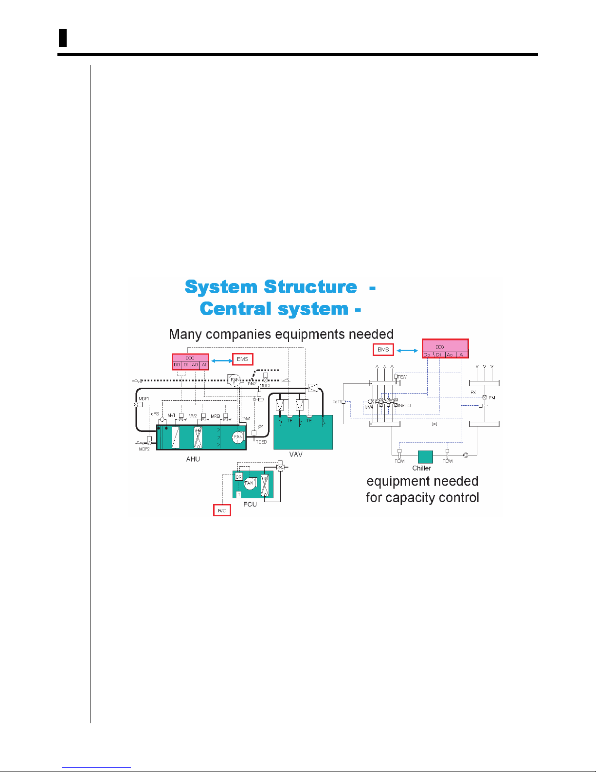
1.2 Advantages of D-BACS over Autom atic Control by Central System
To enable automatic control in a central system, a capacity control and remote control must be designed carefully for
each different third-party air-conditioner, thus requiring a special system engineer (SE).

1.2 Advantages of D-BACS over Automatic Control by Central System ix
Introduction
On the contrary, the D-BACS system built around VRV basically does not require such a design process for the capacity
control, because a detection unit (mainly sensors), an operation unit (mainly valves), and an adjustment unit etc. are
already incorporated in the product at the time of factory shipment.
Therefore, a general air-conditioner facility designer can design an air-conditioner facility around Daikin's VRV system
without special knowledge. In addition, D-BACS can fully satisfy control-related customer requirements.
Capacity Control Detection Units and Operating Units,
and Adjustment Units are incorporated into Indoor Units
and Outdoor Units.

x 1.3 How to Use this Document
Introduction
1.3 How to Use this Document
All the contents of this document are written for general air-conditioner facility designers. An air-conditioner facility
designer must provide the most economical and most efficient air-conditioner facility to end-users, comprehensively
taking all aspects of the air-conditioner into consideration, including air, water, refrigerant, environment, energy
consumption, and facility management. In particular, to allow efficient operation of the air-conditioner facility,
management or operation of the air-conditioning system must be examined thoroughly. All aspects of the management
and operation of the air-conditioning system must be designed based on user requirements.
Daikin's controlling equipment described in this document enables designers to fully satisfy user requirements.
Therefore, this document is an essential for source of information for air-conditioning system design.
This document covers almost all of the controlling equipment available from Daikin. This single document enables the
designers to explain the position or functions of equipment, required end-user operations, and prepare a proposal of the
air-conditioning system for a particular property. The designer of an air-conditioner facility can design a controlling
system for the property, and prepare the documents, such as below, for presentation to the end-user:
1. Equipment List: Types and quantities of equipment required
2. System Diagram: Diagram of connections between equipment items
3. Layout Plan for Controlling Equipment: Layout plan for each floor
4. Initial Settings: Minimum settings required for system operation, especially when there is a mixture of control
equipment types.
For the documentation required after satisfying the end user and obtaining the approval for the proposal, please refer to
installation guide an d operat ion guide f or the eq uipme nt for co nstructio n and te st -operati ons. Also, separa te En gineeri ng
Data are available for the following products. If more detailed information about anything from total planning to testoperation is required, or if you are an engineer specialized in control technology itself, our recommendation is to refer to
the Engineering Data:
1. intelligent Touch Controller ED72-423B
2. intelligent Manager ED72-746
3. BACnet
®
ED72-749
4. LONWORKS
®
ED72-333
1.4 Safety Precautions
Safety Precautions
For design, installation and maintenance, be sure to read the catalogue, this manual and the installation and operation
manual enclosed in the unit, and to follow their instructions.
Be sure to follow the “WARNING” (Failure to follow these instructions may cause a heavy injury or death.) and the
“CAUTIONS” (Failure to follow these instruction may cause the injury or damage on the property.) described in the
installation manual and etc.
<Cautions when designing the system>
1. Select the right products for your applications.
2. Be sure to consider the safety, electric shock and electric leakage when you design the system.
3. Be sure to follow the instructions in this manual for the operating range, characteristics of performance and limitation
for installation and etc.
<Cautions for the installation/operation>
1. Be sure to follow the safety pre-cautions described in the installation and operation manuals.
2. Be sure to install correctly according to the descriptions of the installation manual. Make sure to perform by the
authorized personnel the works such as a electrical work which requires the qualification.
3. Be sure to perform the commissioning of the system properly, and be sure that the power supply is correct and there
is no electric leakage and othe r abnorma lities , such as abnorma l sound , abnorm al smel l, smok e and etc. Also keep a
record of all the test operating data all the time.
4. Be sure to explain the contents of the ope ration m anual when you ha nd over th e job to the custo mer, and also as k the
customer to keep this manual wherever the operator can refer to all the time.
5. Hand over to the customer the warranty card duly filled.
1.5 Open Network Glossary xi
Introduction
<Cautions for maintenance>
1. Follow the instructions in the operation manual.
2. Be sure to perform the maintenance of the system properly, and be sure that the power supply is correct and there is
no electric leakage an d other a bnorma lities , suc h as abnorm al so und, ab normal smel l, sm oke an d etc. Al so rec ord all
the maintenance data and keep this record all the time.
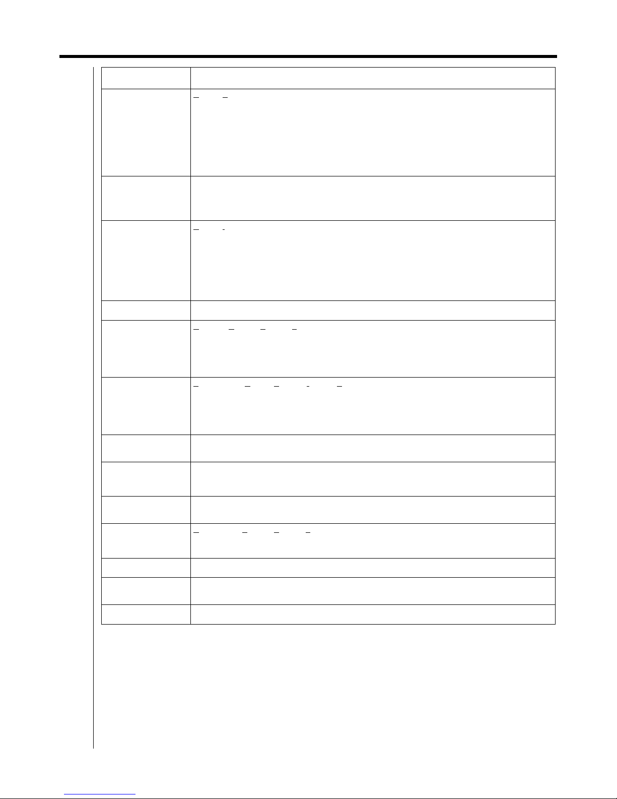
1.5 Open Network Glossary
Term Explanation
Ai Unit Connecting adapter that communicates information from environmental sensors (temperature, pressure,
humidity and voltage/electric current) to measurement unit.
ANSI A
merican National Standa r d s I nstitute
Architecture Refers to the overall design concept of the computer from hardware to software.
It is a systematic layout detailing the connection between the communications network and the devices in an
open network.
ASHRAE A
merican Society of Heating, Refrigeration and Air-conditioning Engineers, Inc.
BACnet B
uilding Automation Control Network
BAS B
uilding Automation System
Users: Building management engineers
Main functions: Facility device status monitoring
Alarm monitoring
Operation management (scheduling)
Automatic cont ro l o f fa c ilities
Bind Refers to one of the activities included in a test run. Specifically, the logical address is appropriated and
allocated.
Binding Refers to the logical connecting between the network variables that the user wishes to communicate.
It is a setting that enables communication of nvo from one device/machine and nvi from another. This is a job
usually handled by an NI.
BMS B
uilding Management System
Refers to a system for building management (management of electricity charges, equipment and the like).
BASs are configured within BMSs.
Users: Building management engineers
Main functions: Facility equipment ledger management
Repair history management
Maintenance schedule management
Billing data
Well known BMS manufacturers in Japan include NEC, YBS, YJ, Fujitsu, Panasonic and Oki.
Broadcast Refers to the simultaneous transmission of a message to all the devices connected in a system.
Messages involved in the communication between devices connected within a network are simultaneously
sent to all the devices within the network.
Centralized remote
controllers
Devices for collectively programming and managing operation of multiple air conditioners, installed in facility
from one or many locations.
Closed Network Refers to a system configured by only one manufacturer that does not allow access by other manufacturers.
DIII-NET is one such example.
Commission The work conducted when the central monitoring panel is connected to a gateway.
Specifically, the data within the gateway is sent to the central monitoring panel for data confirmation.
Refers to installation of settings in the node after the communication content is set via binding.
Communication Traffic
Volume
Refers to the traffic volume determined according to the number of nodes and network variables and the
frequency of communication between these two.
Configuration Property Refers to parameters related to the behavior of the LON nodes. Configuration properties are set for the
respective nodes by an NI when the network is being installed. They are assigned to the nodes' nonvolatile
memory. Unlike network variables, configuration properties represent semi-fixed variable values.
CRC C
entral Remote Controller
A device that allows remote controllers of up to 64 indoor units, groups or zones (total of 128 indoor units).
The single device provides centralized control to each connected indoor units for functions such as individual/
zone/simultaneous operation start/stop, room temperature control, etc. The device offers the same control
as individual remote controllers.

xii 1.5 Open Network Glossary
Introduction
Term Explanation
D-BACS It stands for D
aikin Building Air-conditioning Control System.
Means centralized air-conditioning management and control system based on highly expandable DAIKIN
original network communication
technology, DIII-NET. It is DAIKIN products that can be mainly controlled
through DIII-NET on D-BACS. And with various expander adapters connected , functions and usage of
control system can be expanded for following 3 sections of devices : 1) Equipment (electricity, plumbing,
elevator, ventilation, fire alarm, lighting, car park and crime/disaster prevention panel), 2) meters (electricity,
gas and water supply) and 3) environmental monitoring sensors (temperature, pressure, humidity and
voltage/current).
Di Unit Device by which DAIKIN centralized controllers are able to monitor operation and malfunction of up to 8
individual building facility equipment through DIII-NET, and pass them to centralized controllers. 'I' in Di
stands for INPUT from building facility equipment, and Di unit is only able to receive INPUT signal from
equipment, while Dio unit can receive operation signals from centralized controllers, and dictribute OUTOUT
signals to individual building equipment.
Dio Unit Device that is able to control operation, and monitor operation and malfunction for building equipment. 'I' in
Dio stands for INOUT from building facilities, while 'o' stands for OUTOUT to building facilities. This means
Dio unit can control building facility equipment for both ON and OFF operation. Di unit can only monitor ON
and OFF operation from building facility equipment.
DIII-NET Refers to Daikin Industries original communication network for A/C communications. (closed network)
Echelon The U.S. company that developed the LON.
Ethernet Refers to the name of and standard pertaining to a LAN product developed by Xerox.
Jointly developed by Xerox, DEC and Intel in 1980, Ethernet is the LAN used within BASs.
Free Topology Refers to a branched free-type connection arrangement within a network.
Daikin's Interface for LONWORKS
®
only supports free topology.
Gateway Refers to a device that translates the different communication codes sent between central monitoring panels
and A/C units to enable mutual communication.
It is used when more than one network is connected.
Interface for LONWORKS
®
and the Master Station are two such examples.
General Refers to the term 'general' used when conducting general or batch control. When controlling an entire
system, control is not conducted on each particular A/C unit, but on a generalized basis (all of the A/C units
together).
Group System of up to 16 indoor units controlled simultaneously from single or double remote controllers.
Heartbeat Refers to a function that cyclically communicates values of specific network variables.
Even if a main monitoring node does not request the data (does not confirm the status of the A/C unit), the
machine itself will automatically send the values. It allows the user to conclude that the node is operating
normally while this value is being sent.
HIM H
uman Interface Module
A device that incorporates the concept of the standard BAS protocol supported by the Institute of Electrical
Installation Engineers of Japan (IEIEJ). It enables the setting of parameters for status display, control and
monitoring of building equipment. It refers to a human interface device that performs On/Off operations and
the like.
Icont I
ntelligent Controller
A device that incorporates the concept of the standard BAS protocol supported by the IEIEJ. It is a control
device that is connected to either the building equipment or devices targeted for control via an interface. It
refers to a device that can support functions of independent monitoring, control and the like.
IEIEJ I
nstitute of Electrical Installation Engineers of Japan

1.5 Open Network Glossary xiii
Introduction
Term Explanation
IEIEJ Specifications Refers to the specifications established by the institute that determines them for the Japanese version of the
BACnet. (The international specifications must be certified, however, by ASRAE.)
The IEIEJ Specifications feature functions added onto the BACnet according to demand in the Japanese
market. Related discussions are currently being held with ASHRAE. The points of discussion are as follows:
1. Measurement: The data type used to calculate electric energy, heat and the like. This is absolutely
necessary in energy management.
2. Power demand: The method of determining the contract demand with electric power companies differs
with respect to the country. Accordingly, it is necessary in Japan to interpret the average electric power used
over 30 minutes as the maximum electricity demand.
3. Common data dissemination methods: Due to the common adoption of comprehensive monitoring
systems in Japan, it is necessary to have a system by which large volumes of disaster-related data can be
efficiently transmitted. This point has not been considered in the BACnet.
4. Collective objects: Devices that support several forms of data should be managed on a per device basis.
This will be proposed by the Japanese side (IEIEJ).
intelligent Manager III A centralized control system for VRV that can be connected to up to 1,024 indoor units. It features various
functions such as targeted power control function, fire alarm linkup, database maintenance and error
prediction (Air Conditioning Network Service System). These functions effect iv ely make it BMS speciali zed
for air conditioning. Synonyms: i-Touch Controller, Air Conditioning Network Service System. i-Manager is
served as the specialized air-conditioning control system.
intelligent
Touch Controller
Multi-function system management controller that allows you to operate and monitor up to 128 VRV indoor
units or 64 groups on colour LCD touch screen. It comes with functions that are combined with CRC, Unified
ON/OFF cobtroler and Schedule Timer. And it also includes applied functions such as electric power
distribution, Change Over Setting, Temperature Limit Setteing, Heating Optimization Settinfs. Furthermore,
this devise can be connected with LAN or public telephone line.
Interoperability Refers to the coordinated interlinking between related devices. An example of this is the control of lighting,
A/C, TV and the like with one R/C. If each of the respective companies involved uses a different protocol,
then they have to disclose their protocols and carry out discussions on several occasions to coordinate
efforts, which leads to an increase in costs. However, an open network essentially obviates such a situation
and allows machines manufactured by different companies to operate together without any problems. For
example, if A company's sensor breaks down, then it is possible to buy and install a product manufactured
by B company that will readily operate (interconnectivity). Different devices are, thus, able to communicate
and link up with each other.
iPU i
ntelligent Processing Unit
Units for use of Intelligent Manager III
I/O I
NPUT/OUTPUT
Examples: Di (Digital input), Do (Digital output), Ai (Analog input), Ao (Analog output)
LON L
ocal Operating Network
Refers to an intelligent distributed control network developed by the U.S. company, Echelon.
LONMARK The logo for products manufactured according to the guidelines established by the LONMARK Association.
LONMARK Refers to the LONMARK Interoperability Association.
The LONMARK Association is a nonprofit organization established to promote the use of LONWORKS. It
consists of some 350 companies from all over the world, including 19 from Japan.
The LONMARK Association was formed in order to create standard specifications for connection to LONs
between different vendors (companies).
LONMAKER Refers to the Echelon-developed tool (software) that allows installation commissioning (addressing), variable
binding, variable browsing (monitoring) and the like.
LONTALK Refers to the protocol used in LONs.
LONWORKS The generic term used to refer to the hardware, software, protocol and the like used to design, configure and
manage/service LONs.
Multi-vendor Refers to various machine/device manufacturers. The term 'multi-vendor envi ronm ent' is also often used.
Network Variable The unit in which data are sent/received in communication between nodes. There are two types: network
variable input (nvi) and network variable output (nvo).
Neuron Chip Refers to a LON chip. It is the interface used to access the LON.
xiv 1.5 Open Network Glossary
Introduction
Term Explanation
NI The acronym for N
etwork Integrator.
In the narrow sense, NI is the term used to refer to companies that have signed an NI contract with
ECHELON. In the broad sense, NI is the generic term used to refer to companies and engineers that
configure LONWORKS system networks proposed by ECHELON. The work of an NI is included in that of an
SI (system integrator) or SE (system engineer) in the case of computer systems. In LONWORKS systems,
the work of an NI involves network topology and network.
NI companies in Japan Obayashi Corporation
Takasago Thermal Engineering Co., Ltd.
DAI-DAN Co., Ltd.
NTT DATA Corporation
Hitachi Plant Engineering & Construction Co., Ltd.
Shimizu Corporation
Yukoukeisou Co., Ltd.
Chiyoda Keiso Co., Ltd.
System instrumentation Co., Ltd.
Hibiya Engineering, Ltd.
Shinryo Corporation
Mita Engineering Co., Ltd.
Taikisha Ltd.
Creight Co., Ltd.
Kyowa Exeo Corporation
As of August 2001
Node Refers to the devices connected by cable to the LON.
In other words, it refers to the devices to be controlled by the LON or BACnet.
VRV, valves and sensors are some examples.
nvi N
etwork Variable Input
nvo N
etwork Variable Output
Object Monitoring items and data.
Refers to something that regulates the operation of the object to be controlled.
The equivalent of a LON's SNVT or BACnet's object.
Open Network Refers to a network in which machines with different specifications are able to communicate with each other.
Profile In terms of a LON, the following are examples of items that are determined for each function of the respective
nodes in the LON:
- Network variable type
- Meaning of the network variable (function)
- Range and meaning of the network variable value (function).
Standardizing these ensures interconnectivity.
However, a LON is not configured for VRVs or PAs, so profiles for such A/C systems must be created by
each manufacturer in accordance with the respective network variable regulations. (Due to the fact that the
profiles differ with respect to the manufacturer, profiles such as those for VRVs and PAs are not certified by
LONMARK. However, because they conform with regulations, they can be treated as open networks by
disclosing the network variables.
Polling When the control station does not have the necessary data (the central monitoring panel does not have any
commands), it sends requests at regular intervals to each tributary station asking whether it has any data
transmission requests (data that the tributary station would like to communicate to the control station). The
control station sequentially gives each of the tributary stations request transmission rights, allowing them to
send the respective data.
Property Refers to each of the elements comprising an object.
Protocol The agreed rules and regulations used in communication between different computer programs.
When the protocol differs, two computer programs are unable to comprehend each other (communicate).
P.P.D It stands for P
ower Proportional Distribution
Proportional calculation of electric comsumption of VRV indoor unit
Router Refers to a device used for connections between different networks.
A router forwards data packets between networks. In an internal (in-company) LAN, it is used to connect the
LANs installed on a per floor basis. Meanwhile, a dial-up router is used to connect the Internet with a LAN.
Routers are also used for connections between an Ethernet and LON, for example, in the field of open
protocols used for building control.
R/C R
emote Controller
A Controller that let you individually control the operation of indoor unit for Air-conditioners
1.5 Open Network Glossary xv
Introduction
Term Explanation
SE S
ystem Engineer
System Engineer (SE) is a generic term used in the computer industry to refer to engineers who install
computers and communications devices for end-users. System engineers also generally conf i rm proper
operation of OS (operating software) and AS (application software) after set up. These capabilities are, of
course, necessary in the case of a BAS, but unlike the so-called computer systems, the SE must also
determine necessary specifications in order for vendors to manufacture systems that can effectively realize
functions and achieve desired performance levels detailed on the provided drawings. In addition, appropriate
instruction to and/or coordination between related parties, such as departments that design and create
hardware and software, according to the pertinent process as well as the promotion of smooth system
configurations are also responsibilities of the SE.
Selecting When a control station (central monitoring panel) sends data to a tributary station (DMS II or Interface for
LONWORKS
®
), a message is first sent to the latter to check if the data can be received. The data is then
sent upon receipt of an affirmative response from the tributary station (indicating that the data can be
received).
SI S
ystem Integrator
System Integrator (SI) is a generic term used in the computer industry to refer not only to the work of selecting
hardware and software suited to configured computer systems, setting up networks and altering software to
accompany the systems to be installed but also to the companies/engineers who perform the work. BASs,
including building management systems, represent a type of computer system, so the responsibilities of an
SI are the same. In addition, the responsibilities of the SI also include: a thorough understanding of functions
and features of the targeted electric equipment, A/C system and the like; coordination between hardware,
software and network designs provided by a multiple number of vendors; and smooth configuring of systems
to meet the objectives within a predetermined cost in cooperation with design supervisors and BA orderers.
Single Vendor Refers to a situation involving only one vendor or manufacturer.
SNVT S
tandard Network Variable Types
Refers to the variables used to control A/C units within LONs. These variables have been established by the
The Japan Refrigeration and Air Conditioning Industry Association (JRAIA) and are the standard variables in
Japan.
They are the equivalent of codes for control and monitoring items that enable interoperability in LONs.
(Predefined objects)
TCP-IP T
ransmission Control Protocol/Internet Protocol
TCP-IP is a standard protocol supported in all OS such as UNIX, an OS used in mid- to large-sized
computers, Windows and Mac.
TCP-IP was designed by an organization associated with the U.S. Department of Defense to allow for
communications between computers through another route even if a part or parts of a network were
destroyed.
Topology Refers to the connection arrangement within a network. Equivalent to the wiring method in DIII-NET. Star and
bus are some examples of topologies.
Unicast Refers to the sending of messages only to specified devices.
Specifically, it is the sending of messages between devices connected in a network on a one-to-one basis.
Unit Minimum unit of indoor unit or outdoor unit: One indoor unit shall be assumed to be one unit, and one outdoor
unit with refrigerating cycle shall be assumed to be one unit.
UNVT U
ser-defined Network Variable Types
Refer to the variables used to control A/C units within LONs. They are determined according to specific
projects (buildings, etc.) and, thus, are usually not used.
Vendor The seller or manufacturer
XIF File Refers to a file comprised of data containing network variables for LON nodes. The company manufacturing
the node (in this case, Daikin) creates the file and submits it to the NI upon receipt of an order for a system.
Zone A specified air-conditioning area that requires the same control in a building.

xvi 1.5 Open Network Glossary
Introduction

1
Part 1
Outline of D-BACS System
1. D-BACS (DAIKIN Building Air Conditioning
Control System) System Over View ....................2
1-1 D-BACS System Integrated System Diagram...................2
2. System Over View ................................................. 4
2-1 Targeted Project Scale and Map....................................... 4
2-2 Number of Group for Centralized-Control Devices
Connectable with Indoor-Units..........................................5
2-3 Control Function of the Devices........................................5
3. List of D-BACS System Equipment .....................6
3-1 List of Control System Equipment.....................................6
3-2 Main Specifications and Functions of the Equipment ....... 8
4. List of Control System Equipment and
Functions .............................................................14
5. Functions of Centralized Controllers................15
6. Central Control Equipment Combinations........22
7. List of Applicable Models of DAIKIN .................23
2 1.1 D-BACS System Integrated System Diagram
Outline of D-BACS System
1.
D-BACS (DAIKIN Building Air Conditioni ng Control System) System Over View
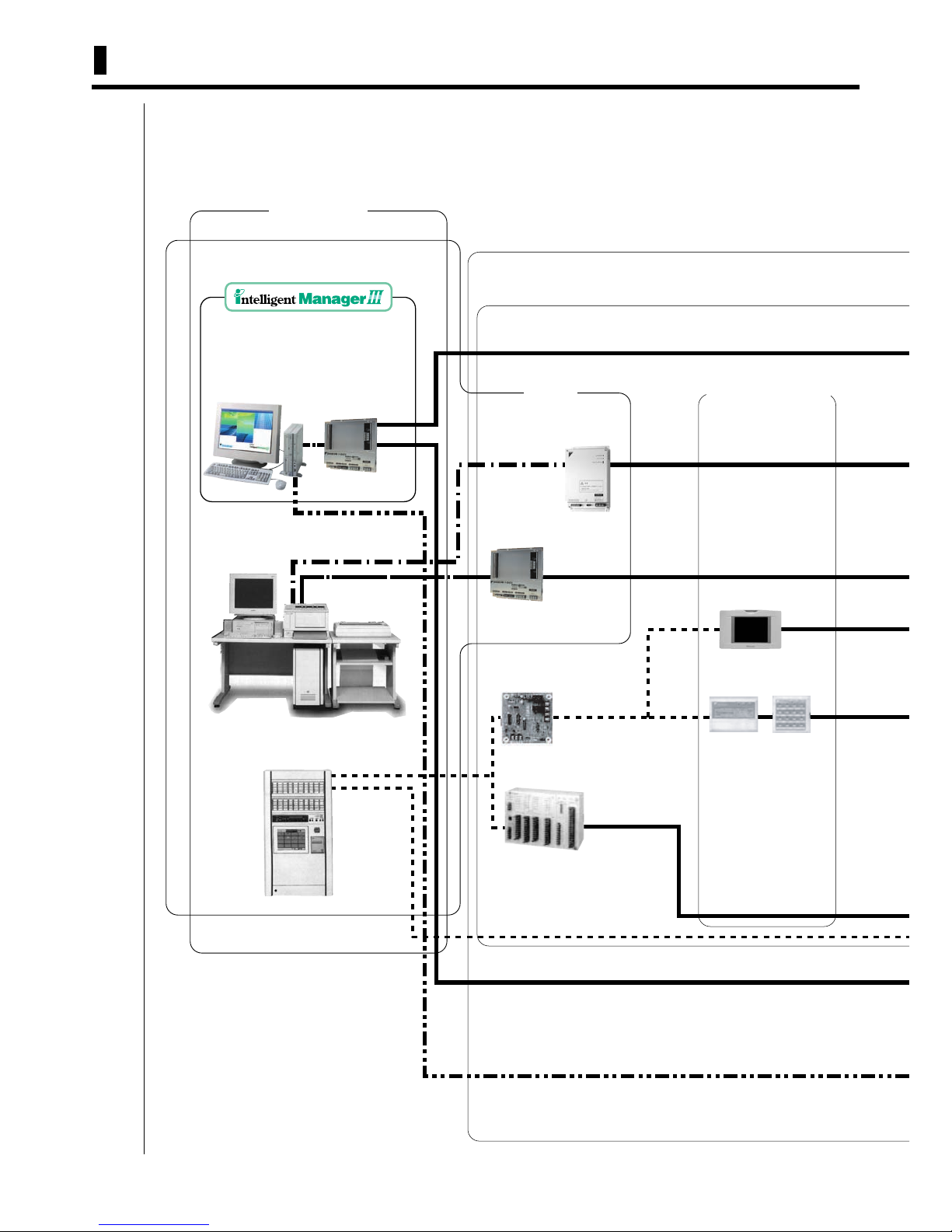
1.1 D-BACS System Integrated System Diagram
A variety of central control systems with high speed communication DIII-NET method are provided. By combining a
variety of controllers, the system implements not only advanced multiple operational controls for buildings but also
advanced building integrated monitoring systems that control a variety of building equipment.
D-BACS
System
Air Conditioning Control System
BMS / BAS
intelligent
Touch Controller
BAS
(field supplied)
BAS
(Field supplied)
Contact point
signal line
Interface for
Control /
connection
Central Remote
Control Equipment
for Air Conditioning
Unification
Adaptor for
computerized
control
Central
Remote
Controller
Unified ON/OFF
Controller
Parallel Interface
Upper
Upper middle/Middle
Interface for use
in BACnet
Interface for
use in
LONWORKS
Air-conditioner Data Management
System backed by the Building Multi
Communication Line DIII-NET. Airconditioner data can be directly
transferred without interface for
100% data management.
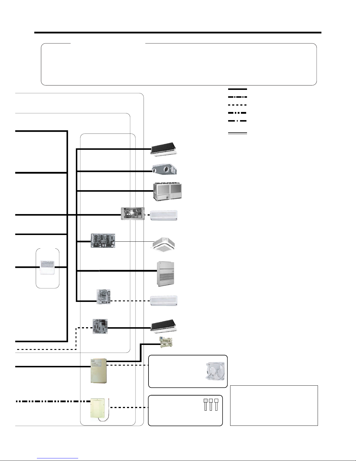
1.1 D-BACS System Integrated System Diagram 3
Outline of D-BACS System
TNP
Interfoce Adoptor for DIII -NET(RA)Interface Adaptor for DIII -NET(RA)
Extended Adaptor
VRV
Total Heat Exchanger
Unit HRV
Can be connected directly.
DAIKIN Air cooled
Water Chillers
SkyAir
(Round flow, wall mounted
type unnecessary)
Air Conditioner for Equipment
* Some models require adaptors
Room Air-conditioner
Room Air-conditioner
VRV
Interface Adaptor for
SkyAir series
Wiring Adaptor for
other air-conditioners
Wiring Adaptor for
Electrical Appendices
Dio Unit
Di Unit
Ai Unit
Building Equipment
CUWD Series DAIKIN
Water cooled (Chiller)
· Electric
equipment
· Elevator
· Plumbing
equipment
· Ventilating
equipment
· Automatic fire
alarm panel
· Illuminating lamps
· Parking facility
· Crime/disaster
prevention panel
Analog Input Equipment
Ai: · Temperature sensor
· Pressure sensor
· Humidity sensor
· Voltage/current monitoring
Note
Control function may vary according
to the model.
The expansion of the control system
requires discussions etc. beforehand.
Please enquire DAIKIN distributer
while you are studying.
DIII-NET line
RS232 communication line
Contact point signal line
Ai transmission line
LONWORKS
®
network
communication line
BACnet
®
/ Ethernet
Schedule
Timer
The features of DIII-NET
*
Integrates a variety of air-conditioning machines extending throughout a building while provides accurate control and monitoring.
* Reduces the wiring in a building by providing the nonpolar double wire system. The wiring work is easy to accomplish with
few faulty wiring.
* Later installation is also easy to accomplish. In total, up to two kilometers can be extended for wiring.
* A variety of controllers can be combined which also allows construction of a hierarchical risk diversification system.
* Our total heat exchangers and central air-conditioning machines can also be controlled totally.
Lower

4 2.1 Targeted Project Scale and Map
Outline of D-BACS System
2. System Over View
2.1 Targeted Project Scale and Map
1
560
R/C
Adaptors
Central remote
controller
intelligent Touch Controller
Unified ON/OFF
Controller
Schedule
Timer
Project scale (m2)
•A/C Management system
•Report,
•
Management of equipment
including other facilities
intelligent Manager
Ethernet
BMS
(Field Supply)
Functionality
• Report to BMS
•
A/C control from BMS
•
Management of equipment
including other facilities
LONWORKS
BACNET GATEWAY
•
Sophisticated A/C control
• Data collecting
1
5360
1152
0
7
6803840
2
880
192
0960960600
24
0

2.2 Number of Group for Centralized-Control Devices Connectable with Indoor-Units 5
Outline of D-BACS System
2.2 Number of Group for Centralized-Control Devices Connectable with Indoor-Units
2.3 Control Function of the Devices
Ex:On/Off, temperature, air flow and mode setting, operation and an malfunction display
DCS302CA61
[Central]
ModelName
[Dio]
[Schedule]
[ON/OFF]
[intelligent Touch Controller]
[intelligent Manager]
[Unification]
[BAC-net]
[Adaptor 2]
[Adaptor 1]
[KRP2A----]
[KRP4A----]
DCS302A52
DMS504B51
DAM502B51
(64Gp x
4 ports)
DAM602B51
+DCS601A52
DAM602B52
DCS601C51
DEC102A51
DST301BA61
DCS301BA61
Contact signal
Contact signal
Contact signal
DIII-NET
DIII-NET
DIII-NET
DIII-NET
DIII-NET
DIII-NET
DIII-NET
DIII-NET
DIII-NET
DIII-NET
DIII-NET
Communication
Lon Talk
BACnet
1
1
1
1
1
4
3
2
1
1
1
1
1
1
1
2
1
102476851225619212864401641
Qt
15 60 240 600
Gp.
m
2
1920 2880 3840 7680 11520 15360960
Batch operation
Possible PC Control
Individual operation
Reference floor space (m
2
)
based on the assumption as
1Gp. 1Hp equal to
15m
2
(+DCS302CA61, or DCS601C51)
[LONWORKS]
[Wired R/C]
[Adaptor 2]
[Adaptor 1]
[Unification]
[LONWORKS]
[BAC-net]
[intelligent Manager]
[intelligent Touch Controller]
[Dio]
[Schedule]
[ON/OFF]
[Central]
Name
For VRV I/UBRC1C62
[KRP2A----]
+DCS601A52
[KRP4A----]
DCS302A52
DMS504B51
DAM502B51
DAM602B51
(64Gp x
4 ports)
DAM602B52
DCS601C51
DEC102A51
DST301BA61
DCS301BA61
DCS302CA61
CommunicationModel
C/H Display
Error
For 1Gp. DisplayH/LFor 1Gp.
OperationModeFanTemperatureON/OFF
Signal for all
Code for Each Gp.
Code for Each Gp.
Signal for allSimultaneous control
Signal for 1Gp.For 1Gp.
Simultaneous
control
Code for Each Gp. For each Gp.
Code for Each Gp. For each Gp.
For each Gp.
For each Gp.
Code for Each Gp.For each Gp.
Code for Each Gp.For each Gp.
Code for Each Gp.For each Gp.
Code for Each Gp.For each Gp.
Code for Each Gp.For each Gp.
Signal for each Gp.For each Gp.
one lamp for all
Lamp for each Gp.For each Gp.
For each Gp.
Contact signal
Contact signal
Contact signal
Lon Talk
BACnet
DIII-NET
DIII-NET
DIII-NET
DIII-NET
DIII-NET
DIII-NET
DIII-NET
DIII-NET
DIII-NET
DIII-NET
DIII-NET
Simultaneous
control

6 3.1 List of Control System Equipment
Outline of D-BACS System
3. List of D-BACS System Equipment
3.1 List of Control System Equipment
Equipment using DIII-NET Unit Name Applied Model Page
Upper
intelligent Manager III DAM602B51/52
VRV series, SkyAir series,
Room Air-conditioner, HRV unit,
Other Air-conditioner
BACnet Interface DAM502B51
DMS-IF DMS504B51
Parallel Interface DPF201A51/52/53
Upper
middle
intelligent Touch Controller DCS601C51
Middle
Central remote Controller DCS302CA61
Unified ON/OFF controller DCS301BA61
Lower Schedule Timer DST301BA61
DIII-NET
expansion
adaptor
DIII-NET Plus Adaptor DCS601A52 intelligent Touch Controller
DIII-NET Expander Adaptor DTA109A51 VRV indoor units 295
Interface for
DIII-NET
Unification Adaptor for Computerized Control DCS302A52
intelligent Touch Controller &
Central remote Controller
274
Di/Dio Unit
DEC101A51/
DEC102A51
other facilities than air conditioners 299/ 311
Interface Adaptor for SkyAir Series DTA102A52 DAIKIN SkyAir series 334
Interface Adaptor for DIII-NET(SA) DTA112BA51 DAIKIN SkyAir series 337
Interface Adaptor for DIII-NET(RA) KRP928B2S DAIKIN Room Air-conditioner 348
Wiring Adaptor for Other Air-conditioners DTA103A51 DAIKIN Other Air-conditioner 344
Central control Adaptor Kit DTA107A55
DAIKIN FD series &
UAT(Y) series
338
External Control Adaptor for Outdoor Unit * DTA104A61/62/53 VRV outdoor units 287
Wiring Adaptor for Electrical Appendices (1) * KRP2A61/62/53 VRV indoor units 277

3.1 List of Control System Equipment 7
Outline of D-BACS System
*Note: Wiring Adaptor with "*" mark cannot be used with Upper, Upper middle, Middle, Lower grade equipment.
Equipment not using DIII-NET Unit Name Applied Model Page
Adaptor
Wiring Adaptor for Electrical Appendices (2) * KRP4A51/52/53/54 VRV indoor units 325
Adaptor for Wiring
KRP1B56/59/61,
KRP1C3
VRV indoor units 352
Equipment using DIII-NET Unit Name Applied Model Page
Ai Unit DAM101A51 intelligent Manager III 320
8 3.2 Main Specifications and Functions of the Equipment
Outline of D-BACS System
3.2 Main Specifications and Functions of the Equipment
For more effective localized envi ron me ntal control Daikin offers various cont rol sy stems such as single or double remo te
control or centralized control. This enables the construction of a variety of operational control systems which can be
adapted for various uses from remote control to building automation.
∗1 In case of group control, the remote controller used as master control must be selected with auto-swing function
(BRC1A61). When the group has cassette (FXC (Q)), FXF (Q)) or ceiling suspended (FXH (Q)) or cassette corner
(FXK (Q)) or wall mounted (FXA (Q)) models.
∗2 In case of using BRC2A51 (Simplified Remote Controller) to Heat Recovery Series, be sure not to use this
independently. Use with other remote controllers (BRC1A51 · 52, BRC1C62 or KRC19-26A or DCS302A51).
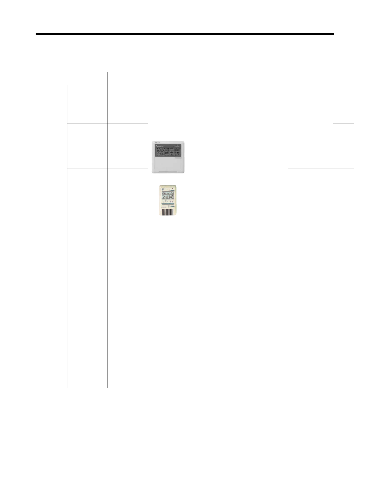
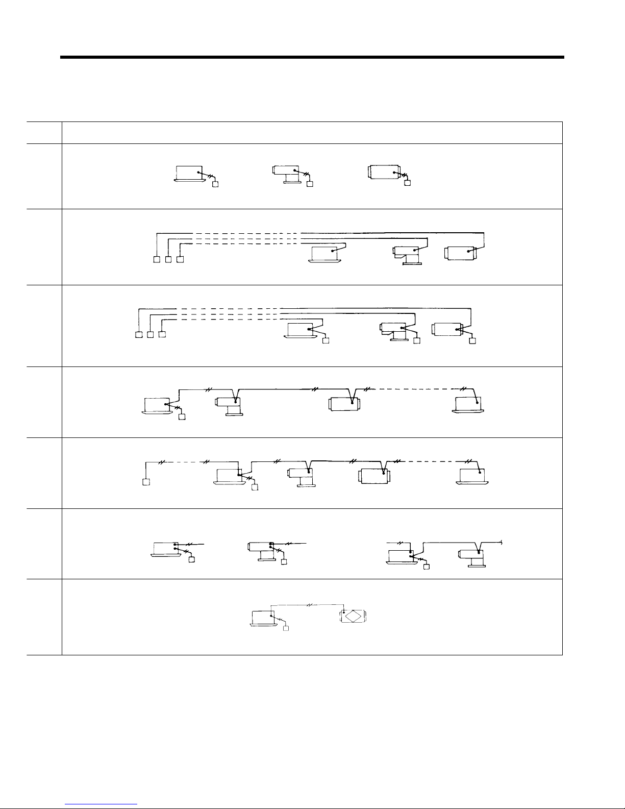
Control Method Objective / Use
Unit Name and
Model
Function
Standard Number of
Units
Control by Remote Controller
Local operation of
remote controller
Example of typical
use
BRC1C62
*2 BRC2C51
In the right
figure, a wired
remote
controller is
used for the
system
configuration.
However, the
same control is
available if the
controller is
replaced by a
wireless.
When using
two remote
controllers, it is
not possible to
set both of
them for
wireless
remote
controllers. Be
sure to set at
least one of
them for a
wired remote
controller.
Operational functions
Start/Stop (ON/OFF)
Operation Mode Selection
Temperature setting
Timer setting (Settings in units of 1 hour up to
a maximum of 72 hours)
Air flow settin g
Air flow direction adjustment (Swing flap)
Indication function
Operating display
Program dry function display
Defrost/Hot start display
Filter sign
Temperature setting display
Timer display
Air flow display
Abnormal operation display
∗
In case of group control all the indoor units in
the system are set to the same value and
each unit is controlled individually by its
internal thermostat. (Not by the thermostat
equipped in remote controller) In commond
case of double remote control the last
command priority. (Selection between main
and sub controller is essential)
Note)
Some functions cannot be set depending on the
shape of indoor unit.
1 remote controller
controls 1 indoor unit
Remote operation
of remote
controller
For control from
distant place
2 remote control
For control from 2
places (distant or
local)
2 remote controllers
control 1 indoor unit
Group control
∗
1
For the control of
plural indoor units
on a floor at the
same time
1 remote controller
controls up to 16
indoor units
simultaneously
∗
1
Group control by 2
remote controllers
For above control
from distant place.
2 remote controllers
control up to 16
indoor units from 2
different places
simultaneously
Forced OFF
command from
outside
Forced OFF for
forgetting to turn
equipment off, or
in times of an
emergency.
Forcibly stops indoor unit operation by
command from outside.
During remote controller group control, input a
command from outside to any one of the
indoor units.
Same as the number
of units controlled by
remote controller
Combining control
by remote
controller
Operation of other
equipment
combined with the
operation of
indoor unit
Operates HRV in accordance with indoor unit
operation.
Same as the number
of units controlled by
remote controller
3.2 Main Specifications and Functions of the Equipment 9
Outline of D-BACS System
Outline of System
For local operation of remote controller
For HRV
Remote controller Remote controller
Remote controller
Remote
controller
Remote
controller
Remote
controller
Available up to 500m respectively
Remote
controller
Remote
controller
Remote
controller
Remote
controller
Remote controller Remote controller
Available up to 500m respectively
Remote
controller
Communication wire is
available up to 500m
Remote controller
Remote controller
Communication wire is
available for 500m in total
Remote controller Remote controller
Remote
control
(V0097)
Forced /
OFF input
Forced /
OFF input
Forced
ON / OFF
input
zFor group control
Remote controller
HRV
10 3.2 Main Specifications and Functions of the Equipment
Outline of D-BACS System
Control Method Objective / Use
Unit Name and
Model
Function
Standard Number of
Units
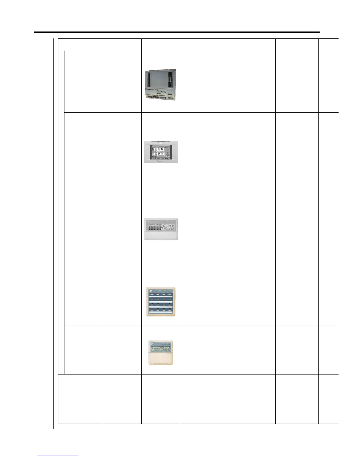
Central Control
intelligent
Manager III
For providing total
management of a
Daikin VRV
system as well as
equipment from
other
manufacturers,
such as air
conditioning,
lighting, and water
supply systems.
DAM602B51
Simple Operation and Management
Data Management
Total Building Management
Automated Operation Management
Web Access Function
Open Network Support
Air Conditioning Network Service System
Up to 1024 groups
(Max. 1024 indoor
units with P.P.D.)
intelligent Touch
Controller
For control all
indoor units just
like remote
controller
Provides three
remote control
fanctions, central
remote controller,
Unified ON/OFF
controller and
schedule timer.
DCS601C51
Adds various functions other than the
functions of existing central remote controller.
Scheduled operation and function to distribute
electricity proportionally.
Simple handling through a large sized liquid
crystal display.
Adopts a touch-panel
Twin centralized control function
Controls up to 64
groups (Max. 128
indoor units) with one
intelligent Touch
Controller.
Central remote
controller
For control all
indoor units just
like remote
controller
DCS302CA61
Double central control function
LCD remote control function is possible by
each indoor unit zone
Individual/unified operation
Up to 8 schedule patterns may be set with the
combined use of schedule timer.
Temperature setting by each zone
Individual room control operation at the time
of central control
Command to prohibit remote control
operation.
Sequential start function
Individual setting function of air blow direction
and volume
One central remote
controller may control
a maximum of 64
groups of indoor units
(However, up to 128
units)
Unified ON/OFF
controller
For ON/OFF
operate all indoor
units just like
remote controller
DCS301BA61
Double central control function
Indoor unit ON/OFF control
Individual/unified operation
Remote controller operation rejected
command (Central remote controller given
priority when used in combination with central
remote controller.)
Sequential start function
Controls up to 16
groups of indoor units
with one unified ON/
OFF controller.
Max. 128 units
Schedule timer
For carrying out
weekly schedule
operation by
1-minute units
DST301BA61
ON/OFF time can be set by units of day, hour
and minute; ON/OFF pattern can be set by
time zone of twice per day in accordance with
application.
Simultaneously
controls 64 groups
with one schedule
timer. Max. 128 units
Equipment control
system
Di/Dio Unit
Ai Unit
The use of this unit makes it possible to be
connected to facility equipment (for example,
pumps, illumination appliances, fans, etc.).

3.2 Main Specifications and Functions of the Equipment 11
Outline of D-BACS System
Outline of System
When using 1 unit of IPU
When using 1 unit of intelligent touch controller
When using one central remote controller
When using 1 unified ON/OFF controller
When using one unit of schedule timer
Note: For the schedule timer, take the electric power supply from the indoor unit.
intelligent
Manager III
Remote
controller
Remote
controller
Up to 1024 groups for group control
Up to 2048 units
for individual control
Power source
Single phase 100 - 240V
Maximum length of communication
wires for central control: 1 km
intelligent
touch controller
Remote
controller
Remote
controller
Up to 64 groups for group control
(however, up to 128 units can be controlled)
Up to 64 units
for individual control
Power source
Single phase 100 - 240V
Maximum length of communication
wires for central control: 1 km
Central
remote controller
Remote
controller
Remote
controller
Up to 64 groups for group control
(however, up to 128 units can be controlled)
Up to 64 units
for individual control
Power source
Single phase 100 - 240V
Maximum length of communication
wires for central control: 1 km
Unified
ON/OFF controller
Remote
controller
Remote
controller
Up to 16 groups for group control
(however, up to 128 units can be controlled)
Up to 16 units
for individual control
Power source
Single phase 100 - 240V
Maximum length of communication
wires for central control: 1 km
Schedule time
Electric power supply
for schedule timer
Maximum length of communication
wires for central control: 1 km
Up to 128 indoor units
can be controlled

12 3.2 Main Specifications and Functions of the Equipment
Outline of D-BACS System
Note) Central control units such as central remote controller cannot be used at the same time.
Control Method Objective / Use
Unit Name and
Model
Function
Standard Number of
Controllers
Building Control
System
Building control
computer,
air-conditioning
control computer
and control
system for
air-conditioning
are carried out by
communication
and contact
signal.
Interface for
use in BACnet®
DMS502B51
Optional DIII
board
DAM411A1
Optional Di
Board
DAM412A1
Parallel
interface
DPF201A51, 52, 53
Interface for
use in
LONWORKS
®
DMS504B51
Interface for use in BACnet
®
Interface unit to allow communications
between VRV and BMS.
Parallel interface
Carries out operation and monitoring function
of each indoor unit by contact and analog
signal.
Interface for use in LONWORKS
®
The LON Gateway functions as the interface for
a building monitoring system and cannot be winstalled on the DIII-NET along with following
equipment / devices that have similar functions.
Interface for use in
BACnet
®
:
Up to 256 indoor
units (256groups)
When the option DIII
board is used
Parallel Interface,
Interface for use in
LONWORKS
®
Up to 64 indoor units
(64 groups)
Power Proportional
Distribation (P.P.D)
Performs
monitoring of
accumulated
charges and
operation for each
indoor unit.
Intelligent Touch
Controller
i-Manager III
intelligent
Touch
Controller
(Proportional
division
software is
used)
Air conditioning charges are accumulated for
each indoor unit.
Registration can be made for each tenant.
Operation/stop/abnormality monitoring for an
indoor unit is available for each tenant.
A charge
management unit
can cover 64 indoor
units.
Adaptor
Wiring adaptor for
electrical
appendices (2)
For control by
operation
command from
BAS
With remote
temperature
setting
KRP4A51
KRP4A52
KRP4A53
KRP4A54
Built into indoor
unit
Normally open or momentary open type
contactor
12~24 VDC or no-voltage
Various control methods available by mode
select switch
Voltage, no-voltage selector switch
Alarm and operation display signal (novoltage)
Selector switch of zone/individual of alarm
display
Remote temperature setting (resistance input
of 0~135Ω)
Selector switch for remote controller
temperature setting enable/inhibit
∗
For group unified control, the setting becomes
the same for all connected indoor units, and
each indoor unit is controlled individually by
built-in thermostat.
∗
In case of using wiring adaptor for Electrical
Appendices (2), the control by 2 remote
controller is not available.
Function is the same as above.
Used only when 3 groups or more of HRV are
interlocked and operated.
∗
In case of integrated zone control, settings for
all indoor units connected to respective
groups become the same, and each indoor
unit is controlled by built-in thermostats.
1 PC board controls
1 indoor unit.
1 PC board
simultaneously
controls 1 group of
indoor units (max. 16
units).
Wiring adaptor for
electrical
appendices (1)
With remote
temperature
setting
KRP2A53
KRP2A61
KRP2A62
Built into indoor
unit
1 adaptor could
control a maximum
of 64 groups with 1
group consisting of a
maximum of 16 units
(up to 126 units in
total).
Adaptor for wiring
When controlling
operation with
optional
accessories added
inside indoor units,
the status is
displayed outside.
Built into indoor unit
KRP1B56, 57, 59, 61
KRP1C3
Necessary when electric heater and
humidifier are incorporated optionally
Operation indicating signal is made by taking
out compressor operation signal.
1 adaptor controls
electric heaters and
humidifiers.
Adaptor for
connection with
optional
controllers for
centralized control
For controlling all
indoor units from
one place
Unification
adaptor for
computerized
control
DCS302A52
Interface
adaptor for
SkyAir series
DTA102A52
Wiring adaptor
for other air
conditioners
DTA103A51
Unification adaptor for computerized control
allows you to simultaneously turn indoor units
connected to the central remote controller on
or off or display at the central monitor panel,
etc.
Interface adaptor for SkyAir series, wiring
adaptor for other air conditioners and wiring
adaptor for ‘H’ indoor unit are for connection of
optional controllers for centralized control.
Simultaneously controls
by one unification adaptor
for computerized control,
all indoor units connected
to a central remote
controller.
Controls one indoor unit by
one interface adaptor for
SkyAir series, wiring
adaptor for other air
conditioners, and wiring
adaptor for ‘G(J)’ indoor
unit.

3.2 Main Specifications and Functions of the Equipment 13
Outline of D-BACS System
Outline of System
Individual Control (Controls Indoor Units Individually.)
KRP1B56, 57, 59, 61, KRP1C3,
KRP2A61,62 and KRP4A51,52,53
can be built-in together into the
indoor units
Combined use of wiring adaptor for
Electrical Appendices (1) and (2) is not
available.
Group Unified Control (Controls group controlled indoor units all at once and simultaneously.)
Zone Unified Control (Unified, simultaneous control of up to 64 groups of group controlled indoor units
consisting of up to 16 units each.)
Intelligent touch controller
(Proportional division software is used)
Wh1
Power supply
Single phase 100-240V
Electric
meter
Electric
meter
Electric
meter
Outdoor unit
Outdoor unit Outdoor unit Outdoor unit
Outdoor unit
Power supply
Power supply
Power supply
Outdoor unit
Indoor unit Indoor unit Indoor unit
Wh2 Wh3
 Loading...