

Daikin BRC315D7 Operation manuals

BRC315D7
OPERATION MANUAL
Remote controller
1
13
3
12
4
11
NOT
AVAILABLE
12
9 1076 55 8
14
19
17
18
21
161520
1
BRC315D7 Remote controller Operation manual
THANK YOU FOR PURCHASING THIS
CONTROLLER. READ THE MANUAL
ATTENTIVELY BEFORE USING THE
INSTALLATION. AFTER READING THE
MANUAL, STORE IT IN A SAFE PLACE
FOR FUTURE USE.
Before initial operation, contact your dealer
to obtain all details concerning your air
conditioning installation.
The English text is the original instruction. Other
languages are translations of the original instructions.
This appliance is not intended for use by persons,
including children, with reduced physical, sensory or
mental capabilities, or lack of experience and
knowledge, unless they have been given supervision
or instruction concerning use of the appliance by a
person responsible for their safety.
Children should be supervised to ensure that they do
not play with the appliance.
Warning
- Never let the remote controller get wet, this may
cause an electric shock or fire.
- Never press the buttons of the remote controller
with a hard, pointed object. The remote controller
may be damaged.
- Never inspect or service the remote controller
yourself, ask a qualified service person to do this.
BRC315D7
Remote controller
4PW64949-1 – 10.2010
Contents page
1. Features and functions.........................................1
2. Name and function of switches and icons............2
3. Description of the operation modes......................3
4. Operation..............................................................3
5. Programming the ON/OFF timer ..........................5
6. Maintenance.........................................................6
7. Troubleshooting ....................................................6
1. Features and functions
The BRC315D7 is a remote controller that offers
control over your installation.
1 BASIC REMOTE CONTROLLER
The basic remote controller functions are:
• ON/OFF,
• operation mode change-over,
• temperature adjustment,
• air volume adjustment,
• air flow direction adjustment.
Operation manual
1
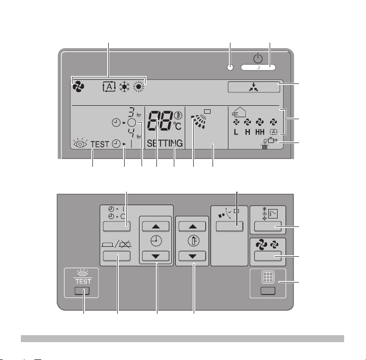
2. Name and function of switches and
(Refer to figure 1)
icons
1 ON/OFF BUTTON
Press the ON/OFF button to start or stop the system.
2 OPERATION LAMP
The operation lamp lights up during operation or
blinks if a malfunction occurs.
3 OPERATION MODE ICON
These icons indicate the current operation mode
(FAN, AUTOMATIC, COOLING, HEATING).
4 EXTERNAL CONTROL ICON
This icon indicates that another controller with higher
priority is controlling or disabling your installation.
5 ON/OFF TIMER ICON
This icon indicates that the ON/OFF timer is enabled.
6 INSPECTION REQUIRED
This icon indicates that inspection is required.
Consult your installer.
7 SET TEMPERATURE DISPLAY
This indicates the current set temperature of the
installation.
8 SETTING
Not used, for service purposes only.
9 AIR FLOW DIRECTION ICON
This icon indicates the air flow direction (only for
installations with motorised air flow flaps).
Operation manual
,
2
10 NOT AVAILABLE
is displayed whenever a non-installed option
is addressed or a function is not available.
When multiple indoor units are connected on the
same remote controller, " " will only be shown if
none of the connected units have this function.
11 FAN SPEED ICON
This icon indicates the set fan speed.
12 AIR FILTER CLEANING TIME ICON
This icon indicates the air filter must be cleaned.
Refer to the manual of the indoor unit.
13 INSPECTION/TEST OPERATION BUTTON
Not used, for service purposes only.
14 ON/OFF TIMER BUTTON
This button enables or disables the ON/OFF timer.
15 TIME ADJUST BUTTON
These buttons are used to adjust the timer, when in
programming mode, to adjust the programmed action
time. Both buttons have an auto-repeat function.
16 TEMPERATURE ADJUST BUTTONS
These buttons are used to adjust the current setpoint
(16~32°C) (step = 1°C).
17 OPERATION CHANGE BUTTON
This button can be used to select the operation mode
of the installation (FAN, AUTOMATIC, COOLING,
HEATING).
This function is default not available. This function is
activated when the jumper (J8) wire is cut off. See
installation manual on how to cut off the jumper (J8).
Remote controller
4PW64949-1 – 10.2010
BRC315D7
 Loading...