

Installer and user reference guide
+
-
Madoka wired remote controller
BRC1H82W
BRC1H82K
BRC1H82S

Table of contents
Table of contents
1 About the documentation 5
1.1 About this document ...................................................................................................................................................... 5
1.2 Meaning of warnings and symbols................................................................................................................................. 6
1.3 Installer and user reference guide at a glance............................................................................................................... 6
2 General safety precautions 8
2.1 For the installer............................................................................................................................................................... 8
2.2 For the user..................................................................................................................................................................... 9
3 Specific installer safety instructions 10
For the user 11
4 Remote controller: Overview 12
4.1 About the controller ....................................................................................................................................................... 12
4.2 Buttons............................................................................................................................................................................ 13
4.3 Status icons ..................................................................................................................................................................... 13
4.4 Status indicator ............................................................................................................................................................... 15
5 Operation 16
5.1 Basic usage...................................................................................................................................................................... 16
5.1.1 Home screen................................................................................................................................................... 16
5.1.2 Main menu...................................................................................................................................................... 17
5.2 Operation mode.............................................................................................................................................................. 18
5.2.1 About the operation modes ........................................................................................................................... 19
5.2.2 To set the operation mode ............................................................................................................................ 23
5.3 Setpoint........................................................................................................................................................................... 23
5.3.1 About the setpoint ......................................................................................................................................... 24
5.3.2 To set the setpoint ......................................................................................................................................... 26
5.4 Date and time.................................................................................................................................................................. 26
5.4.1 About date and time ...................................................................................................................................... 26
5.4.2 To set date and time....................................................................................................................................... 27
5.5 Airflow ............................................................................................................................................................................. 27
5.5.1 Airflow direction ............................................................................................................................................. 27
5.5.2 Fan speed........................................................................................................................................................ 28
5.6 Ventilation....................................................................................................................................................................... 30
5.6.1 Ventilation mode ............................................................................................................................................ 30
5.6.2 Ventilation rate............................................................................................................................................... 31
5.7 Advanced usage .............................................................................................................................................................. 31
Installer and user reference guide
2
6 Maintenance and service 32
6.1 Overview: Maintenance and service .............................................................................................................................. 32
7 Troubleshooting 33
7.1 Overview: Troubleshooting ............................................................................................................................................ 33
7.2 Refrigerant leak detection .............................................................................................................................................. 33
7.2.1 About refrigerant leak detection ................................................................................................................... 33
7.2.2 To stop the leak detection alarm ................................................................................................................... 34
For the installer 35
8 About the box 36
8.1 To unpack the controller ................................................................................................................................................ 36
9 Preparation 37
9.1 Wiring requirements....................................................................................................................................................... 37
9.1.1 To prepare the wiring for installation ............................................................................................................ 37
10 Installation 38
10.1 Overview: Installation ..................................................................................................................................................... 38
10.2 Mounting the controller ................................................................................................................................................. 38
10.2.1 About mounting the controller...................................................................................................................... 38
10.2.2 To mount the controller................................................................................................................................. 39
10.3 Connecting the electrical wiring ..................................................................................................................................... 40
10.3.1 Precautions when connecting the electrical wiring....................................................................................... 40
BRC1H82W+K+S
Madoka wired remote controller
4P596268-1 – 2020.12

Table of contents
10.3.2 To connect the electrical wiring..................................................................................................................... 40
10.4 Closing the controller...................................................................................................................................................... 41
10.4.1 Precautions when closing the controller ....................................................................................................... 41
10.4.2 To close the controller ................................................................................................................................... 41
10.5 Opening the controller ................................................................................................................................................... 42
10.5.1 Precautions when opening the controller..................................................................................................... 42
10.5.2 To open the controller ................................................................................................................................... 42
11 Starting up the system 43
11.1 Controller designation .................................................................................................................................................... 43
11.1.1 To designate a controller as slave.................................................................................................................. 44
12 Remote controller: Overview 45
12.1 About the controller ....................................................................................................................................................... 45
12.1.1 To configure the controller ............................................................................................................................ 46
12.2 Buttons ............................................................................................................................................................................ 46
12.3 Status icons ..................................................................................................................................................................... 47
12.4 Status indicator ............................................................................................................................................................... 48
12.4.1 Behaviour........................................................................................................................................................ 48
13 Operation 50
13.1 Basic usage ...................................................................................................................................................................... 50
13.1.1 Screen backlight ............................................................................................................................................. 50
13.1.2 Home screen................................................................................................................................................... 51
13.1.3 Information screen......................................................................................................................................... 52
13.1.4 Main menu...................................................................................................................................................... 53
13.2 Operation mode.............................................................................................................................................................. 54
13.2.1 About the operation modes........................................................................................................................... 54
13.2.2 To set the operation mode ............................................................................................................................ 58
13.3 Setpoint ........................................................................................................................................................................... 58
13.3.1 About the setpoint ......................................................................................................................................... 59
13.3.2 To set the setpoint ......................................................................................................................................... 61
13.4 Date and time.................................................................................................................................................................. 61
13.4.1 About date and time ...................................................................................................................................... 61
13.4.2 To set date and time....................................................................................................................................... 62
13.5 Airflow ............................................................................................................................................................................. 62
13.5.1 Airflow direction............................................................................................................................................. 62
13.5.2 Fan speed........................................................................................................................................................ 63
13.6 Ventilation ....................................................................................................................................................................... 65
13.6.1 Ventilation mode............................................................................................................................................ 65
13.6.2 Ventilation rate............................................................................................................................................... 66
13.7 Advanced usage .............................................................................................................................................................. 66
14 Configuration 67
14.1 Installer menu ................................................................................................................................................................. 67
14.1.1 About the installer menu ............................................................................................................................... 67
14.1.2 Screen settings ............................................................................................................................................... 68
14.1.3 Status indicator settings................................................................................................................................. 69
14.1.4 Field settings................................................................................................................................................... 69
14.1.5 Miscellaneous settings................................................................................................................................... 76
14.2 Software update ............................................................................................................................................................. 89
14.2.1 About software updates................................................................................................................................. 89
14.2.2 Software update with app.............................................................................................................................. 89
14.2.3 Software update with updating tool.............................................................................................................. 90
15 About the app 92
15.1 Operation and configuration overview .......................................................................................................................... 93
15.2 Pairing.............................................................................................................................................................................. 93
15.2.1 About pairing.................................................................................................................................................. 93
15.2.2 To pair the app with a controller ................................................................................................................... 93
15.2.3 To make a Bluetooth connection................................................................................................................... 94
15.2.4 To terminate the Bluetooth connection........................................................................................................ 96
15.2.5 To remove bonding information.................................................................................................................... 97
15.3 User access levels............................................................................................................................................................ 99
15.3.1 About user access levels................................................................................................................................. 99
15.3.2 Basic mode...................................................................................................................................................... 99
15.3.3 Advanced mode.............................................................................................................................................. 99
15.3.4 Installer mode................................................................................................................................................. 100
15.4 Demo mode .................................................................................................................................................................... 101
15.4.1 About demo mode ......................................................................................................................................... 101
15.4.2 To launch demo mode.................................................................................................................................... 101
BRC1H82W+K+S
Madoka wired remote controller
4P596268-1 – 2020.12
Installer and user reference guide
3

Table of contents
15.4.3 To exit demo mode ........................................................................................................................................ 101
15.5 Functions ......................................................................................................................................................................... 101
15.5.1 Overview: Functions....................................................................................................................................... 101
15.5.2 Remote controller firmware update.............................................................................................................. 104
15.5.3 Notifications ................................................................................................................................................... 104
15.5.4 Master/slave status........................................................................................................................................ 104
15.5.5 Screen............................................................................................................................................................. 104
15.5.6 Status indicator............................................................................................................................................... 105
15.5.7 Date and time................................................................................................................................................. 105
15.5.8 About .............................................................................................................................................................. 106
15.5.9 Remove bonding information........................................................................................................................ 106
15.5.10 Presence detection......................................................................................................................................... 106
15.5.11 OFF timer ........................................................................................................................................................ 107
15.5.12 Energy consumption....................................................................................................................................... 107
15.5.13 Power consumption limit ............................................................................................................................... 107
15.5.14 Setpoint auto reset ......................................................................................................................................... 107
15.5.15 Schedule ......................................................................................................................................................... 108
15.5.16 Holiday ............................................................................................................................................................ 108
15.5.17 Setpoint logic .................................................................................................................................................. 109
15.5.18 Setback............................................................................................................................................................ 110
15.5.19 Individual airflow direction............................................................................................................................. 111
15.5.20 Active airflow circulation ................................................................................................................................ 112
15.5.21 Setpoint range ................................................................................................................................................ 112
15.5.22 Cooling/Heating masterhood ......................................................................................................................... 112
15.5.23 Airflow direction range................................................................................................................................... 113
15.5.24 Draught prevention ........................................................................................................................................ 113
15.5.25 Quick start....................................................................................................................................................... 113
15.5.26 External input interlock .................................................................................................................................. 114
15.5.27 Defrost operation ........................................................................................................................................... 114
15.5.28 Function lock .................................................................................................................................................. 114
15.5.29 Quiet mode ..................................................................................................................................................... 116
15.5.30 Errors and warnings........................................................................................................................................ 116
15.5.31 Unit number ................................................................................................................................................... 116
15.5.32 Filter auto clean .............................................................................................................................................. 117
15.5.33 Filter notifications........................................................................................................................................... 117
15.5.34 AirNet address ................................................................................................................................................ 117
15.5.35 Group address ................................................................................................................................................ 117
15.5.36 Field settings ................................................................................................................................................... 118
15.5.37 Duty rotation .................................................................................................................................................. 119
15.5.38 Test operation ................................................................................................................................................ 120
15.5.39 Unit status....................................................................................................................................................... 122
15.5.40 Operating hours.............................................................................................................................................. 122
15.5.41 Contact information ....................................................................................................................................... 122
15.5.42 Active airflow circulation ................................................................................................................................ 122
15.5.43 Setting migration ............................................................................................................................................ 122
15.5.44 Supervised room address ............................................................................................................................... 123
15.5.45 Refrigerant leak alarm test ............................................................................................................................. 123
Installer and user reference guide
4
16 Maintenance 124
16.1 Maintenance safety precautions .................................................................................................................................... 124
16.2 About maintenance ........................................................................................................................................................ 124
16.3 To remove a warning screen .......................................................................................................................................... 126
16.4 To clean the controller.................................................................................................................................................... 126
16.5 Time to clean filter indication ......................................................................................................................................... 126
16.5.1 To remove the Time to clean filter indication ............................................................................................... 126
17 Troubleshooting 127
17.1 Error codes of the indoor unit ........................................................................................................................................ 127
17.2 Refrigerant leak detection .............................................................................................................................................. 129
17.2.1 About refrigerant leak detection ................................................................................................................... 129
17.2.2 To stop the leak detection alarm................................................................................................................... 129
18 Technical data 131
18.1 Connection diagram........................................................................................................................................................ 131
18.1.1 Typical layout.................................................................................................................................................. 131
18.1.2 Typical layout for group control..................................................................................................................... 131
18.1.3 Controller + DIII central control equipment .................................................................................................. 133
19 Glossary 134
BRC1H82W+K+S
Madoka wired remote controller
4P596268-1 – 2020.12
1 About the documentation
In this chapter
1.1 About this document.............................................................................................................................................................. 5
1.2 Meaning of warnings and symbols......................................................................................................................................... 6
1.3 Installer and user reference guide at a glance....................................................................................................................... 6
1.1 About this document
Target audience
Authorised installers + end users
Documentation set
This document is part of a documentation set. The complete set consists of:
▪ Installation and operation manual:
- Installation instructions
- Basic operation instructions
1 | About the documentation
▪ Installer and user reference guide:
- Extended installation and operation information
▪ Declaration of conformity:
INFORMATION: Declaration of conformity
Hereby, Daikin Europe N.V. declares that the radio equipment type BRC1H is in
compliance with the Directive 2014/53/EU. The original declaration of conformity is
available from the BRC1H product pages.
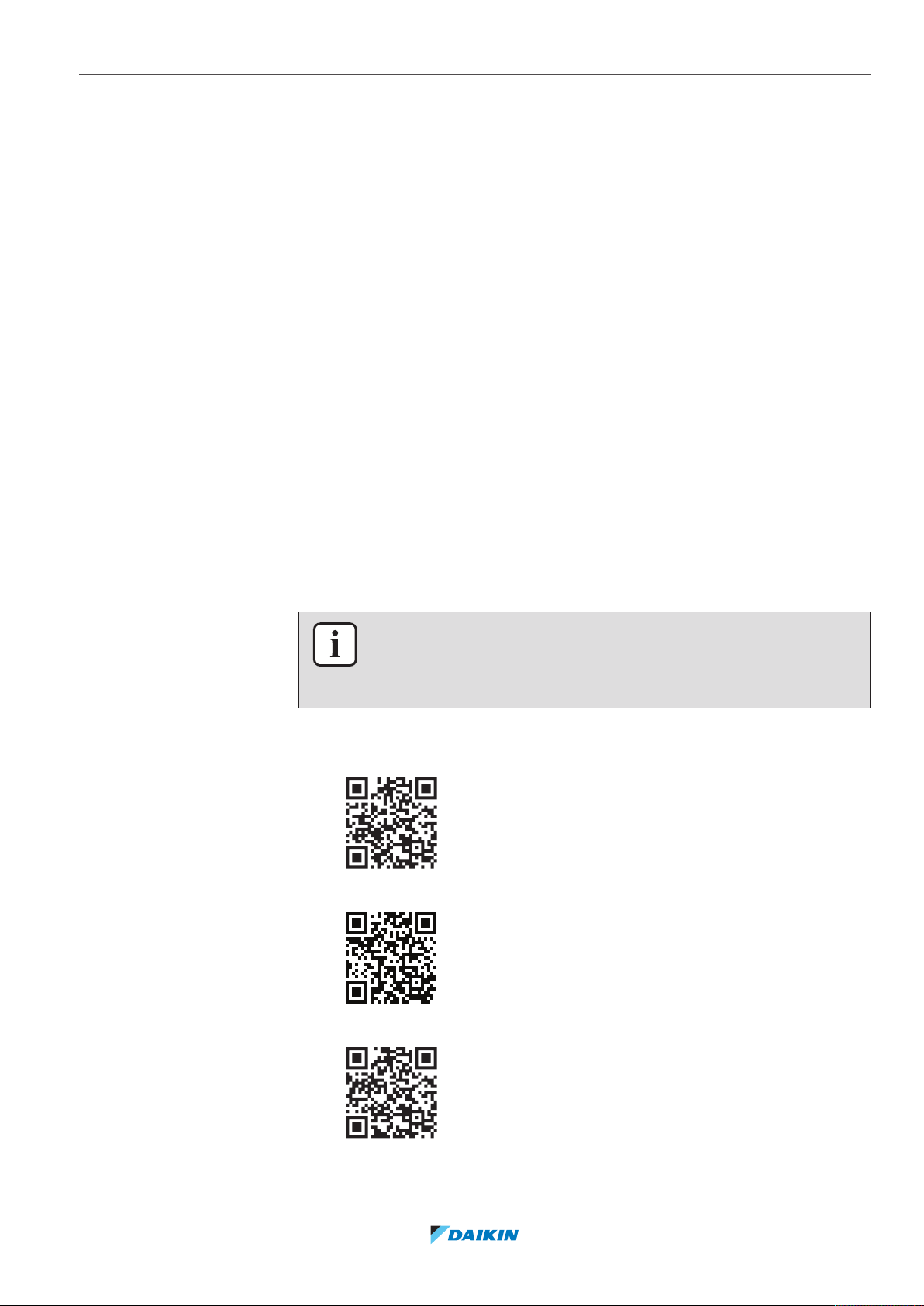
The documentation set is available from the BRC1H product pages:
▪ BRC1H82W: https://qr.daikin.eu/?N=BRC1H82W
▪ BRC1H82K: https://qr.daikin.eu/?N=BRC1H82K
BRC1H82W+K+S
Madoka wired remote controller
4P596268-1 – 2020.12
▪ BRC1H82S: https://qr.daikin.eu/?N=BRC1H82S
Installer and user reference guide
5
1 | About the documentation
Latest revisions of the supplied documentation may be available on the regional
Daikin website or via your dealer.
The original documentation is written in English. All other languages are
translations.
1.2 Meaning of warnings and symbols
INFORMATION: Madoka Assistant in-app documentation
The controller only allows for basic settings and operation. Advanced settings and
operation are performed via the Madoka Assistant app. For more information, see
the app and its in-app documentation. The Madoka Assistant app is available from
Google Play and the Apple Store.
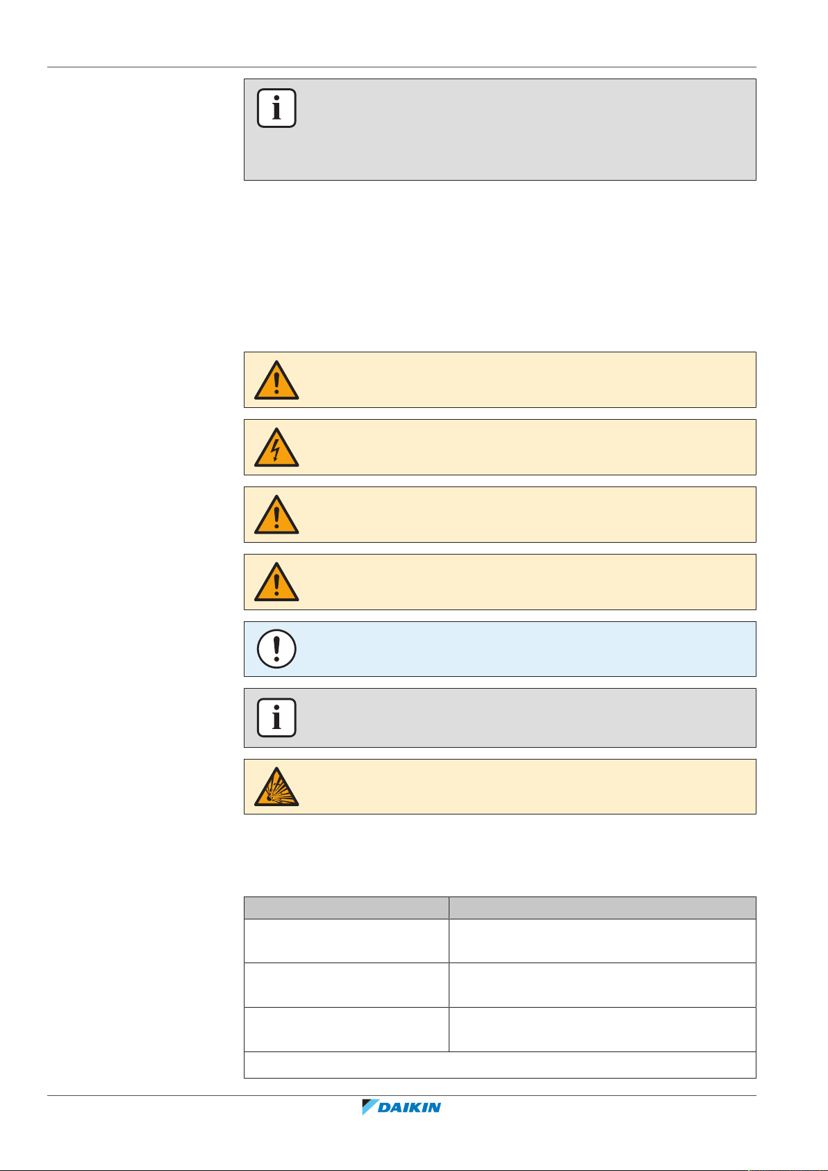
DANGER
Indicates a situation that results in death or serious injury.
DANGER: RISK OF ELECTROCUTION
Indicates a situation that could result in electrocution.
WARNING
Indicates a situation that could result in death or serious injury.
CAUTION
Indicates a situation that could result in minor or moderate injury.
NOTICE
Indicates a situation that could result in equipment or property damage.
INFORMATION
Indicates useful tips or additional information.
DANGER: RISK OF EXPLOSION
Indicates a situation that could result in explosion.
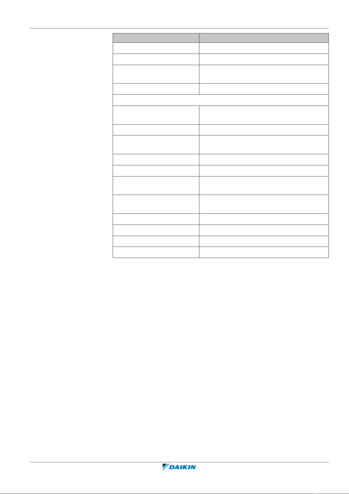
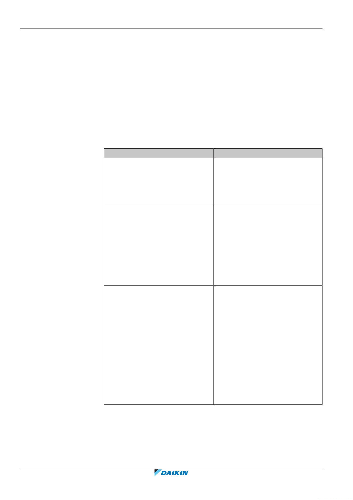
1.3 Installer and user reference guide at a glance
Installer and user reference guide
6
Chapter Description
About the documentation What documentation exists for the installer and
the user
General safety precautions Safety instructions that you must read before
installing
Specific installer safety
instructions
Safety instructions that the installer must read
before installing
For the user
Madoka wired remote controller
BRC1H82W+K+S
4P596268-1 – 2020.12
1 | About the documentation
Chapter Description
Remote controller: Overview Overview of the remote controller
Operation How to operate the remote controller
Maintenance and service How to maintain and service the remote
controller
Troubleshooting What to do in case of problems
For the installer
About the box How to unpack the remote controller and
remove the accessories
Preparation What to do and know before going on‑site
Installation What to do and know to install the remote
controller
Starting up the system How to start up the remote controller
Remote controller: Overview Overview of the remote controller
Configuration What to do and know to configure the system
after it is installed
About the app What to do and know to commission the remote
controller after it is configured
Maintenance How to maintain the remote controller
Troubleshooting What to do in case of problems
Technical data Specifications of the system
Glossary Definition of terms
BRC1H82W+K+S
Madoka wired remote controller
4P596268-1 – 2020.12
Installer and user reference guide
7
2 | General safety precautions
2 General safety precautions
In this chapter
2.1 For the installer....................................................................................................................................................................... 8
2.2 For the user............................................................................................................................................................................. 9
2.1 For the installer
The precautions described in this document cover very important topics, follow
them carefully.
INFORMATION
This controller is an option and cannot be used standalone. Also see the installation
and operation manual of the indoor and outdoor units.
WARNING
Improper installation or attachment of equipment or accessories could result in
electrical shock, short-circuit, leaks, fire or other damage to the equipment. Only use
accessories, optional equipment and spare parts made or approved by Daikin.
WARNING
All field wiring and components MUST be installed by a licensed electrician and
MUST comply with the applicable legislation.
NOTICE
The remote controller MUST be mounted indoors.
NOTICE
When the controller is used as room thermostat, select an installation location where
the average temperature in the room can be detected.
Do NOT install the controller in the following places:
▪ In places where it is exposed to direct sunlight.
▪ In places where it is near a heat source.
▪ In places that are affected by outside air or air draught due to e.g. door opening/
closing.
▪ In places where the display can easily get dirty.
▪ In places where there is NO easy access to the controls.
▪ In places with temperatures <–10°C and >50°C.
Installer and user reference guide
8
▪ In places where the relative humidity is >95%.
▪ In places where there is machinery that emits electromagnetic waves.
Electromagnetic waves may disturb the control system, and cause malfunction of
the equipment.
▪ In places where it may be exposed to water, or in generally moist areas.
If you are NOT sure how to install or operate the unit, contact your dealer.
After finishing installation:
BRC1H82W+K+S
Madoka wired remote controller
4P596268-1 – 2020.12
2.2 For the user
2 | General safety precautions
▪ Conduct a trial operation to check for faults.
▪ Explain the user how to operate the controller.
▪ Ask the user to store the manual for future reference.
INFORMATION
Consult your dealer regarding the relocation and reinstallation of the controller.
WARNING
To clean the controller, do NOT use organic solvents, such
as paint thinner.
WARNING
Do NOT use flammable materials (e.g. hairspray or
insecticide) near the controller.
WARNING
To prevent electric shocks or fire:
▪ Do NOT operate the controller with wet hands.
▪ Do NOT disassemble the controller and touch interior
parts. Contact your dealer.
▪ Do NOT modify or repair the controller. Contact your
dealer.
▪ Do NOT relocate or reinstall the controller by yourself.
Contact your dealer.
WARNING
Do NOT play with the unit or its remote controller.
Accidental operation by a child may result in impairment
of bodily functions and harm health.
BRC1H82W+K+S
Madoka wired remote controller
4P596268-1 – 2020.12
Installer and user reference guide
9
3 | Specific installer safety instructions
3 Specific installer safety instructions
Always observe the following safety instructions and regulations.
CAUTION
Never touch the internal parts of the controller.
CAUTION
When closing the controller, be careful not to pinch the wiring.
CAUTION
Before starting up the system, make sure:
▪ The indoor and outdoor unit wiring is completed.
▪ The switch box covers of the indoor and outdoor units are closed.
CAUTION
When connecting the controller to the indoor unit, make sure the indoor unit
switchbox and transmission wiring are not connected.
WARNING
All field wiring and components MUST be installed by a licensed electrician and
MUST comply with the applicable legislation.
WARNING
Before carrying out any maintenance or repair activities, stop system operation with
the controller, and turn off the power supply circuit breaker. Possible consequence:
electric shock or injury.
WARNING
Do not wash the remote controller. Possible consequence: electric leakage, electric
shock, or fire.
Installer and user reference guide
10
Madoka wired remote controller
BRC1H82W+K+S
4P596268-1 – 2020.12

For the user
For the user
BRC1H82W+K+S
Madoka wired remote controller
4P596268-1 – 2020.12
Installer and user reference guide
11
4 | Remote controller: Overview
4 Remote controller: Overview
In this chapter
4.1 About the controller ............................................................................................................................................................... 12
4.2 Buttons.................................................................................................................................................................................... 13
4.3 Status icons............................................................................................................................................................................. 13
4.4 Status indicator....................................................................................................................................................................... 15
4.1 About the controller
Depending on configuration, the controller is operable in either one of three
modes. Each mode offers different controller functionality.
Mode Functionality
Normal The controller is fully functional.
All functionality described under
"5Operation"[416] is available.
The controller can be a master or a
slave controller.
Alarm only The controller only acts as leak
detection alarm for a single indoor unit.
No functionality described under
"5Operation"[416] is available.
For information on the leak detection
alarm, see "7.2Refrigerant leak
detection"[433].
The controller can be a master or a
slave controller.
Supervisor The controller only acts as leak
detection alarm for the whole system,
i.e. multiple indoor units and their
respective controllers. This mode is
intended for a controller that is to be
used in a supervision location, e.g. the
reception desk of a hotel.
No functionality described under
"5Operation"[416] is available.
For information on the leak detection
alarm, see "7.2Refrigerant leak
detection"[433].
Installer and user reference guide
12
The controller can only be a slave
controller.
For more information on how to set the controller to be operable in a specific
mode, see "To configure the controller"[446]. When using “Supervisor” mode, it
is important to set the supervised room address in order to know for which indoor
unit the refrigerant leak alarm occurs. See "Supervised room address"[4123] for
more inormation.
BRC1H82W+K+S
Madoka wired remote controller
4P596268-1 – 2020.12
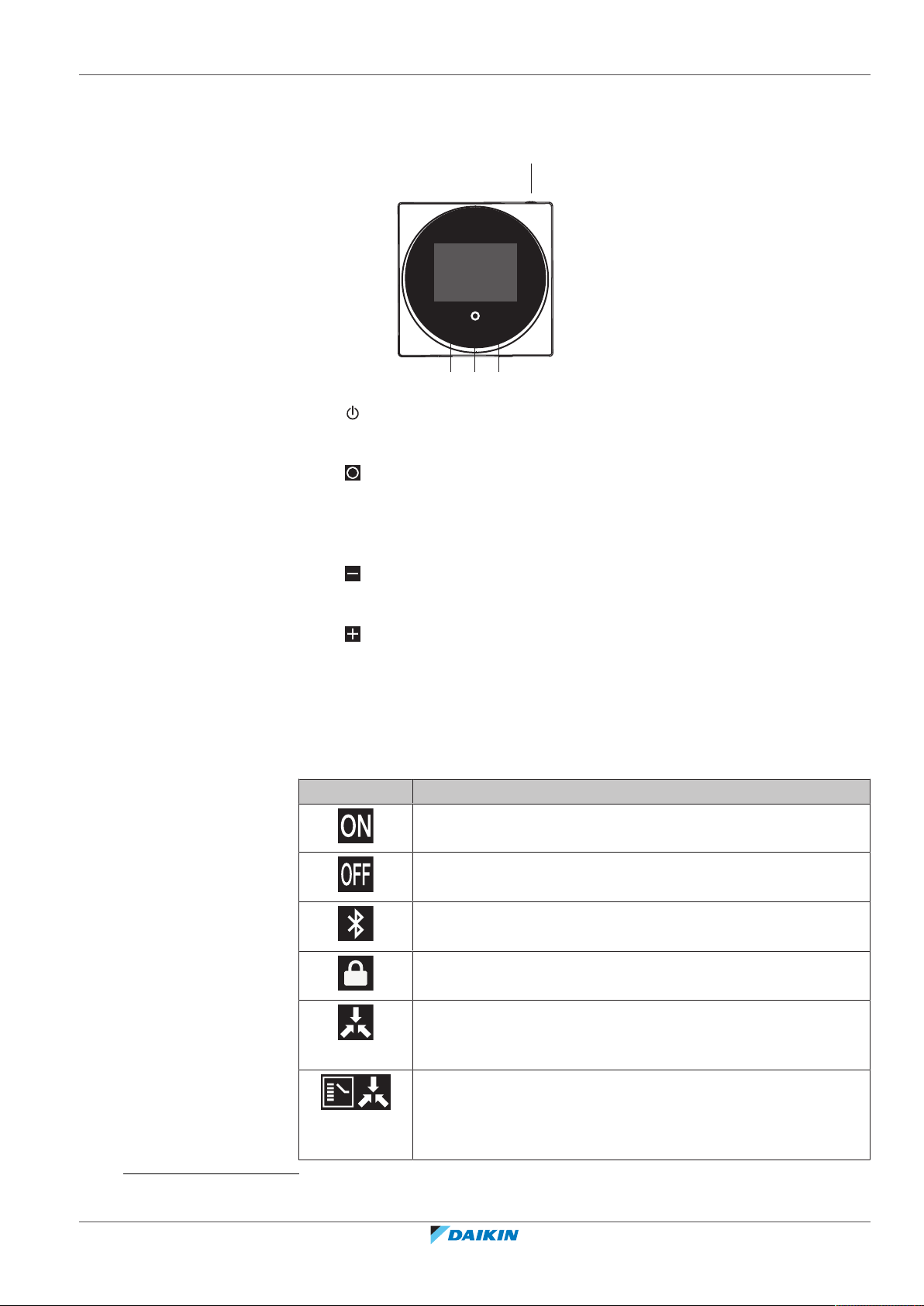
4.2 Buttons
+
-
c b d
a
4 | Remote controller: Overview
a
ON/OFF
▪ When OFF, press to turn ON the system.
▪ When ON, press to turn OFF the system.
b
ENTER/ACTIVATE /SET
▪ From the home screen, enter the main menu.
▪ From the main menu, enter one of the submenus.
▪ From their respective submenu, activate an operation/ventilation mode.
▪ In one of the submenus, confirm a setting.
c
CYCLE/ADJUST
▪ Cycle left.
▪ Adjust a setting (default: decrease).
d
CYCLE/ADJUST
▪ Cycle right.
▪ Adjust a setting (default: increase).
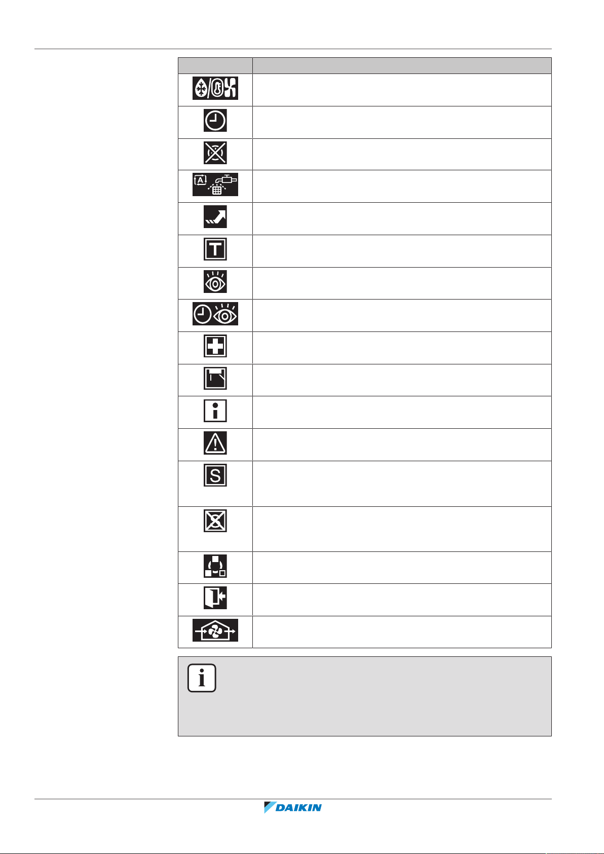
4.3 Status icons
(1)
The Bluetooth® word mark and logos are registered trademarks owned by the Bluetooth SIG, Inc. and use of such marks
by Daikin Europe N.V. is under license. Other trademarks and trade names are those of their respective owners.
BRC1H82W+K+S
Madoka wired remote controller
4P596268-1 – 2020.12
Icon Description
System operation ON. Indicates that the system is in operation.
System operation OFF. Indicates that the system is NOT in
operation.
Bluetooth.
(1)
Indicates that the controller is communicating with
a mobile device, for use with the Madoka Assistant app.
Lock. Indicates that a function or operation mode is locked and
therefore cannot be used or selected.
Centralised control. Indicates that the system is controlled by
central control equipment (optional accessory) and that control
of the system by the controller is limited.
Changeover under centralised control. Indicates that the
cooling/heating changeover is under centralised control by
another indoor unit, or by an optional cool/ heat selector that is
connected to the outdoor unit.
Installer and user reference guide
13
4 | Remote controller: Overview
Icon Description
Defrost/Hot start. Indicates that the defrost/hot start mode is
active.
Schedule/Timer. Indicates that the system operates according to
a schedule, or that the OFF timer is enabled.
Time not set. Indicates that controller's time is not set.
Self-cleaning filter operation. Indicates that self-cleaning filter
operation is active.
Quick Start. Indicates that Quick Start mode is active (Sky Air
only).
Test operation. Indicates that Test Operation mode is active (Sky
Air only).
Inspection. Indicates that the indoor or outdoor unit is being
inspected.
Periodic inspection. Indicates that the indoor or outdoor unit is
being inspected.
Backup. Indicates that in the system an indoor unit is set as
backup indoor unit.
Individual airflow direction. Indicates that the individual airflow
direction setting is enabled.
Information. Indicates that the system has a message to convey.
To see the message, go to the information screen.
Warning. Indicates that an error occurred, or that an indoor unit
component needs to be maintained.
Power consumption limit. Indicates that the system's power
consumption is being limited, and that it is running with
restricted capacity.
End of power consumption limit. Indicates that the system's
power consumption is no longer being limited, and that it is no
longer running with restricted capacity.
Rotation. Indicates that Rotation mode is active.
Setback. Indicates that the indoor unit is operating under
setback conditions.
Ventilation. Indicates that a heat reclaim ventilation unit is
connected.
Installer and user reference guide
14
INFORMATION
▪ For information on the operation mode and ventilation mode icons, see
"5.2Operation mode"[418] and "Ventilation mode"[430] respectively.
▪ Most icons are related to things set in the Madoka Assistant app. For more
information, see the app.
BRC1H82W+K+S
Madoka wired remote controller
4P596268-1 – 2020.12
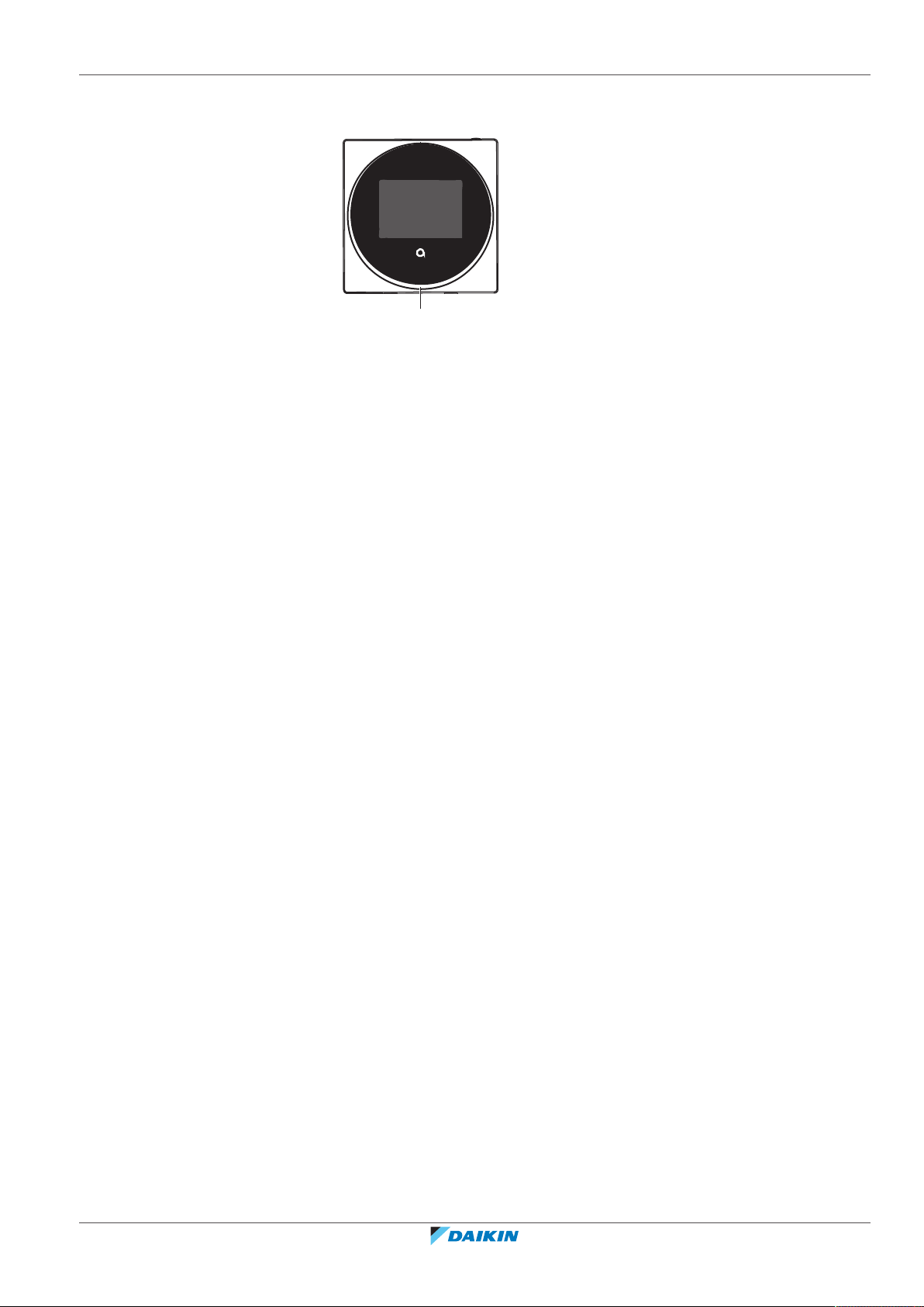
4.4 Status indicator
+
-
a
4 | Remote controller: Overview
a Status indicator
BRC1H82W+K+S
Madoka wired remote controller
4P596268-1 – 2020.12
Installer and user reference guide
15
5 | Operation
19
5 Operation
In this chapter
5.1 Basic usage.............................................................................................................................................................................. 16
5.1.1 Home screen .......................................................................................................................................................... 16
5.1.2 Main menu ............................................................................................................................................................. 17
5.2 Operation mode ..................................................................................................................................................................... 18
5.2.1 About the operation modes................................................................................................................................... 19
5.2.2 To set the operation mode .................................................................................................................................... 23
5.3 Setpoint................................................................................................................................................................................... 23
5.3.1 About the setpoint ................................................................................................................................................. 24
5.3.2 To set the setpoint ................................................................................................................................................. 26
5.4 Date and time ......................................................................................................................................................................... 26
5.4.1 About date and time .............................................................................................................................................. 26
5.4.2 To set date and time .............................................................................................................................................. 27
5.5 Airflow..................................................................................................................................................................................... 27
5.5.1 Airflow direction..................................................................................................................................................... 27
5.5.2 Fan speed ............................................................................................................................................................... 28
5.6 Ventilation............................................................................................................................................................................... 30
5.6.1 Ventilation mode.................................................................................................................................................... 30
5.6.2 Ventilation rate ...................................................................................................................................................... 31
5.7 Advanced usage...................................................................................................................................................................... 31
5.1 Basic usage
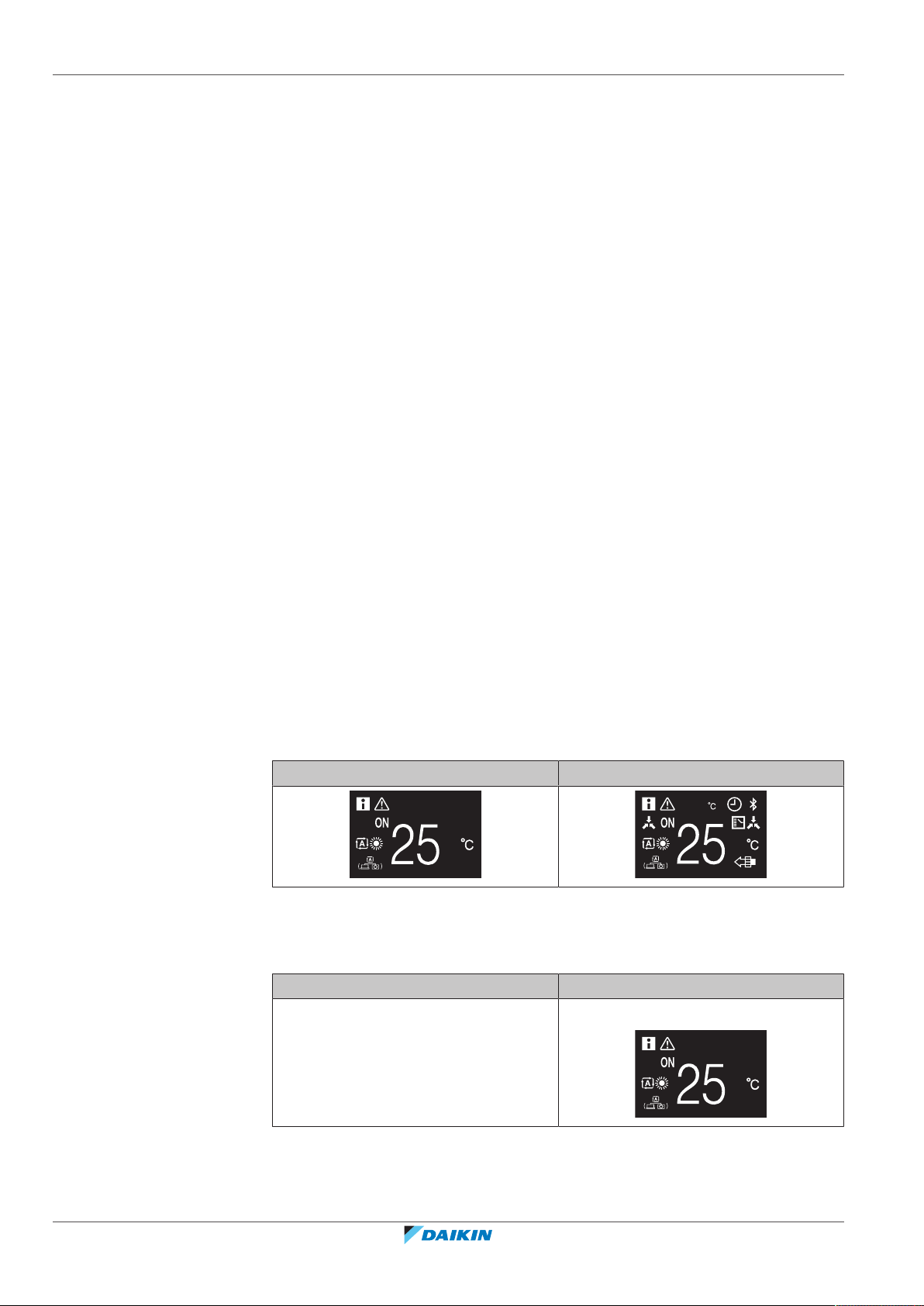
5.1.1 Home screen
Home screen mode
Depending on configuration, the controller either has a standard or a detailed
home screen. While the standard home screen gives you only limited information,
the detailed home screen gives you all kinds of information through status icons.
After a period of operation inactivity, the controller will always revert to the home
screen.
Standard Detailed
Home screen operation
In certain conditions, the controller allows you to perform actions from the home
screen.
Condition Action
Installer and user reference guide
16
The system is running in Cooling,
Heating, or Auto operation mode.
Change the setpoint
BRC1H82W+K+S
Madoka wired remote controller
4P596268-1 – 2020.12
Condition Action
5 | Operation
5.1.2 Main menu
The system is composed of ONLY heat
reclaim ventilation units.
INFORMATION
▪ Depending on configuration, the home screen displays the setpoint either as a
numerical value, or as a symbol. For more information, see "About the
setpoint"[424].
▪ In case the home screen displays the setpoint as a symbol, then it will only display
the status icons of the standard home screen mode, even when the controller is
in detailed home screen mode.
INFORMATION
The controller is equipped with a power saving function that causes the screen to go
blank after a period of inactivity. To make the screen light up again, press one of the
buttons.
Change the ventilation rate
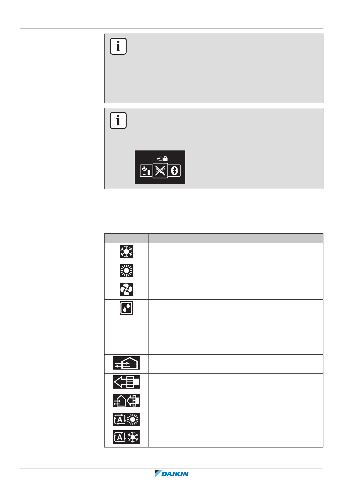
From the home screen, press to enter the main menu. Use and to cycle
through the menus. Press again to enter one of the menus.
Menu Description
Operation mode. Set the operation mode.
Date and time. Make date and time settings.
Airflow direction. Set the indoor unit airflow direction.
Fan speed. Set the indoor unit fan speed.
Ventilation mode. Set the ventilation operation mode.
Ventilation rate. Set the fan speed for ventilation operation.
Bluetooth. Activate Bluetooth to control the system with the
Madoka Assistant app, and/or to perform a remote controller
software update.
BRC1H82W+K+S
Madoka wired remote controller
4P596268-1 – 2020.12
Installer and user reference guide
17
5 | Operation
INFORMATION
▪ Depending on the type of indoor unit you are operating, more or less menus may
be available.
▪ In the main menu, the icon for each menu reflects the current active setting or
mode. When operating the controller, the menu you navigate through can look
different from that represented in this manual.
▪ The controller only allows for basic operation of the system. For advanced
operation (setback, schedule timer, …), see the Madoka Assistant app.
INFORMATION
It is possible that menus are locked. When this is the case, they appear crossed-out
in the main menu, and get accompanied by a lock icon. The locking of functions
happens through the Madoka Assistant app. For more information, see the Madoka
Assistant app and "Function lock"[4114].
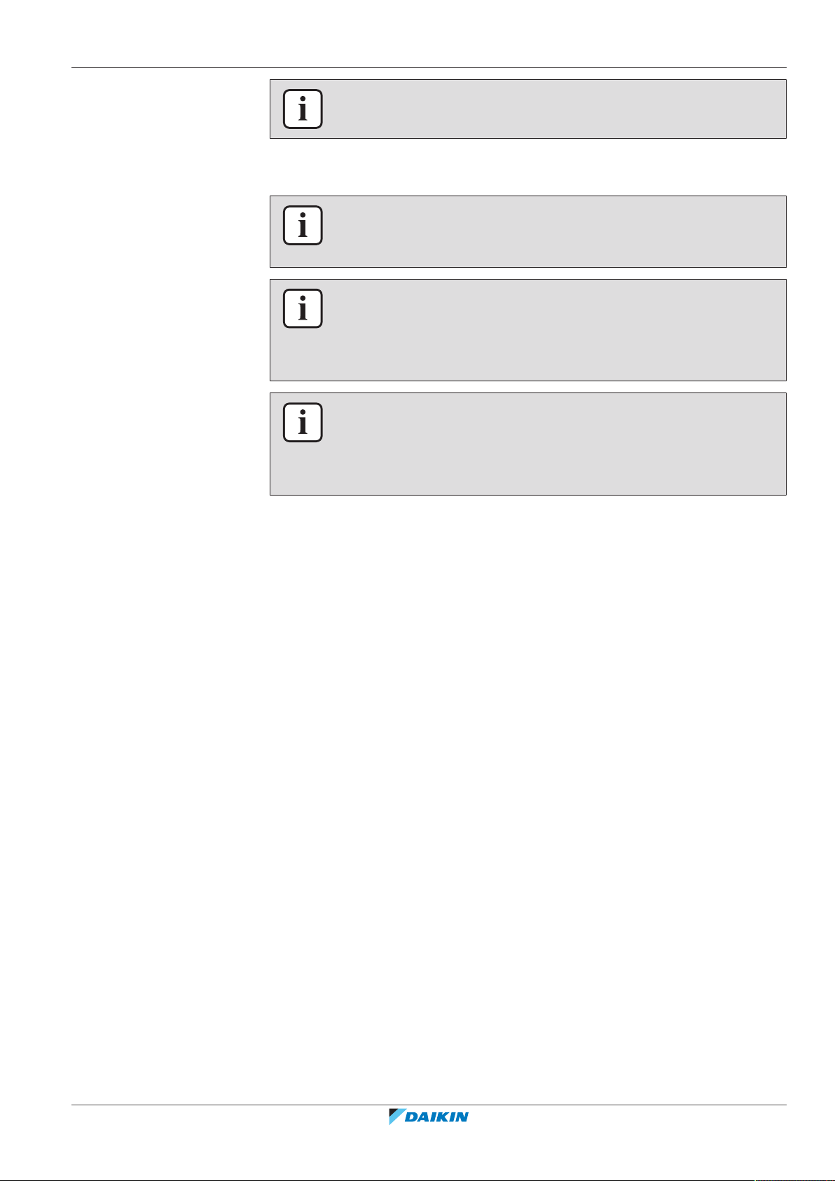
5.2 Operation mode
The indoor unit can operate in various operation modes.
Icon Operation mode
Cooling. In this mode, cooling will be activated as required by the
setpoint, or by Setback operation.
Heating. In this mode, heating will be activated as required by
the setpoint, or by Setback operation.
Fan Only. In this mode, air circulates without heating or cooling.
Dry. In this mode, the air humidity will be lowered with a
minimal temperature decrease.
The temperature and fan speed are controlled automatically and
cannot be controlled by the controller.
Dry operation will not function if the room temperature is too
low.
Ventilation.In this mode, the space gets ventilated, but not
cooled or heated.
Air Clean. In this mode, the optional air cleaning unit operates.
Installer and user reference guide
18
Ventilation + Air Clean. Combination of ventilation and air clean
operation.
Auto. In Auto mode, the indoor unit automatically switches
between heating and cooling mode, as required by the setpoint.
BRC1H82W+K+S
Madoka wired remote controller
4P596268-1 – 2020.12
INFORMATION
Depending on the indoor unit, more or less operation modes are available.
5.2.1 About the operation modes
INFORMATION
If the indoor unit is a cooling-only model, it can only be set to run in Cooling, Fan
only, or Dry operation mode.
INFORMATION
When operation modes are not available in the operation mode menu, it is
additionally possible that they are locked. The locking of operation modes occurs
through the Madoka Assistant app. For more information, see the Madoka Assistant
app and "Function lock"[4114].
INFORMATION
If the operation mode changeover of an indoor unit is under centralised control
('changeover under centralised control' status icon blinking in the home screen),
then it is NOT possible to change the operation mode of that indoor unit. For more
information, see "Cooling/Heating masterhood"[486].
5 | Operation
Cooling
Heating
If the outdoor air temperature is high, it can take some time until the indoor room
temperature reaches the setpoint temperature.
When the indoor room temperature is low, and the indoor unit is set to run in
Cooling operation mode, the indoor unit can enter Defrost operation mode first
(i.e. Heating operation), this to prevent a decrease of the system's cooling capacity
due to frost on the heat exchanger. For more information, see "Heating"[419].
The indoor unit can run in Cooling operation mode because it is operating under
Setback conditions. For more information, see "Setback"[4110].
When running in Heating operation mode, the system requires a longer time to
reach the setpoint temperature than when running in Cooling operation mode. To
make up for this, it is recommended to let the system start operation in advance by
making use of the timer function.
The indoor unit can run in Heating operation mode because it is operating under
Setback conditions. For more information, see "Setback"[4110].
To prevent cold drafts and a reduction of the system's heating capacity, the system
can run in the following special heating operation modes:
BRC1H82W+K+S
Madoka wired remote controller
4P596268-1 – 2020.12
Installer and user reference guide
19
5 | Operation
Operation Description
Defrost To prevent the loss of heating capacity
due to frost accumulation in the outdoor
unit, the system will automatically
switch to defrost operation.
During defrost operation, the indoor
unit fan will stop operation, and the
following icon will appear on the home
screen:
The system will resume normal
operation after approximately 6 to 8
minutes.
Hot start (VRV only) During hot start, the indoor unit fan will
stop operation, and the following icon
will appear on the home screen:
Dry
INFORMATION
When the system is stopped while the indoor unit is running in Heating operation
mode, the fan will continue to operate for approximately 1 minute, this to get out
any heat remaining in the indoor unit.
INFORMATION
▪ The lower the outdoor air temperature, the lower the heating capacity. If the
system's heating capacity is insufficient, it is recommended to include another
heating appliance into the setup (if you use a combustion appliance, ventilate the
room regularly. Also, do not use the heating appliance in places where it is
exposed to the airflow of the indoor unit).
▪ The indoor unit is of the hot air circulation type. As a result, after operation start,
it takes the indoor unit some time to warm up the room.
▪ The indoor unit fan will automatically operate until the indoor temperature of the
system rises to a certain level.
▪ When hot air stays under the ceiling and your feet feel cold, it is recommended to
include a circulator into the setup.
NOTICE
To prevent water leakage or system failure, do NOT turn off the system immediately
after indoor unit operation. Before turning off the system, wait until the drain pump
finishes discharging any water remaining in the indoor unit (approximately 1minute).
Installer and user reference guide
20
INFORMATION
To ensure a smooth start, do not turn off the system while it is operating.
BRC1H82W+K+S
Madoka wired remote controller
4P596268-1 – 2020.12
Auto
0.5°C
~
2°C
0.5°C
~
2°C
0.5°C
~
2°C
0.5°C
~
2°C
C2
+ C1
SP
+ C1
C2
0.5°C
~
2°C
0.5°C
~
2°C
0.5°C
~
2°C
0.5°C
~
2°C
DIFF
C2
+ C1
SP
+ C1
C2
SP
5 | Operation
INFORMATION
In case of indoor unit setpoint logic, the system cannot run in Auto operation mode.
Therefore, to allow for Auto operation mode, go for remote controller setpoint logic.
For more information, see the Madoka Assistant app and "Setpoint logic"[4109].
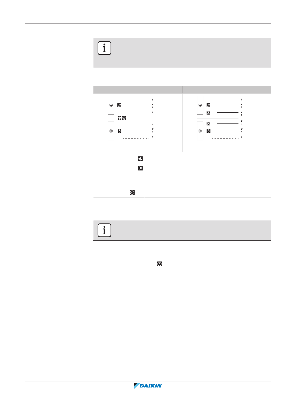
The Auto operation mode logic depends on the set setpoint logic (Madoka
Assistant app setting).
Single setpoint Dual setpoint
Cooling setpoint
Heating setpoint
DIFF Minimum setpoint differential between the Heating and
the Cooling setpoint
+C1 Changeover setpoint (with guard timer)
C2 Forced changeover setpoint
0.5°C~2°C Field settable temperature intervals between setpoints
INFORMATION
The default value of the settable temperature range (0.5°C~2°C) is 0.5°C.
A changeover from the one operation mode to the other occurs in the following
cases:
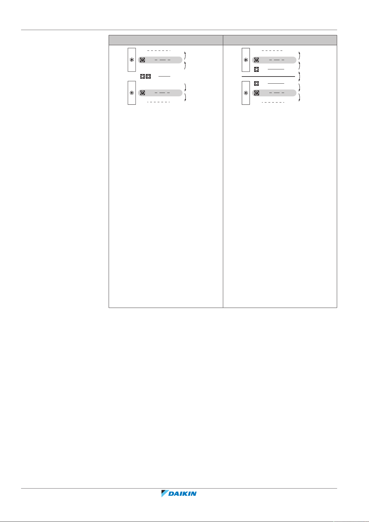
Case 1: primary changeover ( +C1)
A changeover occurs from the moment the room temperature rises above/drops
below the Cooling/Heating changeover setpoint (C1), and the guard timer has run
out.
Example:
BRC1H82W+K+S
Madoka wired remote controller
4P596268-1 – 2020.12
Installer and user reference guide
21
5 | Operation
C2
+ C1
SP
+ C1
C2
+1°C
-1°C
-1°C
+1°C
24°C
23°C
21°C
20°C
22°C
+1°C
+1°C
-1°C
-1°C
DIFF: 2°C
C2
+ C1
SP
+ C1
C2
SP
26°C
25°C
24°C
21°C
20°C
22°C
Single setpoint Dual setpoint
The system is heating up the room.
When after a while the room
temperature rises above C1 (23°C), a
changeover from Heating to Cooling
occurs, provided that the guard timer
has run out. If the guard timer has not
run out, the changeover will only occur
from the moment the timer does run
out. As a result of the changeover, the
guard timer starts running again so as to
allow for or prevent the next
changeover.
The system is cooling down the room.
When after a while the room
temperature drops below C1 (21°C), a
changeover from Cooling to Heating
occurs, provided that the guard timer
has run out. If the guard timer has not
run out, the changeover will only occur
from the moment the timer does run
out. As a result of the changeover, the
guard timer starts running again, to
allow for or prevent the next
changeover.
The system is heating up the room.
When after a while the room
temperature rises above C1 (25°C), a
changeover from Heating to Cooling
occurs, provided that the guard timer
has run out. If the guard timer has not
run out, the changeover will only occur
from the moment the timer does run
out. As a result of the changeover, the
guard timer starts running again so as to
allow for or prevent the next
changeover.
The system is cooling down the room.
When after a while the room
temperature drops below C1 (21°C), a
changeover from Cooling to Heating
occurs, provided that the guard timer
has run out. If the guard timer has not
run out, the changeover will only occur
from the moment the timer does run
out. As a result of the changeover, the
guard timer starts running again, to
allow for or prevent the next
changeover.
Installer and user reference guide
22
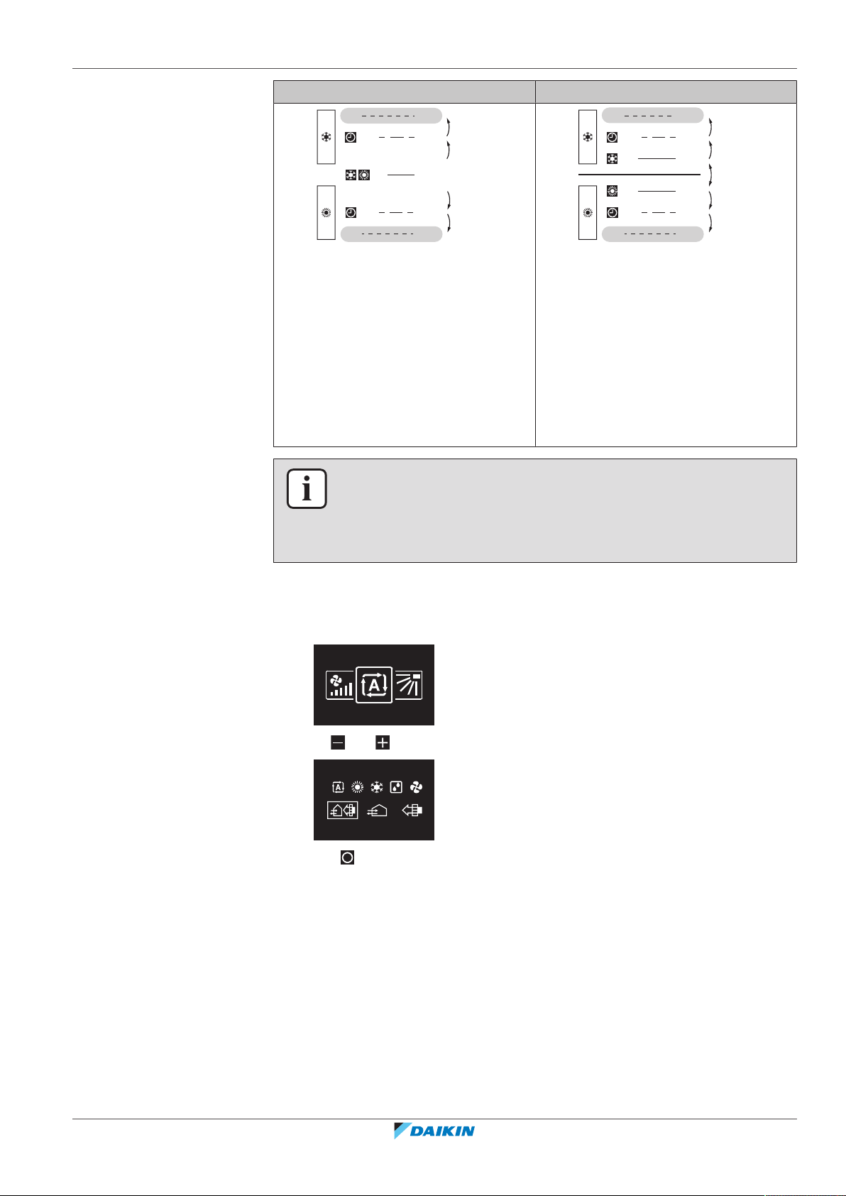
Case 2: forced changeover (C2)
A changeover is forced from the moment the room temperature rises above/drops
below the Cooling/Heating forced changeover setpoint (C2) while the guard timer
is still running.
Example:
BRC1H82W+K+S
Madoka wired remote controller
4P596268-1 – 2020.12
5 | Operation
C2
+ C1
SP
+ C1
C2
+1°C
-1°C
-1°C
+1°C
24°C
23°C
21°C
20°C
22°C
+1°C
+1°C
-1°C
-1°C
DIFF: 2°C
C2
+ C1
SP
+ C1
C2
SP
26°C
25°C
24°C
21°C
20°C
22°C
Single setpoint Dual setpoint
The system is heating up the room.
When the room temperature rises
above C2 (24°C) while the guard timer is
still running, a changeover is forced
from Heating to Cooling.
The system is cooling down the room.
When the room temperature drops
below C2 (20°C) while the guard timer is
still running, a changeover is forced
from Cooling to Heating.
5.2.2 To set the operation mode
1 Navigate to the operation mode menu.
The system is heating up the room.
When the room temperature rises
above C2 (26°C) while the guard timer is
still running, a changeover is forced
from Heating to Cooling.
The system is cooling down the room.
When the room temperature drops
below C2 (20°C) while the guard timer is
still running, a changeover is forced
from Cooling to Heating.
INFORMATION
To prevent operation mode changeovers from occurring too frequently, changeovers
typically occur only after the guard timer has run out (i.e. Case 1). However, to
prevent the room from getting too hot or too cold, a changeover is forced when the
room temperature reaches C2 while the guard timer is still running (i.e. Case 2).
2 Use and to select an operation mode.
3 Press to activate.
Result: The indoor unit changes its operation mode and the controller returns to
the home screen.
5.3 Setpoint
The setpoint is the target temperature for the Cooling, Heating, and Auto
operation modes.
BRC1H82W+K+S
Madoka wired remote controller
4P596268-1 – 2020.12
Installer and user reference guide
23
5 | Operation
28°C
+3°C
-3°C
25°C
22°C
5.3.1 About the setpoint
INFORMATION
The lower setpoint limit of the Cooling operation mode is 20°C, as per UAE Federal
regulation UAE.S 5010-5:2016 clause 6, and UAE.S 5010-1:2016 clause 10.
Depending on configuration, the home screen displays the temperature setpoint
either as a numerical value, or as a symbol.
INFORMATION
For how to set the home screen setpoint, see the Madoka Assistant app. Also see
"Screen"[4104].
Home screen setpoint: Numerical
In case the home screen displays the temperature setpoint as a numerical value,
you control the room temperature by raising or lowering the setpoint by 1°C
increments.
The default setpoint range is 16°C~32°C. If any limitations are set to this range with
the setpoint range function (Madoka Assistant app function; see "Setpoint
range"[4112]), it is only possible to raise or lower the setpoint up/down to the set
maximum/minimum setpoint range limits.
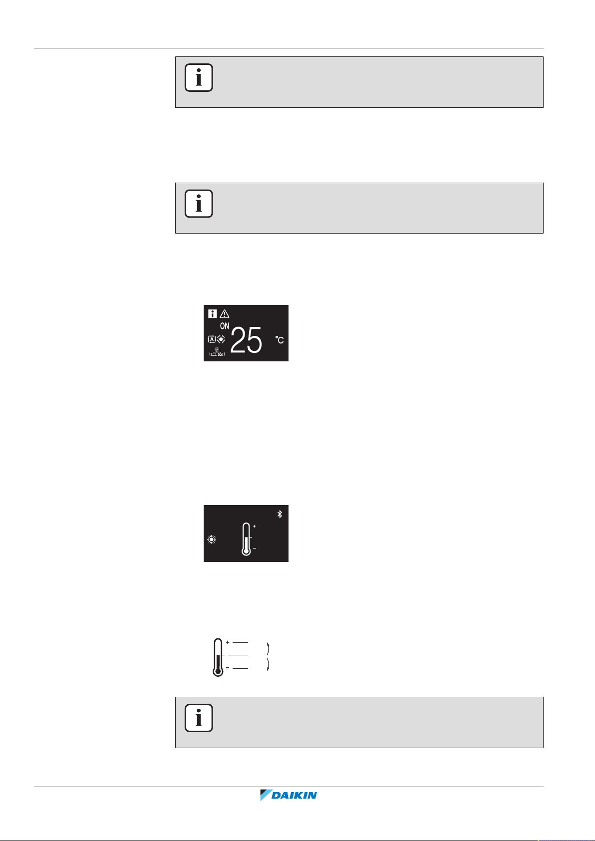
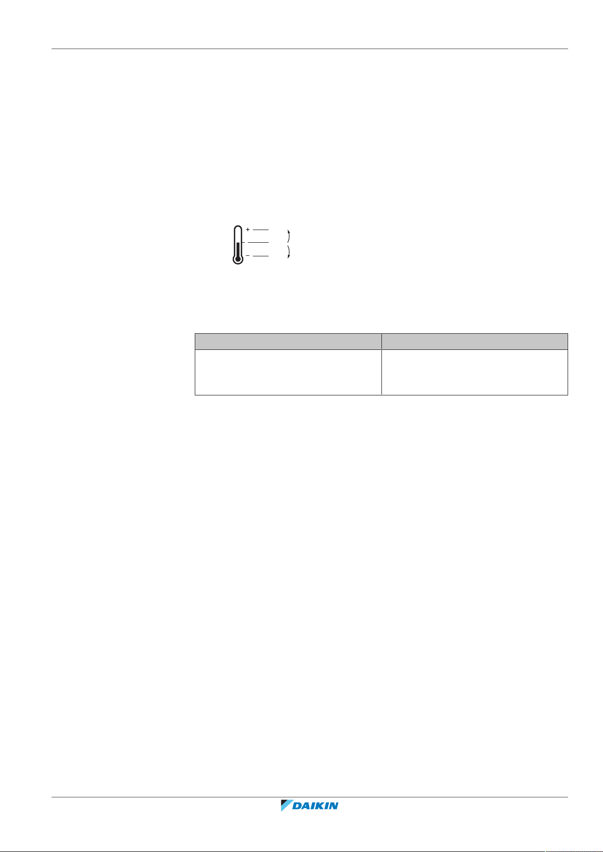
Home screen setpoint: Symbolic
In case the home screen displays the temperature setpoint as a symbol, you
control the room temperature by raising or lowering the setpoint in relation to the
"reference setpoint" (visually indicated by the marker in the middle of the
thermometer).
It is possible to raise the setpoint up to three steps of 1°C above and up to three
steps of 1°C below the reference setpoint.
Example: if the reference setpoint is 25°C, it is possible to raise the setpoint to
28°C and lower it to 22°C.
Installer and user reference guide
24
INFORMATION
For how to set the reference setpoint, see the Madoka Assistant app. Also see
"Screen"[4104].
Exceptions to this logic are possible in case of:
BRC1H82W+K+S
Madoka wired remote controller
4P596268-1 – 2020.12
5 | Operation
28°C
+3°C
-2°C
25°C
23°C
▪ Setpoint range limitations
▪ Central control / control by a schedule
Setpoint range
If any limitations are set to the default setpoint range (16°C~32°C) with the
setpoint range function (Madoka Assistant app function; see "Setpoint
range"[4112]), it is only possible to raise or lower the setpoint up/down to the set
upper/lower setpoint range limits.
Example: if the reference temperature is 25°C, you can normally lower the
setpoint three steps to 22°C. However, if a setpoint range limit is set to 23°C, you
can only lower the setpoint to 23°C.
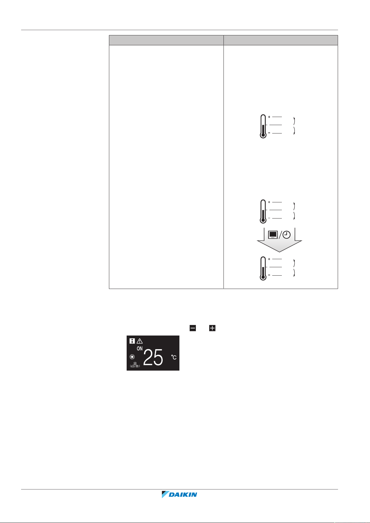
Central control / Schedule
If the system is under the control of a centralised controller or a schedule, then the
regular +3°C/–3°C setpoint range limits can get overruled AND changed.
IF THEN
The centralised controller or schedule
imposes a setpoint that is within the
regular +3°C/–3°C setpoint range.
Nothing unusual happens and the
system follows the regular setpoint and
setpoint range logic.
BRC1H82W+K+S
Madoka wired remote controller
4P596268-1 – 2020.12
Installer and user reference guide
25
5 | Operation
28°C
+3°C
-3°C
25°C
22°C
28°C
+3°C
-3°C
25°C
22°C
27°C
+3°C
-3°C
24°C
21°C
21°C
IF THEN
The centralised controller or schedule
imposes a setpoint that exceeds the
regular +3°C/–3°C setpoint range.
The imposed setpoint becomes the new
upper/lower limit of the +3°C/–3°C
range, and the whole range shifts in
relation to this new limit.
Example: the reference setpoint is set
to 25°C, yielding the following setpoint
range:
If the centralised controller or schedule
changes the setpoint to 21°C, which is
below the range, then "21°C" becomes
the new lower limit, and the range
shifts in relation to this new limit.
5.3.2 To set the setpoint
5.4 Date and time
5.4.1 About date and time
Prerequisite: The active operation mode is either 'Cooling', 'Heating', or 'Auto'.
1 In the home screen, use and to adjust the setpoint.
Result: The indoor unit changes its temperature setpoint.
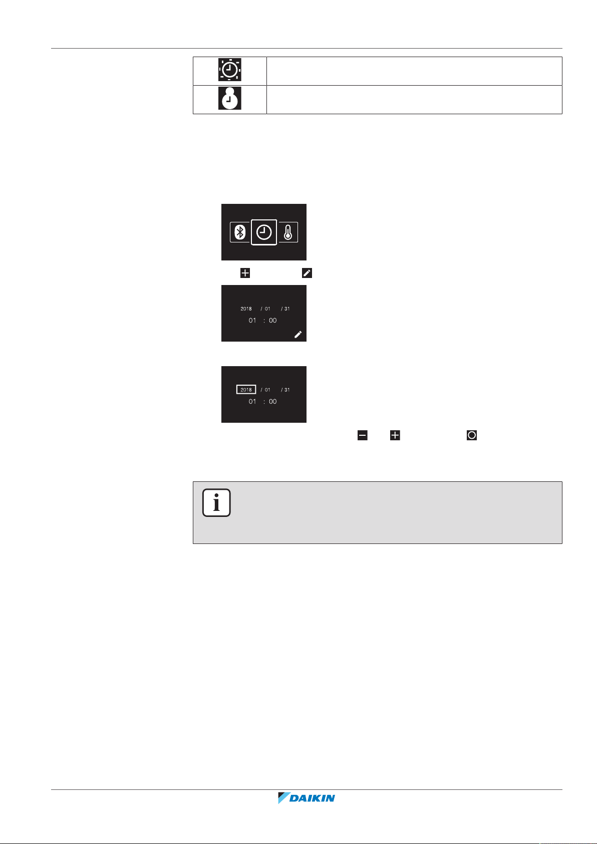
Set the date and time for the indoor units connected to the controller.
Depending on daylight saving time settings, the date and time menu has the
following daylight saving time indicators:
Installer and user reference guide
26
Madoka wired remote controller
BRC1H82W+K+S
4P596268-1 – 2020.12
For more information, see "Indoor unit field settings" [4 73] (remote controller
settings) and "Date and time"[4105] (app settings).
5.4.2 To set date and time
1 Navigate to the date and time menu.
2 Press to activate .
5 | Operation
Summer time
Winter time
Result: You set the date and the time.
5.5 Airflow
5.5.1 Airflow direction
The airflow direction is the direction in which the indoor unit blows its air.
Result: The fields become editable.
3 Set the date and time. Set with and . Confirm with . Cycle through the
menu until all fields are set correctly.
INFORMATION
Confirming the value in a field will automatically bring you to the next field. To finish
making settings and leave the menu, navigate to and confirm the value in the last
field.
About airflow direction
BRC1H82W+K+S
Madoka wired remote controller
4P596268-1 – 2020.12
The following airflow directions can be set:
Installer and user reference guide
27
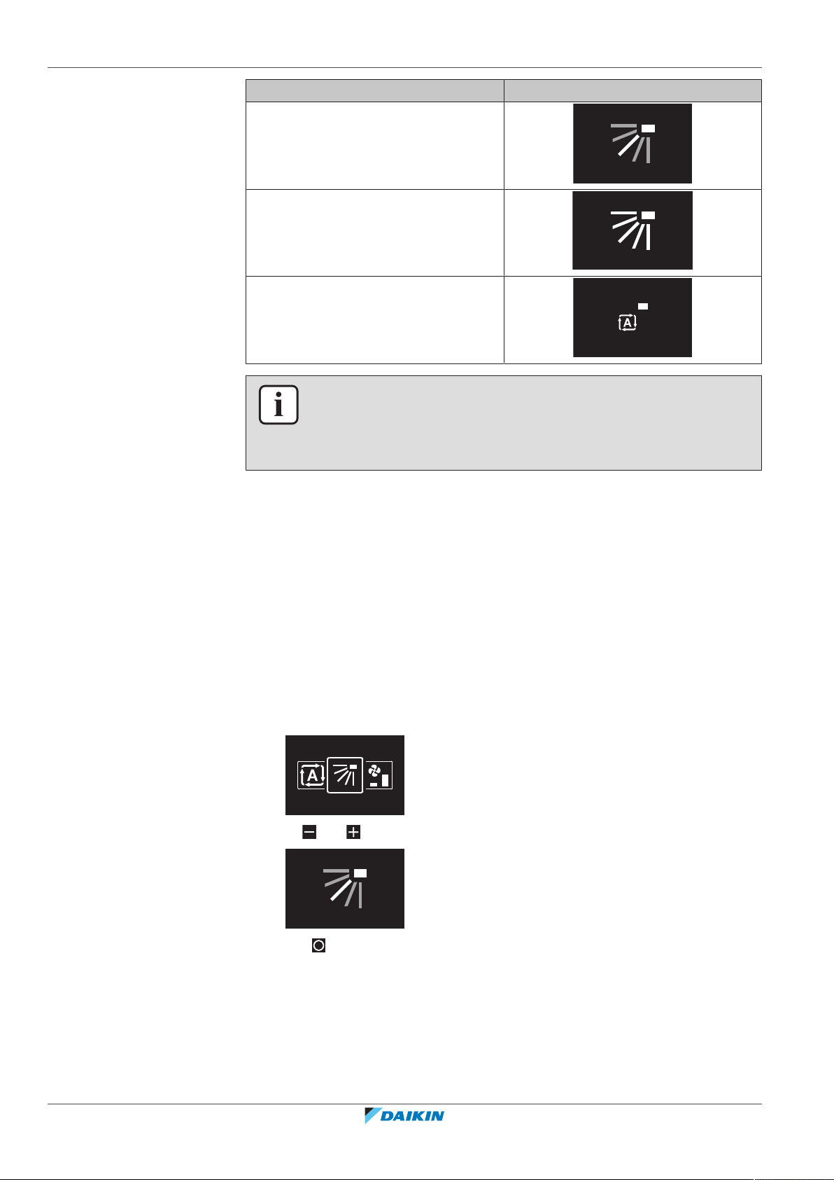
5 | Operation
Direction Screen
Fixed position. The indoor unit blows air
in 1 of 5 fixed positions.
Swing. The indoor unit alternates
between the 5 positions.
Auto. The indoor unit adjusts its airflow
direction according to movement sensed
by a movement sensor.
INFORMATION
▪ Depending on the type of indoor unit, and/or on system layout and organisation,
Auto airflow direction may not be available.
▪ For some types of indoor unit, you cannot set the airflow direction.
Automatic airflow control
In the following operating conditions, the airflow direction of the indoor units is
controlled automatically:
▪ When the room temperature is higher than the controller's setpoint for Heating
operation (including Auto operation).
▪ When the indoor units run in Heating operation mode, and the Defrost function
is active.
▪ When the indoor units run in Continuous operation, and the airflow direction is
Horizontal.
To set the airflow direction
1 Navigate to the airflow direction menu.
2 Use and to adjust the airflow direction.
5.5.2 Fan speed
Installer and user reference guide
28
3 Press to confirm.
Result: The indoor unit changes its airflow direction and the controller returns to
the home screen.
The fan speed is the strength of the airflow coming out of the indoor unit.
BRC1H82W+K+S
Madoka wired remote controller
4P596268-1 – 2020.12
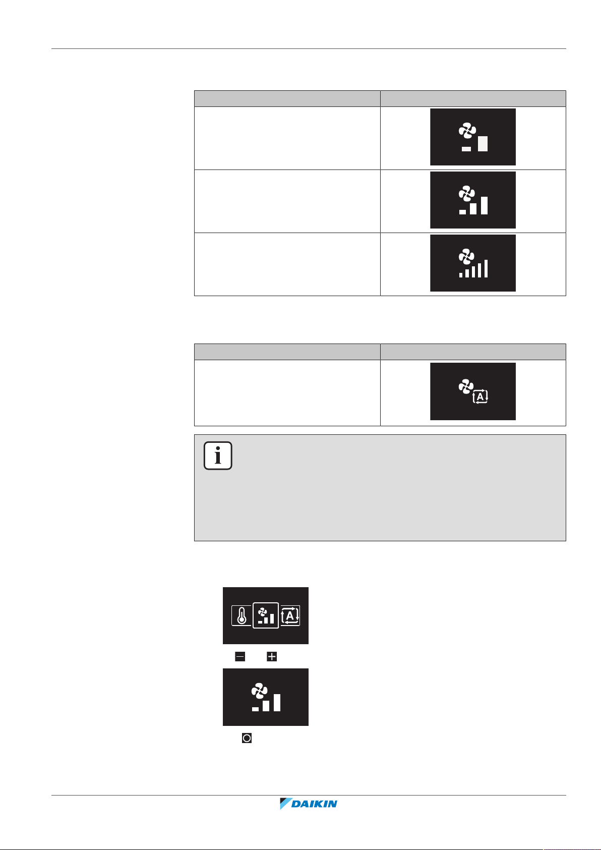
About fan speed
5 | Operation
Depending on the indoor unit, you can choose between either:
Fan speed Screen
2 fan speeds
3 fan speeds
5 fan speeds
Some indoor units additionally support Automatic fan speed. In this case, the
indoor unit adjusts its fan speed automatically, according to the setpoint and
indoor temperature.
Automatic
To set the fan speed
1 Navigate to the fan speed menu.
Fan speed Screen
INFORMATION
▪ For mechanical protection purposes, it is possible that the indoor unit switches
itself to 'Automatic fan speed' mode.
▪ If the fan stops operating, this does not necessarily mean system failure. The fan
can stop operating at all times.
▪ It may take some time before changes made to fan speed settings are actually
carried out.
BRC1H82W+K+S
Madoka wired remote controller
4P596268-1 – 2020.12
2 Use and to adjust the fan speed.
3 Press to confirm.
Result: The indoor unit changes its fan speed and the controller returns to the
home screen.
Installer and user reference guide
29
5 | Operation
5.6 Ventilation
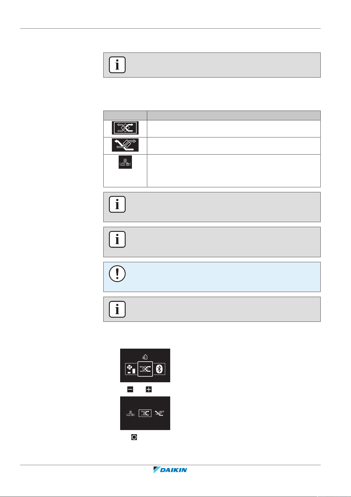
5.6.1 Ventilation mode
INFORMATION
Ventilation settings can ONLY be made for heat reclaim ventilation units.
The heat reclaim ventilation unit can operate in various operation modes.
Icon Ventilation mode
Energy Reclaim Ventilation. The outdoor air is supplied to the
room after passing through a heat exchanger.
Bypass. The outdoor air is supplied to the room without passing
through a heat exchanger.
Auto. To ventilate the room in the most efficient way, the heat
reclaim ventilation unit automatically switches between "Bypass"
and "Energy Reclaim Ventilation" mode (based on internal
calculations).
To set the ventilation mode
1 Navigate to the ventilation mode menu.
INFORMATION
Depending on the heat reclaim ventilation unit, more or less ventilation modes are
available.
INFORMATION
Ventilation mode changes are possible regardless of Cooling/Heating masterhood.
For more information, see "Cooling/Heating masterhood"[486].
NOTICE
Before starting up the system, the unit MUST be energised for at least 6 hours to
avoid compressor breakdown during startup.
INFORMATION
To ensure a smooth start, do not turn off the system while it is operating.
Installer and user reference guide
30
2 Use and to select a ventilation mode.
3 Press to activate.
Result: The heat reclaim ventilation unit changes its operation mode and the
controller returns to the home screen.
BRC1H82W+K+S
Madoka wired remote controller
4P596268-1 – 2020.12

5.6.2 Ventilation rate
To set the ventilation rate
5 | Operation
The ventilation rate is the fan speed during ventilation operation.
1 Navigate to the ventilation rate menu.
2 Use and to adjust the ventilation rate.
3 Press to confirm.
Result: The heat reclaim ventilation unit changes its ventilation rate and the
controller returns to the home screen.
5.7 Advanced usage
The controller only allows for basic operation. For advanced operation, use the
Madoka Assistant app.
INFORMATION
To operate the controller with the app, you need to connect the controller to a
mobile device on which the app is installed. For instructions, see
"15.2Pairing"[493].
BRC1H82W+K+S
Madoka wired remote controller
4P596268-1 – 2020.12
Installer and user reference guide
31

6 | Maintenance and service
6 Maintenance and service
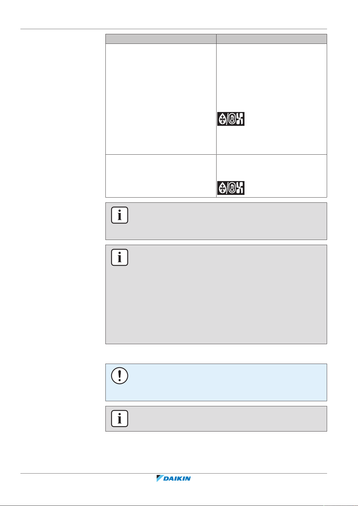
6.1 Overview: Maintenance and service
When a system components needs maintenance or service, consult your dealer. To
indicate that maintenance is due, the controller displays on the home screen,
and/or displays a warning screen as soon as you press to enter the main menu
from the home screen.
The following warning screens are related to indoor unit maintenance:
Clean the indoor unit filter Replace the indoor unit filter
Empty the indoor unit dustbox —
Installer and user reference guide
32
Madoka wired remote controller
BRC1H82W+K+S
4P596268-1 – 2020.12

7 Troubleshooting
CH-02
1234
In this chapter
7.1 Overview: Troubleshooting .................................................................................................................................................... 33
7.2 Refrigerant leak detection...................................................................................................................................................... 33
7.2.1 About refrigerant leak detection ........................................................................................................................... 33
7.2.2 To stop the leak detection alarm ........................................................................................................................... 34
7.1 Overview: Troubleshooting
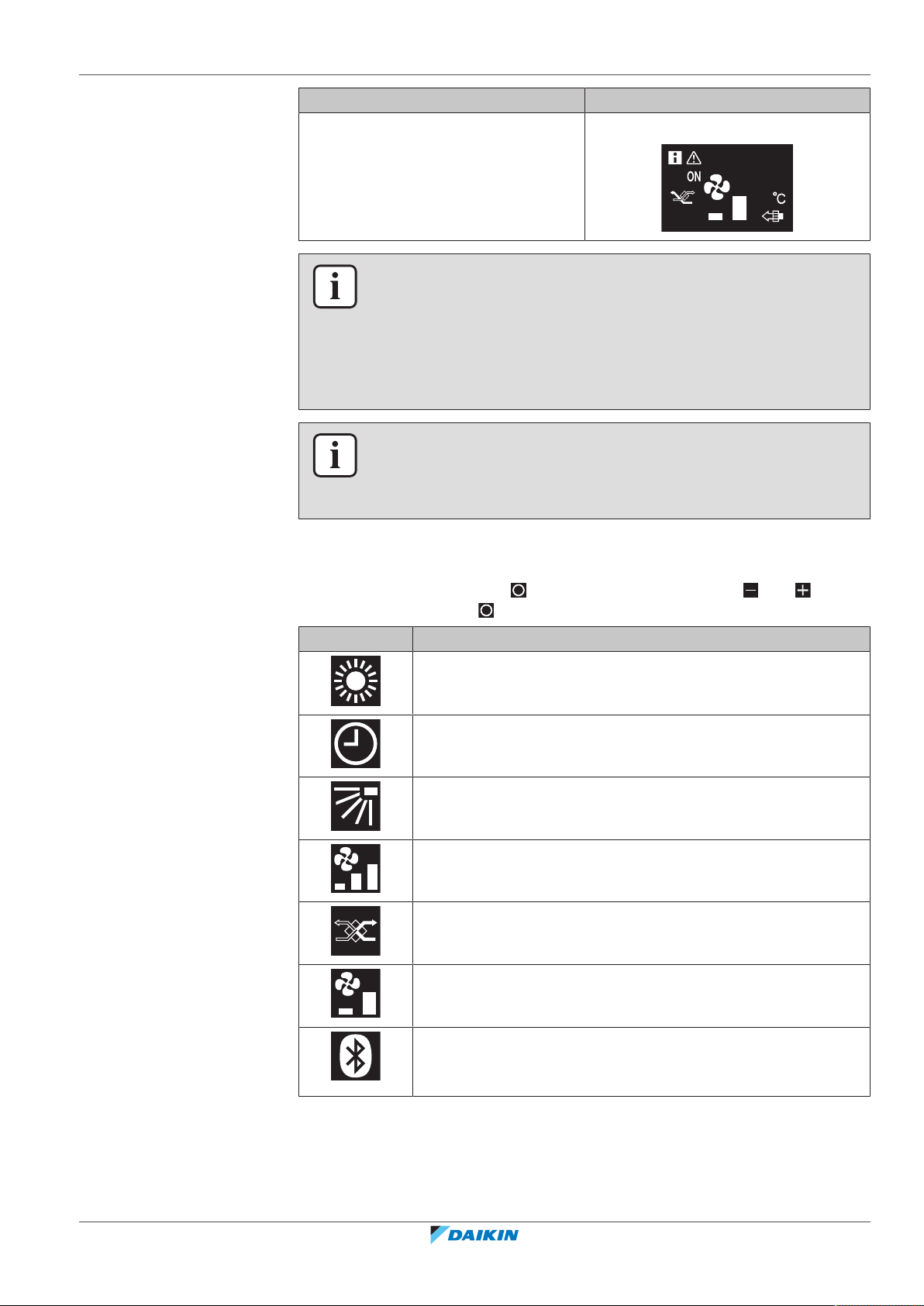
When the system is in error, consult your dealer. To indicate system error, the
controller displays on the home screen, and/or displays an error screen as soon
as you press to enter the main menu from the home screen.
7 | Troubleshooting
Error screen (example)
INFORMATION
If the controller is set to be operable in "Supervisor" mode, then the controller adds
the "supervised room address" of the faulty indoor unit to the error screen. In
“Supervisor” mode, it is mandatory to set a unique “supervised room address” for
every indoor unit. The “supervised room address” can be set in the Madoka Assistant
app. Note that in case of multiple leakages, only the address of the first faulty unit
rising the error is displayed.
For more information about the modes the controller can be set to be operable in,
see "4.1About the controller"[412].
7.2 Refrigerant leak detection
When the system detects a refrigerant leak, an alarm goes off. Stop the alarm and
consult your dealer.
INFORMATION
For more information on what to do in the app in case of a refrigerant leak, see
"15About the app"[492].
BRC1H82W+K+S
Madoka wired remote controller
4P596268-1 – 2020.12
7.2.1 About refrigerant leak detection
The information that the controller displays in case of a refrigerant leak depends
on the mode that the controller is set to be operable in.
Installer and user reference guide
33

7 | Troubleshooting
A0-11
Unit 00
A0-11A0-11
A0-11
1234
A0-11
Unit 00
A0-11
Unit 00
Normal and Alarm only mode
Master controller Slave controller
The controller displays the unit number
of the leaking indoor unit
Supervisor mode
Master controller Slave controller
INFORMATION
For more information about the modes, see "4.1About the controller"[412].
7.2.2 To stop the leak detection alarm
The controller does not display the unit
number of the leaking indoor unit
— The controller displays the supervised
room address of the leaking indoor unit
1 Press for 3 seconds to stop the alarm.
Result: The alarm stops.
2 Consult your dealer.
INFORMATION
In case the controller is set to be operable in ‘Supervisor’ mode, the controller will
indicate the supervised room address of the indoor unit for which the leak detection
alarm occurs. However, it is not possible to stop the alarm of the indoor unit
controller (set to be operable in either “Normal” or “Alarm only” mode) from the
controller in “Supervisor” mode. The alarm of the controller connected to the indoor
unit with the leak has to be stopped individually.
Installer and user reference guide
34
Madoka wired remote controller
BRC1H82W+K+S
4P596268-1 – 2020.12

For the installer
For the installer
BRC1H82W+K+S
Madoka wired remote controller
4P596268-1 – 2020.12
Installer and user reference guide
35

8 | About the box
a b
1× 2×
8 About the box
8.1 To unpack the controller
1 Open the box.
2 Separate the accessories.
a Installation and operation manual
b Wood screws + wall plugs (Ø4.0×30)
Installer and user reference guide
36
Madoka wired remote controller
BRC1H82W+K+S
4P596268-1 – 2020.12

9 Preparation
10 mm
L
9.1 Wiring requirements
All wiring must comply with the following requirements:
Wire specification Value
Type Sheathed vinyl cord or cable (2 wires)
Section 0.75~1.25 mm
Maximum length 500 m
9.1.1 To prepare the wiring for installation
1 Peel the sheath of the part of the cable that needs to pass through the inside
of the rear casing (L), according to the figure and the table.
2 Keep a 10mm distance between the length of the 2 wires.
9 | Preparation
2
Wiring outlet L
Top ±150mm
Left ±120mm
Bottom ±100mm
Rear No requirements
BRC1H82W+K+S
Madoka wired remote controller
4P596268-1 – 2020.12
Installer and user reference guide
37

10 | Installation
a
b
c
10 Installation
In this chapter
10.1 Overview: Installation
10.1 Overview: Installation ............................................................................................................................................................. 38
10.2 Mounting the controller ......................................................................................................................................................... 38
10.2.1 About mounting the controller.............................................................................................................................. 38
10.2.2 To mount the controller......................................................................................................................................... 39
10.3 Connecting the electrical wiring............................................................................................................................................. 40
10.3.1 Precautions when connecting the electrical wiring .............................................................................................. 40
10.3.2 To connect the electrical wiring............................................................................................................................. 40
10.4 Closing the controller ............................................................................................................................................................. 41
10.4.1 Precautions when closing the controller............................................................................................................... 41
10.4.2 To close the controller........................................................................................................................................... 41
10.5 Opening the controller ........................................................................................................................................................... 42
10.5.1 Precautions when opening the controller............................................................................................................. 42
10.5.2 To open the controller........................................................................................................................................... 42
The installation of the controller typically consists of the following stages:
1 Determining how you want to route the electrical wiring, and nipping away a
piece of the rear casing accordingly.
2 Mounting the rear casing to the wall.
3 Connecting the electrical wiring.
4 Closing the controller.
10.2 Mounting the controller
10.2.1 About mounting the controller
Before you can mount the controller, you have to determine the wiring routing,
and accordingly, remove a piece of the controller's rear casing.
The wiring can be routed from the top, the rear, the left, or the bottom. Remove a
piece of the rear casing according to the illustration:
Installer and user reference guide
38
a Wiring from the top
b Wiring from the left
c Wiring from the bottom
BRC1H82W+K+S
Madoka wired remote controller
4P596268-1 – 2020.12

In case you are routing the wiring from the rear, you do not have to remove
anything.
10.2.2 To mount the controller
1 Take the screws and plugs from the accessory bag.
2 Mount the rear casing to a flat surface.
10 | Installation
INFORMATION
When routing the wiring from the top or from the rear, insert the wiring through the
knockout hole before mounting the rear casing to the wall.
INFORMATION
If required (e.g. when mounting to a flush-mounted electrical installation box),
mount the rear casing by way of the knockout holes.
NOTICE
When mounting the rear casing to a flush-mounted electrical installation box inside a
wall, make sure that that wall is completely flat.
NOTICE
Be careful not to distort the rear casing by overtightening the mounting screws.
BRC1H82W+K+S
Madoka wired remote controller
4P596268-1 – 2020.12
Installer and user reference guide
39

10 | Installation
P1P2
10.3 Connecting the electrical wiring
10.3.1 Precautions when connecting the electrical wiring
INFORMATION
Also read the precautions and requirements in the following chapters:
▪ General safety precautions
▪ Preparation
WARNING
All field wiring and components MUST be installed by a licensed electrician and
MUST comply with the applicable legislation.
CAUTION
When connecting the controller to the indoor unit, make sure the indoor unit
switchbox and transmission wiring are not connected.
NOTICE
The wiring for connection is NOT included.
NOTICE
When wiring, run the wiring away from the power supply wiring in order to avoid
receiving electric noise (external noise).
INFORMATION
P1 and P2 have no polarity.
10.3.2 To connect the electrical wiring
Connect controller terminals P1/P2 to indoor unit terminals P1/P2.
From the top
Installer and user reference guide
40
BRC1H82W+K+S
Madoka wired remote controller
4P596268-1 – 2020.12

From the rear
P1P2
P1P2
P1P2
From the left
10 | Installation
From the bottom
10.4 Closing the controller
10.4.1 Precautions when closing the controller
CAUTION
Never touch the internal parts of the controller.
CAUTION
When closing the controller, be careful not to pinch the wiring.
10.4.2 To close the controller
BRC1H82W+K+S
Madoka wired remote controller
4P596268-1 – 2020.12
NOTICE
To prevent damage, make sure the front of the controller is clicked into the rear
casing securely.
1 Click the front of the controller into the rear casing.
Installer and user reference guide
41

10 | Installation
1
2
10.5 Opening the controller
10.5.1 Precautions when opening the controller
2 When the installation site is dust‑free, peel off the protective seal.
10.5.2 To open the controller
1 Insert a flat‑head screwdriver into one of the bottom closing mechanisms and
slowly twist it.
NOTICE
The controller PCB is mounted into the front casing. When opening the controller, be
careful not to damage the PCB.
NOTICE
When the front and rear casing are separated, make sure the PCB does not come
into contact with dust or moisture.
Installer and user reference guide
42
Madoka wired remote controller
BRC1H82W+K+S
4P596268-1 – 2020.12

11 Starting up the system
a
b
c d
CAUTION
Before starting up the system, make sure:
▪ The indoor and outdoor unit wiring is completed.
▪ The switch box covers of the indoor and outdoor units are closed.
The controller gets its power from the indoor unit. It will start up as soon as it is
connected. For the controller to be operable, make sure the indoor unit is powered
on.
Once the controller is powered, it will automatically start up. If it is the first and
only controller that is connected to the indoor unit, it will automatically get
designated as a "Normal" master controller.
11.1 Controller designation
Once started up, designate the controller to be operable in "Normal", "Alarm only",
or "Supervisor" mode, and designate it as either a master or a slave controller. If a
controller is set to be operable in “Supervisor” mode, it can only be a slave
controller.
11 | Starting up the system
a Outdoor unit
b Indoor unit
c Master remote controller
d Slave remote controller
On the information screen, master/slave status is indicated by the following icons:
Icon Description
Master
Slave
For more information, see "Information screen"[452].
INFORMATION
It is only possible to use a master and a slave controller of the same type.
INFORMATION
In case digital input adapter BRP7A5* is part of the system, it is not possible to
connect and designate a second controller. Connecting a second controller when the
system already contains the adapter, will cause the adapter to go in error.
BRC1H82W+K+S
Madoka wired remote controller
4P596268-1 – 2020.12
Installer and user reference guide
43

11 | Starting up the system
11.1.1 To designate a controller as slave
INFORMATION
If the slave controller does not display the home screen two minutes after its
designation, turn off the power and check the wiring.
INFORMATION
After re-designating a controller, the system requires a power reset.
INFORMATION
Slave controllers do not support all functions. If you cannot find a function on a slave
controller, check for it on the master controller.
INFORMATION
For master and slave controllers to function together, they need to have the same
value for the "Home screen setpoint" setting (Madoka Assistant app setting), i.e. all
set to "Numerical" or all set to "Symbolic".
Prerequisite: A master controller is already connected to the indoor unit.
1 Connect a second controller.
Result: It will start up automatically.
2 Wait for a U5 or U8 error to appear on the screen.
3 When the U5 or U8 error appears, press and keep it pressed until "2"
appears on the screen.
Result: The controller is now designated as slave.
Installer and user reference guide
44
Madoka wired remote controller
BRC1H82W+K+S
4P596268-1 – 2020.12

12 | Remote controller: Overview
12 Remote controller: Overview
In this chapter
12.1 About the controller ............................................................................................................................................................... 45
12.1.1 To configure the controller.................................................................................................................................... 46
12.2 Buttons.................................................................................................................................................................................... 46
12.3 Status icons ............................................................................................................................................................................. 47
12.4 Status indicator ....................................................................................................................................................................... 48
12.4.1 Behaviour ............................................................................................................................................................... 48
12.1 About the controller
Depending on configuration, the controller is operable in either one of three
modes. Each mode offers different controller functionality.
Mode Functionality
Normal The controller is fully functional.
All functionality described under
"13Operation"[450] is available.
The controller can be a master or a
slave controller.
Alarm only The controller only acts as leak
detection alarm for a single indoor unit.
No functionality described under
"13Operation"[450] is available.
For information on the leak detection
alarm, see "7.2Refrigerant leak
detection"[433].
The controller can be a master or a
slave controller.
Supervisor The controller only acts as leak
detection alarm for the whole system,
i.e. multiple indoor units and their
respective controllers. This mode is
intended for a controller that is to be
used in a supervision location, e.g. the
reception desk of a hotel.
No functionality described under
"13Operation"[450] is available.
BRC1H82W+K+S
Madoka wired remote controller
4P596268-1 – 2020.12
For information on the leak detection
alarm, see "7.2Refrigerant leak
detection"[433].
The controller can only be a slave
controller.
For more information on how to set the controller to be operable in a specific
mode, see "To configure the controller"[446]. When using “Supervisor” mode, it
is important to set the supervised room address in order to know for which indoor
unit the refrigerant leak alarm occurs. See "Supervised room address"[4123] for
more inormation.
Installer and user reference guide
45

12 | Remote controller: Overview
+
-
c b d
a
12.1.1 To configure the controller
You can configure the controller to be operable in either one of three modes. For
more information about the modes, see "12.1About the controller"[445].
Mode Configuration
Change remote controller field setting:
12.2 Buttons
Normal (default)
Mode: R2
SW: 5
Value: 0
Change remote controller field setting:
Alarm only
Mode: R2
SW: 5
Value: 1
Change remote controller field setting:
Supervisor
Mode: R2
SW: 5
Value: 2
For more information on how to change remote controller field settings, see "Field
settings"[469].
Installer and user reference guide
46
a
ON/OFF
▪ When OFF, press to turn ON the system.
▪ When ON, press to turn OFF the system.
b
ENTER/ACTIVATE /SET
▪ From the home screen, enter the main menu.
▪ From the main menu, enter one of the submenus.
▪ From their respective submenu, activate an operation/ventilation mode.
▪ In one of the submenus, confirm a setting.
c
CYCLE/ADJUST
▪ Cycle left.
▪ Adjust a setting (default: decrease).
d
CYCLE/ADJUST
▪ Cycle right.
▪ Adjust a setting (default: increase).
Madoka wired remote controller
BRC1H82W+K+S
4P596268-1 – 2020.12

12.3 Status icons
12 | Remote controller: Overview
Icon Description
System operation ON. Indicates that the system is in operation.
System operation OFF. Indicates that the system is NOT in
operation.
Bluetooth.
a mobile device, for use with the Madoka Assistant app.
Lock. Indicates that a function or operation mode is locked and
therefore cannot be used or selected.
Centralised control. Indicates that the system is controlled by
central control equipment (optional accessory) and that control
of the system by the controller is limited.
Changeover under centralised control. Indicates that the
cooling/heating changeover is under centralised control by
another indoor unit, or by an optional cool/ heat selector that is
connected to the outdoor unit.
(1)
Indicates that the controller is communicating with
Defrost/Hot start. Indicates that the defrost/hot start mode is
active.
Schedule/Timer. Indicates that the system operates according to
a schedule, or that the OFF timer is enabled.
Time not set. Indicates that controller's time is not set.
Self-cleaning filter operation. Indicates that self-cleaning filter
operation is active.
Quick Start. Indicates that Quick Start mode is active (Sky Air
only).
Test operation. Indicates that Test Operation mode is active (Sky
Air only).
Inspection. Indicates that the indoor or outdoor unit is being
inspected.
Periodic inspection. Indicates that the indoor or outdoor unit is
being inspected.
Backup. Indicates that in the system an indoor unit is set as
backup indoor unit.
Individual airflow direction. Indicates that the individual airflow
direction setting is enabled.
(1)
The Bluetooth® word mark and logos are registered trademarks owned by the Bluetooth SIG, Inc. and use of such marks
by Daikin Europe N.V. is under license. Other trademarks and trade names are those of their respective owners.
BRC1H82W+K+S
Madoka wired remote controller
4P596268-1 – 2020.12
Information. Indicates that the system has a message to convey.
To see the message, go to the information screen.
Warning. Indicates that an error occurred, or that an indoor unit
component needs to be maintained.
Installer and user reference guide
47

12 | Remote controller: Overview
+
-
a
Icon Description
Power consumption limit. Indicates that the system's power
consumption is being limited, and that it is running with
restricted capacity.
End of power consumption limit. Indicates that the system's
power consumption is no longer being limited, and that it is no
longer running with restricted capacity.
Rotation. Indicates that Rotation mode is active.
Setback. Indicates that the indoor unit is operating under
setback conditions.
Ventilation. Indicates that a heat reclaim ventilation unit is
connected.
INFORMATION
▪ For information on the operation mode and ventilation mode icons, see
"13.2Operation mode"[454] and "Ventilation mode"[465] respectively.
▪ Most icons are related to things set in the Madoka Assistant app. For more
information, see the app.
12.4 Status indicator
12.4.1 Behaviour
The behaviour of the status indicator depends on remote controller field setting
R1-11 (status indicator mode). Depending on the value that is set for this setting,
the status indicator has the following behaviour:
Operation state Status indicator behaviour
Operation ON ON ON ON (when the
a Status indicator
0 (Normal) 1 (Hotel setting 1) 2 (Hotel setting 2)
backlight goes into
faint state, the
status indicator
turns OFF)
Installer and user reference guide
48
Operation OFF OFF OFF OFF
Error Blinking (no change) (no change)
BRC1H82W+K+S
Madoka wired remote controller
4P596268-1 – 2020.12

12 | Remote controller: Overview
Operation state Status indicator behaviour
0 (Normal) 1 (Hotel setting 1) 2 (Hotel setting 2)
Warning ON ON ON (when the
backlight goes into
faint state, the
status indicator
turns OFF)
Setting of status
indicator intensity
Pairing with indoor
unit
INFORMATION
Remote controller field setting R1-11 allows for changes to the behaviour of the
status indicator, making the controller suitable for use in hotels.
INFORMATION
By default, the controller is in status indicator mode "Hotel 2".
ON ON ON
Blinking Blinking Blinking
BRC1H82W+K+S
Madoka wired remote controller
4P596268-1 – 2020.12
Installer and user reference guide
49

13 | Operation
13 Operation
In this chapter
13.1 Basic usage.............................................................................................................................................................................. 50
13.1.1 Screen backlight..................................................................................................................................................... 50
13.1.2 Home screen .......................................................................................................................................................... 51
13.1.3 Information screen................................................................................................................................................. 52
13.1.4 Main menu ............................................................................................................................................................. 53
13.2 Operation mode ..................................................................................................................................................................... 54
13.2.1 About the operation modes................................................................................................................................... 54
13.2.2 To set the operation mode.................................................................................................................................... 58
13.3 Setpoint................................................................................................................................................................................... 58
13.3.1 About the setpoint................................................................................................................................................. 59
13.3.2 To set the setpoint................................................................................................................................................. 61
13.4 Date and time ......................................................................................................................................................................... 61
13.4.1 About date and time.............................................................................................................................................. 61
13.4.2 To set date and time .............................................................................................................................................. 62
13.5 Airflow ..................................................................................................................................................................................... 62
13.5.1 Airflow direction..................................................................................................................................................... 62
13.5.2 Fan speed ............................................................................................................................................................... 63
13.6 Ventilation............................................................................................................................................................................... 65
13.6.1 Ventilation mode.................................................................................................................................................... 65
13.6.2 Ventilation rate ...................................................................................................................................................... 66
13.7 Advanced usage ...................................................................................................................................................................... 66
13.1 Basic usage
13.1.1 Screen backlight
For the controller to be operable, the screen backlight needs to be ON. Otherwise,
the controller does not detect any button presses.
After a period of operation inactivity, the backlight will either turn OFF, or go into a
faint ON state, depending on operation conditions:
▪ Operation OFF: backlight OFF;
▪ Operation ON: backlight ON faintly.
To turn ON the backlight
INFORMATION
▪ Backlight state changeover after inactivity is set with remote controller field
setting R1-8 (No-operation timer). For more information, see "Remote controller
field settings"[475].
▪ Backlight faintness is set with remote controller field setting R1-10 (Backlight
faintness). For more information, see "Remote controller field settings"[475].
▪ For instructions on how to set screen brightness and contrast when the backlight
is ON, see "Screen settings"[468].
Installer and user reference guide
50
1 Press shortly.
BRC1H82W+K+S
Madoka wired remote controller
4P596268-1 – 2020.12

+
-
13.1.2 Home screen
19
13 | Operation
Home screen mode
Depending on configuration, the controller either has a standard or a detailed
home screen. While the standard home screen gives you only limited information,
the detailed home screen gives you all kinds of information through status icons.
After a period of operation inactivity, the controller will always revert to the home
screen.
Standard Detailed
Home screen operation
In certain conditions, the controller allows you to perform actions from the home
screen.
Condition Action
The system is running in Cooling,
Change the setpoint
Heating, or Auto operation mode.
The system is composed of ONLY heat
Change the ventilation rate
reclaim ventilation units.
INFORMATION
▪ Depending on configuration, the home screen displays the setpoint either as a
numerical value, or as a symbol. For more information, see "About the
setpoint"[459].
▪ In case the home screen displays the setpoint as a symbol, then it will only display
the status icons of the standard home screen mode, even when the controller is
in detailed home screen mode.
BRC1H82W+K+S
Madoka wired remote controller
4P596268-1 – 2020.12
Installer and user reference guide
51

13 | Operation
a
a
13.1.3 Information screen
INFORMATION
The controller is equipped with a power saving function that causes the screen to go
blank after a period of inactivity. To make the screen light up again, press one of the
buttons.
The controller collects operation information in an information screen.
When there is information to convey, the controller displays in the top left
corner of the home screen.
a
On the information screen, you can find the following information:
Status icons
For the meaning of the status icons, see "12.3Status icons"[447].
Software version
a Software version
INFORMATION
▪ The presence of icons on the information screen depends on operation status.
The controller may display more or less icons than are indicated here.
▪ The information screen always displays the current software version, regardless
of operation status.
Installer and user reference guide
52
To enter the information screen
Prerequisite: The controller displays the home screen.
1 Press and keep it pressed until the information screen appears.
BRC1H82W+K+S
Madoka wired remote controller
4P596268-1 – 2020.12

13.1.4 Main menu
13 | Operation
From the home screen, press to enter the main menu. Use and to cycle
through the menus. Press again to enter one of the menus.
Menu Description
Operation mode. Set the operation mode.
Date and time. Make date and time settings.
Airflow direction. Set the indoor unit airflow direction.
Fan speed. Set the indoor unit fan speed.
Ventilation mode. Set the ventilation operation mode.
Ventilation rate. Set the fan speed for ventilation operation.
Bluetooth. Activate Bluetooth to control the system with the
Madoka Assistant app, and/or to perform a remote controller
software update.
INFORMATION
▪ Depending on the type of indoor unit you are operating, more or less menus may
be available.
▪ In the main menu, the icon for each menu reflects the current active setting or
mode. When operating the controller, the menu you navigate through can look
different from that represented in this manual.
▪ The controller only allows for basic operation of the system. For advanced
operation (setback, schedule timer, …), see the Madoka Assistant app.
BRC1H82W+K+S
Madoka wired remote controller
4P596268-1 – 2020.12
INFORMATION
It is possible that menus are locked. When this is the case, they appear crossed-out
in the main menu, and get accompanied by a lock icon. The locking of functions
happens through the Madoka Assistant app. For more information, see the Madoka
Assistant app and "Function lock"[4114].
Installer and user reference guide
53

13 | Operation
13.2 Operation mode
The indoor unit can operate in various operation modes.
Icon Operation mode
Cooling. In this mode, cooling will be activated as required by the
setpoint, or by Setback operation.
Heating. In this mode, heating will be activated as required by
the setpoint, or by Setback operation.
Fan Only. In this mode, air circulates without heating or cooling.
Dry. In this mode, the air humidity will be lowered with a
minimal temperature decrease.
The temperature and fan speed are controlled automatically and
cannot be controlled by the controller.
Dry operation will not function if the room temperature is too
low.
Ventilation.In this mode, the space gets ventilated, but not
cooled or heated.
INFORMATION
Depending on the indoor unit, more or less operation modes are available.
13.2.1 About the operation modes
INFORMATION
If the indoor unit is a cooling-only model, it can only be set to run in Cooling, Fan
only, or Dry operation mode.
INFORMATION
When operation modes are not available in the operation mode menu, it is
additionally possible that they are locked. The locking of operation modes occurs
through the Madoka Assistant app. For more information, see the Madoka Assistant
app and "Function lock"[4114].
Air Clean. In this mode, the optional air cleaning unit operates.
Ventilation + Air Clean. Combination of ventilation and air clean
operation.
Auto. In Auto mode, the indoor unit automatically switches
between heating and cooling mode, as required by the setpoint.
Installer and user reference guide
54
INFORMATION
If the operation mode changeover of an indoor unit is under centralised control
('changeover under centralised control' status icon blinking in the home screen),
then it is NOT possible to change the operation mode of that indoor unit. For more
information, see "Cooling/Heating masterhood"[486].
BRC1H82W+K+S
Madoka wired remote controller
4P596268-1 – 2020.12

Cooling
Heating
13 | Operation
If the outdoor air temperature is high, it can take some time until the indoor room
temperature reaches the setpoint temperature.
When the indoor room temperature is low, and the indoor unit is set to run in
Cooling operation mode, the indoor unit can enter Defrost operation mode first
(i.e. Heating operation), this to prevent a decrease of the system's cooling capacity
due to frost on the heat exchanger. For more information, see "Heating"[455].
The indoor unit can run in Cooling operation mode because it is operating under
Setback conditions. For more information, see "Setback"[4110].
When running in Heating operation mode, the system requires a longer time to
reach the setpoint temperature than when running in Cooling operation mode. To
make up for this, it is recommended to let the system start operation in advance by
making use of the timer function.
The indoor unit can run in Heating operation mode because it is operating under
Setback conditions. For more information, see "Setback"[4110].
To prevent cold drafts and a reduction of the system's heating capacity, the system
can run in the following special heating operation modes:
Operation Description
Defrost To prevent the loss of heating capacity
due to frost accumulation in the outdoor
unit, the system will automatically
switch to defrost operation.
During defrost operation, the indoor
unit fan will stop operation, and the
following icon will appear on the home
screen:
The system will resume normal
operation after approximately 6 to 8
minutes.
Hot start (VRV only) During hot start, the indoor unit fan will
stop operation, and the following icon
will appear on the home screen:
INFORMATION
When the system is stopped while the indoor unit is running in Heating operation
mode, the fan will continue to operate for approximately 1 minute, this to get out
any heat remaining in the indoor unit.
BRC1H82W+K+S
Madoka wired remote controller
4P596268-1 – 2020.12
Installer and user reference guide
55

13 | Operation
0.5°C
~
2°C
0.5°C
~
2°C
0.5°C
~
2°C
0.5°C
~
2°C
C2
+ C1
SP
+ C1
C2
0.5°C
~
2°C
0.5°C
~
2°C
0.5°C
~
2°C
0.5°C
~
2°C
DIFF
C2
+ C1
SP
+ C1
C2
SP
Dry
INFORMATION
▪ The lower the outdoor air temperature, the lower the heating capacity. If the
system's heating capacity is insufficient, it is recommended to include another
heating appliance into the setup (if you use a combustion appliance, ventilate the
room regularly. Also, do not use the heating appliance in places where it is
exposed to the airflow of the indoor unit).
▪ The indoor unit is of the hot air circulation type. As a result, after operation start,
it takes the indoor unit some time to warm up the room.
▪ The indoor unit fan will automatically operate until the indoor temperature of the
system rises to a certain level.
▪ When hot air stays under the ceiling and your feet feel cold, it is recommended to
include a circulator into the setup.
NOTICE
To prevent water leakage or system failure, do NOT turn off the system immediately
after indoor unit operation. Before turning off the system, wait until the drain pump
finishes discharging any water remaining in the indoor unit (approximately 1minute).
Auto
INFORMATION
To ensure a smooth start, do not turn off the system while it is operating.
INFORMATION
In case of indoor unit setpoint logic, the system cannot run in Auto operation mode.
Therefore, to allow for Auto operation mode, go for remote controller setpoint logic.
For more information, see the Madoka Assistant app and "Setpoint logic"[4109].
The Auto operation mode logic depends on the set setpoint logic (Madoka
Assistant app setting).
Single setpoint Dual setpoint
Installer and user reference guide
56
Cooling setpoint
Heating setpoint
DIFF Minimum setpoint differential between the Heating and
the Cooling setpoint
+C1 Changeover setpoint (with guard timer)
C2 Forced changeover setpoint
0.5°C~2°C Field settable temperature intervals between setpoints
BRC1H82W+K+S
Madoka wired remote controller
4P596268-1 – 2020.12

13 | Operation
C2
+ C1
SP
+ C1
C2
+1°C
-1°C
-1°C
+1°C
24°C
23°C
21°C
20°C
22°C
+1°C
+1°C
-1°C
-1°C
DIFF: 2°C
C2
+ C1
SP
+ C1
C2
SP
26°C
25°C
24°C
21°C
20°C
22°C
INFORMATION
The default value of the settable temperature range (0.5°C~2°C) is 0.5°C.
A changeover from the one operation mode to the other occurs in the following
cases:
Case 1: primary changeover ( +C1)
A changeover occurs from the moment the room temperature rises above/drops
below the Cooling/Heating changeover setpoint (C1), and the guard timer has run
out.
Example:
Single setpoint Dual setpoint
The system is heating up the room.
When after a while the room
temperature rises above C1 (23°C), a
changeover from Heating to Cooling
occurs, provided that the guard timer
has run out. If the guard timer has not
run out, the changeover will only occur
from the moment the timer does run
out. As a result of the changeover, the
guard timer starts running again so as to
allow for or prevent the next
changeover.
The system is cooling down the room.
When after a while the room
temperature drops below C1 (21°C), a
changeover from Cooling to Heating
occurs, provided that the guard timer
has run out. If the guard timer has not
run out, the changeover will only occur
from the moment the timer does run
out. As a result of the changeover, the
guard timer starts running again, to
allow for or prevent the next
changeover.
The system is heating up the room.
When after a while the room
temperature rises above C1 (25°C), a
changeover from Heating to Cooling
occurs, provided that the guard timer
has run out. If the guard timer has not
run out, the changeover will only occur
from the moment the timer does run
out. As a result of the changeover, the
guard timer starts running again so as to
allow for or prevent the next
changeover.
The system is cooling down the room.
When after a while the room
temperature drops below C1 (21°C), a
changeover from Cooling to Heating
occurs, provided that the guard timer
has run out. If the guard timer has not
run out, the changeover will only occur
from the moment the timer does run
out. As a result of the changeover, the
guard timer starts running again, to
allow for or prevent the next
changeover.
Case 2: forced changeover (C2)
A changeover is forced from the moment the room temperature rises above/drops
below the Cooling/Heating forced changeover setpoint (C2) while the guard timer
is still running.
Example:
BRC1H82W+K+S
Madoka wired remote controller
4P596268-1 – 2020.12
Installer and user reference guide
57

13 | Operation
C2
+ C1
SP
+ C1
C2
+1°C
-1°C
-1°C
+1°C
24°C
23°C
21°C
20°C
22°C
+1°C
+1°C
-1°C
-1°C
DIFF: 2°C
C2
+ C1
SP
+ C1
C2
SP
26°C
25°C
24°C
21°C
20°C
22°C
Single setpoint Dual setpoint
The system is heating up the room.
When the room temperature rises
above C2 (24°C) while the guard timer is
still running, a changeover is forced
from Heating to Cooling.
The system is cooling down the room.
When the room temperature drops
below C2 (20°C) while the guard timer is
still running, a changeover is forced
from Cooling to Heating.
13.2.2 To set the operation mode
1 Navigate to the operation mode menu.
The system is heating up the room.
When the room temperature rises
above C2 (26°C) while the guard timer is
still running, a changeover is forced
from Heating to Cooling.
The system is cooling down the room.
When the room temperature drops
below C2 (20°C) while the guard timer is
still running, a changeover is forced
from Cooling to Heating.
INFORMATION
To prevent operation mode changeovers from occurring too frequently, changeovers
typically occur only after the guard timer has run out (i.e. Case 1). However, to
prevent the room from getting too hot or too cold, a changeover is forced when the
room temperature reaches C2 while the guard timer is still running (i.e. Case 2).
13.3 Setpoint
Installer and user reference guide
58
2 Use and to select an operation mode.
3 Press to activate.
Result: The indoor unit changes its operation mode and the controller returns to
the home screen.
The setpoint is the target temperature for the Cooling, Heating, and Auto
operation modes.
BRC1H82W+K+S
Madoka wired remote controller
4P596268-1 – 2020.12

13.3.1 About the setpoint
28°C
+3°C
-3°C
25°C
22°C
Depending on configuration, the home screen displays the temperature setpoint
either as a numerical value, or as a symbol.
Home screen setpoint: Numerical
In case the home screen displays the temperature setpoint as a numerical value,
you control the room temperature by raising or lowering the setpoint by 1°C
increments.
13 | Operation
INFORMATION
The lower setpoint limit of the Cooling operation mode is 20°C, as per UAE Federal
regulation UAE.S 5010-5:2016 clause 6, and UAE.S 5010-1:2016 clause 10.
INFORMATION
For how to set the home screen setpoint, see the Madoka Assistant app. Also see
"Screen"[4104].
The default setpoint range is 16°C~32°C. If any limitations are set to this range with
the setpoint range function (Madoka Assistant app function; see "Setpoint
range"[4112]), it is only possible to raise or lower the setpoint up/down to the set
maximum/minimum setpoint range limits.
Home screen setpoint: Symbolic
In case the home screen displays the temperature setpoint as a symbol, you
control the room temperature by raising or lowering the setpoint in relation to the
"reference setpoint" (visually indicated by the marker in the middle of the
thermometer).
It is possible to raise the setpoint up to three steps of 1°C above and up to three
steps of 1°C below the reference setpoint.
Example: if the reference setpoint is 25°C, it is possible to raise the setpoint to
28°C and lower it to 22°C.
BRC1H82W+K+S
Madoka wired remote controller
4P596268-1 – 2020.12
INFORMATION
For how to set the reference setpoint, see the Madoka Assistant app. Also see
"Screen"[4104].
Exceptions to this logic are possible in case of:
Installer and user reference guide
59

13 | Operation
28°C
+3°C
-2°C
25°C
23°C
▪ Setpoint range limitations
▪ Central control / control by a schedule
Setpoint range
If any limitations are set to the default setpoint range (16°C~32°C) with the
setpoint range function (Madoka Assistant app function; see "Setpoint
range"[4112]), it is only possible to raise or lower the setpoint up/down to the set
upper/lower setpoint range limits.
Example: if the reference temperature is 25°C, you can normally lower the
setpoint three steps to 22°C. However, if a setpoint range limit is set to 23°C, you
can only lower the setpoint to 23°C.
Central control / Schedule
If the system is under the control of a centralised controller or a schedule, then the
regular +3°C/–3°C setpoint range limits can get overruled AND changed.
IF THEN
The centralised controller or schedule
imposes a setpoint that is within the
regular +3°C/–3°C setpoint range.
Nothing unusual happens and the
system follows the regular setpoint and
setpoint range logic.
Installer and user reference guide
60
Madoka wired remote controller
BRC1H82W+K+S
4P596268-1 – 2020.12

IF THEN
28°C
+3°C
-3°C
25°C
22°C
28°C
+3°C
-3°C
25°C
22°C
27°C
+3°C
-3°C
24°C
21°C
21°C
13 | Operation
The centralised controller or schedule
imposes a setpoint that exceeds the
regular +3°C/–3°C setpoint range.
The imposed setpoint becomes the new
upper/lower limit of the +3°C/–3°C
range, and the whole range shifts in
relation to this new limit.
Example: the reference setpoint is set
to 25°C, yielding the following setpoint
range:
If the centralised controller or schedule
changes the setpoint to 21°C, which is
below the range, then "21°C" becomes
the new lower limit, and the range
shifts in relation to this new limit.
13.3.2 To set the setpoint
13.4 Date and time
13.4.1 About date and time
Prerequisite: The active operation mode is either 'Cooling', 'Heating', or 'Auto'.
1 In the home screen, use and to adjust the setpoint.
Result: The indoor unit changes its temperature setpoint.
Set the date and time for the indoor units connected to the controller.
Depending on daylight saving time settings, the date and time menu has the
following daylight saving time indicators:
BRC1H82W+K+S
Madoka wired remote controller
4P596268-1 – 2020.12
Installer and user reference guide
61

13 | Operation
13.4.2 To set date and time
Summer time
Winter time
For more information, see "Indoor unit field settings" [4 73] (remote controller
settings) and "Date and time"[4105] (app settings).
1 Navigate to the date and time menu.
2 Press to activate .
Result: You set the date and the time.
13.5 Airflow
13.5.1 Airflow direction
The airflow direction is the direction in which the indoor unit blows its air.
Result: The fields become editable.
3 Set the date and time. Set with and . Confirm with . Cycle through the
menu until all fields are set correctly.
INFORMATION
Confirming the value in a field will automatically bring you to the next field. To finish
making settings and leave the menu, navigate to and confirm the value in the last
field.
About airflow direction
Installer and user reference guide
62
The following airflow directions can be set:
BRC1H82W+K+S
Madoka wired remote controller
4P596268-1 – 2020.12

Direction Screen
Fixed position. The indoor unit blows air
in 1 of 5 fixed positions.
Swing. The indoor unit alternates
between the 5 positions.
Auto. The indoor unit adjusts its airflow
direction according to movement sensed
by a movement sensor.
INFORMATION
▪ Depending on the type of indoor unit, and/or on system layout and organisation,
Auto airflow direction may not be available.
▪ For some types of indoor unit, you cannot set the airflow direction.
13 | Operation
Automatic airflow control
In the following operating conditions, the airflow direction of the indoor units is
controlled automatically:
▪ When the room temperature is higher than the controller's setpoint for Heating
operation (including Auto operation).
▪ When the indoor units run in Heating operation mode, and the Defrost function
is active.
▪ When the indoor units run in Continuous operation, and the airflow direction is
Horizontal.
To set the airflow direction
1 Navigate to the airflow direction menu.
2 Use and to adjust the airflow direction.
13.5.2 Fan speed
BRC1H82W+K+S
Madoka wired remote controller
4P596268-1 – 2020.12
3 Press to confirm.
Result: The indoor unit changes its airflow direction and the controller returns to
the home screen.
The fan speed is the strength of the airflow coming out of the indoor unit.
Installer and user reference guide
63

13 | Operation
About fan speed
Depending on the indoor unit, you can choose between either:
Fan speed Screen
2 fan speeds
3 fan speeds
5 fan speeds
Some indoor units additionally support Automatic fan speed. In this case, the
indoor unit adjusts its fan speed automatically, according to the setpoint and
indoor temperature.
Automatic
To set the fan speed
1 Navigate to the fan speed menu.
Fan speed Screen
INFORMATION
▪ For mechanical protection purposes, it is possible that the indoor unit switches
itself to 'Automatic fan speed' mode.
▪ If the fan stops operating, this does not necessarily mean system failure. The fan
can stop operating at all times.
▪ It may take some time before changes made to fan speed settings are actually
carried out.
Installer and user reference guide
64
2 Use and to adjust the fan speed.
3 Press to confirm.
Result: The indoor unit changes its fan speed and the controller returns to the
home screen.
BRC1H82W+K+S
Madoka wired remote controller
4P596268-1 – 2020.12

13.6 Ventilation
13.6.1 Ventilation mode
The heat reclaim ventilation unit can operate in various operation modes.
13 | Operation
INFORMATION
Ventilation settings can ONLY be made for heat reclaim ventilation units.
Icon Ventilation mode
Energy Reclaim Ventilation. The outdoor air is supplied to the
room after passing through a heat exchanger.
Bypass. The outdoor air is supplied to the room without passing
through a heat exchanger.
Auto. To ventilate the room in the most efficient way, the heat
reclaim ventilation unit automatically switches between "Bypass"
and "Energy Reclaim Ventilation" mode (based on internal
calculations).
To set the ventilation mode
1 Navigate to the ventilation mode menu.
INFORMATION
Depending on the heat reclaim ventilation unit, more or less ventilation modes are
available.
INFORMATION
Ventilation mode changes are possible regardless of Cooling/Heating masterhood.
For more information, see "Cooling/Heating masterhood"[486].
NOTICE
Before starting up the system, the unit MUST be energised for at least 6 hours to
avoid compressor breakdown during startup.
INFORMATION
To ensure a smooth start, do not turn off the system while it is operating.
BRC1H82W+K+S
Madoka wired remote controller
4P596268-1 – 2020.12
2 Use and to select a ventilation mode.
3 Press to activate.
Result: The heat reclaim ventilation unit changes its operation mode and the
controller returns to the home screen.
Installer and user reference guide
65

13 | Operation
13.6.2 Ventilation rate
To set the ventilation rate
The ventilation rate is the fan speed during ventilation operation.
1 Navigate to the ventilation rate menu.
2 Use and to adjust the ventilation rate.
3 Press to confirm.
Result: The heat reclaim ventilation unit changes its ventilation rate and the
controller returns to the home screen.
13.7 Advanced usage
The controller only allows for basic operation. For advanced operation, use the
Madoka Assistant app.
INFORMATION
To operate the controller with the app, you need to connect the controller to a
mobile device on which the app is installed. For instructions, see
"15.2Pairing"[493].
Installer and user reference guide
66
Madoka wired remote controller
BRC1H82W+K+S
4P596268-1 – 2020.12

14 Configuration
In this chapter
14.1 Installer menu ......................................................................................................................................................................... 67
14.1.1 About the installer menu....................................................................................................................................... 67
14.1.2 Screen settings....................................................................................................................................................... 68
14.1.3 Status indicator settings......................................................................................................................................... 69
14.1.4 Field settings........................................................................................................................................................... 69
14.1.5 Miscellaneous settings........................................................................................................................................... 76
14.2 Software update ..................................................................................................................................................................... 89
14.2.1 About software updates ........................................................................................................................................ 89
14.2.2 Software update with app ..................................................................................................................................... 89
14.2.3 Software update with updating tool...................................................................................................................... 90
14.1 Installer menu
14.1.1 About the installer menu
In the installer menu you can make the following settings:
14 | Configuration
Category Icon Settings
Screen settings Brightness
Contrast
Status indicator settings Intensity
Field settings Indoor unit field settings
Remote controller field settings
Miscellaneous settings Group address and AirNet
address
External input interlock
BRC1H82W+K+S
Madoka wired remote controller
4P596268-1 – 2020.12
Force fan ON
Cooling/Heating masterhood
Refrigerant leak alarm test
Information
Installer and user reference guide
67

14 | Configuration
To enter the installer menu
Prerequisite: The controller displays the home screen.
1 Press and keep it pressed until the information screen appears:
INFORMATION
▪ The presence of icons on the information screen depends on operation status.
The controller may display more or less icons than are indicated here.
▪ The information screen always displays the current software version, regardless
of operation status.
2 From the information screen, press and simultaneously and keep them
pressed until you enter the installer menu:
14.1.2 Screen settings
To set screen brightness
Result: You are now in the installer menu.
Prerequisite: You are in the installer menu.
1 Navigate to the screen brightness menu.
2 Use and to adjust screen brightness.
3 Press to confirm.
Result: The screen adjusts its brightness and the controller returns to the installer
menu.
To set screen contrast
Installer and user reference guide
68
Prerequisite: You are in the installer menu.
1 Navigate to the screen contrast menu.
BRC1H82W+K+S
Madoka wired remote controller
4P596268-1 – 2020.12

2 Use and to adjust screen contrast.
3 Press to confirm.
Result: The screen adjusts its contrast and the controller returns to the installer
menu.
14.1.3 Status indicator settings
To set status indicator intensity
Prerequisite: You are in the installer menu.
1 Navigate to the status indicator intensity menu.
14 | Configuration
14.1.4 Field settings
About field settings
2 Use and to adjust status indicator intensity.
3 Press to confirm.
Result: The status indicator adjusts its intensity and the controller returns to the
installer menu.
The controller allows for making field settings related to the indoor unit, and to the
controller itself.
Screen Field settings
Indoor unit
BRC1H82W+K+S
Madoka wired remote controller
4P596268-1 – 2020.12
Remote controller
In both case, the setting procedure is the same. For instructions, see "Setting
procedure"[470].
Installer and user reference guide
69

14 | Configuration
Setting procedure
Field settings are composed of the following components:
1 Modes ("Mode"),
2 Units ("Unit"),
3 Settings ("SW"), and
4 Values for those settings.
The field settings menus have two levels. You set modes and units in the first level,
and settings and values in the second.
Level Description
First level Mode (Mode)
A mode is a group of settable parameters.
In the field settings tables, find available mode numbers in the
"Mode" column. Mode numbers that apply to individual indoor units
are between brackets in the "Mode" column.
Unit (Unit) (indoor unit field settings only)
A unit is an individual unit to which a setting might apply.
When making field settings for individual units, this is the place
where you define the number of the unit to which the setting
applies.
When making field settings for grouped units, you do NOT set the
unit number. The settings will then apply to all indoor units that are
part of that group.
Installer and user reference guide
70
Madoka wired remote controller
BRC1H82W+K+S
4P596268-1 – 2020.12

Level Description
SW 00
SW 00
Second level Setting (SW)
A setting is a settable parameter. These are the settings you are
making.
In the field settings tables, find the available setting numbers in the
"SW" column.
Value
A value is one of a fixed set of values that you can choose for a
setting.
14 | Configuration
When the value field contains a "-", there are no values available for
the selected setting:
When making group settings, you can ONLY set a value for a setting
if the value field contains a "*" (if the value field does NOT contain a
"*", you cannot apply the selected setting to the group):
In the field settings tables, find the available values for each setting
in the "Value" column.
Navigation
To navigate through the field settings menus, use , , and .
1 Use and to move the highlighter.
BRC1H82W+K+S
Madoka wired remote controller
4P596268-1 – 2020.12
2 Press to select a field setting component.
3 Use and to change the value of that field setting component.
Installer and user reference guide
71

14 | Configuration
SW 00
4 Press to confirm that value.
5 In the first level, select to move to the second level.
6 In the second level, navigate and select in the same way as you did in the first
level.
7 Select to confirm and activate made settings.
8 At all times, select to go back a level.
Installer and user reference guide
72
Madoka wired remote controller
BRC1H82W+K+S
4P596268-1 – 2020.12

14 | Configuration
Indoor unit field settings
The setting procedure is different depending on whether you want to make
settings for individual indoor units, or for groups of indoor units.
Individual indoor units
▪ Define a mode by setting a Mode number (number between brackets)
▪ Define the unit to which the setting will apply by setting a Unit number
▪ Define the setting by setting a SW number
▪ Define a value for that setting
Groups of indoor units
▪ Define a mode by setting a Mode number (number NOT between brackets)
▪ Do NOT set a Unit number (setting applies to all the units in the group)
▪ Define the setting by setting a SW number
▪ Define a value for that setting
Mode SW Setting (SW) description —
01 02 03 04
10 (20) 00 Filter contamination timer: set the timer for the
11 (21) 00 Simultaneous operation: set the simultaneous indoor unit operation mode
12 (22) 01 External On/OFF input: set the operation of voltage free contacts T1/T2
13 (23) 00 High air outlet velocity: set in case of high-ceiling applications. h≤2.7m 2.7m<h≤3m 3m<h≤3.5m
appearance of the "Time to clean filter" sreen.
01 Long life filter: if applicable, set which type of long life filter is used. Long life filter Ultra long life filter — —
02 Controller thermostat sensor: set how the controller thermostat sensor is
used.
03 Disable filter sign: set whether or not the filter sign can be displayed. Display Do not display — —
(Sky Air)
(indoor unit contacts)
02 Thermostat differential: if the system contains a remote sensor, set the
increase/decrease increments.
Ultra long life filter Light ±10000 hrs. Heavy ±5000 hrs — —
Long life filter ±2500 hrs ±1250 hrs
Standard filter ±200 hrs ±100 hrs
Used in combination with indoor unit
thermistor
Pair Twin Triple Double twin
Forced OFF On/OFF operation Emergency Forced OFF
1°C 0.5°C — —
Not used Used
exclusively
—
(multi-tenant)
01 Airflow direction: set in case an indoor unit is equipped with an option kit that
blocks the airflow.
03 Airflow function: set whether the indoor unit is equipped with a decoration
panel at its air outlet.
04 Airflow direction range Upper Normal Lower —
06 External static pressure: set the external static pressure (according to the
resistance of the connected ducts).
FHYK: follow the high-ceiling setting. Normal High ceiling — —
15 (25) 03 Humidification drain pump Not equipped Heating operation: continuous Heating operation: 3 minutes
1c 01 Thermostat sensor: set which thermostat sensor you want to use. Indoor unit thermistor Controller thermistor — —
1c 12 Window contact B1 (external input) Do not use Use
1c 13 Key card contact B2 (external input) Do not use Use
1e 02 Setback function: set Setback operation. No Setback Heating only Cooling only Heating and
1e 07 Rotation overlap time. Set the Rotation overlap time. 30 minutes 15 minutes 10 minutes 5 minutes
1B 08 Daylight saving time. Set how the system controls daylight saving time. Disable Automatic changeover Manual
(a)
This is applicable for codes 02-06. Codes 05 and 06 are not shown in the table. See the service manual for more detailed
4-way flow 3-way flow 2-way flow —
Equipped Not equipped
Normal High static pressure Low static
pressure
ON/5 minutes OFF
changeover
Cooling
Centralised
control
—
(a)
information.
BRC1H82W+K+S
Madoka wired remote controller
4P596268-1 – 2020.12
Installer and user reference guide
73

14 | Configuration
INFORMATION
▪ The connection of optional accessories to the indoor unit might cause changes to
some field settings. For more information, see the installation manual of the
optional accessory.
▪ For details about the specific field settings of each type of indoor unit, see the
installation manual of the indoor units.
▪ Field settings that are not available for a connected indoor unit are not displayed.
▪ Field setting default values are different depending on the indoor unit model. For
more information, see the service manual of the indoor units.
Installer and user reference guide
74
Madoka wired remote controller
BRC1H82W+K+S
4P596268-1 – 2020.12

14 | Configuration
Remote controller field settings
Mode SW SW description Value Default value
R1 3 Controller thermistor
adjustment (Cooling)
4 Controller thermistor
adjustment (Heating)
5 Controller thermistor
adjustment (Auto)
0: –3.0°C, 1: –2.5°C,
2: –2.0°C, 3: –1.5°C,
4: –1.0°C, 5: –0.5°C,
6: ±0°C, 7: +0.5°C,
8: +1.0°C, 9: +1.5°C,
10: +2.0°C, 11: +2.5°C,
12: +3.0°C
0: –3.0°C, 1: –2.5°C,
2: –2.0°C, 3: –1.5°C,
4: –1.0°C, 5: –0.5°C,
6: ±0°C, 7: +0.5°C,
8: +1.0°C, 9: +1.5°C,
10: +2.0°C, 11: +2.5°C,
12: +3.0°C
0: –3.0°C, 1: –2.5°C,
2: –2.0°C, 3: –1.5°C,
4: –1.0°C, 5: –0.5°C,
6: ±0°C, 7: +0.5°C,
8: +1.0°C, 9: +1.5°C,
10: +2.0°C, 11: +2.5°C,
12: +3.0°C
6
6
6
6 Controller thermistor
adjustment (Fan only)
0: –3.0°C, 1: –2.5°C,
2: –2.0°C, 3: –1.5°C,
4: –1.0°C, 5: –0.5°C,
6: ±0°C, 7: +0.5°C,
8: +1.0°C, 9: +1.5°C,
10: +2.0°C, 11: +2.5°C,
12: +3.0°C
7 Home screen 0: Detailed
1: Standard
8 Backlight no-operation timer 0: 5 seconds
1: 10 seconds
2: 20 seconds
9 Status indicator faintness 0: 0% (OFF), 1: 1%,
2: 2%, 3: 3%,
4: 5%, 5: 7%,
6: 9%, 7: 11%,
8: 13%, 9: 15%,
10: 17%, 11: 20%
10 Backlight faintness 0: 0% (OFF), 1: 1%,
2: 2%, 3: 3%,
4: 4%, 5: 5%,
6
1
0
9
5
BRC1H82W+K+S
Madoka wired remote controller
4P596268-1 – 2020.12
11 Status indicator mode 0: Normal
1: Hotel setting 1
2: Hotel setting 2
13 Bluetooth Low Energy
advertising
0: Always advertising
1: Enable manually
2
0
Installer and user reference guide
75

14 | Configuration
Mode SW SW description Value Default value
R2 1 Touch button indicator (on
screen)
0: None
1: Small
2: Medium
3: Large
5 Remote controller mode 0: Normal
1: Alarm only
2: Supervisor
1E 8 Home screen setpoint 1: Numerical
2: Symbolic
INFORMATION
Remote controller field setting R1-11 allows for changes to the behaviour of the
status indicator, making the controller suitable for use in hotels.
14.1.5 Miscellaneous settings
Group address
About group address
To control the system with central control equipment, it is required that you assign
the indoor units with the necessary addresses. It is possible to assign an address to
a group of indoor units, or to individual indoor units.
1
0
1
Group of indoor units
Individual indoor units
To assign an address to a group of indoor units
Prerequisite: You are in the installer menu.
1 Navigate to the address settings menu.
2 Select "Group"
Installer and user reference guide
76
3 Confirm your selection.
BRC1H82W+K+S
Madoka wired remote controller
4P596268-1 – 2020.12

14 | Configuration
4 Define the address.
5 Before you confirm the address, make sure is selected.
6 Confirm the address.
Result: You assigned an address to the group of indoor units.
To assign an address to an individual indoor unit
Prerequisite: You are in the installer menu.
1 Navigate to the address settings menu.
2 Select "Group(Unit)"
3 Define the indoor unit to which you want to assign the address.
BRC1H82W+K+S
Madoka wired remote controller
4P596268-1 – 2020.12
4 Confirm your selection.
5 Define the address.
Installer and user reference guide
77

14 | Configuration
To remove an address
6 Before you confirm the address, make sure is selected.
7 Confirm the address.
Result: You assigned an address to the indoor unit.
1 Navigate to the address that you want to remove.
2 Change to .
3 Confirm your selection.
Result: The address gets removed.
AirNet address
About AirNet address
To connect the system to the AirNet monitoring and diagnostics system, it is
required that you assign the indoor and outdoor units with the necessary
addresses.
Indoor units
To assign an AirNet address to an indoor unit
Installer and user reference guide
78
Outdoor units
Prerequisite: You are in the installer menu.
1 Navigate to the address settings menu.
BRC1H82W+K+S
Madoka wired remote controller
4P596268-1 – 2020.12

14 | Configuration
2 Select "I/U"
3 Define the indoor unit to which you want to assign the address.
4 Confirm your selection.
5 Define the address.
6 Before you confirm the address, make sure is selected.
7 Confirm the address.
Result: You assigned an AirNet address to the indoor unit.
To assign an AirNet address to an outdoor unit
Prerequisite: You are in the installer menu.
BRC1H82W+K+S
Madoka wired remote controller
4P596268-1 – 2020.12
1 Navigate to the address settings menu.
2 Select "O/U"
Installer and user reference guide
79

14 | Configuration
3 Define the outdoor unit to which you want to assign the address.
4 Confirm your selection.
5 Define the address.
6 Before you confirm the address, make sure is selected.
7 Confirm the address.
Result: You assigned an AirNet address to the outdoor unit.
To remove an address
1 Navigate to the address that you want to remove.
2 Change to .
Installer and user reference guide
80
3 Confirm your selection.
Result: The address gets removed.
BRC1H82W+K+S
Madoka wired remote controller
4P596268-1 – 2020.12

External input interlock
About external input interlock
External input interlock allows for the integration of external contacts in the
system's control logic. By adding a key card contact and/or a window contact to the
control setup, it is possible to have the system respond to the insertion/removal of
a key card in/from a card reader, and/or the opening/closing of windows.
INFORMATION
To use this function, it is required that digital input adapter BRP7A5* is part of the
system.
▪ Make sure that the digital input adapter and its optional contacts (window
▪ When the digital input adapter does not function properly, external input
▪ When the digital input adapter is part of the system, the system does not allow
▪ When the digital input adapter is part of the system, it is not possible to use the
▪ When the digital input adapter is part of the system, as well as a centralised
14 | Configuration
contact B1 and key card contact B2) are correctly installed. Confirm that the
voltage free contact of the digital input adapter is in the correct position. For
instructions on how to install the digital input adapter, see the installation manual
of the digital input adapter.
interlock is not available in the menu.
for the connection of a slave controller.
Schedule function.
controller, the external input interlock function is controlled by the centralised
controller, and not by the adapter.
To make external input interlock settings
Prerequisite: You are in the installer menu.
1 Navigate to the external input interlock menu.
2 Use and to navigate through the menu.
3 Press to select a parameter.
4 With a parameter selected, use and to change that parameter's value.
5 With a parameter selected, press to confirm the value for that parameter.
6 When you are done making settings, confirm all settings by selecting and
pressing .
Result: The system will restart and implement any changes made.
INFORMATION
For an overview of settable parameters and what they mean, see "External input
interlock settings overview"[482].
BRC1H82W+K+S
Madoka wired remote controller
4P596268-1 – 2020.12
Installer and user reference guide
81

14 | Configuration
External input interlock settings overview
Parameter Description Possible values Default value
B2 Delay Timer Timer that starts as soon as
the key card is removed.
The unit continues normal
operation until the timer
expires.
B2 Reset Timer Timer that starts as soon as
the Delay Timer expires.
When this timer expires,
the previous state (i.e.
regular setpoint) changes
to the "Default Reset
Setting" state.
Reset ON/OFF "Default Reset Setting"
on/off state
Reset Mode "Default Reset Setting"
operation mode
0-10 minutes "1 min"
0-20 hours "20 hours"
"ON", "OFF", "--" "OFF"
Auto, Cooling, Heating, Fan
only, --
"--"
Reset Cool SP "Default Reset Setting"
cooling setpoint
See indoor unit's setpoint
range and setpoint range
limitation, "--"
Reset Heat SP "Default Reset Setting"
heating setpoint
See indoor unit's setpoint
range and setpoint range
limitation, "--"
INFORMATION
When the value for a parameter is "- -", this means that when the timers expires,
nothing changes for that parameter and the current active value is kept.
Window contact logic
Window contact B1 Key card contact B2 Time Action
Contact closed (window
closed)
Contact closed (key card
IN)
— ▪ Normal indoor unit
operation.
"22°C"
"22°C"
Installer and user reference guide
82
▪ The unit returns to the
previous state before
opening the contact.
BRC1H82W+K+S
Madoka wired remote controller
4P596268-1 – 2020.12

14 | Configuration
Window contact B1 Key card contact B2 Time Action
Contact open (window
open)
Contact closed (key card
IN)
— Unit operation is forced
off:
▪ No delay and reset timer
functionality.
▪ No Setback functionality.
▪ Not possible to turn on/
off the unit with the
controller's ON/OFF
button.
Key card contact logic
Window contact B1 Key card contact B2 Time Action
Contact closed (window
closed)
Contact closed (key card
IN)
▪ —
▪ Delay timer<Time<Reset
timer
▪ Time>Reset timer
▪ The unit operates
normally.
▪ If the reset timer has not
expired, the unit returns
to the previous state
before opening the
contact.
▪ If the reset timer has
expired, the unit returns
to the "Default Reset
Setting" (see "External
input interlock settings
overview"[482]).
Contact closed (window
closed)
Contact closed (window
closed)
Contact open (key card
OUT)
Contact open (key card
OUT)
Time<Delay timer Normal indoor unit
operation.
Time>Delay timer Unit operation is forced
off:
▪ Depending on whether
the Setback function is
enabled, Setback will
work or not.
▪ Not possible to turn on/
off the unit with the
controller's ON/OFF
button.
▪ After the delay timer has
expired, the reset timer
will start counting.
BRC1H82W+K+S
Madoka wired remote controller
4P596268-1 – 2020.12
Installer and user reference guide
83

14 | Configuration
Combination of window contact and key card contact logic
INFORMATION
▪ The "previous state" can be the on/off state, operation mode, cooling setpoint,
and heating setpoint.
▪ When using the contacts, the fan speed as well as the Setback cooling and
heating setpoints can be changed at any time, without losing changes.
▪ The fan speed is stored independently for the two main operation modes
(Heating and Cooling). Separate fan speed settings are saved for Heating
operation mode on the one hand, and Cooling, Dry and Fan only operation mode
on the other hand.
▪ When closing the contact, changes made while the key card contact is open and
the delay timer has not expired (normal operation) will not be saved.
▪ The window contact has priority over the delay timer and the Setback
functionality of the key card contact:
When the window contact is opened while the key card contact is open, the
delay timer will immediately expire if it is still running, and Setback will not work
anymore. The reset timer will immediately start counting or will not reset when it
was already running.
Example 1
▪ The reset timer functionality of the key card contact has priority over the window
contact when returning to the previous state:
When the key card contact is opened while the window contact is open, the
delay timer will start running. When the delay timer expires the reset timer will
start running. When the reset timer expires, the previous state is updated to the
"Default Reset Setting" state.
1 You remove the key card.
Result: The indoor unit continues operating normally until the delay timer
expires.
2 You open the window before the delay timer expires.
Result: The indoor unit stops immediately. It is not possible to turn the unit on
or off, the Setback functionality does not work, the delay timer stops
counting, and the reset timer starts counting.
3 You insert the key card again.
Result: An update of the previous state occurs. The unit is forced off and the
Setback functionality is still disabled (see "Window contact logic"[482]).
IF the reset timer HAS NOT expired before inserting the key card, the
previous state is the same as the original state because there was only a
change to the original state.
Installer and user reference guide
84
IF the reset timer HAS expired before inserting the key card, the
previous state is the "Default Reset Setting" state.
4 You close the window.
Result: The unit reverts to the previous state. The previous state depends on
the expiration of the reset timer.
BRC1H82W+K+S
Madoka wired remote controller
4P596268-1 – 2020.12

Example 2
14 | Configuration
1 You open the window.
Result: The unit stops immediately. It is not possible to turn the unit on or off
with the ON/OFF button, the Setback functionality does not work, and the
delay timer does not start counting.
2 You remove the key card.
Result: The delay timer starts counting.
3 You close the window again.
Result: There is no change in state. It is as if you never opened the window
(Setback will work if enabled).
IF the delay timer HAS expired before closing the window, the reset
timer will have started counting. Closing the window has no influence
on the reset timer.
IF the delay timer HAS NOT expired before closing the window, it will
expire immediately and the reset timer will start counting. When the
reset timer expires, the previous state is updated to the "Default Reset
Setting" state.
4 You insert the key card again.
Result:
Force fan ON
About Force fan ON
Force fan ON allows you to force fan operation of individual indoor units. In this
way, you can check which indoor unit number was assigned to which indoor unit.
To force fan operation
Prerequisite: You are in the installer menu.
1 Navigate to the Force Fan ON menu.
IF the reset timer HAS NOT expired before inserting the key card, the
unit returns to the state before the window was opened (last "on"
state);
IF the reset timer HAS expired before inserting the key card, the unit
goes to the "Default Reset Setting" state.
BRC1H82W+K+S
Madoka wired remote controller
4P596268-1 – 2020.12
2 Select an indoor unit number.
3 Select and press to force fan operation.
Installer and user reference guide
85

14 | Configuration
A
a
b
c c c c
b b b
B
a
b
c c c c
b
d
b b
Cooling/Heating masterhood
About Cooling/Heating masterhood
Result: The fan of the indoor unit that corresponds to the selected indoor unit
number starts operating.
A Heat pump system
B Heat recovery system
a Outdoor unit
b Indoor unit
c Remote controller
d BS unit
When multiple indoor units are connected to an outdoor unit, one of these units
(or a group of indoor units, in case of group control) needs to be set as Cooling/
Heating master. The other units/groups then become Cooling/Heating slaves, and
are restricted in their operation by the master (e.g. one outdoor unit does not
allow for one indoor unit to run in Cooling operation while another runs in Heating
operation).
When an indoor unit or group of indoor units is set as Cooling/Heating master, the
other indoor units automatically become its slaves. For instructions, see "To set
Cooling/Heating masterhood"[487].
Status icon
Cooling/Heating masterhood corresponds to the following status icon:
Installer and user reference guide
86
Madoka wired remote controller
BRC1H82W+K+S
4P596268-1 – 2020.12

14 | Configuration
The behaviour of this status icon is according to the following table:
If a controller displays … Then …
… NO status icon … The indoor unit connected to that
controller is Cooling/Heating master.
… a CONSTANT status icon … The indoor unit connected to that
controller is slave to a Cooling/Heating
master.
… BLINKING status icon … NO indoor unit is assigned as Cooling/
Heating master yet.
Operation mode
The operation mode behaviour of the indoor units is according to the following
table:
If the master … Then the slaves …
… is set to "Heating", "Dry", or "Auto"
operation mode
… is set to "Cooling" operation mode ... then the slaves cannot run in
… is set to "Fan only" mode … can ONLY run in "Fan only" mode.
… start running in the same operation
mode as the master. No other modes
are then available for them.
"Heating" operation mode, but can still
run in "Cooling", "Fan only" and "Dry"
operation mode.
Once an indoor unit is set as master, it can be released from masterhood. For
instructions, see "To release Cooling/Heating masterhood" [4 88]. To turn a slave
unit/group into the master, first release the currently active master from its
masterhood.
INFORMATION
Ventilation mode changes are possible regardless of Cooling/Heating masterhood.
To set Cooling/Heating masterhood
Prerequisite: No indoor unit is yet set as Cooling/Heating master ("changeover
under centralised control" icon blinking on all controllers).
Prerequisite: You are operating the controller of the indoor unit that you want to
set as Cooling/Heating master.
1 Navigate to the operation mode menu.
2 Set the operation mode to either Cooling or Heating.
Result: The indoor unit is now Cooling/Heating master ("changeover under
centralised control" icon not on controller).
BRC1H82W+K+S
Madoka wired remote controller
4P596268-1 – 2020.12
Result: All slave controllers display the "changeover under centralised control"
icon.
Installer and user reference guide
87

14 | Configuration
To release Cooling/Heating masterhood
Prerequisite: You are in the installer menu.
Prerequisite: You are operating the controller of the indoor unit that you want to
release from its masterhood.
1 Navigate to the Cooling/Heating masterhood menu.
2 Press to release the indoor unit from its masterhood.
Result: The indoor unit is released from its masterhood.
Result: The controllers of all indoor units display a blinking "changeover under
centralised control" icon.
Refrigerant leak alarm test
About refrigerant leak alarm test
It is possible to test the refrigerant leak alarm.
To test the refrigerant leak alarm
Prerequisite: You are in the installer menu.
1 Navigate to the refrigerant leak alarm test menu.
2 Press to enter the menu and thus activate the alarm.
Result: The controller starts buzzing and the status indicator starts flashing.
Result: The controller displays the following screen:
3 To stop the alarm again, press .
Result: The alarm stops and the controller returns to the installer menu.
Information
About the information menu
Installer and user reference guide
88
INFORMATION
The refrigerant leak alarm can also be tested using the Madoka Assistant app. See
"Refrigerant leak alarm test"[4123] for more information.
In the information menu, you can see the following information:
BRC1H82W+K+S
Madoka wired remote controller
4P596268-1 – 2020.12

To see information
Prerequisite: You are in the installer menu.
1 Navigate to the information menu.
2 Read out information.
3 Press to go to the second page.
14 | Configuration
14.2 Software update
14.2.1 About software updates
It is strongly recommended that the remote controller has the latest software
version. There are two ways to perform a software update.
Madoka Assistant app "Software update with app"[489]
14.2.2 Software update with app
Software update Instructions
Updating tool "Software update with updating
tool"[490]
INFORMATION
▪ When the software of a controller is out-of-date, the Madoka Assistant app will
suggest a software update for that controller as soon as you try to connect it (the
controller) to the app.
▪ Checking the current controller software version is possible from the information
screen (see "Information screen" [4 52]) and/or from the information menu
("About the information menu"[488]).
BRC1H82W+K+S
Madoka wired remote controller
4P596268-1 – 2020.12
To update the software with the app:
1 Make sure that Bluetooth is activated on the remote controller ( displayed
on the home screen). If not, activate Bluetooth according to the instructions
set out in "To make a Bluetooth connection"[494].
2 In the home screen of the app, tap the tile of the remote controller of which
you want to update the software, and follow the instruction from there.
Installer and user reference guide
89

14 | Configuration
a
b
c
d
X2A
X2A
INFORMATION
The Madoka Assistant app is available from Google Play and the App Store.
INFORMATION
When it is the first time you connect a remote controller to your device, app and
user interface initiate a numeric comparison procedure. To successfully connect the
controller to the app, follow the procedure.
After each successful connection to a mobile device, the controller automatically
stores information about that mobile device, this to facilitate future reconnection.
This information is called "bonding information".
When no bonding information is stored, (i.e. at first connection, or after it got
manually removed), you will have to go through the numeric comparison procedure.
When bonding information is stored, you can connect the controller to the mobile
device just by making the controller send out a Bluetooth signal and tapping the tile
of the controller in the app. The controller will then connect to the mobile device
automatically.
Bonding information gets stored automatically, and can be removed manually.
Remove the bonding information from the controller when you want to update the
software from another mobile device than the one the controller contains
information about.
INFORMATION
To connect the remote controller to the mobile device with Bluetooth, and to
perform a software update, it is required that you stay close to the remote controller
(i.e. within Bluetooth range).
14.2.3 Software update with updating tool
To update the software with Updater
Prerequisite: PC with Updater (contact your dealer for the correct version of the
software)
Prerequisite: PC USB cable EKPCCAB4 or higher (includes a USB cable and
additional connection cables)
1 Make sure that the indoor unit is powered OFF.
2 Connect the controller to the PC.
a PC with Updater
Installer and user reference guide
90
b USB cable
c Controller PCB
d To indoor unit
BRC1H82W+K+S
Madoka wired remote controller
4P596268-1 – 2020.12

3 Power ON the indoor unit.
4 Open Updater.
5 In Updater, go to "Update procedure".
6 Type in the model name of the controller.
7 Select the desired update procedure.
8 Follow the on-screen instructions.
14 | Configuration
BRC1H82W+K+S
Madoka wired remote controller
4P596268-1 – 2020.12
Installer and user reference guide
91

15 | About the app
15 About the app
In this chapter
The Madoka Assistant app is a companion to the BRC1H remote controller. Where
the controller only allows for basic operation and configuration, the app offers
advanced operation and configuration functionality.
15.1 Operation and configuration overview .................................................................................................................................. 93
15.2 Pairing ..................................................................................................................................................................................... 93
15.2.1 About pairing.......................................................................................................................................................... 93
15.2.2 To pair the app with a controller........................................................................................................................... 93
15.2.3 To make a Bluetooth connection........................................................................................................................... 94
15.2.4 To terminate the Bluetooth connection................................................................................................................ 96
15.2.5 To remove bonding information............................................................................................................................ 97
15.3 User access levels ................................................................................................................................................................... 99
15.3.1 About user access levels ........................................................................................................................................ 99
15.3.2 Basic mode ............................................................................................................................................................. 99
15.3.3 Advanced mode ..................................................................................................................................................... 99
15.3.4 Installer mode ........................................................................................................................................................ 100
15.4 Demo mode ............................................................................................................................................................................ 101
15.4.1 About demo mode................................................................................................................................................. 101
15.4.2 To launch demo mode ........................................................................................................................................... 101
15.4.3 To exit demo mode................................................................................................................................................ 101
15.5 Functions................................................................................................................................................................................. 101
15.5.1 Overview: Functions............................................................................................................................................... 101
15.5.2 Remote controller firmware update...................................................................................................................... 104
15.5.3 Notifications........................................................................................................................................................... 104
15.5.4 Master/slave status................................................................................................................................................ 104
15.5.5 Screen..................................................................................................................................................................... 104
15.5.6 Status indicator ...................................................................................................................................................... 105
15.5.7 Date and time......................................................................................................................................................... 105
15.5.8 About...................................................................................................................................................................... 106
15.5.9 Remove bonding information................................................................................................................................ 106
15.5.10 Presence detection ................................................................................................................................................ 106
15.5.11 OFF timer ................................................................................................................................................................ 107
15.5.12 Energy consumption .............................................................................................................................................. 107
15.5.13 Power consumption limit ....................................................................................................................................... 107
15.5.14 Setpoint auto reset ................................................................................................................................................ 107
15.5.15 Schedule ................................................................................................................................................................. 108
15.5.16 Holiday .................................................................................................................................................................... 108
15.5.17 Setpoint logic .......................................................................................................................................................... 109
15.5.18 Setback ................................................................................................................................................................... 110
15.5.19 Individual airflow direction .................................................................................................................................... 111
15.5.20 Active airflow circulation........................................................................................................................................ 112
15.5.21 Setpoint range ........................................................................................................................................................ 112
15.5.22 Cooling/Heating masterhood................................................................................................................................. 112
15.5.23 Airflow direction range .......................................................................................................................................... 113
15.5.24 Draught prevention ................................................................................................................................................ 113
15.5.25 Quick start .............................................................................................................................................................. 113
15.5.26 External input interlock .......................................................................................................................................... 114
15.5.27 Defrost operation ................................................................................................................................................... 114
15.5.28 Function lock .......................................................................................................................................................... 114
15.5.29 Quiet mode............................................................................................................................................................. 116
15.5.30 Errors and warnings ............................................................................................................................................... 116
15.5.31 Unit number ........................................................................................................................................................... 116
15.5.32 Filter auto clean...................................................................................................................................................... 117
15.5.33 Filter notifications .................................................................................................................................................. 117
15.5.34 AirNet address ........................................................................................................................................................ 117
15.5.35 Group address ........................................................................................................................................................ 117
15.5.36 Field settings........................................................................................................................................................... 118
15.5.37 Duty rotation .......................................................................................................................................................... 119
15.5.38 Test operation ........................................................................................................................................................ 120
15.5.39 Unit status .............................................................................................................................................................. 122
15.5.40 Operating hours ..................................................................................................................................................... 122
15.5.41 Contact information ............................................................................................................................................... 122
15.5.42 Active airflow circulation........................................................................................................................................ 122
Installer and user reference guide
92
Madoka wired remote controller
BRC1H82W+K+S
4P596268-1 – 2020.12

15.5.43 Setting migration .................................................................................................................................................... 122
15.5.44 Supervised room address....................................................................................................................................... 123
15.5.45 Refrigerant leak alarm test .................................................................................................................................... 123
15.1 Operation and configuration overview
The app continually searches for BRC1H controllers to connect with. All controllers
that are in range of your mobile device are listed in the home menu under Nearby
Devices. You can also find a list of controllers you have recently interacted with
under Recent Devices.
To operate and/or configure the system, tap the tile of the controller that is
connected to the indoor units that you want to control.
INFORMATION
In installer mode, the "Recent devices" section is not shown. See "15.3 User access
levels"[499] for more information.
15.2 Pairing
15 | About the app
15.2.1 About pairing
Before you can actually connect with a controller, you have to make sure that the
app and the controller are paired. Pair the app with all the controllers that you
want to connect with.
15.2.2 To pair the app with a controller
Prerequisite: You are close to the controller.
1 In the app, tap the controller that you want to pair with.
Result: The operating system of your mobile device sends out a pairing
request.
Result: The controller displays the following screen:
2 In the app, accept the pairing request.
3 On the controller, accept the pairing request by pressing .
Result: The app is paired with the controller.
BRC1H82W+K+S
Madoka wired remote controller
4P596268-1 – 2020.12
INFORMATION
Once paired with the app, the controllers will remain bonded. It is not required to
repeat this procedure each time you want to use the app, unless you delete the
bonds.
Installer and user reference guide
93

15 | About the app
15.2.3 To make a Bluetooth connection
Remote controller mode: "Normal"
INFORMATION
How to make a Bluetooth connection depends on the mode the controller is set to
be operable in.
Prerequisite: You have a mobile device on which the Madoka Assistant app is
installed and running.
Prerequisite: On that mobile device, Bluetooth is turned ON.
Prerequisite: You are close to the remote controller.
1 From the home screen, press to enter the main menu.
2 Use and to navigate to the Bluetooth menu.
3 Press to enter the menu.
4 Press to activate and make the controller send out a Bluetooth signal.
Result:
Numeric comparison
5 In the Madoka Assistant app, tap the tile of the controller of which you want
to update the software.
Result: If it is the first time you make a connection, or when bonding
information was removed, the operating system of your mobile device sends
out a pairing request, including a numeric string.
Result: The controller displays a numeric string, for comparison with that of
the pairing request.
Installer and user reference guide
94
6 In the app, accept the pairing request.
BRC1H82W+K+S
Madoka wired remote controller
4P596268-1 – 2020.12

7 On the controller, press to confirm the numeric string.
Result: The controller and the mobile device are connected via Bluetooth.
Remote controller modes: "Alarm only" and "Supervisor"
Prerequisite: You have a mobile device on which the Madoka Assistant app is
installed and running.
Prerequisite: On that mobile device, Bluetooth is turned ON.
Prerequisite: You are close to the remote controller.
1 From the home screen, press and keep it pressed until the information
screen appears.
2 From the information screen, press and simultaneously and keep them
pressed until you enter the installer menu.
15 | About the app
3 Use and to navigate to the Bluetooth menu.
4 Press to enter the menu.
5 Press to activate and make the controller send out a Bluetooth signal.
Result:
Numeric comparison
6 In the Madoka Assistant app, tap the tile of the controller of which you want
to update the software.
BRC1H82W+K+S
Madoka wired remote controller
4P596268-1 – 2020.12
Result: If it is the first time you make a connection, or when bonding
information was removed, the operating system of your mobile device sends
out a pairing request, including a numeric string.
Result: The controller displays a numeric string, for comparison with that of
the pairing request.
Installer and user reference guide
95

15 | About the app
15.2.4 To terminate the Bluetooth connection
Remote controller mode: "Normal"
7 In the app, accept the pairing request.
8 On the controller, press to confirm the numeric string.
Result: The controller and the mobile device are connected via Bluetooth.
INFORMATION
How to terminate a Bluetooth connection depends on the mode the controller is set
to be operable in.
1 From the home screen, press to enter the main menu.
2 Use and to navigate to the Bluetooth menu.
3 Press to enter the menu.
4 Press to stop the remote controller from sending out a Bluetooth signal.
Result:
Remote controller modes: "Alarm only" and "Supervisor"
1 From the home screen, press and keep it pressed until the information
screen appears.
Installer and user reference guide
96
2 From the information screen, press and simultaneously and keep them
pressed until you enter the installer menu.
BRC1H82W+K+S
Madoka wired remote controller
4P596268-1 – 2020.12

15 | About the app
3 Use and to navigate to the Bluetooth menu.
4 Press to enter the menu.
5 Press to stop the remote controller from sending out a Bluetooth signal.
Result:
15.2.5 To remove bonding information
INFORMATION
How to remove bonding information depends on the mode the controller is set to be
operable in.
INFORMATION
Removing the bonding information makes the controller forget all previously bonded
mobile devices. When removing the bonding information from a remote controller,
also delete the bonding information from your mobile device's Bluetooth list. Failure
to do this may result in unsuccessful future bonding.
Remote controller mode: "Normal"
1 From the home screen, press to enter the main menu.
2 Use and to navigate to the Bluetooth menu.
BRC1H82W+K+S
Madoka wired remote controller
4P596268-1 – 2020.12
3 Press to enter the menu.
Installer and user reference guide
97

15 | About the app
Remote controller modes: "Alarm only" and "Supervisor"
4 Press to remove the bonding information from the remote controller.
Result:
1 From the home screen, press and keep it pressed until the information
screen appears.
2 From the information screen, press and simultaneously and keep them
pressed until you enter the installer menu.
3 Use and to navigate to the Bluetooth menu.
4 Press to enter the menu.
5 Press to remove the bonding information from the remote controller.
Result:
Installer and user reference guide
98
Madoka wired remote controller
BRC1H82W+K+S
4P596268-1 – 2020.12

15.3 User access levels
15.3.1 About user access levels
The user access level defines which functions and settings are visible to the user of
the app. A higher user access level will allow the user to make more in-depth
changes to advanced operation and configuration settings. There are 3 possible
user access levels that correspond to 3 possible modes:
▪ Basic
▪ Advanced
▪ Installer
15.3.2 Basic mode
This mode allows the user to access all necessary basic settings. This mode is
recommended for regular end users. When you first install the app, this mode is
enabled by default. To change to a different mode, see "Advanced mode"[4 99]
or "Installer mode"[4100].
15 | About the app
15.3.3 Advanced mode
About advanced mode
To activate advanced mode
To deactivate advanced mode
Advanced mode allows you to make in-depth changes to more advanced operation
and configuration settings. Once enabled, you will be able to see and modify
settings that, when misconfigured, may harm the working of your device. It is
recommended that only advanced users enable this setting. For an overview of
which settings can be made in advanced mode, see "Overview: Functions"[4101].
Prerequisite: You are not in advanced mode.
1 Go to the main menu.
2 Tap "About".
3 Tap "Advanced Settings".
4 Tap the switch to toggle on "Advanced Settings".
5 Confirm your selection by selecting "I understand" when asked.
Result: Advanced mode is activated. Advanced Settings are visible in the "Unit
settings" menu.
BRC1H82W+K+S
Madoka wired remote controller
4P596268-1 – 2020.12
Prerequisite: You are in advanced mode.
1 Go to the main menu.
2 Tap "About".
3 Tap "Advanced Settings".
4 Tap the switch to toggle off "Advanced Settings".
Result: Advanced mode is deactivated. Advanced Settings are no longer visible in
the "Unit settings" menu.
Installer and user reference guide
99

15 | About the app
15.3.4 Installer mode
About installer mode
To activate Installer mode
In installer mode you have access to settings that are not available for regular end
users or advanced users. For an overview of which settings can only be made in
installer mode, see "Overview: Functions"[4101].
Prerequisite: You are not in installer mode.
1 Go to the main menu.
2 Tap "About".
3 Tap "Application version" five times.
Result: You are in the installer mode menu.
Result: Installer mode is automatically activated.
INFORMATION
▪ To continue using the app in installer mode, tap the return button.
▪ The duration of installer mode depends on installer mode settings. For more
information, see "To make Installer mode settings"[4100].
▪ There is a visual indication that installer mode is active, which can be disabled.
For more information, see "To make Installer mode settings"[4100].
To deactivate Installer mode
Prerequisite: You are in installer mode.
1 Go to the main menu.
2 Tap "Installer mode enabled".
Result: You are in the installer mode menu.
Result: Installer mode is automatically activated.
3 Deactivate installer mode by tapping the slider.
Result: Installer mode is deactivated.
To make Installer mode settings
1 Enable installer mode.
Result: You are in the installer mode menu.
2 Make installer mode settings.
Installer mode settings Description
Installer mode Enable or disable installer mode.
Temporary / Indefinite Set the duration of installer mode.
▪ Temporary: installer mode active for
30 minutes. After 30 minutes, installer
mode will automatically deactivate.
(default)
Installer and user reference guide
100
▪ Indefinite: installer mode active until
the next manual deactivation.
Installer mode indicator Set whether installer mode activation is
indicated by the installer mode
indicator.
BRC1H82W+K+S
Madoka wired remote controller
4P596268-1 – 2020.12
 Loading...