

INSTALLATION AND
OPERATION MANUAL
Auto-Cleaning option kit
BAE20A62
BAE20A82
BAE20A102
1
34
1
≥300
1
2
52
2
2
1
3
4
5
4
3
2
1
3 4
1
2
5
6
3
4
5 6
1
2
4
5
3
X70A
5
4
X39A
X1A
1
3
X13A
2
6
7
5
7 8
BAE20A62
BAE20A82
BAE20A102
Auto-Cleaning option kit
Installation and
operation manual
Contents Page
Precautions........................................................................................ 1
FOR THE INSTALLER...................................................................... 1
Selecting installation site ...................................................................2
Preparations before installation ......................................................... 2
Auto-Cleaning option kit installation .................................................. 3
Electric wiring work............................................................................ 4
Test operation.................................................................................... 4
Maintenance ...................................................................................... 5
Wiring diagram .................................................................................. 6
FOR THE USER................................................................................ 7
Filter auto cleaning setting................................................................. 8
Clock&Calendar................................................................................. 9
Current setting ................................................................................. 10
Dust collection from Dust Box ......................................................... 10
Dust collection with vacuum cleaner ............................................... 11
Troubleshooting............................................................................... 12
After-sale Service ............................................................................ 13
Disposal requirements..................................................................... 13
READ THESE INSTRUCTIONS CAREFULLY BEFORE
INSTALLATION. KEEP THIS MANUAL IN A HANDY
PLACE FOR FUTURE REFERENCE.
IMPROPER INSTALLATION OR ATTACHMENT OF
EQUIPMENT OR ACCESSORIES COULD RESULT IN
ELECTRIC SHOCK, SHORT-CIRCUIT, LEAKS, FIRE OR
OTHER DAMAGE TO THE EQUIPMENT. BE SURE ONLY
TO USE ACCESSORIES MADE BY DAIKIN, WHICH ARE
SPECIFICALLY DESIGNED FOR USE WITH THE
EQUIPMENT AND HAVE THEM INSTALLED BY A
PROFESSIONAL.
IF UNSURE OF INSTALLATION PROCEDURES OR USE,
ALWAYS CONTACT YOUR DAIKIN DEALER FOR
ADVICE AND INFORMATION.
Do not install accessories on the casing directly. Drilling holes in
the casing may damage electrical wires and consequently cause
fire.
This appliance can be used by children aged from 8 years and
above and persons with reduced physical, sensory or mental
capabilities or lack of experience and knowledge if they have
been given supervision or instruction concerning use of the
appliance in a safe way and understand the hazard involved.
Children shall not play with the appliance. Cleaning and user
maintenance shall not be made by children without supervision.
This appliance is intended to be used by expert or trained users
in shops, in light industry and on farms, or for commercial and
household use by lay persons.
Sound pressure level is less than 70dB(A).
FOR THE INSTALLER
BEFORE INSTALLATION
Leave the unit inside its packaging until you reach the
installation site.
When unpacking the unit or when moving the unit after
unpacking, be sure to lift the unit by holding on to the hanger
bracket without exerting any pressure on other parts.
Refer to the installation manual of the indoor unit for items not
described in this manual.
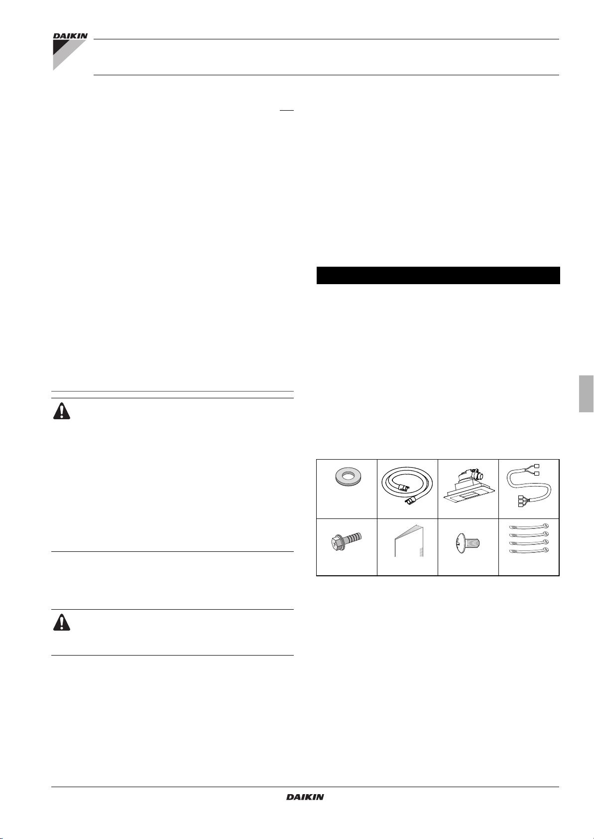
Accessories
Check if the following accessories are included with your unit.
Accessories are kept inside the unit.
Washer for
hanging bracket
4 pieces
Suction hose
Decoration panel
Wire harness
The English text is the original instruction. Other languages are
translations of the original instructions.
Precautions
Installation must be done by a licensed technician.
The choice of materials and installation must comply
with the applicable national and international
regulations.
Do not install or operate the unit in places mentioned below.
- Places with mineral oil, or filled with oil vapour.
- Where volatile flammable gas like thinner or gasoline is used.
- Where the air contains high levels of salt such as air near the
ocean and where voltage fluctuates a lot (e.g. in factories).
- Smoking rooms
- Places where sticky substance are often generated
(e.g. barber shops).
Screws for duct
flanges
Installation and
operation manual
Screws for
bottom flange
4 tie wraps
1
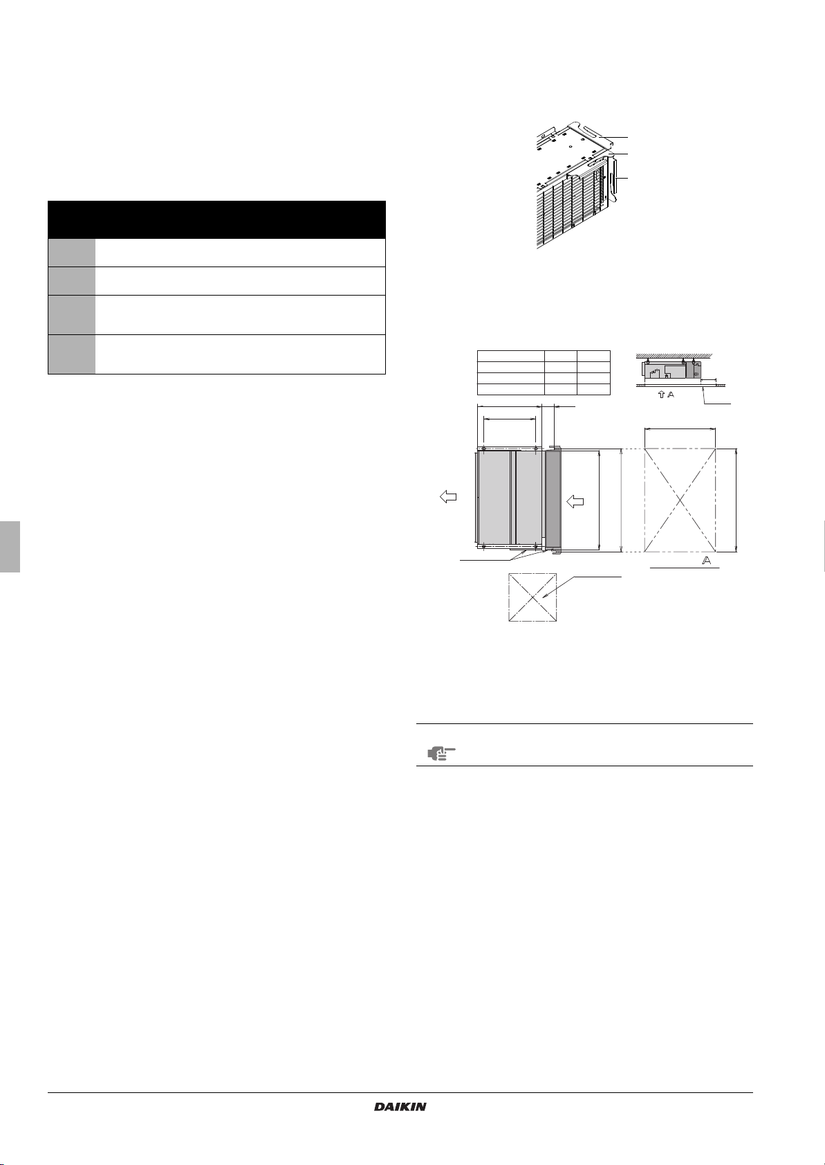
Optional accessories
B
A
620 119
500
450×450
1130
A
830
1030
1230
840
1040
1240
Control box
Air inlet
Suspension
bolt pitch
Air
(Inspection
opening size)
BAE20A62
BAE20A102
BAE20A82
Inspection door
(Ceiling opening)
Arrow view
Ceiling
SERVICE SPACE
(Suspension bolt pitch)
300
Refer to catalogues and technical literature for selecting an
appropriate remote controller.
This option is not intended for bottom suction.
Only use accessories, optional equipment and spare parts made
or approved by Daikin.
For the following items, take special care during construction and check after installation is finished
Tick
when
checked
Is the indoor unit fixed firmly?
The unit may drop, vibrate or make noise.
Is the wiring correct?
The unit may malfunction or components may burn.
Is nothing blocking the air outlet or inlet of either the indoor or
outdoor units?
It may result in insufficient cooling or heating.
Are all accessories, cartons and tapes removed from inside
of the unit?
It may result in unit malfunction.
Notes to the installer
Read this manual carefully to ensure correct installation. Be sure
to instruct the customer how to properly operate the system and
show him/her the enclosed operation manual.
Preparations before installation
Remove all accessories and accessible cartons
(Refer to figure 3 - item 1.) from the inside of the unit.
For installation, choose one of the possibilities listed below.
1
2
3
1 Factory installed hangers
2 Front installation - temporarily remove protection net before
installation.
3 Side installation
1 Factory installed hangers
A
Model
B
Selecting installation site
(See figure 1 and figure 2)
1 Select an installation site where the following conditions are
fulfilled and has meets your customer's approval.
- Where nothing blocks air flow.
- Where sufficient clearance for maintenance and service can
be ensured.
- Where there is no risk of flammable gas leaking.
- The equipment is not intended for use in a potentially
explosive atmosphere.
- When installing the wireless remote controller kit, the
distance between wireless remote controller and indoor unit
might be shorter if there are fluorescent lights, which are
electrically started in the room. The option kit must be
installed as far as possible away from fluorescent lights.
2 Ensure that a protective guard is installed on the air suction side.
The protection must comply with relevant European and national
regulations.
3 Use suspension bolts for installation. Check whether the ceiling
is strong enough to support the weight of the indoor unit and
option kit. If there is a risk, ceiling must be reinforced before
installing the unit.
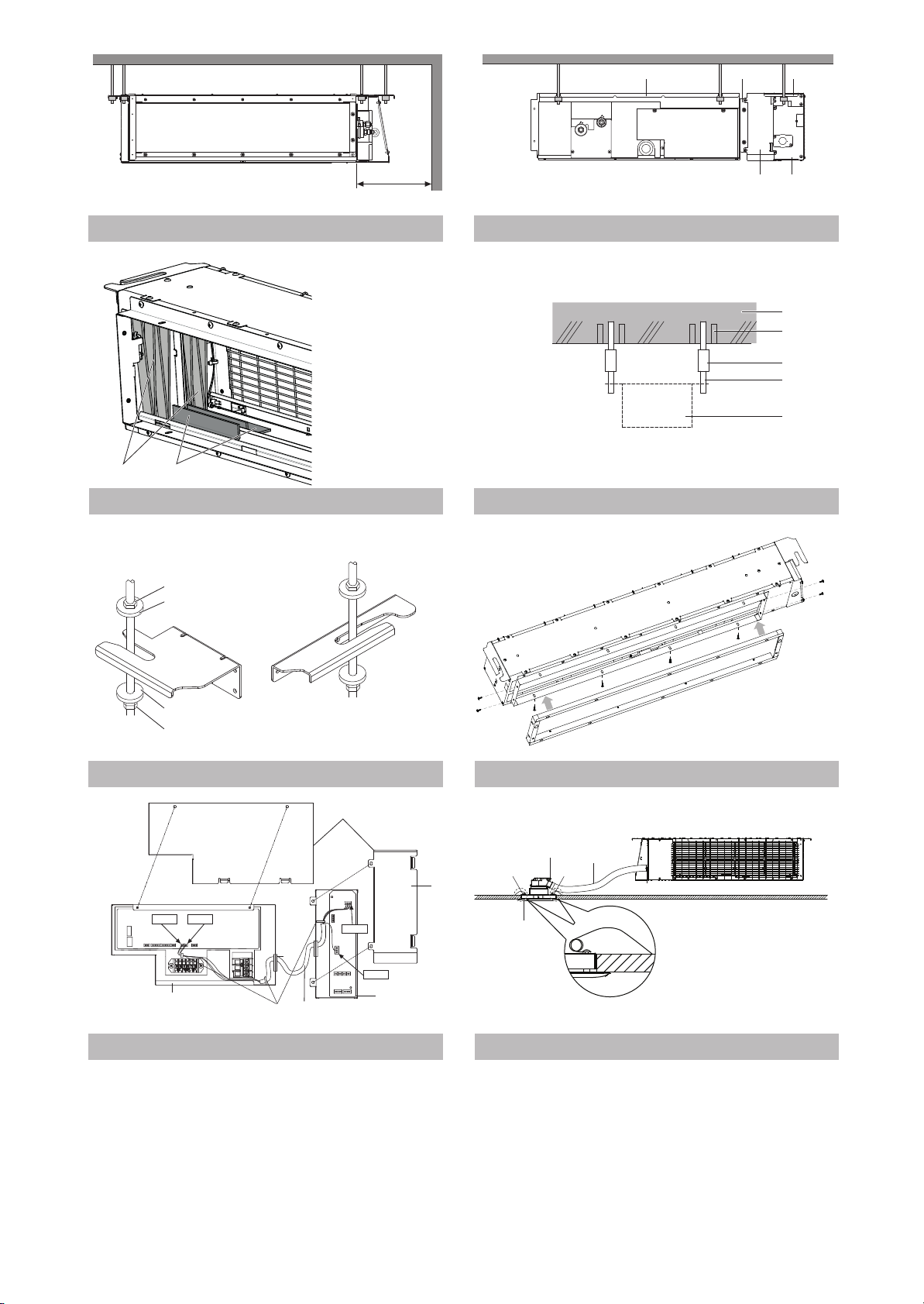
1 Indoor unit
2 Auto-Cleaning option kit
3 Flange connection
4 Hangers
5 Switch box
discharge
(units : mm)
For a different way of installation, the factory set hangers should be
repositioned by an authorized installer.
1 Remove 3 screws.
2 Change hanger position.
3 Put the 3 screws back. (2 screws in case of the side installation)
NOTE
Hanger on switch box side can not be changed.
Relation of the unit to the suspension bolt position.
I
nstall the inspection opening on the control box side where
maintenance and inspection of the control box are easy.
Install the inspection opening also in the lower part of the unit.
Make sure that there is easy access to the filter from a
bottom side.
Install the suspension bolts.
(Use W3/8 to M10 suspension bolts.)
Use a hole-in-anchor, sunken insert, sunken anchor, for
existing ceilings, and a sunken insert, sunken anchor or other
part to be processed in the field to reinforce the ceiling to
bearing the weight of the unit. (Refer to figure 4.)
1 Anchor
2 Ceiling slab
3 Long nut or turn-buckle
4 Suspension bolt
5 Auto-Cleaning option kit
All above parts are field supplied.
2
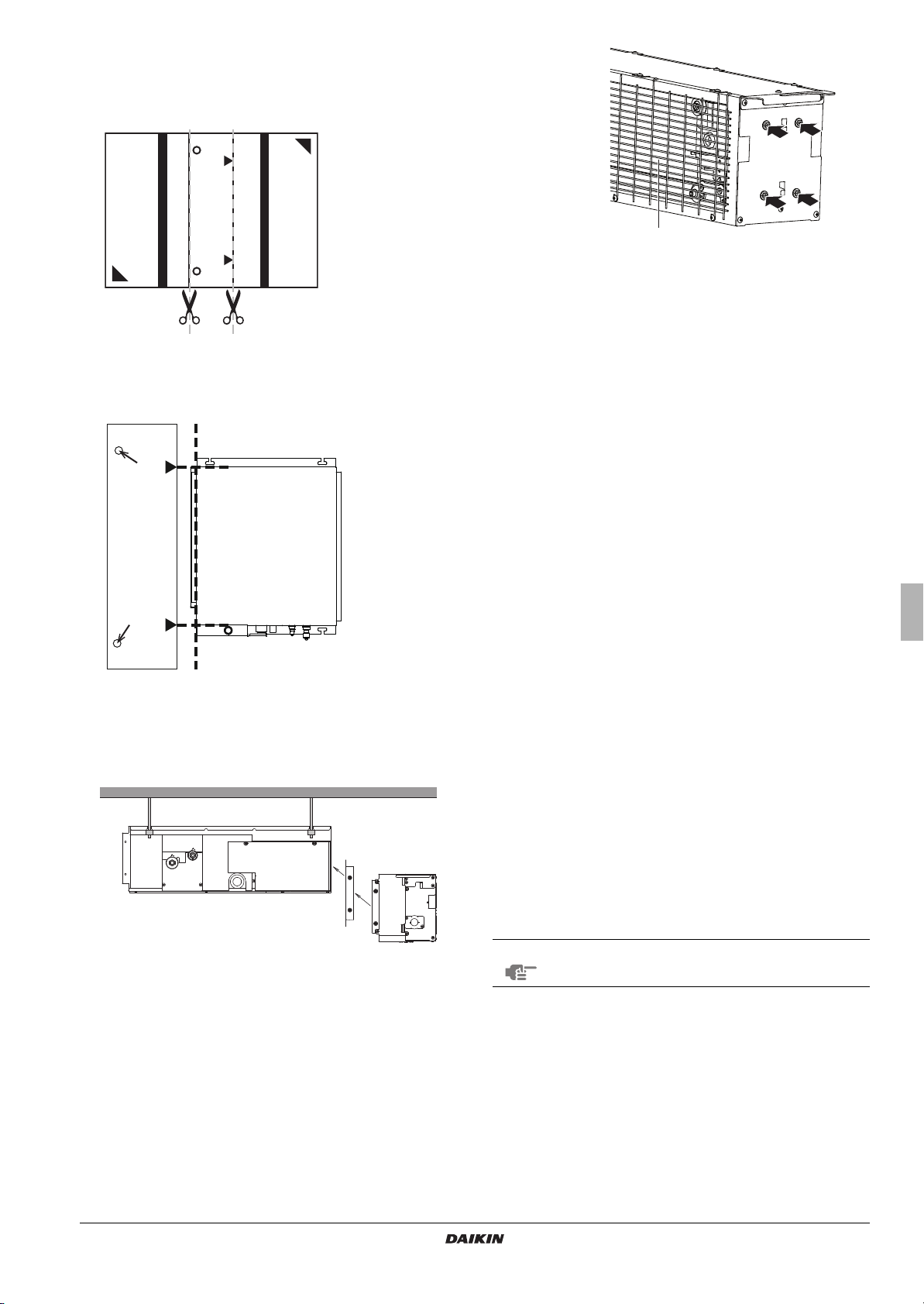
Suspension bolt installation
1
To determine proper bolt position use the carton delivered with the
unit.
1 Cut the carton according to the printed instructions.
2
Place the cut part of the carton next to the already installed duct unit.
Position edge of carton according to the dotted parallel line.
3 Position triangles printed on the carton according to the edge of
casing (dotted lines).
1 Protection net
3 Remove the carton from under both trolleys.
(Refer to figure 3 - item 1.)
4 Install the option kit temporarily.
- Move the option kit to the indoor unit from the bottom side in
order to fix the flanges together.
- Attach the hanger bracket to the suspension bolt. Be sure to
fix it securely by using a nut and washer from the upper and
lower sides of the hanger bracket. (See figure 5)
1 Nut (field supply)
2 Washer for hanger bracket (accessories)
3 Tighten (double nut)
4 Mark position of holes for suspension bolts.
Auto-Cleaning option kit installation
1 Remove a flange from the option and install it to the indoor unit
suction side.
- For the flange use the screws from the accessory bag
(screws with hexagon head).
- Second flange must stay on the option kit.
2 Permanently remove 4 screws holding both trolleys. (Screws are
used only for transportation purpose.)
5 Check if the unit is leveled horizontally.
6 Tighten the upper nut.
7 Screw both flanges together from sides and bottom side. Use
screws with rounded head (accessories). (Refer to figure 6.)
8 Connect the Auto-Cleaning option kit with indoor unit using a
wire harness (accessories) according to figure 7 and according
to chapter "Electric wiring work".
9 Turn ON the indoor unit power supply to let the trolleys perform
initialization and move into parking position (wait until the trolleys
move to switch box side = parking position).
10 Temporarily remove the protection net by loosening all screws
(number of screws differs by casing size) on the lower side.
11 Remove cartons originally covered behind both trolleys -
opposite side from switch box. (Refer to figure 3 - item 2.)
12 Insert the air filter according to chapter "Manual cleaning of filter"
- Remove fixing plate of the filter and insert the air filter into the
unit.
- Fabric strips attached to the filter shall be from bottom side.
- Install the fixing plate back.
13 Reinstall the protection net.
Perform Auto Cleaning test operation according to chapter "Test
operation"
NOTE
Filter cannot be inserted inside the unit unless the
trolleys are in parking position.
Decoration panel installation
See figure 8
1 Decoration panel
2 Connection port on decoration panel
3 Connection port on the Auto-Cleaning option kit
4 Hose
5 Spri ng
1 Attach the hose from the accessory set to the connection port on
the Auto-Cleaning option kit.
Second end of the hose shall be attached to the decoration
panel assembly.
3
 Loading...