

Daihatsu Type A4Q, A4R Automatic Transmission (Electrically-Controlled) Service Manual (NO. 9738)
Page 1
SERVICE MANUAL
This service manual describes the disassembling, checks and assembling procedures
for the unit itself of the FR, four-speed, electronically-controlled automatic transmission.
As for the removal/installation procedures from and to the vehicle and the check procedure for the control system, refer to the Chassis Volume.
Furthermore, in respect to the illustrations, they are for Type A4R-D1, unless there are
problems in describing their operations.
A4Q-D1: J-Type AT
A4R-D1: S-Type AT
TYPE
Automatic Transmission
(Electrically-Controlled)
A4Q, A4R
FOREWORD
Series
Published in May, 2000
NO. 9738
©2000
All rights reserved. This material may not be reproduced or copied, in whole or in part, without the written permission of Daihatsu Motor Co., ltd.
Page 2
SECTION INDEX
TYPE A4Q,A4R
Series
Automatic Transmission
(Elecrically-Controlled)
SECTION NAME
GENERAL INFORMATION
AUTOMATIC TRANSMISSION
SECTION
GI
AT
NO. 9170-AE
Page 3

GENERAL INFORMATION
TO INDEX
IMPORTANT SAFETY NOTICE ...................... GI–2
WARNINGS, CAUTIONS AND NOTES ...... GI–2
HOW TO USE THIS MANUAL ........................ GI–4
CONTENTS OF EXPLANATION ................ GI–4
ABBREVIATION CODES ............................... GI–6
GENERAL SERVICE INSTRUCTION ............ GI–7
JGI00001-00000
GI
Page 4

GI–2
IMPORTANT SAFETY NOTICE
The vehicle is a machine comprising a great number of parts. Basically speaking, the vehicle is potentially hazard. However, one can handle it safely if he has the required knowledge.
Correct service methods and repair procedures are very vital for assuring not only the safety and reliability of a vehicle, but also the safety of service personnel concerned.
The methods and procedures contained in this manual describe in a general way the techniques
which the manufacturer has recommended. Thus, they will contribute to ensuring the reliability of
the products. The contents of the servicing operations come in a wide variety of ways. Moreover,
techniques, tools and parts necessary for each operation are different widely from each other.
This manual does not cover all details of techniques, procedures, parts, tools and handling instructions which are necessary for these operations, for such coverage is impossible. Hence, any one
who obtains this manual is expected first to make his responsible selection as to techniques, tools
and parts which are necessary for servicing the vehicle concerned properly. Furthermore, he must
assume responsibility for his actions in connection with his own safety.
Therefore, one should not perform any service if he is not capable of making responsible selection
and/or if he can not understand the contents herein described, for this manual has been prepared
for experienced service personnel.
WARNINGS, CAUTIONS AND NOTES
All these symbols have their specific purposes, respectively.
WARNING:
• This symbol means that there is the possibility of personal injury of the operator himself or the
nearby workers if the operator fails to follow the operating procedure prescribed in this manual.
CAUTION:
• This symbol means that there is the possibility of damage to the component being repaired if
the operator fails to follow the operating procedure prescribed in this manual.
NOTE:
• To accomplish the operation in an efficient manner, additional instructions concerning the operation are given in this section.
The following list describes general WARNINGS:
• Always wear safety glasses for eye protection.
• Use safety stands whenever a procedure requires you to be under the vehicle.
• Be sure that the ignition switch is always in the OFF position, unless otherwise required by
the procedure.
• Set the parking brake when working on the vehicle.
• Operate the engine only in a well-ventilated area to avoid the danger of carbon monoxide.
• Keep yourself and your clothing away from moving parts, when the engine is running, espe-
cially from the fan and belts.
• To prevent serious burns, avoid contact with hot metal parts such as the radiator, exhaust
manifold, tail pipe, catalytic converter and muffler.
• Do not smoke while working on a vehicle.
• To avoid injury, always remove rings, watches, loose hanging jewelry, and loose clothing be-
fore beginning to work on a vehicle.
• Keep hands and other objects clear of the radiator fan blades! The electric cooling fan is
mounted on the radiator and can start to operate at anytime by a rise in coolant temperature
Page 5
or turning ON of the air conditioner switch in the case of vehicles equipped with an air conditioner. The electric cooling fan is also mounted on the condenser for air conditioner and starts
to operate anytime when the air conditioner switch is turned “ON”. For this reason care should
be taken to ensure that the electric cooling fan motor is completely disconnected when working under the hood.
The UNITS used in this manual are showed as the SI UNIT (International System of Unit).
“Example”
24.5 - 34.3 N·m
GI–3
JGI00002-00000
Page 6
GI–4
FRONT
B
B
6.9 - 9.8
14.7 - 17.6
!2
!1
!0
o
★
i
y
r
u
t
q
w
e
HOW TO USE THIS MANUAL
CONTENTS OF EXPLANATION
1. Schematic Diagram of Components
(1) The schematic diagram of components that appears at the beginning of each section describes the
nomenclature and installed conditions of each component. Furthermore the tightening torque is
posted in the figure.
(2) Those parts whose reuse is not permitted bear a “
to replace these parts with new ones during the assembly.
(3) During the assembly, be sure to apply grease to those parts indicated by the mark in the figure.
(Example)
★” mark for an identification purpose. Be certain
: Tightening torque
★ : Non-reusable parts
Unit : N⋅m
q Torsion spring
w Parking lock pawl shaft
e Parking lock pawl
r Manual valve lever
t Manual valve idler shaft
y Manual valve idler plug
u Parking lock rod
i Parking lock lever
o Manual lever shaft
!0 Slotted spring pin
!1 Paring lock cam support
!2 Manual detent spring
JGI00003-00001
Page 7
GI–5
SST
2. Servicing Procedure
(1) In principle, the servicing procedure is described in the following sequence given below: Removal
→ Inspection → Installation, and Disassembly → Inspection → Assembly.
(2) The explanation covers detailed servicing methods, specifications and notes.
(3) The main point of each item explains the servicing section and servicing procedure, using illustra-
tions.
(Example)
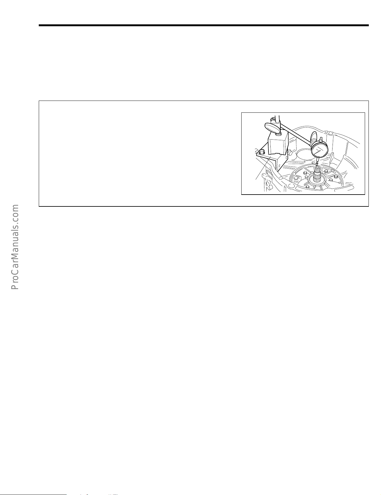
15. Remove the stator shaft & oil pump assembly.
(1) Measure the input shaft end play, using a dial
gauge and following SST.
SST: 09350-87202-000 (09351-87210-000)
Specified Value: 0.26 - 0.88 mm
NOTE:
• Be sure to record the measured value for a guide
during the assembly.
(4) The inspection in this manual describes only checking
operation. Therefore, if you find any malfunction, replace any defective parts with new ones.
3. SST
For those operations which require the use of any SST, the SST numbers concerned are given in bold
letters.
4. Service Specifications
Service specifications are indicated in bold letters or enclosed by heavy lines. Be certain to confirm the
specifications concerned.
5. Tightening Torque
For those operations which require the control of tightening torque, the relevant tightening torque is
given in bold letters. Be certain to confirm the tightening torque concerned.
6. Definitions of Terms
Specified Value.......... A value which represents the allowable range during the inspection and adjust-
Limit ........................... A maximum or a minimum limit which the value should not exceed or fall below.
JGI00004-00002
ment.
JGI00005-00000
Page 8
Bolt
Nut
Screw
Washer
B
N
S
W
GI–6
SAE
SST
Society of Automotive
Engineers
Special Service Tool
For example, automotive oils are designated as SAE so and so number.
These designation numbers have been set forth by the Society of Automotive
Engineers in the United States of America (SAE). The larger the SAE number, the
higher the oil viscosity. Conversely, the smaller the SAE number, the lower the oil
viscosity.
Refers to a tool designed for a specific purpose.
When referring to automotive parts, “standard” represents those parts which have been
installed originally by the manufacturer and which have standard dimensions.
STD Standard
T
Torque
Refers to tightening torque.
VSV
Vacuum Switching
Valve
Refers to vacuum switching valve.
W/
With
Denotes that the following part is attached.
Abbreviation code
API
Assy, A/Y or Ay
A/T, AT
EFI
EJ-BE
ISC
IGN
LH
LHD, L.H.D.
MP
RH
RHD, R.H.D.
S/A
Original word
American Petroleum
Institute
Assembly
Automatic Transmission
Electronic Fuel Injection
EJ-D EFI
Idle Speed Control
Ignition
Left Hand
Left-Hand Drive
Multipurpose
Right Hand
Right-Hand Drive
Sub-Assembly
Meaning
The standards set forth by the American Petroleum Institute (abbreviated as API
Classification) have been employed to evaluate and classify properties of various oils.
Engine oils for gasoline engines are classified as SD, SE, SF and so on, whereas
engine oils for diesel engines are classified as CC, CD and so on.
Refers to an assembled component comprising more than two single parts or subassembly parts.
Refers to automatic transmission
Refers to electronic fuel injection.
EJ engine equipped with EFI system
Refers to idle speed control
Refers to ignition
Refers to left side.
Left-hand drive vehicle.
Means that the following item has multi-purposes.
Refers to right side.
Right hand drive vehicle
Refers to a component comprising more than two single parts which are welded,
staked, or studded to each other to form a single component.
ABBREVIATION CODES
The abbreviation codes that appear in this service manual stand for the following, respectively.
The abbreviation codes that appear in the figure stand for the following, respectively.
JGI00006-00000
JGI00007-00000
Page 9

GI–7
TO INDEX TO NEXT SECTION
GENERAL SERVICE INSTRUCTION
1. Use fender covers, seat covers and floor sheets so that the vehicle may not get dirty or be scratched.
2. Jacking up
(1) When only the front section or rear section of the vehicle is jacked up, be sure to place chocks at
the wheels so as to insure safe operations.
(2) When the vehicle has been jacked up, be sure to support the vehicle at the specified section using
the safety stands. (Refer to the relevant Chassis section in the manual for the vehicle concerned.)
3. Handling instructions related to battery.
(1) Before you start performing the electrical works, make certain to disconnect the battery ground
cable terminal from the negative (–) terminal of the battery.
NOTE:
• Before disconnecting the battery ground cable terminal from the negative (–) terminal of the battery,
be sure to read out the diagnosis code of the EFI systems if it equipped.
• After reconnect the battery ground cable terminal to the negative terminal of the battery, be sure to
reset the watch or radio, if vehicle equipped with such equipments.
(2) When it becomes necessary to disconnect the battery power supply for the purpose of carrying out
checks or repairs, always disconnect the negative (–) terminal of the battery ground cable from negative terminal of the battery first.
(3) To avoid damaging battery plates, after the terminal nut has been loosened, pull out the battery
ground cable terminal straight upward, rather than turning or prying the terminal.
NOTE:
• Be sure to employ the battery terminal puller (commercially available) to remove battery ground cable
terminal from the negative terminal of the battery, if encountered any difficulty.
(4) Clean the battery terminal posts or battery ground terminals, using a cloth. Never use a file or other
adhesive agents.
(5) When connecting the battery ground cable terminal to the battery, first the battery ground cable ter-
4. For increased work efficiency and improved accuracy, be sure to utilize the SSTs (Special Service Tools)
minal should be fitted onto the battery post with the attaching nut in a loose state.
Then, tighten the nut. Never tap the terminal onto the battery post, using the hammer or spanner
wrench or the like.
(6) As for the cover at the positive (+) terminal side, be sure to install it at the correct position.
effectively.
JGI00008-00000
Page 10

TO INDEX
AT
AUTOMATIC TRANSMISSION
OUTLINE ......................................................AT–2
SECTIONAL VIEW OF AUTOMATIC
TRANSMISSION .................................AT–2
COMPONENTS ............................................AT–3
COMPONENTS (INNER PARTS) .............AT–5
REMOVAL ....................................................AT–7
INSPECTION ...............................................AT–17
FRONT AND REAR MULTIPLE
CLUTCH ASSEMBLY ..........................AT–17
ONE-WAY CLUTCH ................................AT–18
ASSEMBLY ..................................................AT–19
SST (Special Service Tools) ......................AT–36
TIGHTENING TORQUE ...............................AT–39
JAT00001-00000
Page 11
AT–2
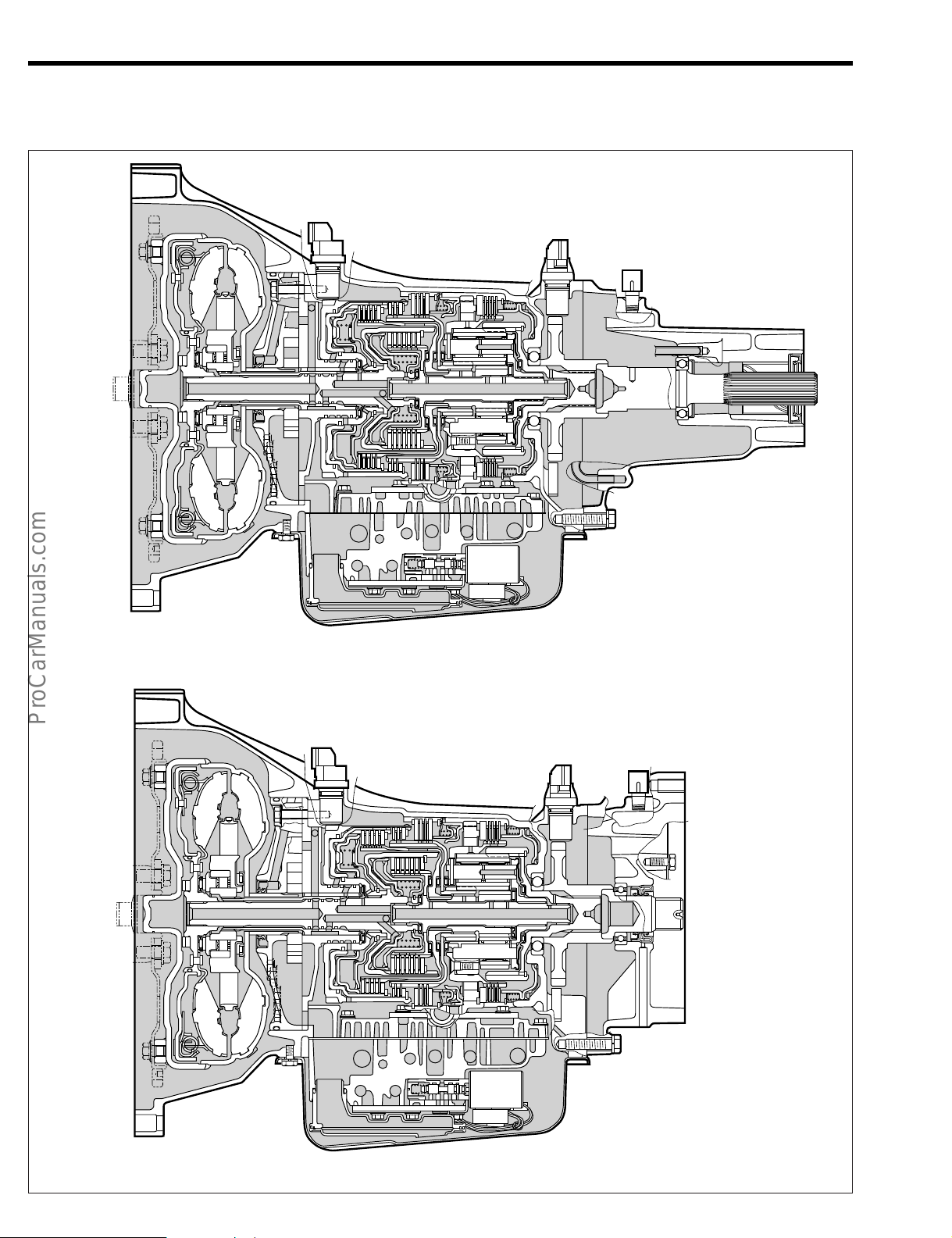
<2WD>
<4WD>
OUTLINE
SECTIONAL VIEW OF AUTOMATIC TRANSMISSION [A4Q-D1]
JAT00002-00001
Page 12

COMPONENTS
FRONT
B
B
B
B
B
B
B
B
B
B
N
B
B
B
B
14.7 - 21.6
19.6 - 29.4
6.9 - 9.8
6.9 - 9.8
6.9 - 9.8
6.9 - 9.8
6.9 - 9.8
2.9 - 9.8
6.9 - 9.8
6.9 - 9.8
14.7 - 21.6
9.8 -15.7
14.7 - 21.6
14.7 - 21.6
14.7 - 21.6
29.4 - 44.1
2WD
@6
@7
@9
@8
@5
#0
@4
@3
@2
★
★
★
@1
@0
★
!7
!5
!5
!4
!3
!2
i
★
!6
★
★
★
★
★
★
★
!6
!8
!9
!1
!0
#1
e
r
t
w
q
o
y
u
AT–3
: Tightening torque
★ : Non-reusable parts
Unit : N·m
q Transmission control shaft lever sub-
assembly
w Neutral start switch
e T-type oil seal
r Breather plug cap
t Breather plug union
y Control cable bracket
[A4Q-D1, A4R-D1 (4WD)]
u Neutral start switch bracket
i Transmission oil filler tube
o Oil guide plate
!0 Transmission solenoid connector
subassembly
!1 Transmission case side cover
!2 O-ring
!3 T-type oil seal
!4 Knock pin
!5 Transmission revolution sensor
!6 O-ring
!7 2nd & 4th brake cylinder tube
!8 Compression spring
!9 Plate
@0 O-ring
@1 Oil strainer
@2 Magnet
@3 Oil pan
@4 Gasket
@5 Drain plug
@6 Extension housing
@7 T-type oil seal
@8 Knock pin
@9 Oil pipe
#0 Engine mount bracket
[A4R-D1 (2WD)]
JAT00003-00002
Page 13

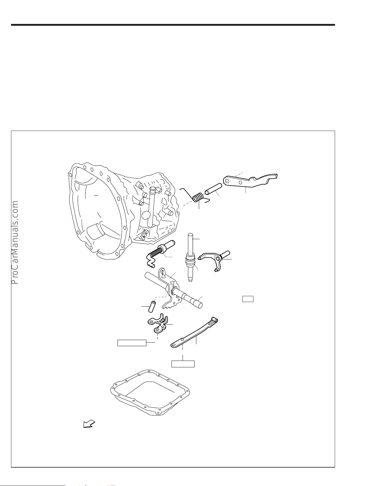
AT–4
FRONT
B
B
6.9 - 9.8
14.7 - 17.6
!2
!1
!0
o
★
i
y
r
u
t
q
w
e
q Torsion spring
w Parking lock pawl shaft
e Parking lock pawl
r Manual valve lever
t Manual valve idler shaft
y Manual valve idler plug
u Parking lock rod
i Parking lock lever
o Manual lever shaft
!0 Slotted spring pin
!1 Paring lock cam support
!2 Manual detent spring
JAT00128-00124
Page 14

COMPONENTS (INNER PARTS)
2WD
#0
@9
@9
#0
q
w★
w★
w★
A
e
B
C
C
C
r
t
y
u
i
o
!1
!0
!0
!0
!1
!1
!2
!3
!4
!5
!6
!7
★
!8
!9
@0
@0
@0
@0
@1
@1
@1
@1
★
@2
D
@3
@4
@5
@6
@7
@8
Outer diameter
Inner diameter
Thickness
44.5
29.7
44.5
29.7
A B C D
3.81
3.41
4.21
30
14
3.62
57
41.4
3.91 3.81
Thrust bearing specification
AT–5
★ : Non-reusable parts
★★ : Selection parts
q Front multiple clutch assembly
w Oil seal ring
e Rear multiple clutch assembly
r Intermediate shaft
t Forward clutch hub
y Planetary sun gear
u Rear planetary sun gear
i Hole snap ring
o Flange
!0 Brake disc
!1 Brake plate
!2 Hole snap ring
!3 Retainer
!4 Wave spring
!5 2nd & 4th brake piston
!6 2nd & 4th brake cylinder
!7 One-way clutch
!8 Hole snap ring
!9 Brake flange
@0 Brake disc
@1 Brake plate
@2 Planetary gear ay.
@3 Planetary output shaft
@4 Hole snap ring
@5 Retainer
@6 Wave spring
@7 1st & reverse brake piston
@8 Radial ball bearing
@9 Reduction drive gear
#0 Radial ball bearing
JAT00004-00003
Page 15
AT–6
FRONT
B
B
B
B
B
B
B
B
q
!4
!5
w
u★
i★
o★
!0★
6.9 - 9.8
4.9 - 6.9
e
r
!1
!2
!3
y
t
4.9 - 6.9
4.9 - 6.9
4.9 - 6.9
4.9 - 6.9
4.9 - 6.9
4.9 - 6.9
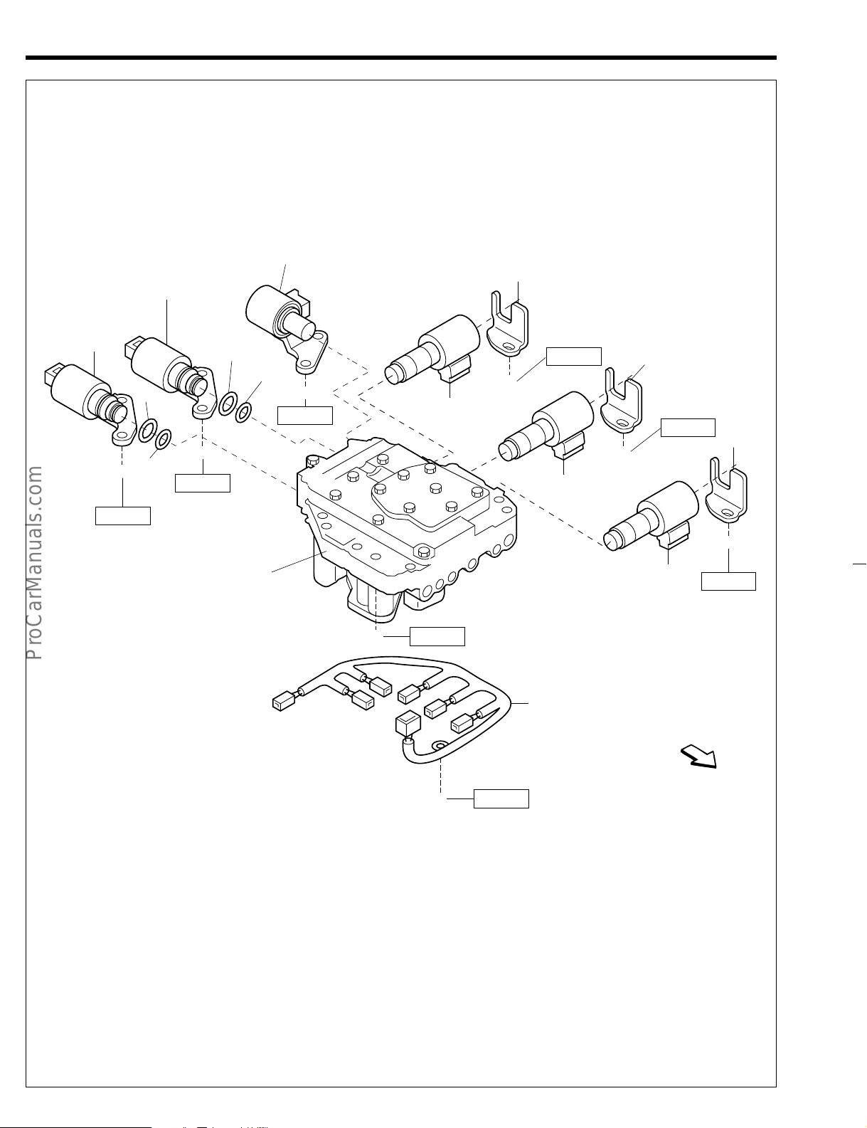
q Lockup clutch control solenoid Ay
w Transmission 3-way solenoid Ay
e Transmission 3-way solenoid Ay
r Clutch control solenoid Ay No. 1
t Clutch control solenoid Ay No. 2
y Clutch control solenoid Ay No. 3
u O-ring
i O-ring
o O-ring
!0 O-ring
!1 Bracket
!2 Bracket
!3 Bracket
!4 Valve body assembly
!5 Wire harness
JAT00129-00125
Page 16
REMOVAL
O-ring
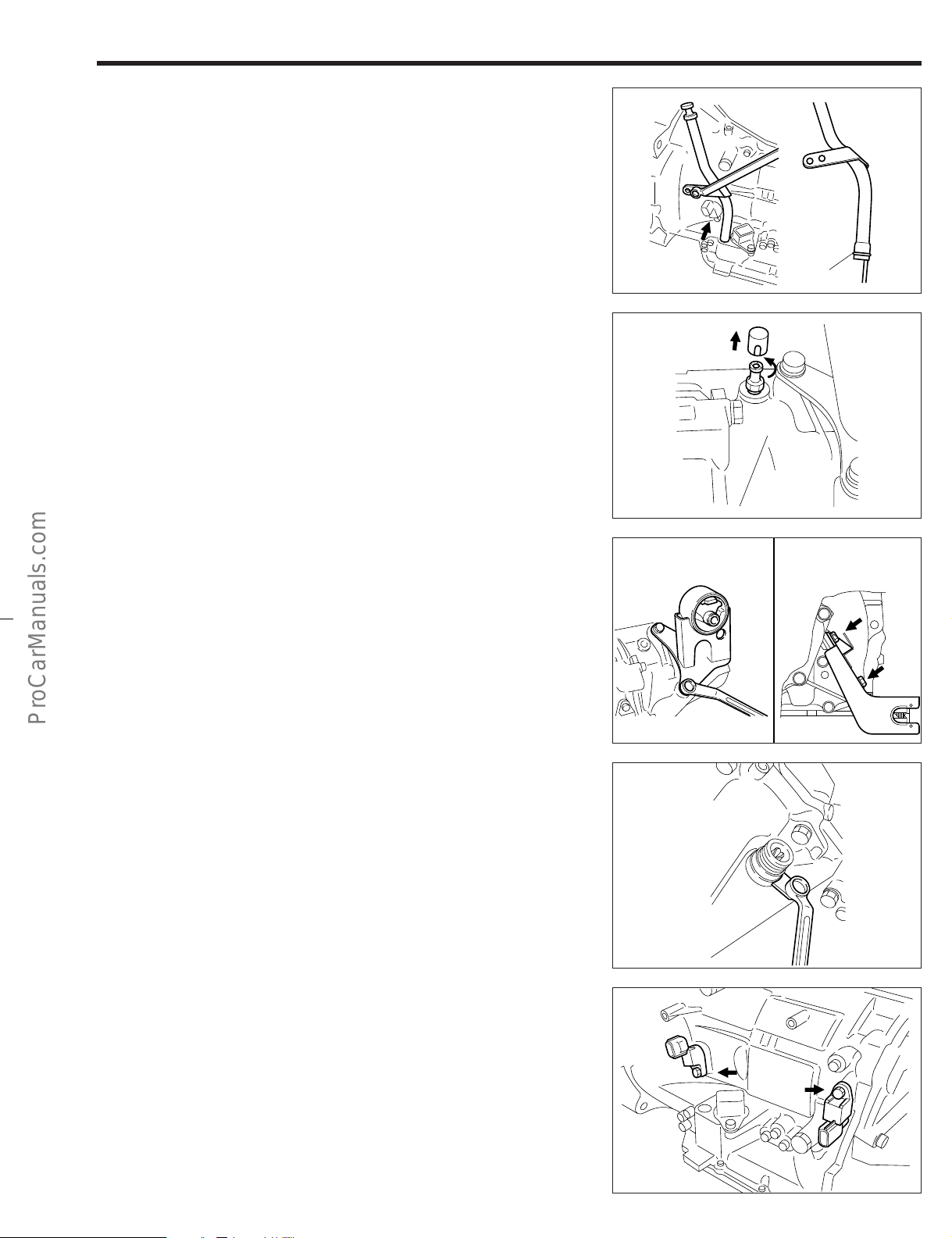
1. Remove the bolt of the transmission oil filler tube subassembly.
2. Pull out the tube subassembly upwards.
3. Remove the O-ring from the tube subassembly.
NOTE:
• Never reuse the removed O-ring.
4. Removal of breather plug.
(1) Remove the breather plug cover and the breather plug
union.
NOTE:
• Never reuse the removed unions, and cover.
• Number of breather plugs.
2WD: 1
4WD: 2
AT–7
JAT00005-00004
5. Removal of bracket.
(1) Remove the 3 bolts of the engine mount bracket.
[A4R-D1 (2WD)]
Remove the 2 bolts of the control cable bracket.
[A4Q-D1, A4R-D1 (4WD)]
6. Removal of speedometer shaft sleeve subassembly.
[A4R-D1]
(1) Remove the speedometer sleeve lock plate by remov-
ing a bolt.
(2) Remove the speedometer shaft sleeve subassembly,
using the flat screwdriver.
NOTE:
• Never reuse the removed O-ring of the speedometer
shaft sleeve subassembly.
7. Remove the two transmission revolution sensors by removing the bolts.
NOTE:
• Never reuse the removed O-rings of the transmission
revolution sensors.
Engine mount bracket
A4R-D1 (2WD)
A4R-D1
JAT00006-00005
Coutrol cable bracket
A4Q-D1, A4R-D1 (4WD)
JAT00007-00006
JAT00008-00007
JAT00009-00008
Page 17
AT–8
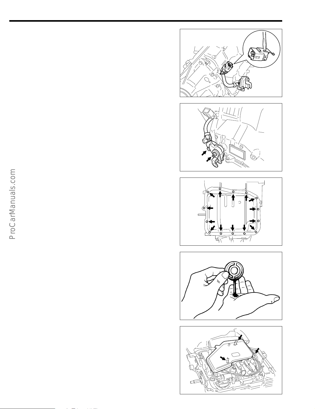
8. Removal of neutral start switch assembly
(1) Disassemble the coupler from the bracket using a flat
screwdriver.
NOTE:
• In the case of A4Q-D1, the direction of the coupler dif-
fers from that of A4R-D1.
(2) Remove the neutral start switch assembly by removing
the bolt and nut.
9. Remove the valve body assembly.
(1) Remove the 14 bolts of the transmission oil pan sub-
assembly.
(2) Remove the transmission oil pan subassembly by gen-
tly tapping on the rim, with a plastic hammer.
CAUTION:
• Do not turn over the transmission, for this will contami-
nate the valve body with foreign materials deposited at
the bottom of the oil pan.
JAT00010-00009
JAT00011-00010
NOTE:
• Never reuse the removed transmission oil pan sub-
assembly.
(3) Check of pan for particles.
Remove the magnet and use it to collect any steel
chips. Inspect the oil pan for any chips and particles
collected on the magnet to find out the type of wear of
the transmission.
Steel (magnetic) ... Wear of bearing, gear and plate
Brass (nonmagnetic) ... Wear of bush
(4) Turn over the transmission.
NOTE:
• This turning-over of the transmission is necessary, for
the control-related parts would drop when the valve
body is removed if the transmission was not turned
over.
(5) Remove the oil strainer subassembly by pushing out
the 3 pawls of the oil strainer using a flat screwdriver.
CAUTION:
• The strainer subassembly has 3 pawls. Be very careful
not to break or bend them during removal.
JAT00012-00011
JAT00013-00012
NOTE:
• Be sure to check whether the mesh of oil strainer is
clean.
JAT00014-00013
Page 18
(6) Remove the O-ring from the stem of the oil strainer.
NOTE:
• Never reuse the removed O-ring.
(7) Remove the manual detent spring by removing the 2
bolts.
NOTE:
• Be sure to remove the bolts evenly and uniformity.
AT–9
JAT00015-00014
(8) Detach the harness from the clamp of the valve body
assembly.
(9) Disconnect the connector, using a flat screwdriver.
NOTE:
• Never pull out the wire itself directly when you disconnect the connector.
10. Remove the valve body and the bracket by removing the 7
bolts.
NOTE:
• Be sure to remove the bolts evenly and diagonally.
• The numerals in the right illustration indicate the nomi-
nal length of the bolt.
#5
#5
^5
JAT00016-00015
JAT00017-00016
JAT00018-00017
#5
#5
#5
#5
JAT00019-00018
Page 19

AT–10
Manual valve
lever pin
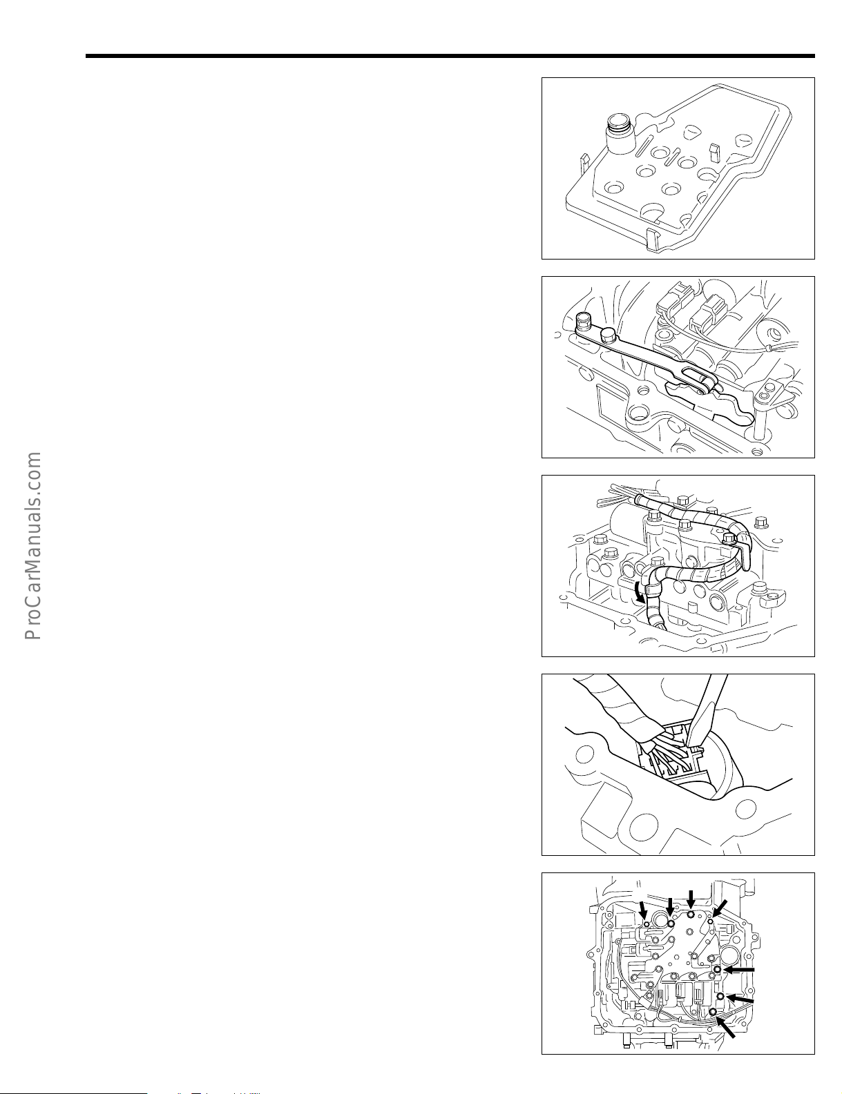
11. Remove the manual valve sleeve by pulling up the manual
valve lever pin.
12. Remove the compression spring by removing the bolt and
plate.
13. Remove the 2nd & 4th brake cylinder seal.
NOTE:
• Never reuse the removed seal.
JAT00020-00019
2nd & 4th brake
cylinder seal
14. Remove the manual lever subassembly.
(1) Remove the slotted spring pin, using a pin punch and
a hammer.
NOTE:
• When removing the pin, be very careful not to drop it
into the transmission case.
• Never reuse the removed pin.
(2) Pull out the manual valve lever shaft toward the out-
side.
(3) Remove the manual lever subassembly and parking
lock rod subassembly.
15. Remove the stator shaft & oil pump assembly.
(1) Measure the input shaft end play, using a dial gauge
and following SST.
SST: 09350-87202-000 (09351-87210-000)
Specified Value: 0.26 - 0.88 mm
JAT00021-00020
JAT00022-00021
Manual lever
Parking lock rod
JAT00023-00022
NOTE:
• Be sure to record the measured value for a guide dur-
ing the assembly.
SST
JAT00024-00023
Page 20
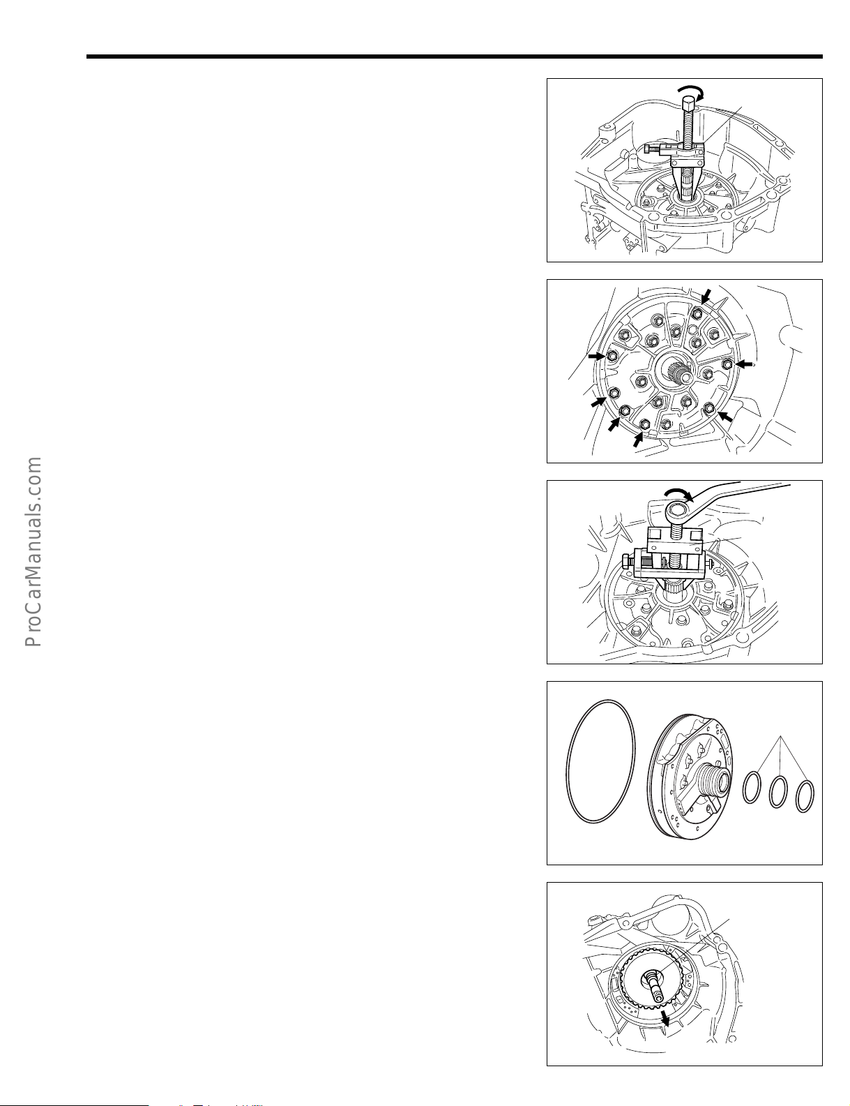
(2) Remove the T-type oil seal, using the following SST.
SST
SST: 09308-10010-000
NOTE:
• Never reuse the removed oil seal.
(3) Remove the 7 bolts of the stator shaft & oil pump as-
sembly.
NOTE:
• Be sure to remove the bolts evenly and diagonally.
• Never loosen any bolt other than the specified ones in
the right figure.
AT–11
JAT00025-00024
(4) Remove the stator shaft & oil pump assembly with the
O-ring, using the following SST.
SST: 09820-00021-000
(5) Remove the O-ring from the stator shaft & oil pump as-
sembly and the 3 clutch drum oil seal rings.
NOTE:
• Never reuse the removed O-ring.
• Never reuse the removed oil seal rings.
16. Remove the front and rear multiple clutch assembly.
(1) Pull out the front and rear multiple clutch assembly by
holding the stator shaft.
NOTE:
• Do not touch the seal rings.
JAT00026-00025
SST
JAT00027-00026
Seal rings
JAT00028-00027
Seal rings
JAT00029-00028
Page 21
AT–12
Bearing
Front multiple
clutch assembly
Rear multiple
clutch assembly
(2) Separate the front multiple clutch assembly with the
rear multiple clutch assembly.
(3) Remove the thrust needle bearing from the front multi-
ple clutch assembly.
(4) Remove the 3 oil seal rings from the rear multiple
clutch assembly.
NOTE:
• Never reuse the removed seal rings.
17. Removal of intermediate shaft subassembly.
(1) Remove the intermediate shaft subassembly.
(2) Remove the thrust needle bearing from the intermedi-
ate shaft subassembly.
JAT00030-00029
Bearing
18. Removal of forward clutch hub.
(1) Remove the forward clutch hub.
(2) Remove the thrust needle bearing from the forward
clutch hub.
19. Removal of planetary sun gear assembly.
(1) Remove the planetary sun gear assembly.
(2) Remove the two thrust needle bearings from the plane-
tary sun gear assembly.
20. Removal of the rear planetary sun gear subassembly.
(1) Remove the rear planetary sun gear subassembly.
Intermediate shaft subassembly
JAT00031-00030
Bearing
JAT00032-00031
Bearings
Planetary sun
gear assembly
JAT00033-00032
Rear planetary sun gear
JAT00034-00033
Page 22

21. Measurement of 2nd & 4th and 1st & reverse brake end
1st & Rev.
2nd & 4th
Thickness
gauge
play.
(1) Turn over the transmission case.
(2) Measure the 2nd & 4th brake end play from window
(A), using a thickness gauge.
Specified Value: 1.08 - 1.53 mm
(3) Measure the 1st & reverse brake end play from win-
dow (B), using a thickness gauge.
Specified Value: 0.69 - 1.18 mm
NOTE:
• As for the 1st & reverse brake end play, the measurement should be conducted between the snap ring and
the flange.
• Be sure to record the measured value for a guide during the assembly.
• The tightness which you encounter during this insertion/withdrawal of the thickness gauge should be virtually the same as the tightness which you would encounter during the thickness adjustment of the valve
rocker arm.
AT–13
JAT00035-00034
22. Removal of 2nd & 4th brake discs and plates.
(1) Remove the hole snap ring, using snap ring pliers.
(2) Move the brake flanges, brake discs and brake plates
in a set faces toward the front side and remove them in
the following order.
F = Brake flange, D = Brake disc, P = Brake plate
F → D → P → D → P → D → F
23. Removal of 2nd & 4th brake piston assembly.
(1) Remove the hole snap ring, using snap ring pliers.
(2) Remove the piston return spring seat, piston return
spring, and the 2nd and 4th piston.
(3) Divide the 2nd and 4th brake piston using pliers.
NOTE:
• Never reuse the divided piston.
2nd & 4th
piston
Piston return
spring seat
JAT00036-00035
Piston return spring
Hole snap
ring
JAT00037-00036
JAT00038-00037
Page 23

AT–14
Planetary gear Ay
One-way clutch
#5
#5
#5
#5
#5
170
#5
(A)
A4Q-D1
#5
4WD
170
24. Removal of the one-way clutch and the planetary gear assembly.
(1) Remove the planetary gear assembly with the one-way
clutch installed.
(2) Remove the one-way clutch from the planetary gear
assembly.
25. Removal of the 1st and reverse brake discs and plates.
(1) Remove the thrust needle roller bearing from the plan-
etary output shaft subassembly.
JAT00039-00038
Bearing
(2) Remove the hole snap ring, using snap ring pliers, and
move the brake flange, brake discs and brake plates
in a set faces toward the front side and remove them in
the following order.
F = Brake flange, D = Brake disc, P = Brake plate
F → D → P → D → P → D → P → D → P
26. Removal of the transfer assembly [4WD]
(1) Remove the 7 bolts of the transfer assembly.
NOTE:
• Be sure to loosen the bolts evenly and diagonally
• For A4Q-D1, remove the bolt marked (A), too. (Total 8
bolts)
• The numeral in the right figure indicates the nominal
length of the bolt.
(2) Remove the transfer assembly.
(3) Remove the oil guide plate, by removing the 2 bolts.
(B)
JAT00040-00039
Cut-out section
JAT00041-00040
JAT00130-00126
Removal of the extension housing [2WD], side cover
[4WD].
(1) Remove the oil seal, using the following SST given
below.
SST: 09950-20017-000
SST
JAT00042-00041
Page 24

(2) Remove the 8 bolts of the extension subassembly.
(A)
(A)
2WD
[2WD]
Remove the 10 bolts of the side cover. [4WD]
NOTE:
• Be sure to loosen the bolts evenly and diagonally.
• For A4Q-D1, remove the bolts marked (A), too. (Total
10 bolts)
AT–15
JAT00043-00042
4WD
(3) Remove the extension housing or side cover sub-
assembly by lightly and uniformly tapping the 2 rib
sections, using a plastic hammer.
27. Removal of the output shaft.
(1) Remove the output shaft.
(2) Remove the bearing by using SST.
SST: 09950-20017-000
NOTE:
• Never reuse the removed bearing.
(3) Remove the speedometer drive gear. [A4R-D1]
28. Remove the parking lock pawl.
(1) Remove the torsion spring, the parking lock pawl and
the parking lock pawl shaft.
JAT00000-00127
JAT00044-00043
A4R-D1
SST
Speedometer
drive gear
Bearing
JAT00052-00051
Parking lock pawl
Shaft
Torsion spring
JAT00046-00045
Page 25

AT–16
29. Removal of the planetary output shaft.
(1) Tap the planetary output shaft subassembly lightly,
using a plastic hammer, until it becomes free.
NOTE:
• Be sure to place a cloth or the like under the transmis-
sion case in case that the planetary output shaft subassembly drops.
(2) Remove the bearing.
NOTE:
• If any difficulty is encountered in removing the bearing,
remove it by applying a light impact from the inside of
the transmission case, using a brass bar and a plastic
hammer.
JAT00047-00046
30. Removal of control-related parts:
(1) Remove the parking lock pawl can support by remov-
ing 3 bolts.
(2) Remove the manual valve idler shaft.
31. Remove the 1st & reserve brake assembly.
(1) Remove the shaft snap ring q, using snap ring pliers.
(2) Remove the piston return spring seat w and, piston re-
turn spring e.
(3) Applying compressed air of 392 - 784 kPa from the oil
hole indicated in the right figure.
(4) Remove the 1st & reverse piston r.
WARNING:
• Care must be exercised as to oil splashing when com-
pressed air is used for blowing.
JAT00048-00047
Parking lock pawl cam support
Manual valve idle shaft
JAT00049-00048
q
w
e
r
JAT00050-00049
Apply air
NOTE:
• Never reuse the removed 1st & reverse piston.
JAT00051-00050
Page 26
INSPECTION
FORWARD CLUTCH
FRONT AND REAR MULTIPLE CLUTCH
ASSEMBLY
1. Check of forward clutch (C2) piston stroke and Rear
clutch (C3) piston stroke
(1) Measure the forward clutch (C2) end play, Rear clutch
end play using a thickness gauge.
Specified Value:
Forward Clutch (C2): 0.67 - 0.98 mm
Rear Clutch (C3): 1.24 - 1.55 mm
NOTE:
• The tightness which you encounter during this inser-
tion/withdrawal of the thickness gauge should be virtually the same as the tightness which you would encounter during the thickness adjustment of the engine
valves.
If the measured end play fails to conform to the specified value above, replace the multiple clutch assembly
with a new one.
AT–17
JAT00053-00052
REAR CLUTCH
JAT00054-00053
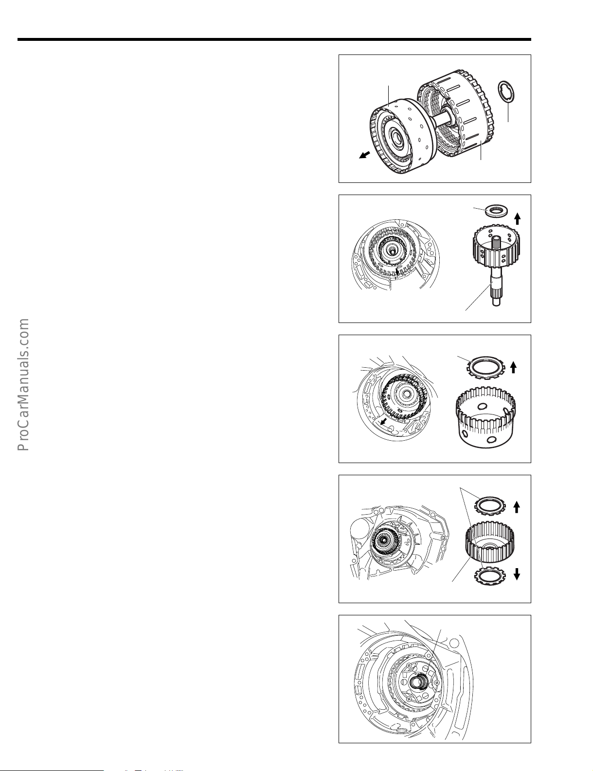
2. Confirmation of turning effort of rear clutch disc
(1) Install the thrust needle bearing to the rear multiple
clutch assembly, in the right direction.
(2) Assemble the intermediate shaft subassembly. Ensure
that the clutch discs rotate smoothly.
3. Measure the bush inner diameter of the front multiple
clutch assembly, using an inner caliper gauge.
Specified Value: 44.50 - 44.53 mm
Allowable Limit: 44.58 mm
NOTE:
• Ensure that the measurement should be performed at
several points.
• If the measured value exceeds the allowable limit, re-
place the front multiple clutch assembly with a new
one.
4. Confirmation of turning effort of front multiple clutch assembly
(1) Insert the rear multiple clutch assemble to the front
multiple clutch assembly, with the 3 new oil seal rings
assembled.
NOTE:
• Be careful not to damage the seal rings of the rear mul-
tiple clutch assembly, with the 3 new oil seal rings
JAT00055-00054
JAT00056-00055
JAT00057-00056
Page 27
AT–18
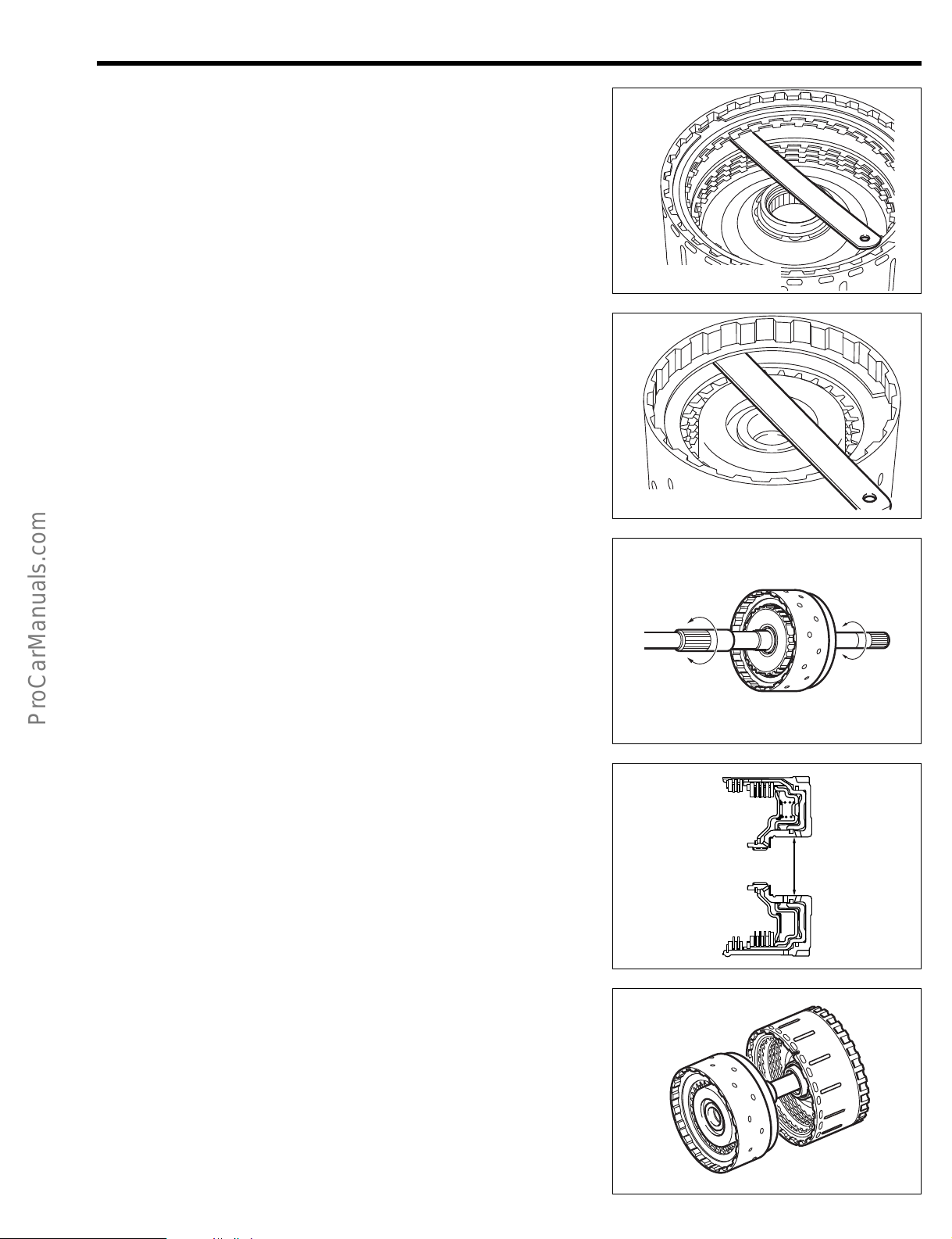
(2) Install the thrust needle bearing to the rear multiple
clutch assembly, in the right direction.
(3) Assemble the forward clutch hub. Ensure that it rotate
smoothly.
(4) Install the thrust needle bearing to the rear multiple
clutch assembly, in the right direction.
(5) Assemble the planetary sun gear assembly. Ensure
that it rotate smoothly.
JAT00058-00057
ONE-WAY CLUTCH
Hold the planetary gear assembly and turn the one-way
clutch.
NOTE:
• Ensure that it turns freely when turned counterclockwise and locked when turns clockwise.
JAT00059-00058
JAT00060-00059
Page 28

ASSEMBLY
Brake flange
Brake plates
(4 pieces)
Brake discs
(4 pieces)
A
X
1st & reverse brake piston
1. Selection of brake flanges, snap rings for 1st & reverse
brake piston and 2nd & 4th brake piston
Before assembling the unit, determine the thickness of the
snap rings brake flanges, as follows.
(1) Assemble the piston, brake discs and brake plates as
shown in the right figure. Push them from the direction
A with a load of 4.9 to 7.8 N. (Place a suitable weight).
(2) Measure the dimension X with a height gauge. Based
on this dimension, select a suitable brake flange (1st &
Rev), snap ring (2nd & 4th) according to the table
below.
NOTE:
• The dimension X is the distance measured between
the following points.
• The dimension X shall be the maximum value among
values measured at three points on the circumference.
• If the variation of the three measured values exceed
0.2 mm, redo the measurement of the dimension of
each part.
1st & Rev.: Brake disc end and brake piston end sur-
face
2nd & 4th: Brake flange end and brake piston end
surface
Brake plates
(2 pieces)
Brake
flanges
(2 pieces)
X
2nd & 4th brake piston
AT–19
JAT00131-00128
A
Brake discs
(3 pieces)
JAT00132-00129
Table Showing Availability of Brake Flanges for 1st &
Reverse Brake Piston
No.
1
2
3
4
5
6
Dimension X
39.45 - 39.661
39.25 - 39.45
39.05 - 39.25
38.85 - 39.05
38.65 - 38.85
38.439 - 38.65
Table Showing Availability of Snap Rings for 2nd & 4th Brake Piston
No.
1
2
3
4
Dimension X
35.854 - 36.11
36.11 - 36.36
36.36 - 36.61
36.61 - 36.866
Part number
35885-97201
35885-97202
35885-97203
35885-97204
35885-97205
35885-97206
Part number
90045-21179
90045-21178
90045-21177
90045-21176
Thickness
4.0
4.2
4.4
4.6
4.8
5.0
Thickness
2.25
2.00
1.75
1.50
Identification color
Black
Brown
Blue
Silver
JAT00133-00000
Page 29
AT–20
Speedometer
drive gear
A4R-D1
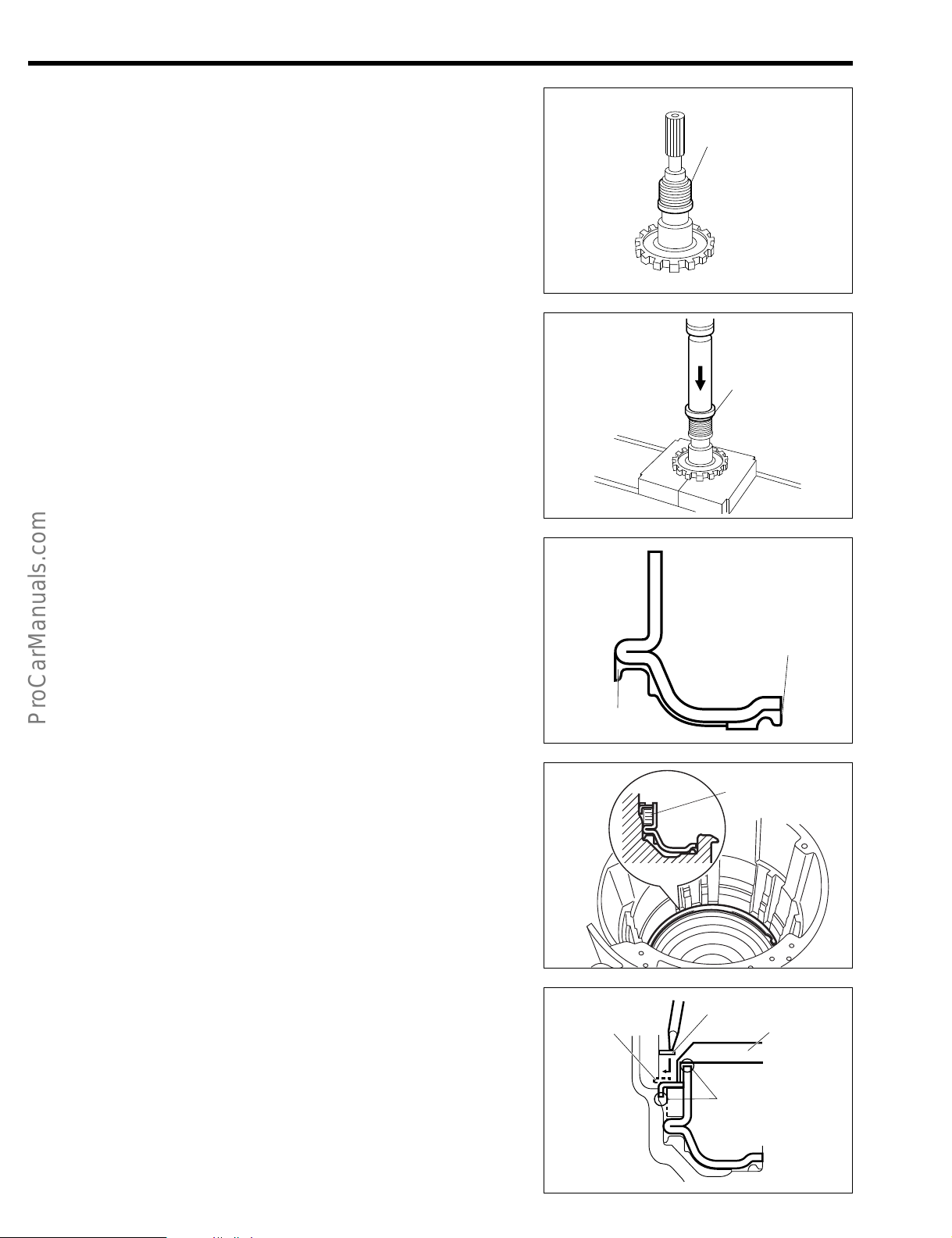
2. Assembly of output shaft
(1) Insert the speedometer drive gear to the output shaft.
[A4R-D1]
(2) Temporally insert a new radial ball bearing to the out-
put shaft. Press the bearing in place, using a press in
combination with the following SST given below.
SST: 09309-87201-000
JAT00061-00060
Bearing
3. Assembly of 1st & reverse brake piston.
(1) Apply ATF to the outer and inner periphery of the new
brake piston and to the inserted section of brake piston of the transmission case.
(2) Insert the new brake piston, piston return spring, and
piston return spring seat into the transmission case.
(3) Temporarily assemble the hole snap ring on the return
spring seat using snap ring pliers.
(4) Compress the piston return spring seat, using the fol-
lowing SST.
SST: 09351-97201-000, 09350-87202-000
Apply ATF
Groove
JAT00062-00061
Apply ATF
JAT00063-00062
Spring
JAT00064-00063
Snap ring
SST
NOTE:
• To prevent deformation, be sure to stop tightening the
SST when the spring has been lowered 1 to 2 mm from
the snap ring installation groove.
• Do not expand the ring excessively.
• The hole snap ring will become a center guide for the
SST.
Deformation
JAT00065-00064
Page 30
(5) Install the hole snap ring, using a flat screwdriver. And
Spring
remove the SST.
(6) Install the parking lock pawl shaft and the parking lock
pawl to the transmission case.
(7) Install the torsion spring, as indicated in the right fig-
ure.
NOTE:
• Push the parking lock pawl and release it. At this time,
make sure that the pawl returns to the original position.
AT–21
JAT00066-00065
Spring
4. Measure the inner diameter of the planetary output shaft
subassembly, using an inner caliper gauge.
Specified Value: 13.00 - 13.02 mm
Allowable Limit: 13.07 mm
NOTE:
• Perform the measurement at several points. Calculate
the mean value.
• If the measured value exceeds the allowable limit, re-
place the planetary output shaft subassembly with a
new one. Moreover, when replacing it, be sure to check
the bush contacting surface of the planetary output
shaft subassembly for scratch or discoloration. If the
surface is scratched or discolored, replace the planetary output shaft subassembly with a new part.
5. Installation of planetary output shaft subassembly.
(1) Install the radial ball bearing to the transmission case.
Parking lock pawl shaft Parking lock pawl
JAT00067-00066
Inner
diameter
JAT00068-00067
SST
Bearing
(2) Insert the planetary output shaft subassembly into the
radial ball bearing with your hand.
(3) Drive the reduction drive shaft subassembly, using the
following SSTs, and a press.
SSTs: 09309-87301-000 (A)
09636-20010-000 (B)
JAT00069-00068
SST (B)
Planetary
output shaft
SST (A)
JAT00070-00069
Page 31
AT–22
6. Installation of extension housing [2WD], side cover [4WD]
(1) Insert the extension housing bush apply tube to the
extension housing. [2WD]
(2) Thoroughly remove any foreign matters (seal bond,
grease, water, etc.) from both the mating surfaces.
(3) Apply Three Bond TB1281B to the surface of the trans-
mission case in such a way that a sealing may be
formed without any discontinued spot, in a size equivalent to a 0.5 mm to 1.5 mm diameter, following the
procedure given in the right figure.
NOTE:
• If the seal bond is applied in an excessive amount, the
sealing agent may mix with the ATF, resulting in a restricted strainer. Therefore, care must be exercised not
to apply the seal bond excessively.
JAT00071-00070
2WD
JAT00072-00071
4WD
(4) Tighten the 8 bolts of the extension subassembly.
[2WD]
Tighten the 10 bolts of the side cover. [4WD]
Tightening Torque: 14.7 - 21.6 N·m
NOTE:
• Be sure to tighten the bolts alternately and diagonally.
• In the case of A4Q-D1, be sure to tighten the bolts lo-
cated at the (A)-marked points.
7. Installation of the transfer assembly [4WD]
(1) Install the oil guide plate to the side cover by tighten-
ing the 2 bolts.
Tightening Torque: 6.9 - 9.8 N·m
(2) Install the transfer by tightening the 7 bolts.
Tightening Torque: 29.4 - 44.1 N·m
NOTE:
• Be sure to tighten the bolts alternately and diagonally
• In the case of A4Q-D1, be sure to tighten the bolts lo-
cated at the (A)-marked points.
• The numeral in the right figure indicates the nominal
length of the bolt.
JAT00000-00130
2WD
(A)
(A)
JAT00073-00072
4WD
(A)
(A)
JAT00000-00131
Page 32
8. Installation of 1st & reverse brake
P P P P
F
D D D D
Piston side
(1) Install the brake flanges, plates and discs in the follow-
ing order.
F = Brake flange, P = Brake plate, D = Brake disc
P → D → P → D → P → D → P → D → F
NOTE:
• Before assembling new discs, soak them in the ATF for
at least two hours.
• Be sure to align the cut-out section of the brake plates
and flange stalling the brake plate.
• Install a new hole snap ring to the grooved section of
the transmission case.
AT–23
JAT00074-00073
Cut-out section
9. Install the planetary gear assembly.
(1) Install the thrust needle roller bearing to the planetary
output shaft subassembly.
Reference Value:
Thrust Needle Roller Bearing Dimension:
Refer to page AT–5
NOTE:
• Be sure to install the (B) section of the bearing faces
toward the output shaft side.
(2) Apply ATF to the surface of each gears and install the
planetary gear assembly.
NOTE:
• Ensure that the assembly rotates smoothly.
10. Installation of one-way clutch
(1) Coat the sliding section of the one-way clutch with the
ATF.
(2) Install the one-way clutch.
NOTE:
• Ensure that the one-way clutch with the snap ring faces
toward the upside.
• Align the cut-out section at the inside of the transmis-
sion case with the protruding section provided with the
match mark of the one-way clutch.
JAT00000-00074
Bearing
Output shaft
(B)
JAT00075-00075
JAT00076-00076
Cut-out section
JAT00077-00077
Page 33

AT–24
11. Installation of the 2nd & 4th piston
(1) Apply ATF to the outer periphery of the new brake pis-
ton and to the inserted section of brake piston of the
transmission case.
(2) Assemble the 2nd & 4th piston and cylinder.
NOTE:
• Be sure to insert the piston vertically.
(3) Insert the new brake piston subassembly, piston return
spring into the transmission case.
(4) Insert the piston return spring seat in the right direction.
(5) Assemble the hole snap ring using snap ring pliers
and 2 flat screwdrivers.
NOTE:
• Be sure to align the cut-out section of the brake plate
with the protruding section of the transmission when in-
stalling the brake plate.
• Make sure to assemble the snap ring in such a way
that its end gaps face upward of the unit.
12. Installation of 2nd & 4th brake
(1) Install the brake flanges, plates and discs in the follow-
ing order.
F = Brake flange, P = Brake plate, D = Brake disc
F → D → P → D → P → D → F
NOTE:
• Before assembling new discs, soak them in the ATF for
at least two hours.
• Be sure to align the cut-out section of the brake plate
with the protruding section of the transmission when installing the brake plate.
• Install a new hole snap ring to the grooved section of
the transmission case.
JAT00078-00078
JAT00079-00079
JAT00080-00080
1st & Rev.
13. Measurement of 1st & reverse brake and 2nd & 4th brake
end play
(1) Turn over the transmission case.
(2) Measure the 1st & reverse brake and 2nd & 4th brake
end play, using a flat thickness gauge.
Specified Value:
1st & Reverse Brake: 0.69 - 1.18 mm
2nd & 4th Brake: 1.08 - 1.53 mm
NOTE:
• The tightness which you encounter during this inser-
tion/withdrawal of the flat thickness gauge should be
virtually the same as the tightness which you would encounter during the thickness adjustment of the valve
rocker arm.
• If the measured end play fails to conform to the speci-
fied value above, select a snap ring from the table, of
the step 1.
2nd & 4th
Thickness
gauge
JAT00081-00081
Page 34
14. Installation of rear planetary sun gear subassembly
(1) Measure the bush bore diameter of the rear planetary
sun gear subassembly.
Specified Value: 18.00 - 18.02 mm
Allowable Limit: 18.07 mm
NOTE:
• The measurement should be performed at several
points. Determine the mean value.
• If the bore diameter exceeds the allowable limit, re-
place the rear planetary sun gear subassembly.
• When replacing the rear planetary sun gear subassem-
bly, be sure to check the bush contacting surface of the
intermediate shaft subassembly. If the contacting surface is scored or discolored, replace the intermediate
shaft subassembly, too, with a new one at the same
time.
AT–25
JAT00083-00083
(2) Install the rear planetary sun gear subassembly to the
planetary gear assembly.
NOTE:
• Apply ATF to the bush section.
15. Measure the bush inner diameter of the front multiple
clutch assembly, using an inner caliper gauge.
Specified Value: 44.50 - 44.53 mm
Allowable Limit: 44.58 mm
NOTE:
• Ensure that the measurement should be performed at
several points.
• If the measured value exceeds the allowable limit, re-
place the front multiple clutch assembly with a new
one.
JAT00084-00084
JAT00056-00055
Page 35
AT–26
16. Installation of the front planetary sun gear assembly, forward clutch hub and intermediate shaft subassembly
(1) Measure the bush bore diameter of the planetary sun
gear subassembly.
Specified Value: 27.00 - 27.02 mm
Allowable Limit: 27.07 mm
NOTE:
• The measurement should be performed at several
points. Determine the mean value.
• If the bore diameter exceeds the allowable limit, re-
place the planetary sun gear subassembly.
• When replacing the planetary sun gear subassembly,
be sure to check the bush contacting surface of the
rear planetary sun gear subassembly. If the contacting
surface is scored or discolored, replace the rear planetary sun gear subassembly with a new one, too, at the
same time.
(2) Assemble the front planetary sun gear assembly with
the two thrust needle roller bearings to the planetary
gear assembly.
NOTE:
• Apply ATF to the bush section.
• Make sure that the two thrust needle roller bearings are
assembled in the correct direction.
• Assemble by aligning the pawls of the clutch disc of the
2 & 4 brake with the groove of the planetary sun gear
assembly hub
JAT00085-00000
REFERENCE:
• Dimensions of thrust needle roller bearing: Refer to
page AT–5.
(3) Assemble the forward clutch hub with the thrust nee-
dle roller bearing to the planetary sun gear assembly.
NOTE:
• Apply ATF to the forward clutch hub.
• Make sure that the thrust needle roller bearing is as-
sembled in the correct direction.
REFERENCE:
• Dimensions of thrust needle roller bearing: Refer to
page AT–5.
(4) Assemble the Intermediate shaft subassembly with the
thrust needle roller bearing to the forward clutch hub.
NOTE:
• Apply ATF to the Intermediate shaft subassembly.
• Make sure that the thrust needle roller bearing is as-
sembled in the correct direction.
REFERENCE:
• Dimensions of thrust needle roller bearing: Refer to
page AT–5.
JAT00086-00085
JAT00087-00086
JAT00088-00087
Page 36

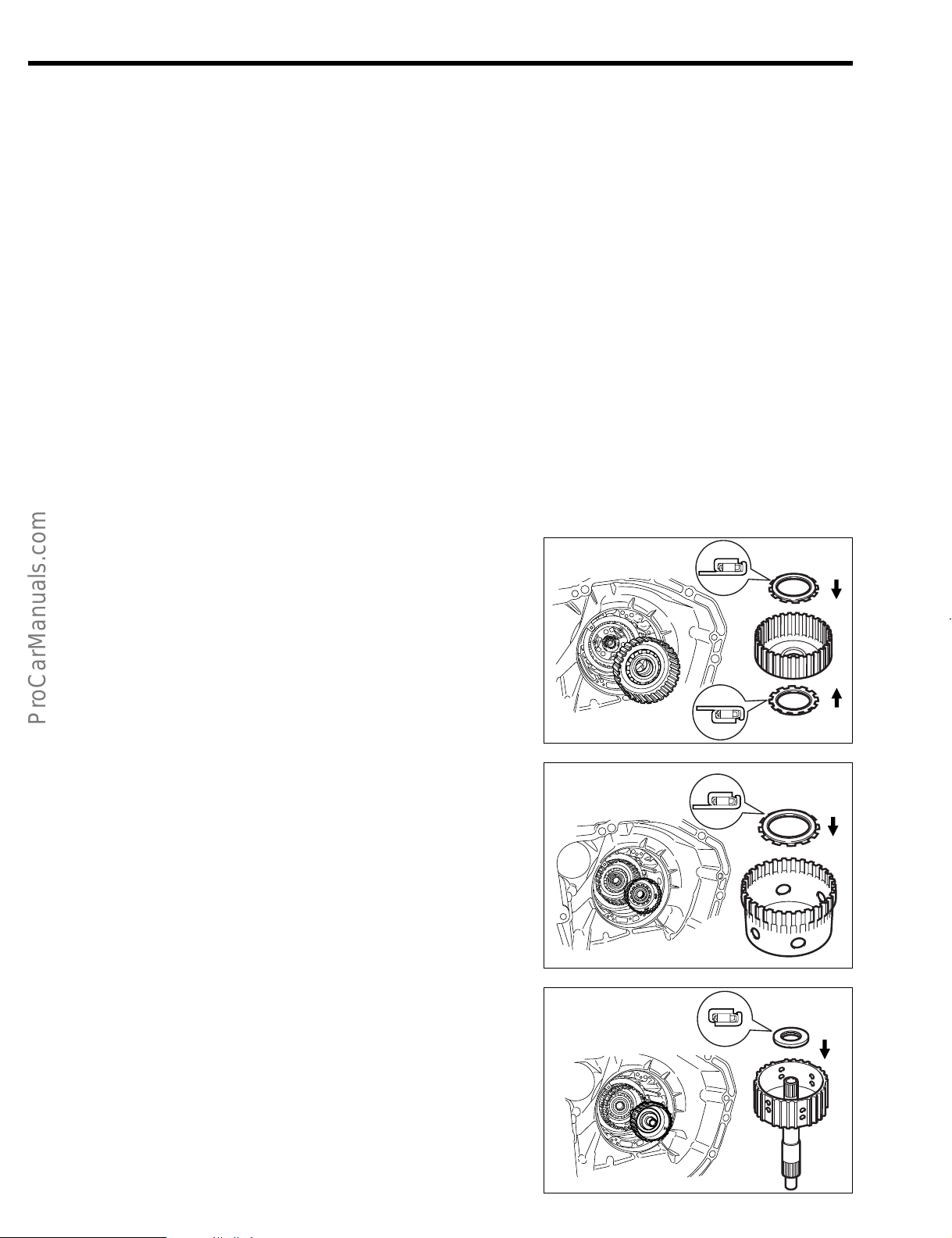
17. Installation of the rear multiple clutch assembly
Align the pawls of the clutch disc of the rear multiple
clutch assembly with each other.
Assemble the rear multiple clutch by aligning the pawls of
the clutch disc of the rear multiple clutch assembly with
the groove of the forward clutch hub and with the groove
of the intermediate shaft subassembly.
18. Measure the height of the rear multiple clutch assembly
between the installation section of the oil pump using the
following SST & vernier calipers.
SST: 09350-87202-000 (09351-87208-000)
Specified Value: Approx. 43 mm
Dimension X: Distance between oil pump contact
surface and rear multiple clutch assembly.
AT–27
JAT00089-00088
Vernier calipers
SST
Seal rings
X
NOTE:
• If the measured value is less than 43 mm, the pawl
section of the forward clutch disc is probably not fitted
in the groove of the forward clutch hub. Be sure to perform the operation of the step again.
• Do not touch the seal rings.
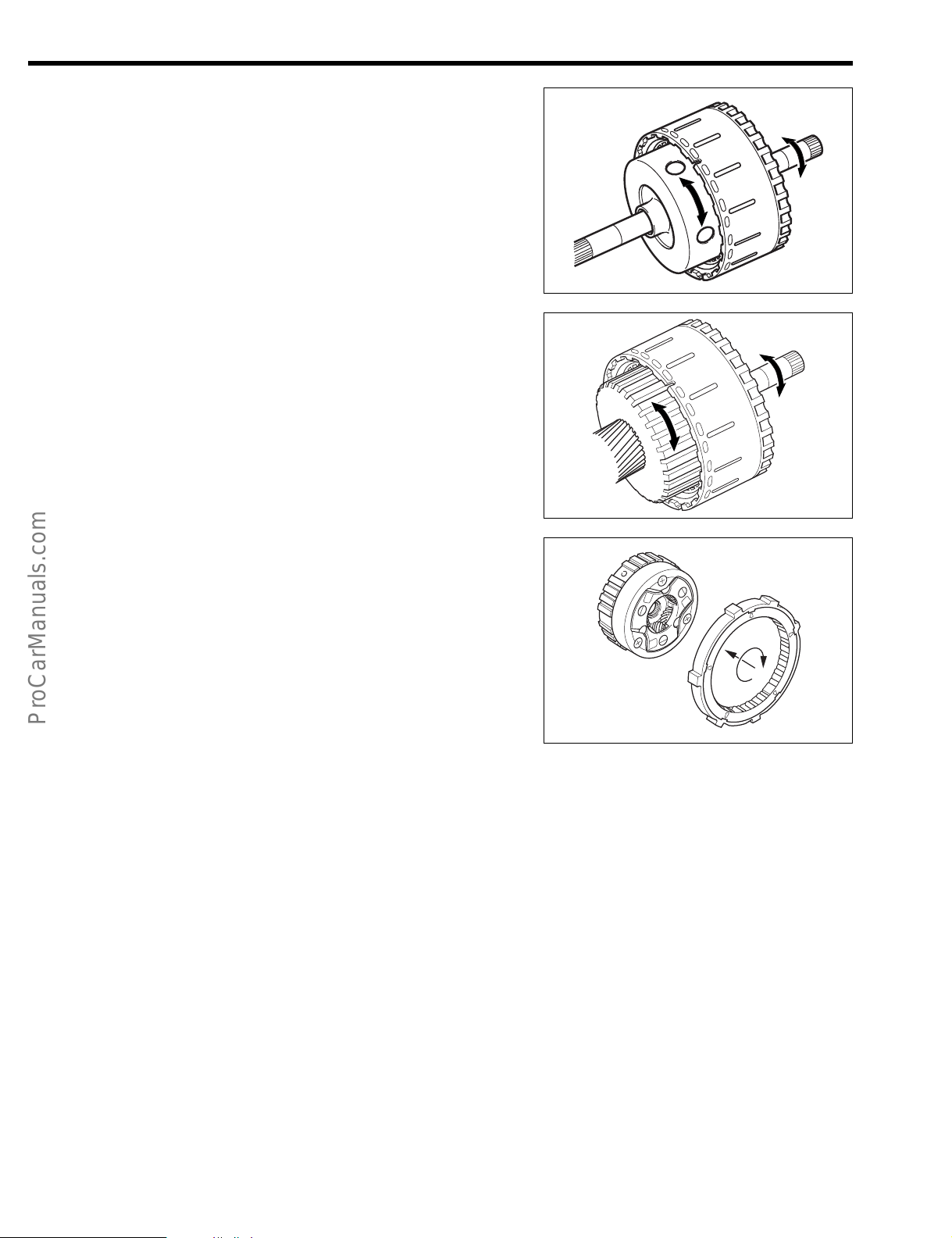
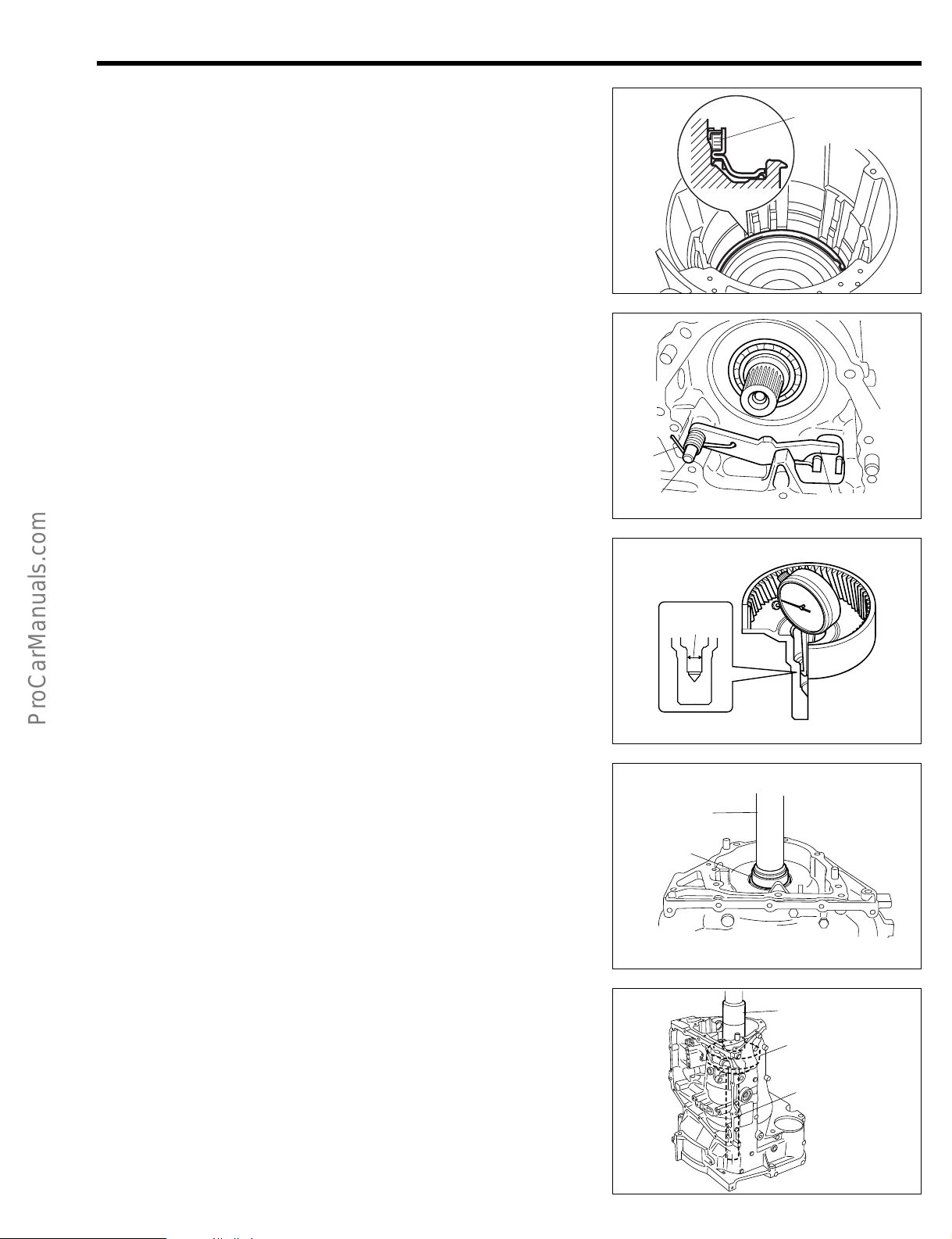
19. Turn the forward clutch clockwise and counterclockwise.
At this time, ensure that the forward clutch turns lightly
and the planetary sun gear assembly makes a relative
movement with the forward clutch.
JAT00090-00135
20. Installation of front multiple clutch assembly
(1) Measure and record the thickness of the thrust needle
roller bearing.
(2) Install the front multiple clutch assembly to the forward
clutch drum and the planetary sun gear assembly as
turning clockwise and counterclockwise.
NOTE:
• Be careful not to damage the seal rings of the rear mul-
tiple clutch assembly.
JAT00091-00089
JAT00092-00090
Page 37

AT–28
X
(3) Confirm the height of the oil pump attaching surface
from the front multiple clutch assembly upper surface,
using the following SST.
SST: 09350-87202-000 (09351-87208-000)
Specified Height: Approx. 43.5 mm
Dimension X: Distance between oil pump contact
surface and rear multiple clutch assembly.
NOTE:
• Perform the measurement at several points. Calculate
the mean value.
• If the measured value is less then 43.5 mm, the two
pawls of the clutch disc are probably not fitted into the
groove of the forward clutch drum or the planetary sun
gear assembly. Be sure to perform the operation of the
step (3) above again.
JAT00093-00091
(4) Install the thrust roller bearing into the front multiple
clutch assembly.
NOTE:
• Make sure that the thrust needle roller bearing is assembled in the correct direction.
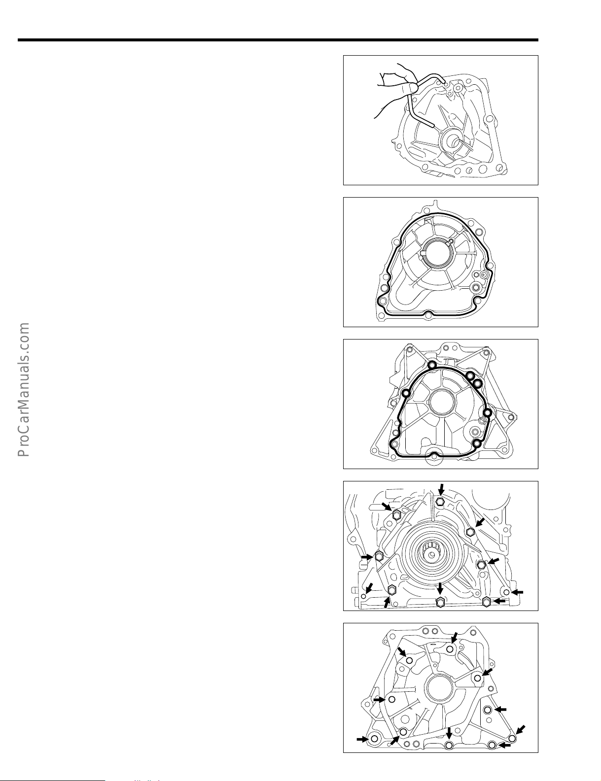
21. Inspection of stator shaft & oil pump assembly
(1) Inspection of oil pump operation
Ensure that the oil pump drive gear rotates smoothly,
using the following SST.
SST: 09350-87202-000 (09351-87206-000)
NOTE:
• Be sure to insert the flat sections (2 points) of the SST
into the flat sections of the oil pump drive gear.
(2) Measure the inner diameter of the oil pump bush sec-
tion, using an inner caliper gauge.
Allowable Limit:
NOTE:
• Perform the measurement at several points. Calculate
the mean value.
• If the actually measured value exceeds the allowable
limit, replace the stator shaft & oil pump assembly with
a new one.
• When replacing it, be sure to check the bush contact-
ing surface of the input shaft subassembly. If the surface is scratched or discolored, replace the shaft with a
new one, too.
023.52 mm
Thrust bearing
Planetary gear side
JAT00094-00092
JAT00096-00000
Cut view
Inner diameter
JAT00097-00094
Page 38

22. Assembly of stator shaft & oil pump assembly
Thrust bearing thickness mm
3.41
3.81
4.21
90043-74044-000
90043-74043-000
90043-74045-000
Part No.
Brown
––
Black
Color
(1) Coat 3 new clutch drum oil seal rings with the ATF and
install it to the stator shaft & oil pump assembly.
NOTE:
• Do not spread the new oil seal rings excessively.
(2) Coat and install the new O-ring.
(3) Assembly the stator shaft & oil pump assembly, follow-
ing the procedure given in the steps 16–(1) through
16–(8).
23. Installation of stator shaft & oil pump assembly
(1) Install the following SST to the transmission case.
SST: 09350-87202-000 (09351-87207-000)
(2) Apply the ATF to the outer periphery of the stator shaft
& oil pump assembly and install it to the transmission
case.
NOTE:
• Be very careful not to damage or twist the O-ring dur-
ing the installation.
(3) Tighten the 7 bolts of the stator shaft & oil pump as-
sembly.
Tightening Torque: 6.9 - 9.8 N·m
AT–29
JAT00098-00095
SST
JAT00099-00096
NOTE:
• Be sure to tighten the bolts alternately and diagonally.
(4) Measure the input shaft end play with a dial gauge
and the following SST.
SST: 09350-87202-000 (09351-87210-000)
Specified Value: 0.26 - 0.88 mm
NOTE:
• If the measured end play exceeds the specified value,
remove the stator shaft & oil pump assembly and the
direct clutch from the transmission case. Then, select
the thickness of the thrust bearing race from the lower
table. Proceed to perform the operations of the steps
from 20–(4) to 23–(4).
Thrust bearing availability
JAT00101-00098
JAT00102-00099
JAT00135-00000
Page 39

AT–30
Parking lock pawl cam support.
Manual valve idle shaft
(A)
(B)
(C)
(5) Install a new T-type oil seal, using the following SST.
SST: 09310-87301-000
NOTE:
• Make sure that the T-type oil seal is in contact at right
angles with the assembly.
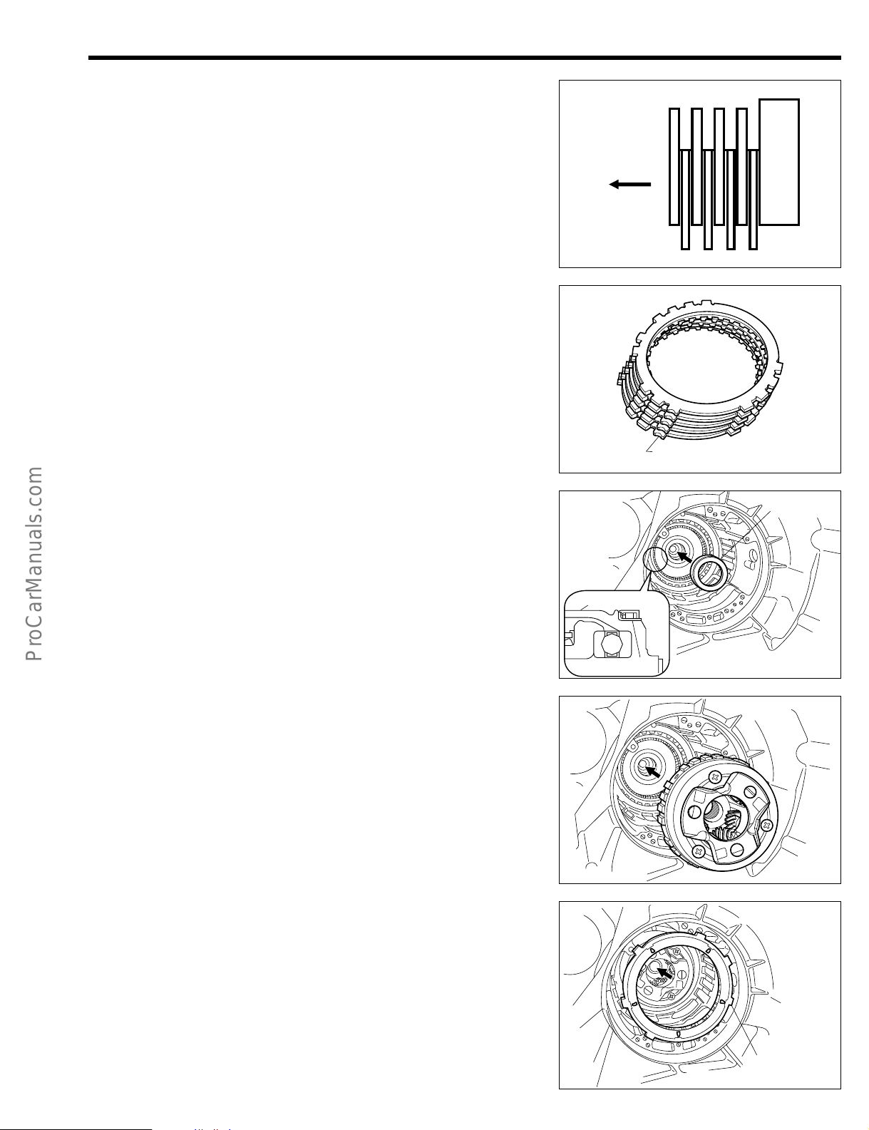
24. Installation of manual valve lever shaft assembly
(1) Install the parking lock pawl cam support and manual
valve idle shaft by first temporary tightening bolt (A).
Then tighten the bolts to the tightening torque in the
following order. Bolt (B) → (C) → (A)
Tightening Torque: 14.7 - 17.6 N·m
SST
JAT00103-00100
(2) Install the cut-out groove of the manual valve lever and
the protruding section of the parking lock rod to the
manual valve lever.
(3) Install the parking lock lever shaft subassembly from
the engine side.
(4) Install a new slotted spring pin, using a pin punch and
a hammer.
NOTE:
• Be sure to install the pin, until it reaches the edge sur-
face of the manual valve lever.
JAT00136-00133
JAT00104-00101
ATF
JAT00105-00102
JAT00138-00103
Page 40

(5) Install the the compression spring, bolt and plate.
ATF
Tightening Torque: 6.9 - 9.8 N·m
(6) Install the new 2nd & 4th brake cylinder seal.
25. Installation of the valve body assembly
(1) Assemble the manual valve idler plug (A) and manual
valve idler shaft.
NOTE:
• Ensure that the pin sections of the manual valve lever
subassembly (B) and the parking rod lever subassembly (C) are engaged with the groove section of the
manual valve idler plug.
• Ensure that each link moves smoothly.
(B)
AT–31
JAT00106-00104
(C)
ATF
(A)
ATF
(2) Install the valve body assembly to the transmission
case.
NOTE:
• Ensure that the protrusion of the manual valve lever (A)
and grooved section of the manual valve (B) are
matched securely.
• Align the forward end of the manual valve idler shaft
with the hole (C) of the valve body assembly.
(3) Tighten the 2 bolts with the (A) mark in the right figure,
and then tighten the other 5 bolts.
Tightening Torque: 6.9 - 9.8 N·m
NOTE:
• One bolt should be tightened together with the bracket.
• The numeral in the right figure indicates the nominal
length of the bolt.
(4) Ensure that the manual valve operates smoothly and
set it to the neutral position, using the following SST.
SST: 09350-87202-000 (09351-87211-000)
(C)
#5
#5
JAT00107-00105
(B)
(A)
ATF
JAT00108-00106
^5
#5
(A)
#5
#5
#5
JAT00109-00107
SST
JAT00110-00108
Page 41
AT–32
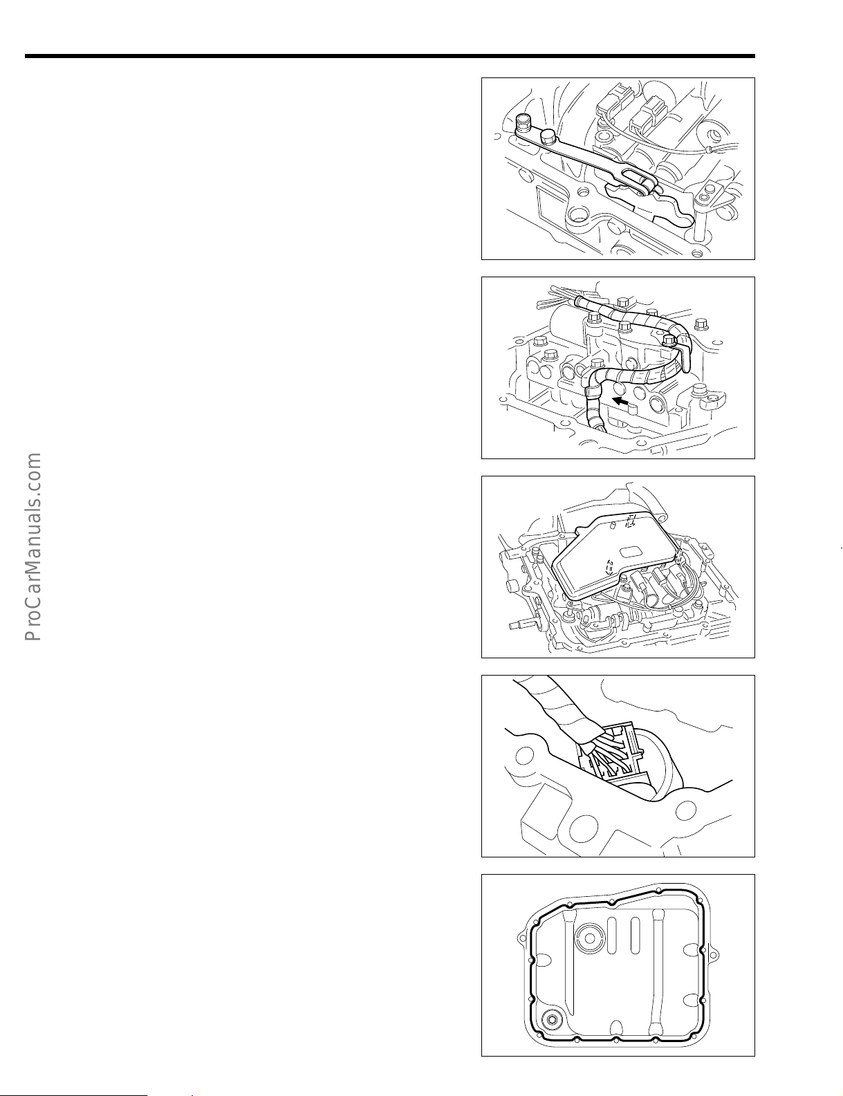
(5) Tighten the 2 bolts of the manual detent spring.
Tightening Torque: 6.9 - 9.8 N·m
NOTE:
• Be sure to tighten the bolts alternately.
(6) Attach the harness to the harness clamp.
JAT00111-00109
(7) Apply ATF to the new O-ring. Install the oil strainer with
the O-ring to the valve body assembly.
NOTE:
• Be sure that all 3 pawls are firmly set.
(8) Connect the transmission solenoid connector.
NOTE:
• Make sure that the pawls are firmly set.
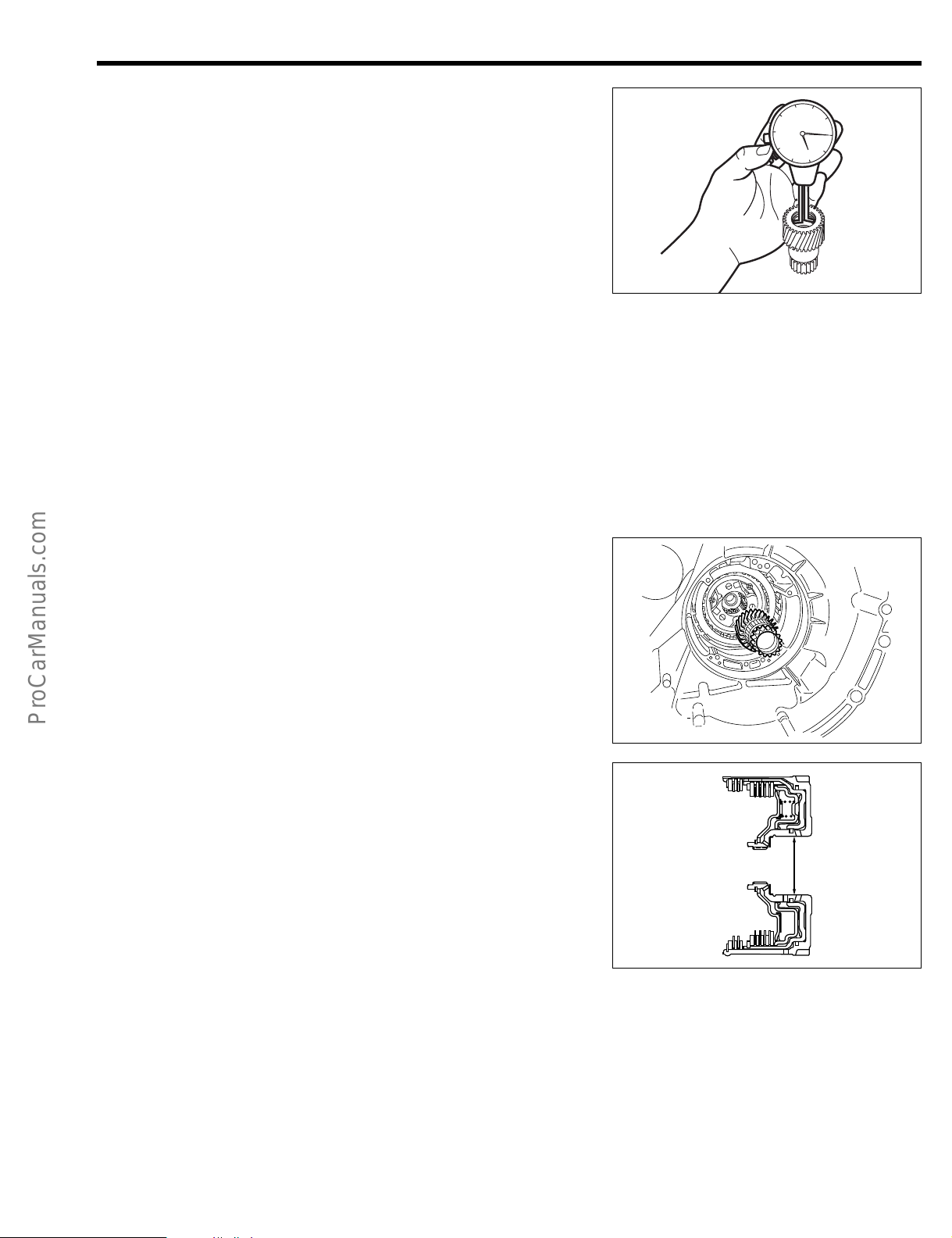
26. Installation of transmission oil pan subassembly
(1) Place the oil cleaner magnet in the protrusion of the
transmission oil pan subassembly.
(2) Toughly remove any foreign matter (grease and water,
etc.) from both the transmission case and the transmission oil pan subassembly
(3) Apply Three Bond TB1281B or equivalent to the sur-
face of the transmission case in such a way that a
sealing may be formed without any discontinued spot,
in a size equivalent to a 1.5 mm to 2.5 mm diameter,
following the procedure given in the right figure.
JAT00112-00110
JAT00113-00111
JAT00137-00134
JAT00114-00112
Page 42
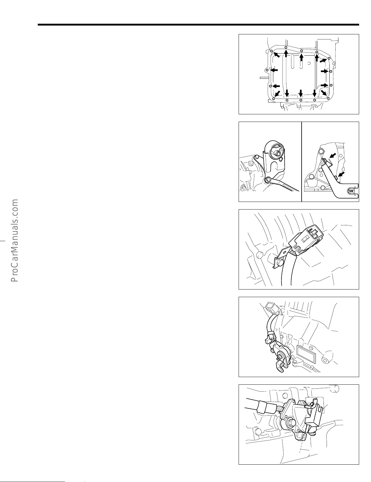
(4) Tighten the 14 bolts
Tightening Torque: 6.9 - 9.8 N·m
NOTE:
• Be sure to tighten the bolts alternately and diagonally.
27. Installation of the brackets.
Install the engine mount bracket by tightening the 3 bolts.
[A4R-D1 (2WD)]
Tightening Torque: 29.4 - 44.1 N·m
Install the control cable bracket by tighten the 2 bolts.
[A4Q-D1, A4R-D1 (4WD)]
Tightening Torque: 14.7 - 21.6 N·m
Engine mount bracket
A4R-D1 (2WD)
AT–33
JAT00115-00113
Coutrol cable bracket
A4Q-D1, A4R-D1 (4WD)
28. Tighten the bracket with the bolt and clamp the connector
of neutral start switch.
Tightening Torque: 6.9 - 9.8 N·m
NOTE:
• In the case of A4Q-D1, the direction of the coupler dif-
fers from that of A4R-D1.
29. Adjustment of neutral start switch
(1) Temporarily tighten the bolt of the neutral start switch
assembly.
(2) Place the transmission control shaft lever subassem-
bly.
(3) Push the lever toward the front side (ie: P range).
(4) Back off the lever two notches to the NEUTRAL posi-
tion.
(5) Remove the lever subassembly.
(6) Install the following SST.
SST: 09302-87201-000
(7) Adjust the neutral start switch assembly until the neu-
tral basic line on the SST should be aligned with SST
above.
(8) Tighten the bolt.
Tightening Torque: 14.7 - 21.6 N·m
JAT00124-00122
JAT00119-00117
JAT00116-00114
SST
Neutral basic line
JAT00117-00115
Page 43

AT–34
30. Tighten the lever subassembly with a nut.
Tightening Torque: 9.8 - 15.7 N·m
31. Installation of the 2 transmission revolution sensors.
(1) Coat the new O-ring section of the 2 transmission revo-
lution sensors with the ATF and insert the 2 transmission revolution sensors into the transmission case.
(2) Tighten the bolts
Tightening Torque: 6.9 - 9.8 N·m
JAT00118-00116
32. Install the speedometer shaft sleeve assembly. [A4R-D1]
(1) Coat the new O-ring section of the speedometer shaft
sleave assembly, and insert it to the transmission case.
(2) Tighten the bolt.
Tightening Torque: 6.9 - 9.8 N·m
33. Tighten the breather union and install the breather cap.
Tightening Torque: 2.9 - 9.8 N·m
34. Coat a new O-ring with the ATF and install it to the transmission oil filler tube subassembly.
NOTE:
• Be very careful not to twist or damage of the O-ring
during installation.
JAT00120-00118
JAT00121-00119
JAT00122-00120
35. Insert the transmission oil filler tube subassembly to the
transmission case and tighten it with the bolt.
Tightening Torque: 6.9 - 9.8 N·m
JAT00123-00121
Page 44

36. Install the transmission case assembly to the vehicle.
NOTE:
• Be sure to follow instructions in the AT section of the
Chassis Section of each model.
AT–35
JAT00125-00000
Page 45

AT–36
Shape Part No.
09302-87201-000
09301-87702-000
Gauge, neutral start switch adjust
Tool, clutch guide
Puller, oil seal
Replacer, counter shaft front bearing
Tool set, automatic transmission
Compressor, piston spring No. 1
Compressor, piston spring No. 2
Attachment, dial gauge
Compressor, spring
09308-10010-000
09310-87301-000
09350-87202-000
09351-87201-000
09351-87202-000
09351-87203-000
09351-87204-000
Part name
*It should be noted that 09350-87202 contains SSTs other than those posted in this section.
09351-87205-000
09351-87206-000
09351-87207-000
Holder, reduction drive gear holding
Driver, oil pump
Guide, oil pump
SST (Special Service Tools)
Page 46

AT–37
Shape Part No.
09351-87208-000
09351-87209-000
Measure, direct & forward clutch
Stopper, drive gear
Base, dial gauge stand
Tool, manual value setting
Holder, direct clutch
Gauge, centering side gear
Holder, ball bearing
Handle
09351-87210-000
09351-87211-000
09351-87212-000
09351-87213-000
09351-87214-000
09611-87506-000
Replacer, oil seal No. 809518-87709-000
Part name
*It should be noted that 09350-87202 contains SSTs other than those posted in this section.
09636-20010-000 Replacer, upper ball joint dust cover
Puller, alternator rear bearing
Puller, universal
09820-00021-000
09950-20017-000
Replacer, hole snap ring09351-97201-000
Page 47

AT–38
Shape Part No.
Bearing remover
Replacer, output shaft bearing
Replacer, oil seal No. 1
09950-87701-000
09309-87301-000
09517-87203-000
Replacer, oil seal No. 209517-87205-000
Remover & replacer, camshaft bearing09215-00101-000
Tool set, front hub & drive pinion bearing09608-30012-000
Part name
JAT00126-00123
Page 48
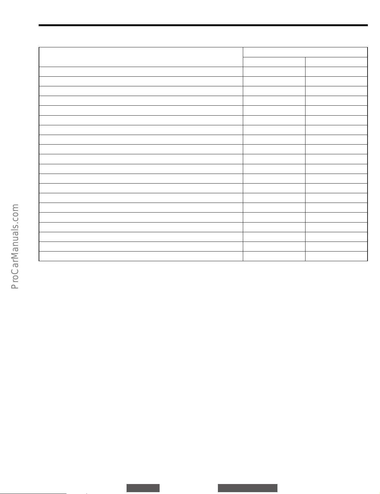
TIGHTENING TORQUE
Tightening torque
N·m kgf-m
Tightening components
Transfer × Side cover [4WD]
Side cover × Transmission case [4WD]
Oil guide plate × Side cover [4WD]
Extension × Transmission case [2WD]
Control cable bracket × Transmission case [A4Q-D1, A4R-D1 (4WD)]
Engine mount bracket × Extension [A4R-D1 (2WD)]
Speedometer sleeve lock plate × Transmission case [A4R-D1 (2WD)]
Stator shaft & oil pump × Transmission case
Oil pan × Transmission case
Drain plug × Oil pan
Valve body × Transmission case
Manual detent spring × Transmission case
Parking lock cam support × Transmission case
Neutral start switch × Transmission case
Transmission control shaft lever × NSS
Neutral start switch bracket × Transmission case
Transmission revolution sensor × Transmission case
Transmission solenoid connector × Transmission case
Oil filler tube × Transmission case
Breather plug union × Transmission case
29.4 - 44.1
14.7 - 21.6
6.9 - 9.8
14.7 - 21.6
14.7 - 21.6
29.4 - 44.1
6.9 - 9.8
6.9 - 9.8
6.9 - 9.8
19.6 - 29.6
6.9 - 9.8
6.9 - 9.8
14.7 - 17.6
14.7 - 21.6
9.8 - 15.7
6.9 - 9.8
6.9 - 9.8
6.9 - 9.8
6.9 - 9.8
2.9 - 9.8
3.0 - 4.5
1.5 - 2.2
0.7 - 1.0
1.5 - 2.2
1.5 - 2.2
3.0 - 4.5
0.7 - 1.0
0.7 - 1.0
0.7 - 1.0
2.0 - 3.0
0.7 - 1.0
0.7 - 1.0
1.5 - 1.8
1.5 - 2.2
1.0 - 1.6
0.7 - 1.0
0.7 - 1.0
0.7 - 1.0
0.7 - 1.0
0.3 - 1.0
TO INDEX TO NEXT SECTION
AT–39
JAT00127-00000
 Loading...