

Page 1

A1
B1
B2
B3
B4
B5
B6
B7
B8
B9
B10
B11
B12
C1
C2
C3
D2
E1
E2
E3
F1
F2
F3
F5
A.
GENERAL INFORMATION
B.ENGINE
C.SUSPENSION
D.DRIVELINE/AXLE
E.BRAKE
F. TRANSMISSION/
TRANSAXLE
GENERAL INFORMATION
ENGINE DESCRIPTION
ENGINE MECHANICAL
INTAKE SYSTEM
EXHAUST SYSTEM
LUBRICATION SYSTEM
COOLING SYSTEM
FUEL SYSTEM
ENGINE CONTROL SYSTEM
EMISSION CONTROL SYSTEM
IGNITION SYSTEM
STARTING SYSTEM/CHARGING SYSTEM
ENGINE MOUNTING
FRONT SUSPENSION
REAR SUSPENSION
WHEEL & TIRE
PROPELLER SHAFT/AXLE
BRAKE
PARKING BRAKE
BRAKE CONTROL
CLUTCH
MANUAL TRANSMISSION/MANUAL TRANSAXLE
AUTOMATIC TRANSMISSION/AUTOMATIC TRANSAXLE
TRANSMISSION CONTROL
Page 2
G1
G2
H1
I1
I2
I3
I4
J1
J2
J3
J4
J5
J6
K1
L2
G.STEERING
H.SRS AIRBAG
I.BODY
J.
BODY ELECTRICAL SYSTEM
K.
HEATER AND AIR CONDITIONER
L.
VEHICLE COMMUNICATIONS
STEERING
POWER STEERING
SRS AIRBAG SYSTEM
BODY
EXTERIOR/INTERIOR
WINDSHIELD WINDOWGLASS/MIRROR
DOOR LOCK & THEFT DETERRENT
LIGHTING
WIPER & WASHER
METER
AUDIO & VISUAL SYSTEM
WIRING
OTHER ELECTRICAL PARTS
HEATER & AIR CONDITIONER
MULTIPLEX COMMUNICATION SYSTEM
Page 3

CAN COMMUNICATION SYSTEM ------------ L2 - 1
OUTLINE ----------------------------------------- L2 - 1
DESCRIPTION ------------------------------- L2 - 1
SYSTEM DRAWING ----------------------- L2 - 1
SYSTEM WIRING DIAGRAM ------------ L2 - 3
LOCATION OF COMPONENTS--------- L2 - 8
CONTROL---------------------------------------- L2 - 9
COMMUNICATION CONTROL ---------- L2 - 9
COMMUNICATION PROTOCOL ------ L2 - 10
COMMUNICATION DATA---------------- L2 - 10
DIAGNOSIS (SELF-DIAGNOSIS)
FUNCTION----------------------------------- L2 - 11
FAIL-SAFE CONTROL ------------------- L2 - 11
COMPONENTS ------------------------------- L2 - 12
DLC-------------------------------------------- L2 - 12
TERMINATING RESISTANCE --------- L2 - 12
LIN COMMUNICATION SYSTEM ------------ L2 - 13
OUTLINE---------------------------------------- L2 - 13
DESCRIPTION ----------------------------- L2 - 13
SYSTEM DRAWING --------------------- L2 - 13
SYSTEM WIRING DIAGRAM ---------- L2 - 14
LOCATION OF COMPONENTS ------- L2 - 16
CONTROL -------------------------------------- L2 - 17
COMMUNICATION CONTROL -------- L2 - 17
WAKE-UP/SLEEP FUNCTION --------- L2 - 17
LIN COMMUNICATION PROTOCOL
(COMMUNICATION REGULATION)-- L2 - 18
DIAGNOSIS (ONBOARD
DIAGNOSIS FUNCTION)---------------- L2 - 18
FAIL-SAFE FUNCTION ------------------ L2 - 18
L2 MULTIPLEX COMMUNICATION SYSTEM
L2
TO INDEX
Page 4
ÄÄ
CAN COMMUNICATION SYSTEM
1OUTLINE
1-1 DESCRIPTION
1.A CAN
ŕg,DK_Mŧ
communication system which controls data relating to the power train at a higher speed
is used in all vehicles.
2.The CAN system sends over a single communications line (twisted pair cable) multiple items of information and data which have been converted into digital form by a communication circuit.
This system reduces the number of the wiring harnesses and the size of the electronic control system
for the systems that connect the input side (sensors, switches, etc.), the control units and the output
side (display lamps, etc.).
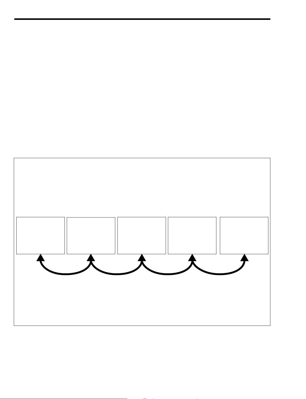
3.The CAN communication system in use is a daisy chain type network with several computers connected to a pair of communication lines.
NOTE
• ~1:CAN stands for Controller Area Network. It is the serial communication based on the ISO
standard (ISO011898).
1-2 SYSTEM DRAWING
1-2-1 RHD VEHICLES
T11E1201ES24
DLC
Meter
(Meter ECU)
Transmission
control computer
(A/T ECU)
Engine control
computer
(EFI ECU)
ABS actuator
(ABS ECU)
L2–1
Page 5
CAN communication connection system (RHD vehicles)
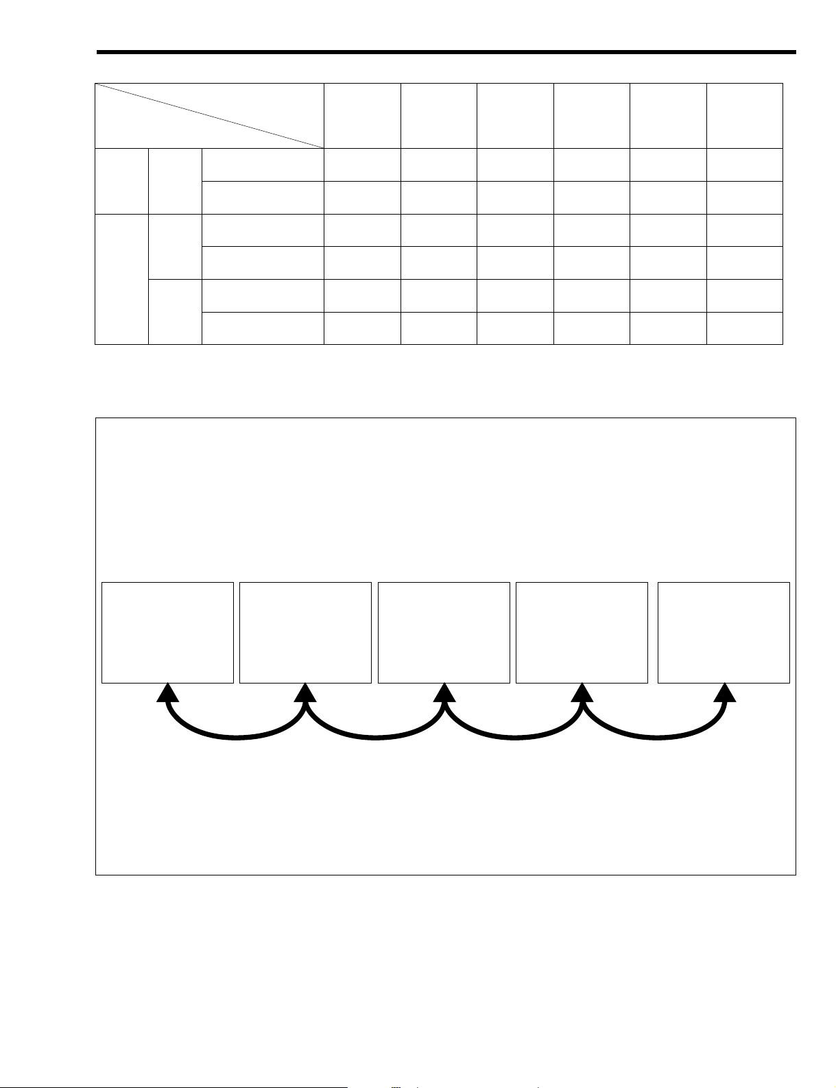
1-2-2 LHD VEHICLES
T11E1711ES24
DLC
Meter
(Meter ECU)
Transmission control
computer (A/T ECU)
Engine control
computer (EFI ECU)
ABS actuator
(ABS ECU)
ABS ECU A/T ECU EFI ECU Meter ECU DLC Name of
CAN com-
munication
system type
Vehicles not
equipped with ABS
((<<<Type 1 1KR M/T
ABS-equipped vehi-
cles
<(<<<Type 2
Vehicles not
equipped with ABS
((<<<Type 1 M/T
ABS-equipped vehi-
cles
<(<<<Type 2
Vehicles not
equipped with ABS
(<<<<Type 3
K3
A/T
ABS-equipped vehi-
cles
<<<<<Type 4
L2–2
Page 6
CAN communication connection system (LHD vehicles)
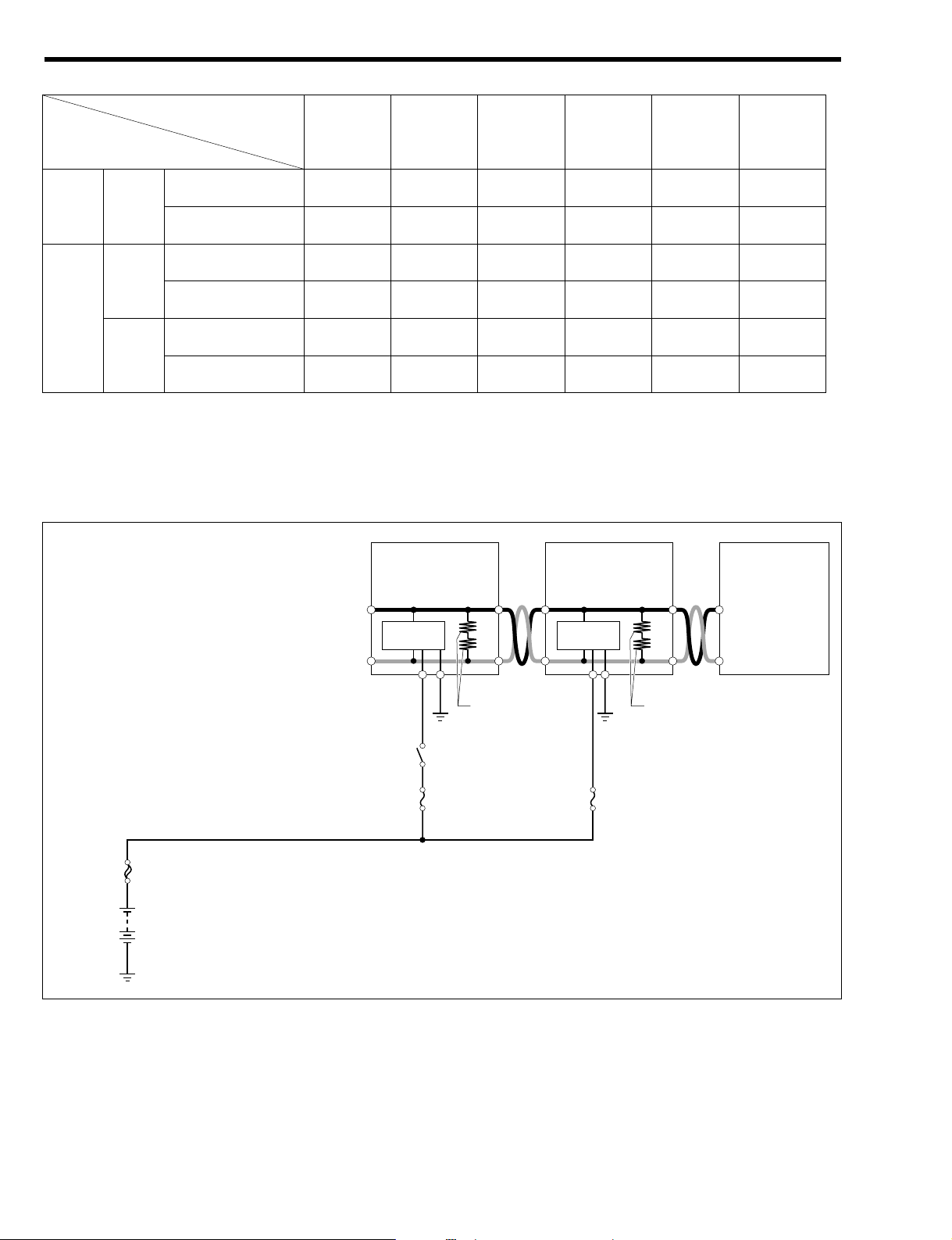
1-3 SYSTEM WIRING DIAGRAM
1-3-1 RHD VEHICLES
(1) Type 1
F/L
EFI BACK UP
Main relay
CAN
transceiver
CAN
transceiver
CANL
CANH
CANL 'B'BGND
CANH
LCAN
HCAN
CANL
CANH
Terminating resistance
(60+)
Terminating resistance
(60+)
LCANE1
HCAN
Battery
Engine control
computer (EFI ECU)
Meter (Meter ECU)
DLC
T11E1712ES22
ABS ECU A/T ECU Meter ECU EFI ECU DLC Name of
CAN com-
munication
system type
Vehicles not
equipped with ABS
((<<<Type 5 1KR M/T
ABS-equipped vehi-
cles
<(<<<Type 6
Vehicles not
equipped with ABS
((<<<Type 5 M/T
ABS-equipped vehi-
cles
<(<<<Type 6
Vehicles not
equipped with ABS
(<<<<Type 7
K3
A/T
ABS-equipped vehi-
cles
<<<<<Type 8
L2–3
Page 7
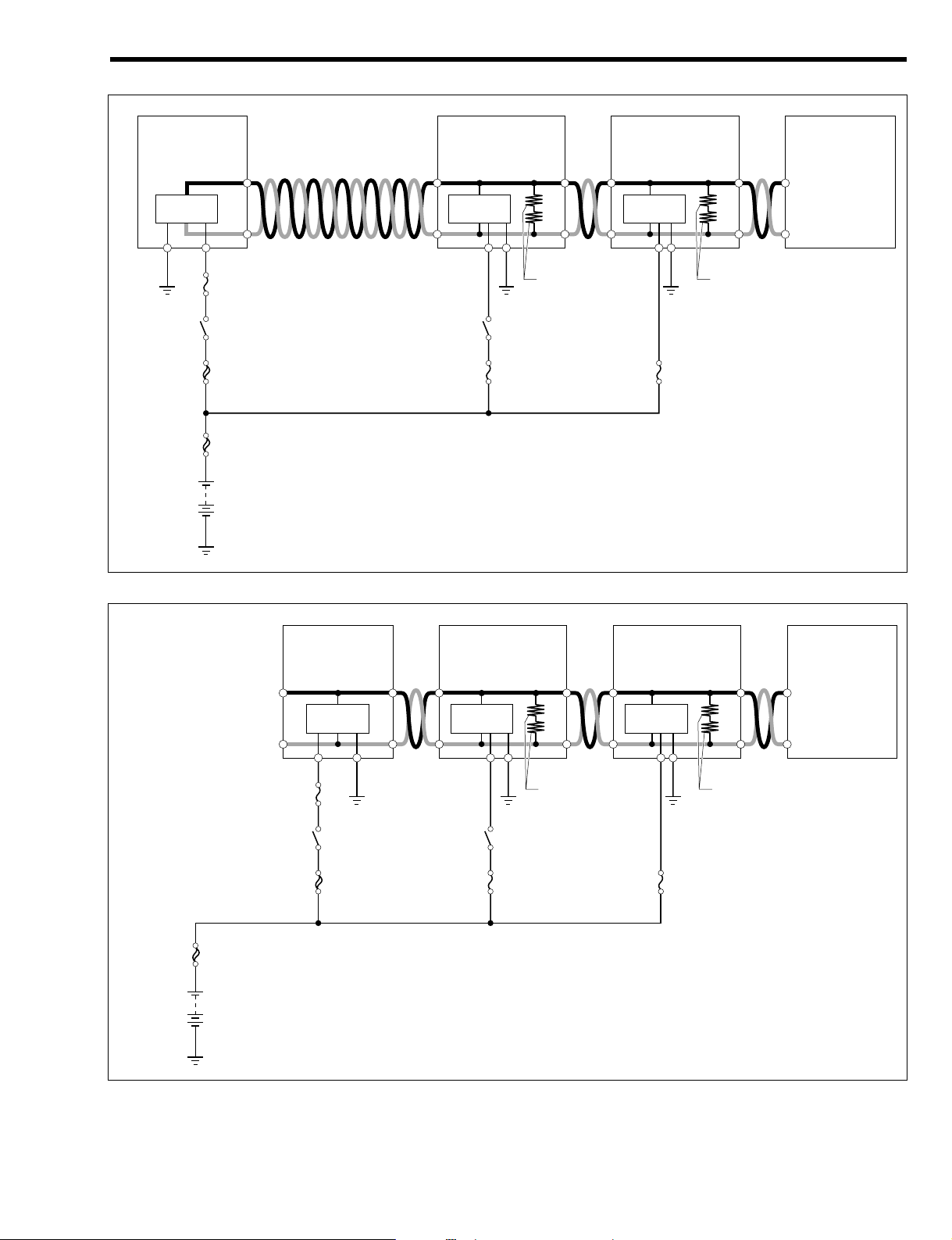
(2) Type 2
(3) Type 3
F/L
AM2 F/L EFI BACK UP
Main relay
CAN
transceiver
CAN
transceiver
CAN
transceiver
IG2 SW
ECU IG2
CANL
'B1 E1
CANH
LCN1
HCN1
CANL
CANH
CANL 'B'BGND
CANH
LCAN
HCAN
CANL
CANH
Terminating resistance
(60+)
Terminating resistance
(60+)
LCANE1
HCAN
Battery
Transmission control
computer (A/T ECU)
Engine control
computer (EFI ECU)
Meter
(Meter ECU)
DLC
T11E1714ES22
F/L
AM1 F/L
IG1 SW
ECU IG1
EFI BACK UP
Main relay
CAN
transceiver
CAN
transceiver
CAN
transceiver
GND 'IG LCAN
HCAN
CANL
CANH
CANL 'B'BGND
CANH
LCAN
HCAN
CANL
CANH
Terminating resistance
(60+)
Terminating resistance
(60+)
LCANE1
HCAN
Battery
ABS actuator
(ABS ECU)
Engine control
computer (EFI ECU)
Meter
(Meter ECU)
DLC
T11E1713ES22
L2–4
Page 8
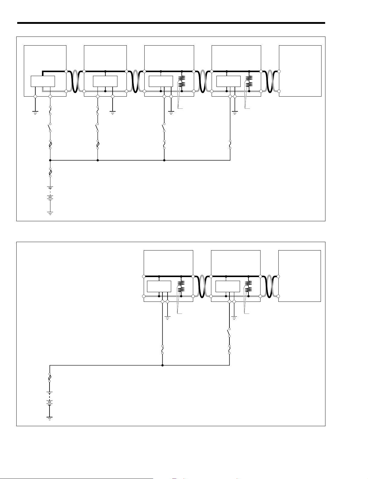
(4) Type 4
1-3-2 LHD VEHICLES
(1) Type 5
F/L
EFIBACK UP
Main relay
CAN
transceiver
CAN
transceiver
CANL
CANH
CANL 'B'BGND
CANH
LCAN
HCAN
CANL
CANH
Terminating resistance
(60+)
Terminating resistance
(60+)
LCAN E1
HCAN
Battery
Engine control
computer (EFI ECU)
Meter
(Meter ECU)
DLC
T11E1716ES22
F/L
AM1 F/L
IG1 SW
ECU IG1
AM2 F/L EFI BACK UP
Main relay
CAN
transceiver
CAN
transceiver
CAN
transceiver
CAN
transceiver
IG2 SW
ECU IG2
GND 'IG LCAN
HCAN
CANL
'B1 E1
CANH
LCN1
HCN1
CANL
CANH
CANL 'B'BGND
CANH
LCAN
HCAN
CANL
CANH
Terminating resistance
(60+)
Terminating resistance
(60+)
LCANE1
HCAN
Battery
ABS actuator
(ABS ECU)
Transmission control
computer (A/T ECU)
Engine control
computer (EFI ECU)
Meter
(Meter ECU)
DLC
T11E1715ES22
L2–5
Page 9

(2) Type 6
(3) Type 7
F/L
AM2 F/L EFIBACK UP
Main relay
CAN
transceiver
CAN
transceiver
CAN
transceiver
IG2 SW
ECU IG2
CANL
'B1 E1
CANH
LCN1
HCN1
CANL
CANH
CANL 'B'BGND
CANH
LCAN
HCAN
CANL
CANH
Terminating resistance
(60+)
Terminating resistance
(60+)
LCAN E1
HCAN
Battery
Transmission control
computer (A/T ECU)
Engine control
computer (EFI ECU)
Meter
(Meter ECU)
DLC
T11E1718ES22
F/L
AM1 F/L
IG1 SW
ECU IG1
EFIBACK UP
Main relay
CAN
transceiver
CAN
transceiver
CAN
transceiver
GND 'IG LCAN
HCAN
CANL
CANH
CANL 'B'BGND
CANH
LCAN
HCAN
CANL
CANH
Terminating resistance
(60+)
Terminating resistance
(60+)
LCAN E1
HCAN
Battery
ABS actuator
(ABS ECU)
Engine control
computer (EFI ECU)
Meter
(Meter ECU)
DLC
T11E1717ES22
L2–6
Page 10
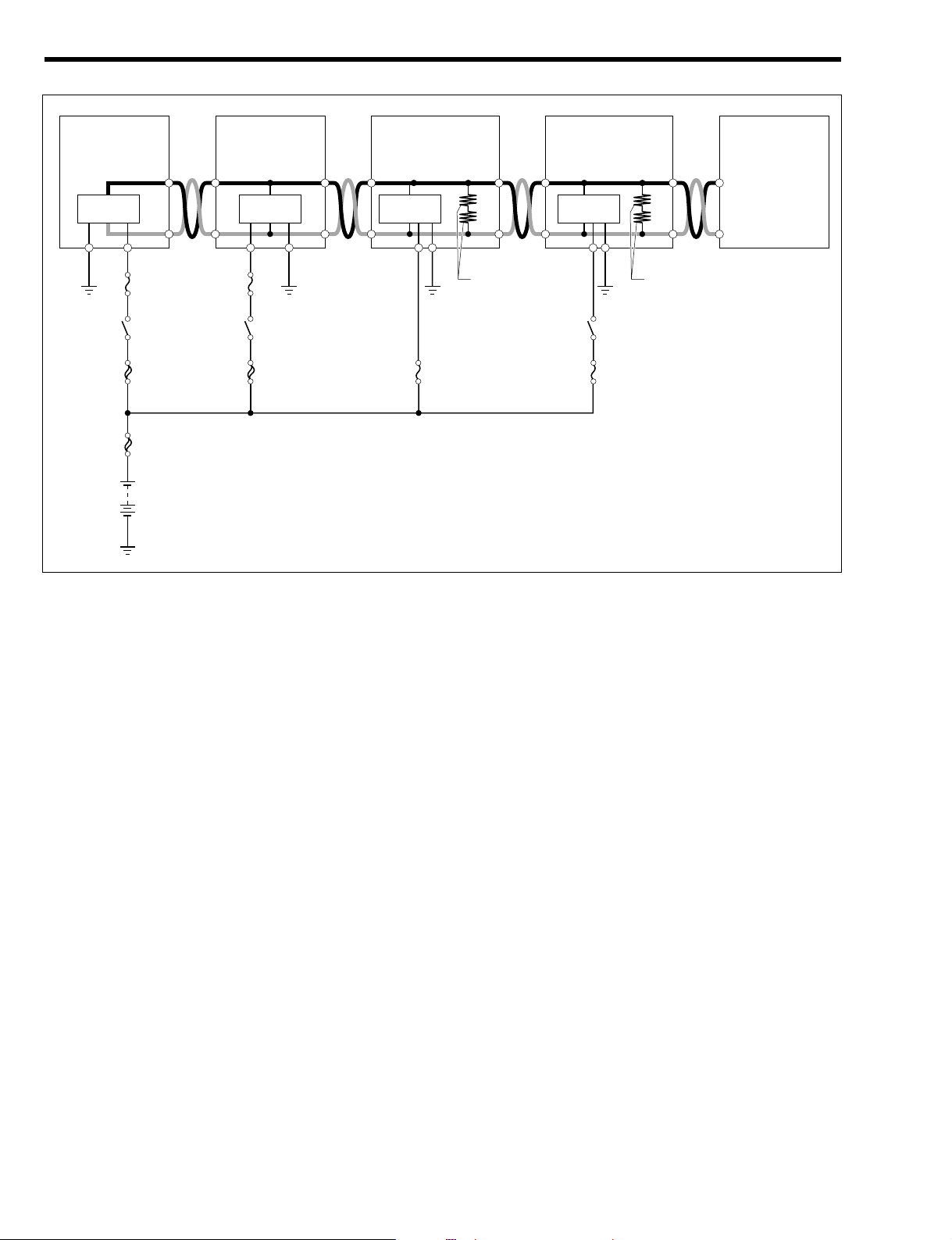
(4) Type 8
F/L
AM1 F/L
IG1 SW
ECU IG1
AM2 F/L EFIBACK UP
Main relay
CAN
transceiver
CAN
transceiver
CAN
transceiver
CAN
transceiver
IG2 SW
ECU IG2
GND 'IG LCAN
HCAN
CANL
'B1 E1
CANH
LCN1
HCN1
CANL
CANH
CANL 'B'BGND
CANH
LCAN
HCAN
CANL
CANH
Terminating resistance
(60+)
Terminating resistance
(60+)
LCAN E1
HCAN
Battery
ABS actuator
(ABS ECU)
Transmission control
computer (A/T ECU)
Engine control
computer (EFI ECU)
Meter
(Meter ECU)
DLC
T11E1719ES22
L2–7
Page 11
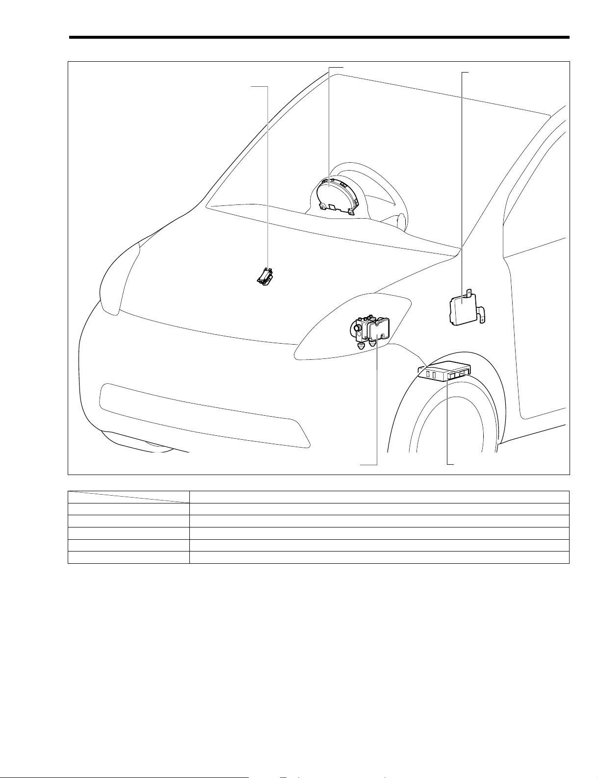
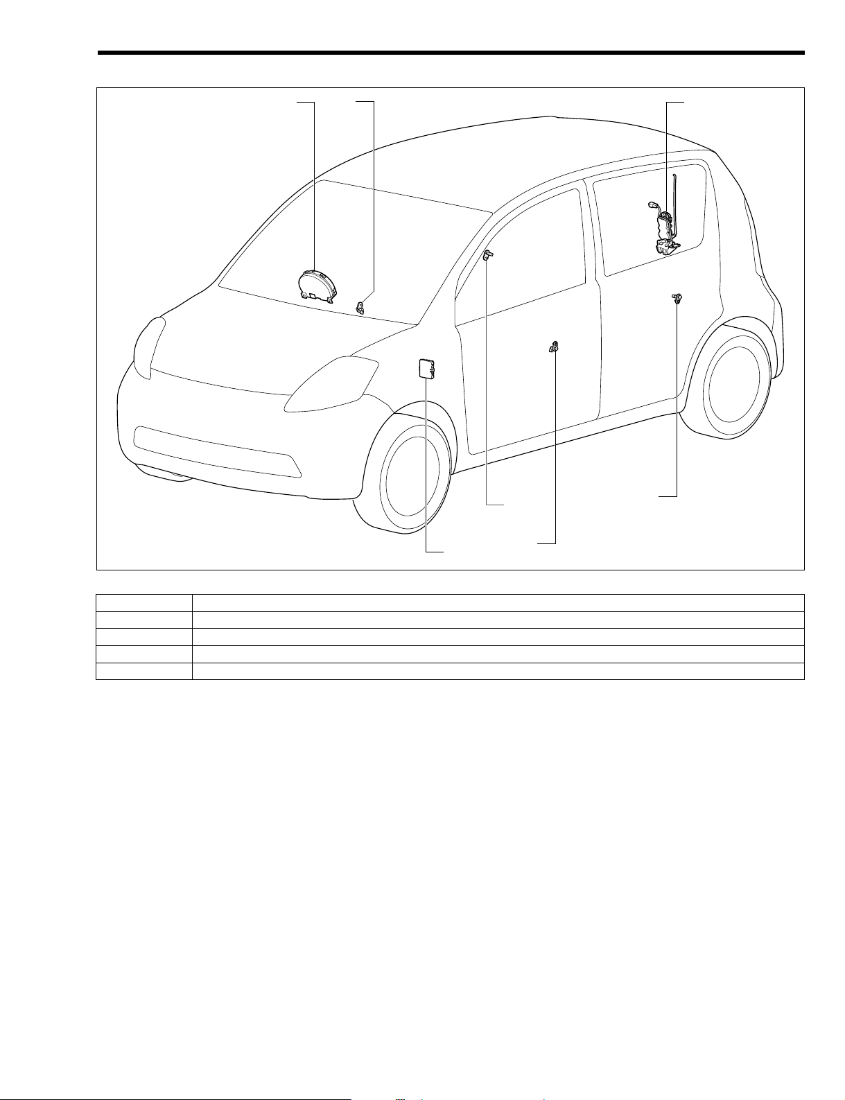
1-4 LOCATION OF COMPONENTS
The illustration show a right-hand drive vehicle.
Part name
a DLC
b Meter (meter ECU)
c Engine control computer (EFI ECU)
d Transmission control computer (A/T ECU)
e ABS actuator (ABS ECU)
T11E1203S30
a
b
d
e
c
L2–8
Page 12
2CONTROL
2-1 COMMUNICATION CONTROL
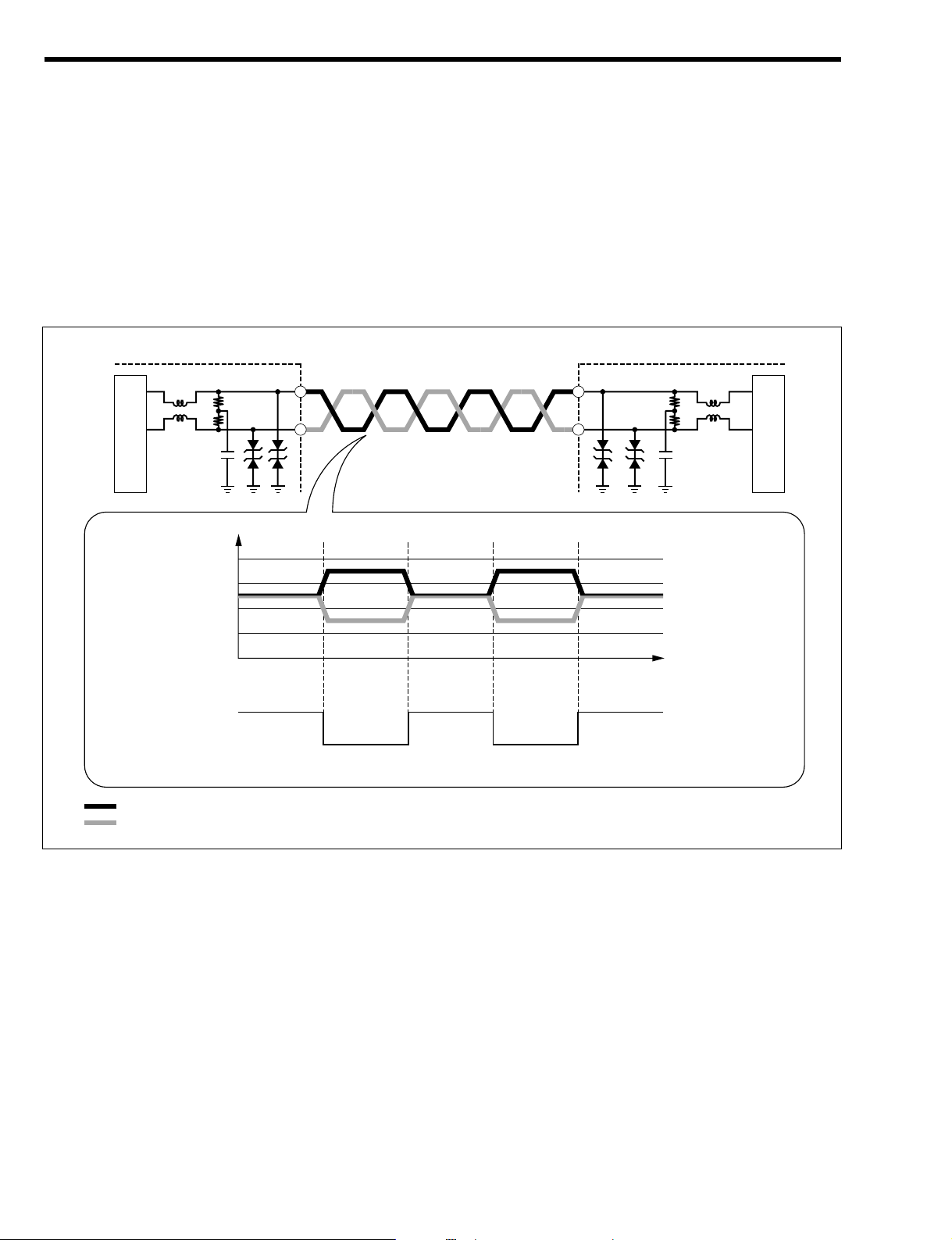
1. A CAN communication system has two communication lines (bus) acting as a pair and the bus level
ŕg,DK_Mŧŕg,DK_Mŧ
is determined by the voltage differential between them. The two lines are called CAN
high (CANH) and CAN low (CANL) respectively. Data is transmitted at the rate of 500kbps
ŕg,DK_Mŧ
as
a digital signal according to the CAN dedicated communication protocol.
NOTE
• ~2: The bus level has a dominant level and a recessive level. CAN communication system logic
deems dominant to be 808 and recessive to be 818.
• ~3: The signal rate of data transmission is expressed in bits per second (bps). 8500kbps8
means that 500,000 bits of data are transmitted per second.
mB11E1204ES24
ECU
Voltage[V]
RecessiveBus level
: CAN High
: CAN Low
HI="1"
LO="0"
Passing of time
(Communication
speed 500kbps)
Recessive RecessiveDominant Dominant
4
3
2
1
0
ECU
CANH
CANL
CANL
CANH
CAN transceiver
CAN transceiver
"Outline of CAN
communication system wiring"
"Differential voltage and physical layer of CAN bus system"
L2–9
Page 13

2-2 COMMUNICATION PROTOCOL
1.The CAN communication system is a multiplex systems in which all the ECU's in the network use a pair
of communication lines (bus). Any of the ECU's can transmit data if the CAN bus is in an idol (open)
state. Therefore, each ECU performs the communication according to the common communication
protocol so that the communication can be done smoothly and securely.
2. Under CAN communication protocol all the ECU's share a common pair of communication lines and
have the right to start transmitting data. CSMA/CD (Carrier Sense Multiple Access / Collision
Detection)
ŕg,DK_Mŧ
is the protocol used for sending data to the communication line.
NOTE
• ~4: CSMA/CD stands for Carrier Sense Multiple Access with Collision Detection. It is a commu-
nication access protocol where ECU's check the status of the communication line (carrier) and only
if there is no other data flowing will they start to send data of their own. Further, in addition to this,
if a collision of data is detected (i.e. with data that has been transmitted by another ECU at the
same time), the offending ECU will wait for a fixed period of time and then resend the data.
3.ECU's start to transmit data when other data is not flowing in the CAN bus, but if two or more ECU's
start to transmit data simultaneously then the priority of the data is determined by the ID which the
transmitted data itself contains.
2-3 COMMUNICATION DATA
2-3-1 TYPE 1, TYPE 5
CAN communication signal
.: signal sending, <:signal receiving
2-3-2 TYPE 2, TYPE 6
CAN communication signal
.: signal sending, <:signal receiving
Applicable ECU
Nomenclature of signals
EFI ECU ABS ECU Meter ECU
Engine coolant temperature .(<
Stop lamp switch (.(
Vehicle speed <.<
Brake warning lamp request (.<
ABS warning lamp request (.<
Running distance (.<
ECU-T terminal (<.
Tail switch <(.
Applicable ECU
Nomenclature of signals
EFI ECU Meter ECU
Engine coolant temperature .<
Vehicle speed <.
Tail switch <.
L2–10
Page 14

2-3-3 TYPE 3, TYPE 7
CAN communication signal
.: signal sending, <:signal receiving
2-3-4 TYPE 4, TYPE 8
CAN communication signal
.: signal sending, <:signal receiving
2-4 DIAGNOSIS (SELF-DIAGNOSIS) FUNCTION
Diagnostics means failure diagnosis. This is a function by which if there are any abnormalities in the input
signal the ECU will inform a mechanic/technician of the abnormal item.
CAN communication failure diagnosis sets up a separate diagnosis code for each ECU which constitutes
the CAN.
Please refer to the repair/maintenance manual for details of the failure diagnosis function.
2-5 FAIL-SAFE CONTROL
If the CAN communication system continues operating in the event of abnormalities such as open wires
or short circuits in the CAN communication line and communication abnormality between ECU's, there
may be the possibility that the abnormalities may effect the control of each system. Under these circumstances each ECU will come under the control of a preset internal control system.
For details of the fail-safe controls please refer to the item of each system which makes up the CAN.
Applicable ECU
Nomenclature of signals
EFI ECU A/T ECU ABS ECU Meter ECU
Throttle opening degree .<((
Engine torque .<((
Water temperature state .<((
Engine coolant temperature .<(<
Request of deletion of MIL-related malfunction codes in A/T .<((
Completion of deletion of MIL-related malfunction codes in
A/T
<.((
Torque reduction request <.((
Shift range information <.(<
O/D OFF lamp request (.(<
A/T warning request (.(<
A/T learning value erasure completion (.(<
Stop lamp switch (<.(
Vehicle speed <<.<
Brake warning lamp request ((.<
ABS warning lamp request ((.<
Running distance ((.<
ECU-T terminal (<<.
Tail switch <((.
Applicable ECU
Nomenclature of signals
EFI ECU A/T ECU Meter ECU
Throttle opening degree .<(
Engine torque .<(
Water temperature state .<(
Engine coolant temperature .<<
Request of deletion of MIL-related malfunction codes in A/T .<(
Completion of deletion of MIL-related malfunction codes in
A/T
<.(
Torque reduction request <.(
Shift range information <.<
O/D OFF lamp request (.<
A/T warning request (.<
A/T learning value erasure completion (.<
Vehicle speed <.<
ECU-T terminal (<.
Tail switch <(.
L2–11
Page 15
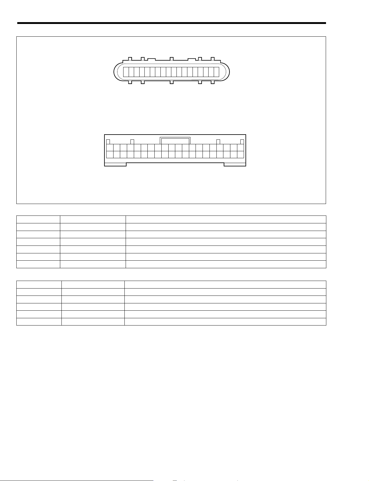
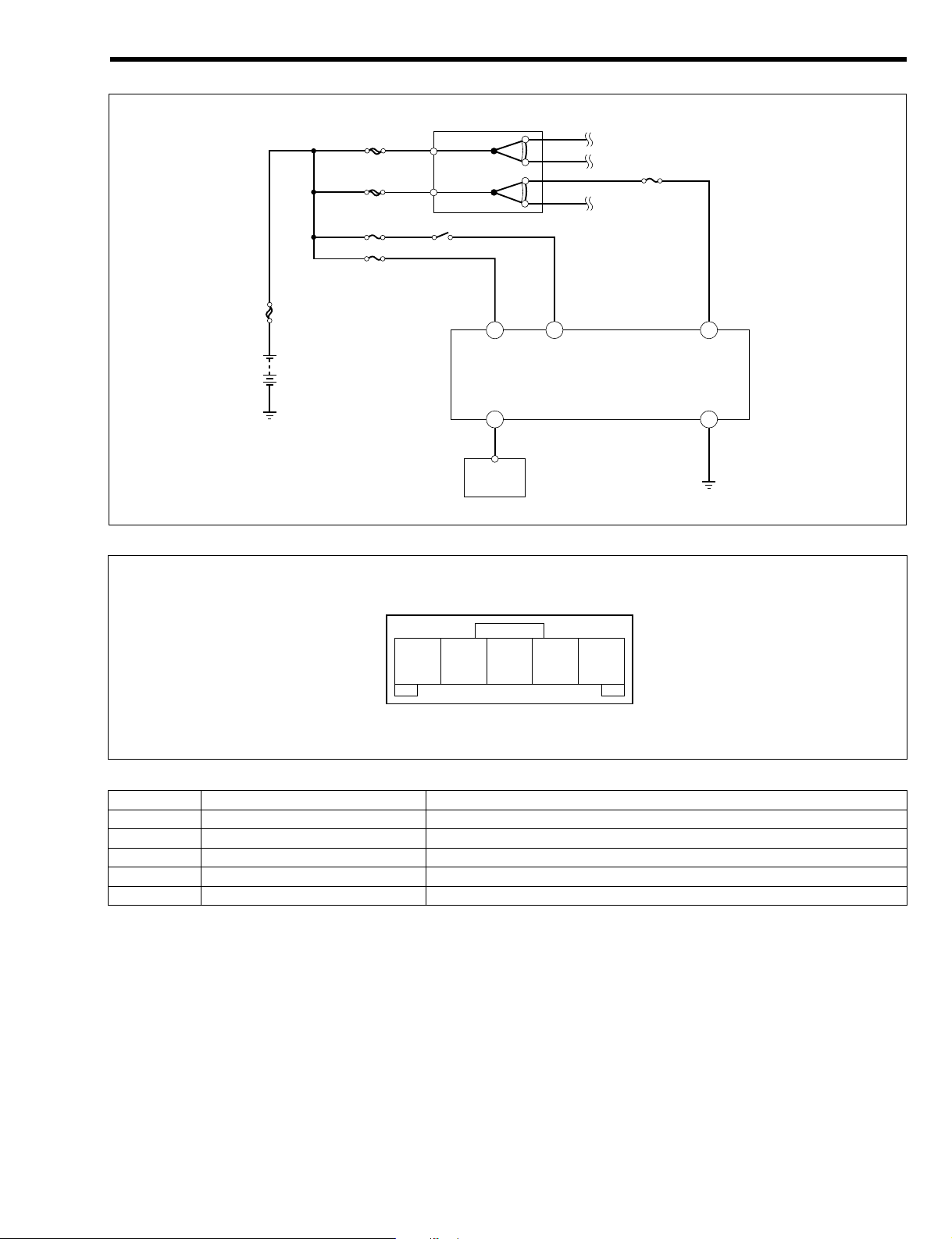
3COMPONENTS
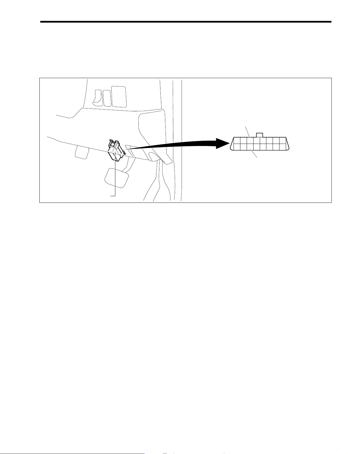
3-1 DLC
A DLC (Data Link Connector) is installed forward of the driver's seat (lower portion of the instrument panel,
driver's seat door side).
CANH and CANL terminals have been added to the DLC with the adoption of a CAN communication system.
3-2 TERMINATING RESISTANCE
The terminating resistance is located in the combination meter and in the engine control computer.
As the terminating resistance, there are two 60 + resistors in series. As a result, the differential voltage
can be judged from the loop connected network.
T11E1206S16
DLC
12345678
9 10 11 12 13 14 15 16
CANL
CANH
L2–12
Page 16
ÄÄ
LIN COMMUNICATION SYSTEM
1OUTLINE
1-1 DESCRIPTION
1.All vehicles are equipped with LIN communication (LIN: Local Interconnect Network) *.
2.The LIN communication consists of the meter ECU and ITC.
3.Multiplex communication is a system in which plural ECU's are connected to a single communication
line to provide mutual data exchange. This has made it possible to integrate the system and prevent
the number of wires from increasing when a function is added.
4.Controls actually taking place in the multiplex communications are the wake-up/sleep controls, system
controls by applicable ECU and so forth.
5.A diagnosis function is provided that will inform the operator of any abnormality of the system. Also,
fail-safe functions are provided that will assure the minimum functions for each ECU and protect the
systems when abnormal communications occur between the ECUs.
6.The communication method employs a single master system in which the meter ECU controls the sleep
(low current mode), wake-up (standby mode), etc. of the communication applicable ECU.
NOTE
• *: The LIN communication is a multiplex communication network mainly intended for the data communications between the body-related control ECUs.
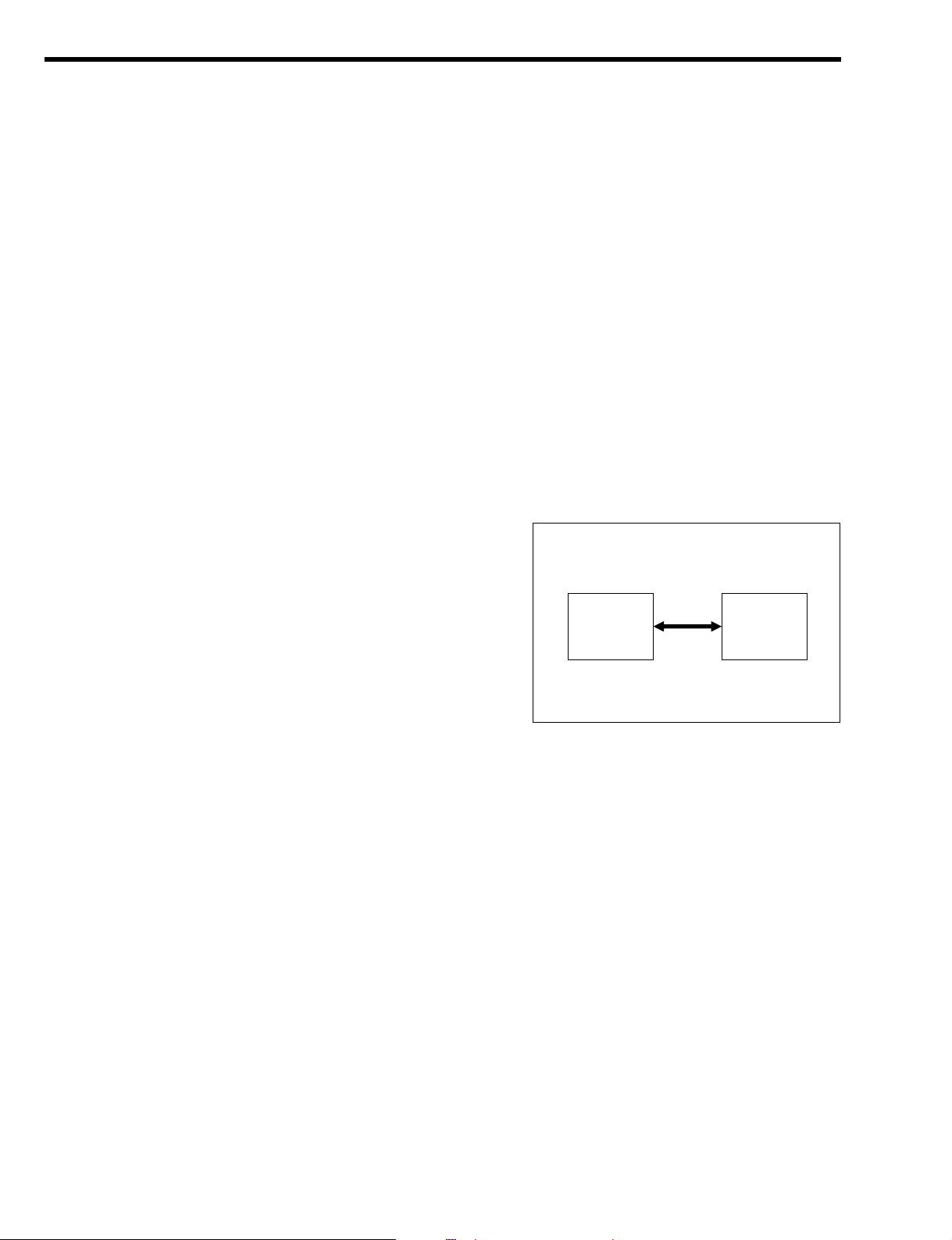
1-2 SYSTEM DRAWING
The LIN communication consists of the meter ECU and ITC.
L2–13
B11H1022ET10
Meter ECU ITC
Page 17
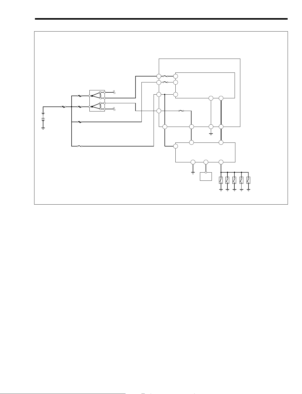
1-3 SYSTEM WIRING DIAGRAM
T11H1539ES25
DLC
9
ECUB
ECU IG2
17
BDR1
7
IG1
'B
ITC
MPX
6
GND
1
LIN communication
wire
AM1
AM2
IG1
IG1/BACK
D/LOCK
BACK UP
F/L
IG SW
ST
ACC
IG1
IG2
Fuse block
10
IG2
9
LIN
20
Combination meter
GND
18
ECU-T17DOOR
11
Courtesy switch
Front left
Front right
Rear right
Rear left
BACK
L2–14
Page 18
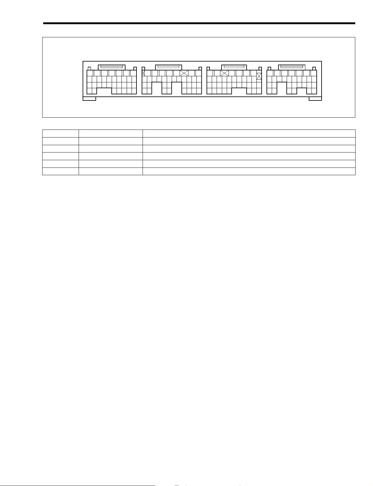
Arrangement of ECU terminal
Meter terminal name (Multiplex communication system)
ITC terminal name (Multiplex communication system)
Terminal No. Terminal code Terminal name
1 GND Earth
6 MPX Multiple communication input/output
7 IG1 ECU power supply
9 ECU B ECU power supply
17 BDR1 Power supply
Terminal No. Terminal code Terminal name
9 IG2 IG power supply
10 +B 'B power supply
11 DOOR Input of courtesy switch signal
17 ECU-T ECU-T terminal signal input
18 GND Earth
20 LIN LIN communication input/output
T11H9502ES20
ITC
Combination meter
1 2 3 4 5 6 7 8 9 10 11 12 13 14 15 16 17 18
30 29 28 27 26 25 24 23 22 21
10 9 8 7 6 5 4 3 2 1
40 39 38 37 36 35 34 33 32 31
20 19 18 17 16 15 14 13 12 11
L2–15
Page 19
1-4 LOCATION OF COMPONENTS
The illustration represents the RHD vehicle. In the case of the LHD vehicle, the combination meter is located at the left side.
a Meter ECU (inside the combination meter)
b ITC
c Front door courtesy switch
d Rear door courtesy switch
e Back door courtesy switch (inside the back door lock Ay)
T11H1525S25
a
e
c
b
d
d
c
L2–16
Page 20

2CONTROL
2-1 COMMUNICATION CONTROL
2-1-1 DESCRIPTION
The meter ECU controls the following items.
1.Evaluation of presence/non-presence of ECU
2.Communication start informing control
3.Wake-up/sleep control
2-1-2 EVALUATION OF PRESENCE/NON-PRESENCE OF ECU
The meter ECU detects the presence of the ECU every time the battery power supply is turned on.
1.When the LIN communication applicable ECU is not connected to the meter ECU, or when it does not
respond to the meter ECU due to failure, etc. of the LIN communication applicable ECU, the meter
ECU transmits a command to other ECUs that have been judged to be present to perform such communication control that is to be carried out when the ECU that has made no response is not mounted
(Evaluation of ECU non-presence).
2.The meter ECU, after detecting the presence of the ECU, continues to monitor ECU connecting status
at constant intervals.
3.When the LIN communication applicable ECU responds properly to the meter ECU during the ECU
presence/non-presence evaluation, or when the ECU that has made no response returns to the normal condition and makes a proper response after the ECU has been judged not to be present, the
meter ECU transmits a command to other LIN communication applicable ECUs to perform such communication control that is to be carried out when the ECU that has made a response is mounted
(Evaluation of ECU presence).
2-1-3 COMMUNICATION START CONTROL
The communication start is always started from the meter ECU. The signal of communication start is transmitted to other ECU.
2-1-4 WAKE-UP/SLEEP CONTROL
When transferring to the sleep (the low current mode), or transferring from the sleep (the low current
mode) to the wake-up (the standby mode), the meter ECU transmits a transfer start command to the other
LIN communication applicable ECUs, thereby transferring to the wake-up/sleep control.
2-2 WAKE-UP/SLEEP FUNCTION
2-2-1 DESCRIPTION
The LIN communication system is equipped with a wake-up/sleep function to reduce the current used
when the IG switch is in the ACC and LOCK positions.
2-2-2 CONDITIONS FOR REALIZING SLEEP
When the following conditions 1 and 2, or the condition 3 is satisfied, the meter ECU sends a sleep command to each ECU, thus transferring to the sleep state (the low current mode).
1.The IG switch is set to the ACC position or the LOCK position.
2.The meter ECU received the information that the control of each ECU is complete, and the control of
the meter itself is complete.
3.Ten minutes have passed after the IG switch was set to the ACC position or the LOCK position, with
the door open (the battery discharging prevention function).
2-2-3 CONDITIONS FOR REALIZING WAKE-UP
When either of the following conditions is satisfied, the meter ECU sends a wake-up command to each
ECU, thus transferring to the wake-up state (the standby mode).
1.Cases where there is a change in the data to be communicated at each ECU, and the ECU transmits
a wake-up (the standby mode) signal to the meter ECU.
2.Cases where the IG switch is turned from the ACC or LOCK position to the ON position.
3.Immediately after connecting a battery.
L2–17
Page 21

2-3 LIN COMMUNICATION PROTOCOL (COMMUNICATION REGULATION)
1.The LIN communication system is a two-way interactive time-division multiplexing communication system, where all ECUs that make up the network can send and receive data by delaying the timing for
using a communication line in order to share a single communication line. Each ECU, therefore, communicates according to the common communication protocol (communication regulation) to ensure
smooth and reliable communication.
2.The data used by the LIN communication system consist of digital signals that include information such
as ID to identify each ECU (node ID) and contents of communication data.
3.In order for all ECUs to be able to communicate by sharing a single communication line, based on the
specified transmission time schedule, the single master system is employed as a communication regulation for the communication line, in which the meter ECU controls the communication timing, sleep
(the low current mode) and wake-up (the standby mode), etc. of the communication applicable ECU.
2-4 DIAGNOSIS (ONBOARD DIAGNOSIS FUNCTION)
This is a function whereby the ECU informs the inspection operator of the abnormal items when there has
been a failure in the system. When failure takes place, the ECU memorizes the abnormal item.
Please refer to the repair manual for details concerning the diagnosis.
2-5 FAIL-SAFE FUNCTION
When communication remains unestablished between the applicable ECU and the meter ECU for a certain length of time, the predetermined control is performed by transferring to the fail-safe mode.
Conditions of each system during the fail-safe mode
CAUTION
• When the meter ECU transfers to the fail-safe mode, the ITC, being unable to communicate with
the meter ECU, will transfer to the fail-safe mode.
Applicable ECU Condition
ITC
;The keyless operation will not take place.
;The room lamp control will not take place.
*: The power door locking operates normally.
L2–18
TO INDEX TO NEXT SECTION
Page 22

HEATER AND AIR CONDITIONER----------- K1 - 1
OUTLINE ----------------------------------------- K1 - 1
CONSTRUCTION AND OPERATION ---- K1 - 4
REFRIGERANT------------------------------ K1 - 4
DISCHARGE PORT ------------------------ K1 - 4
CONTROL PANEL-------------------------- K1 - 5
HEATER CORE------------------------------ K1 - 5
EVAPORATOR------------------------------- K1 - 6
COMPRESSOR ----------------------------- K1 - 6
CONDENSER -------------------------------- K1 - 6
MANUAL AIR CONDITIONER SYSTEM ---- K1 - 7
OUTLINE ----------------------------------------- K1 - 7
SYSTEM WIRING DIAGRAM ------------ K1 - 7
LOCATION OF COMPONENTS--------- K1 - 9
LOCATION OF COMPONENTS ------- K1 - 11
CONTROL-------------------------------------- K1 - 13
AIR CONDITIONER CONTROL BY
ENGINE CONTROL COMPUTER ---- K1 - 13
COMPONENTS------------------------------- K1 - 14
ENGINE CONTROL COMPUTER ---- K1 - 14
BLOWER RESISTOR -------------------- K1 - 14
PRESSURE SWITCH -------------------- K1 - 14
EVAPORATOR TEMPERATURE
SENSOR------------------------------------- K1 - 15
CONTROL PANEL ------------------------ K1 - 15
K1 HEATER & AIR CONDITIONER
K1
TO INDEX
Page 23

ÄÄ
HEATER AND AIR CONDITIONER
1OUTLINE
1.Some specifications have an air conditioner with manual controls.
2.A Three-dial control panel has been set.
3.The evaporator employs a small, lightweight type RS Evaporator (RS: Revolutionary Super Slim) which
improves the evaporator's heat exchange efficiency when the air conditioner is running.
4.The heater core employs a small, lightweight SFA heater core @ (SFA: straight flow aluminum) which
should give superior heat transmission performance when the system is heating.
5.The refrigerant HFC-134a (R-134a) that contains no chlorine has been adopted as the air conditioner
refrigerant, taking into consideration the need to prevent ozone layer depletion.
K1–1
Page 24
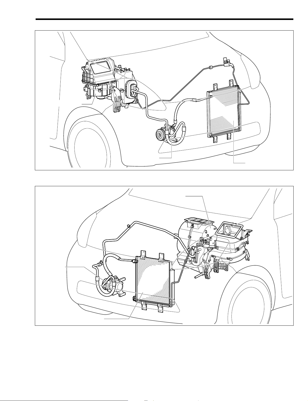
Front section (LHD vehicle)
The illustration shows a typical example.
Front section (RHD vehicle)
The illustration shows a typical example.
T11H1023ES20
Compressor
Air conditioner unit
Condenser
T11H1514ES20
Cooling unit
Compressor
Condenser
K1–2
Page 25
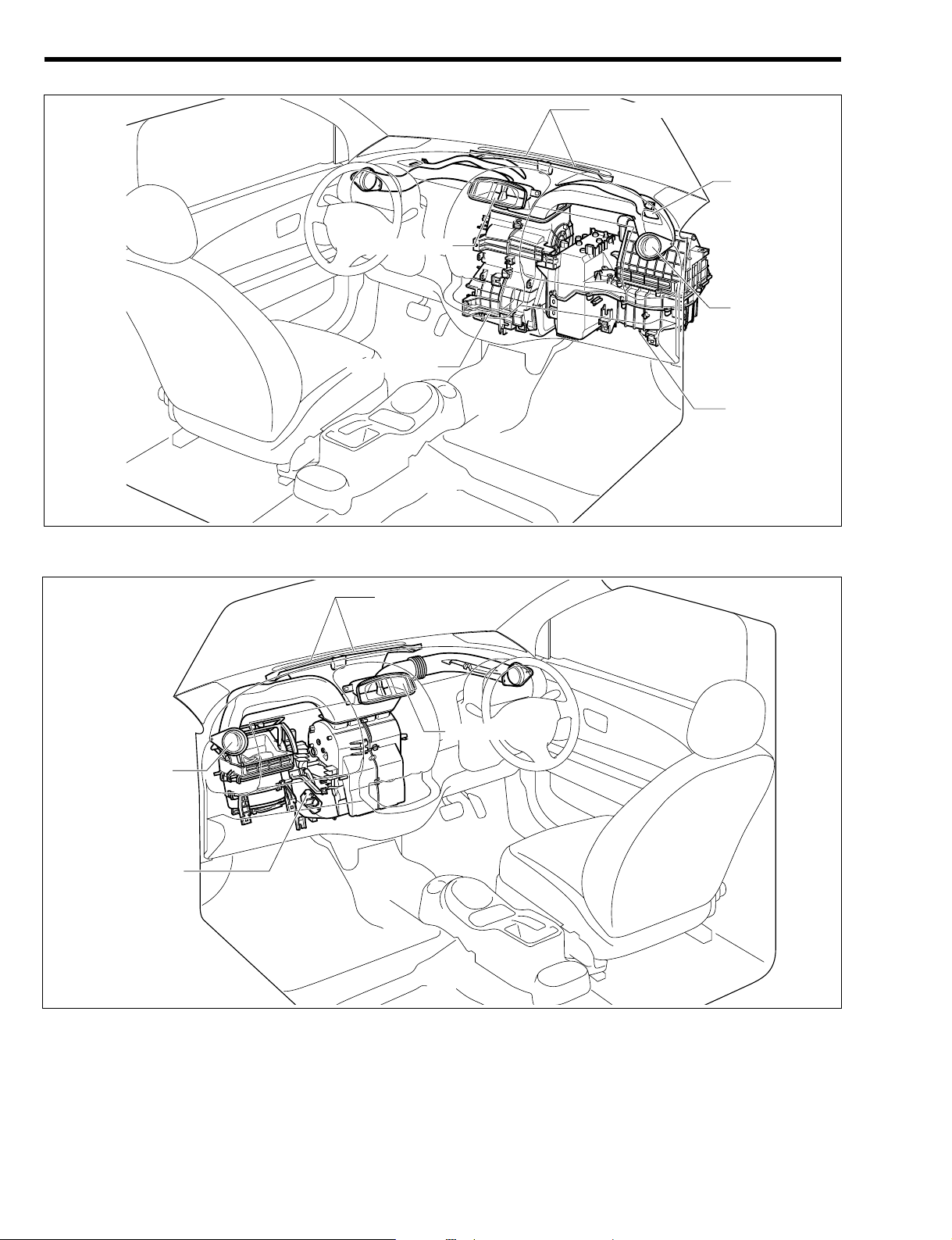
Instrument panel section (LHD vehicle)
The illustration shows a typical example.
Instrument panel section (RHD vehicle)
The illustration shows a typical example.
T11H1516ES20
Front defroster
Side register
Center register
Air conditioner unit
T11H1515ES20
Cooling unit
Heater unit
Side register
Center register
Side defroster
Front defroster
K1–3
Page 26
2CONSTRUCTION AND OPERATION
2-1 REFRIGERANT
The refrigerant HFC-134a (R-134a) that contains no chlorine has been adopted as the air conditioner
refrigerant, taking into consideration the prevention of deletion of ozone layer.
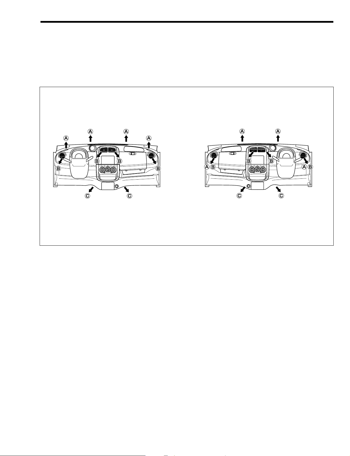
2-2 DISCHARGE PORT
The air outlets are located in the center of the instrument panel, on both side-sections, on the defroster
and on the leg sections of people sitting in front seats.
Air outlets according to mode
T11H1517ES20
LHD vehicle RHD vehicle
K1–4
Page 27
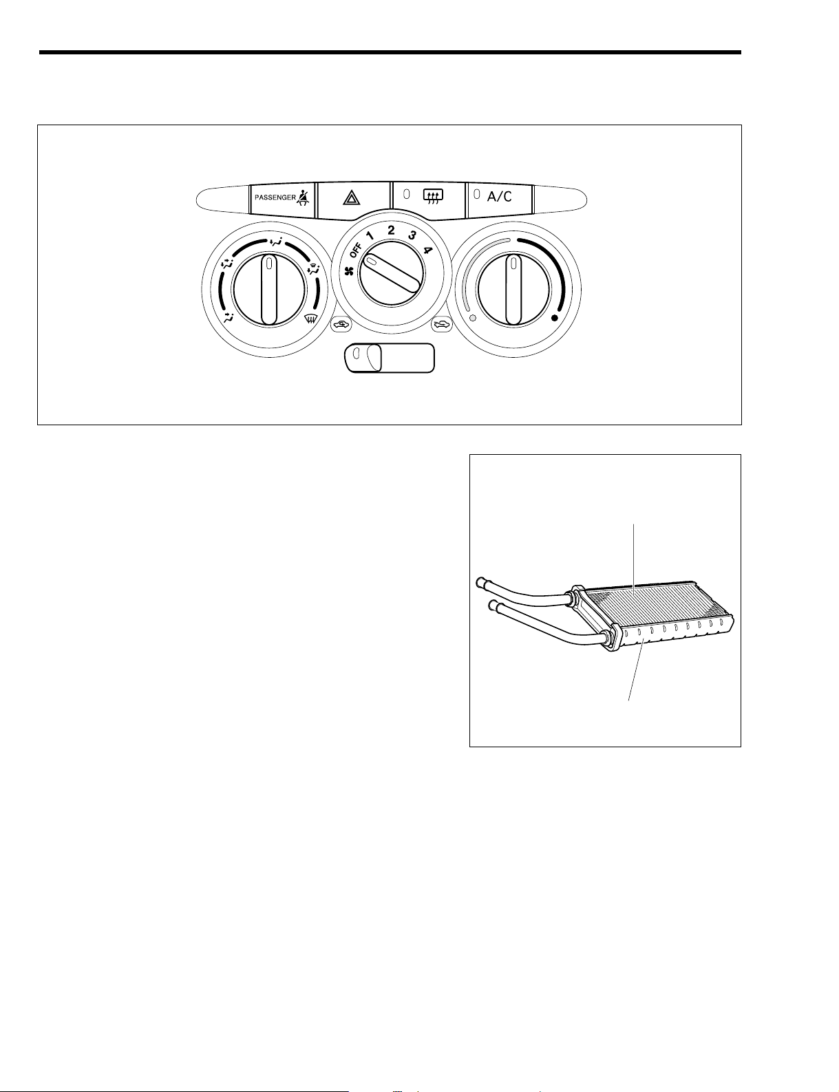
2-3 CONTROL PANEL
A three-dial type control panel is employed. The dial pointer adopts night illumination to assure easy operation and reading night time. The blower switch can be adjusted over four stages.
The illustration shows a typical example.
2-4 HEATER CORE
The heater core employs a small, lightweight SFA heater core
@ (SFA: straight flow aluminum).
The SFA heater core @ is more compact than conventional
SFA heater cores because of the reduction in tank width and
height/miniaturization of the core (core area expansion). This
has achieved increased air flow, noise reduction, and an
improvement in heating capacity. The SFA heater core @ is
constructed from tubes, fins and capsules and the result has
been that by flattening the tubes the heat transfer rate has
been improved as well as producing a lightweight, small size
heater. Further, the use of aluminum makes the heater more
environmentally friendly.
T11H1054S16
K1–5
T11H1055ET16
TubeQfin
Capsule
Page 28
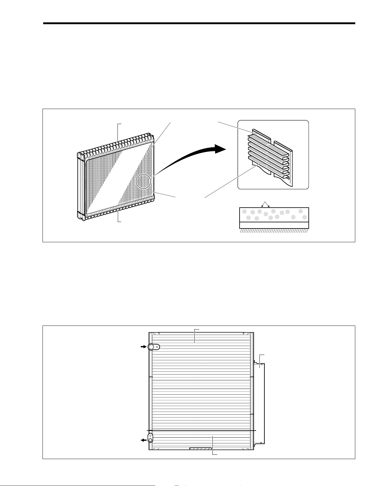
2-5 EVAPORATOR
The evaporator employs a small, lightweight type RS Evaporator (RS: Revolutionary Super Slim).
The RS evaporator consists of a tank, tubes and cooling fins. Thanks to the press molding of the tube,
minute flow paths have been formed and this leads to improved heat transfer capability and very thin
dimensions. Further, the RS evaporator has improved heat transfer due to the reduced fin height, tube
thickness, and fin pitch, and the unit is much reduced in size and weight due to the reduced stock thickness of the core material. The evaporator is coated with a hydrophilic plastic film which contains anti-bacteria agent to control the breeding of germs and bacteria which can lead to unpleasant smells. In consideration of the environment the surface treatment is chrome-free.
2-6 COMPRESSOR
Vane type compressor is employed.
2-7 CONDENSER
A new type of sub cooling condenser is used which has improved performance with its miniaturized core
and an increased effective surface area, compared with the conventional ones. Inside the sub cooling
condenser are provided the condensing section, the modulator and the over cooling section (sub cooling
section). The refrigerant vapor goes through a 2-stage condensation process which lead to nearly 100%
liquidizing.
Further, the modulator separates the gas and liquid.
The illustration shows a typical example.
T11H1057ES16
Modulator
Condensing section
Super cooling section (sub-cooling section)
IN
Evaporated refrigerant
OUT
Liquid refrigerant
T11H1056ES16
Tank
Tank
Cooling fin
Fine multi-hole tube
Anti-bacteria agent is added to hydrophilic
resin coating
Hydrophilic resin coating
Chrome-free chemical conversion coating
Aluminum base metal
K1–6
Page 29
ÄÄ
MANUAL AIR CONDITIONER SYSTEM
1OUTLINE
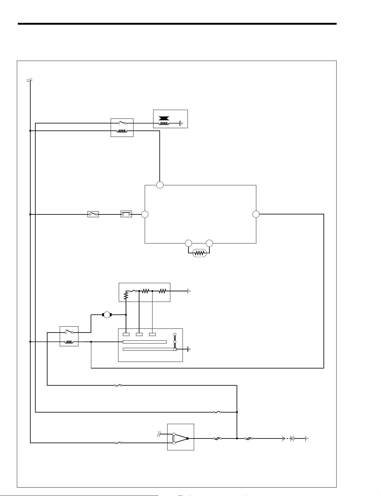
1-1 SYSTEM WIRING DIAGRAM
T11H8501ES48
IG1
/BACK
AM1
HEATER
Heater
relay
Hi
M2
M1
Lo
F/L
MGC
IG
SW
IG1 ACC
A/C
SW
Pressure switch
Magnetic clutch relay
Compressor
magnet clutch
Blower switch
Blower resistor
M
Blower motor
ACSW
MGC
3
BLW
42
ACEV45E21
116
Evaporator
temperature
sensor
Engine control computer
36
K1–7
Page 30
Arrangement of ECU terminal
Engine Control Computer terminal name
Terminal No. Terminal code Terminal name
3 ACSW A/C switch input
36 MGC Magnet clutch drive output
42 BLW Heater blower operation input
45 ACEV Evaporator temperature sensor input
116 E21 Sensor earth
H11E6091S10
1
28293031323334353637
7071727374757677
107108109110111112
23
4
56721
60616263646566676869
979899
100101102105106
129
130133134135
222324252627
103104
131
132
383940414243444546
7879808182838687
113114118119
8910111213
8485
115116117
47
88
120
495051525354555657
89909192
121122
141516171819
48
9394
123124125126
58
95
127
59
96
128
20
K1–8
Page 31

1-2 LOCATION OF COMPONENTS
a Pressure switch
b Compressor magnet clutch
c Blower switch
d A/C switch
e Engine control computer
T11H1519S33
b
c
d
e
a
K1–9
Page 32

K1–10
h
f Blower motor
g Blower resistor
h Evaporator temperature sensor
g
f
T11H1520S25
Page 33

1-3 LOCATION OF COMPONENTS
a Pressure switch
b Compressor magnet clutch
c Blower switch
d A/C switch
e Engine control computer
T11H1521S33
b
c
d
e
a
K1–11
Page 34

K1–12
f
f Blower motor
g Blower resistor
h Evaporator temperature sensor
h
g
T11H1522S25
Page 35

2CONTROL
2-1 AIR CONDITIONER CONTROL BY ENGINE CONTROL COMPUTER
2-1-1 AIR CONDITIONER CUT CONTROL
Type 1 KR-FE eng ine mo unt ed veh icl es
Refer to Page B8-16.
Type K 3-VE en gin e mo unt ed veh icl es
Refer to Page B8-44.
2-1-2 RADIATOR FAN MOTOR CONTROL
Type 1 KR-FE eng ine mo unt ed veh icl es
Refer to Page B8-17.
Type K 3-VE en gin e mo unt ed veh icl es
Refer to Page B8-45.
2-1-3 AIR CONDITIONER IDLE-UP CONTROL
Type 1 KR-FE eng ine mo unt ed veh icl es
Refer to Page B8-17.
Type K 3-VE en gin e mo unt ed veh icl es
Refer to Page B8-45.
2-1-4 MAGNETIC CLUTCH CONTROL
Type 1 KR-FE eng ine mo unt ed veh icl es
Refer to Page B8-17.
Type K 3-VE en gin e mo unt ed veh icl es
Refer to Page B8-45.
K1–13
Page 36

3COMPONENTS
3-1 ENGINE CONTROL COMPUTER
This is attached below the air conditioning unit. It controls the
compressor magnetic clutch ON/OFF function depending on
the state of the A/C switch, vehicle conditions and each sensor's input.
3-2 BLOWER RESISTOR
The blower resistor controls the speed of the blower motor. A
temperature fuse is fitted. The mounting location is on the air
conditioning unit.
3-3 PRESSURE SWITCH
A pressure switch, which corresponds to abnormal pressure variation inside the liquid tube, is provided
inside the liquid tube. When the pressure inside the liquid tube becomes excessively high or low, the wire
between the A/C switch and the engine control computer is interrupted, thus stopping the rotation of the
compressor.
L21H1504ES16
OFF
[kPa]
{kgf/cm }
ON
196
{2.0}
225
{2.3}
2550
{26}
3140
{32}
2
Pressure switch
K1–14
T11E1026T10
C11H1032ET10
Hi M2 M1 Lo
Temperature fuse
Page 37

3-4 EVAPORATOR TEMPERATURE SENSOR
This sensor detects the air temperature at a point immediately downstream of the evaporator as a change in resistance.
Thus, the outputted value is sent to the engine control computer.
3-5 CONTROL PANEL
Refer to Page K1-5.
K1–15
T11H1523ET16
Evaporator temperature
sensor
T11H1062ET16
Evaporator
temperature
sensor
TO INDEX TO NEXT SECTION
Page 38

CONSTRUCTION AND OPERATION----- J6 - 1
HORN------------------------------------------- J6 - 1
REAR WINDOW DEFOGGER ----------- J6 - 1
POWER OUTLET---------------------------- J6 - 1
CIGARETTE LIGHTER--------------------- J6 - 2
J6 OTHER ELECTRICAL PARTS
J6
TO INDEX
Page 39

1CONSTRUCTION AND OPERATION
1-1 HORN
The horn has employed the flat type high-pitch horn which
features a compact design and light weight.
Specification table
1-2 REAR WINDOW DEFOGGER
1.The rear window defogger is provided on all models.
2.The switch is provided inside the air conditioner control
panel.
3.When the switch is turned ON, the operation indicating
lamp provided at the switch illuminates.
Specification table
1-3 POWER OUTLET
1.The power outlet which can provide power to DC12V electric appliances is provided according to the specifications.
2.The installing location is at the central/lower section of the
instrument panel.
Specification table
Rated voltage (V) 12
Maximum power capacity (W) 120
Maximum current (A) 10
Number of wires 12
Rated voltage (V) 12
Consumption power (W) 93
Rated voltage (V) 12
Operating current (A) 3.0&1
Sound pressure level (dB) 113
Basic frequency (Hz) 420
J6–1
T11H1051T10
T11H1535T10
T11H1540T16
Page 40

1-4 CIGARETTE LIGHTER
1.The cigarette lighter is provided according to the specifications.
2.The cigarette lighter body is provided with a temperature
fuse. This fuse is melt down if current continues to flow to
the cigarette lighter due to abnormality.
Specifications table
Rated voltage (V) 12
Maximum current (A) less than 10
Temperature fuse melt time (sec) 90 - 145
J6–2
C11H1015ET16
Temperature fuse
TO INDEX TO NEXT SECTION
Page 41

CONSTRUCTION AND OPERATION----- J5 - 1
FUSIBLE LINK-------------------------------- J5 - 1
BATTERY -------------------------------------- J5 - 1
SIDE JUNCTION BLOCK ----------------- J5 - 1
FUSE BLOCK--------------------------------- J5 - 2
RELAY BLOCK------------------------------- J5 - 2
J5 WIRING
J5
TO INDEX
Page 42

1CONSTRUCTION AND OPERATION
1-1 FUSIBLE LINK
The wire type fusible link is provided at the side of the battery.
1-2 BATTERY
1.Two kinds of the batteries shown below have been provided.
2.The battery is provided at the left side of the engine compartment.
Specification table
1-3 SIDE JUNCTION BLOCK
1.The side junction block integrates junction connectors that
internally connect the wirings.
2.Use of the side junction block has made it possible to
reduce the number of the junction connectors, thus simplifying wirings.
3.The side junction block is located at the foot area of the
front left seat at the vehicle outer side.
Standard vehicle 40B19L
Cold region specification vehicle 44B20L
J5–1
T11H1048ET16
Fusible link
T11H1049T16
Page 43

1-4 FUSE BLOCK
The fuse block is located at the left side of the instrument panel.
1-5 RELAY BLOCK
The relay block is located at the rear of the battery.
T11H1533S20
IG
50A
7.5A
10A
10A
15A
7.5A
10A
10A
20A
BACK UP
TAIL
(DOME)
(ABS2)
(ECU-B)
10A
10A
10A
10A
(A/C)
(H-LP HI LH)
(H-LP HI RH)
(FOG LH)
(FOG RH)
H-LP LH
/H-LP LO LH
H-LP RH
/H-LP LO RH
(EPS)
50A
(ABS1)
40A
AM1
50A
AM2
30A
RAD
30A
(POWER)
30A
HEATER
40A
HEATER
RAD
HEAD
(MGC)
EFI
HORN
(MGC)
STOP
15A
15A
10A
10A
(FOG)
T11H1532ES25
7.5A
15A
ST
10A
D/LOCK
HAZ
7.5A
ENGINE
10A 20A
ECU IG2
7.5A
DEFOG
20A 7.5A
IG1/BACK
WIPER
POWER
7.5A
ECU IG1
15A
ACC
CIG
30A
Starter relay
Flasher relay
IG relay
EFI main relay
Horn relay
Fuel pump relay
RHD vehicle
LHD vehicle
J5–2
TO INDEX TO NEXT SECTION
Page 44

CONSTRUCTION AND OPERATION----- J4 - 1
AUDIO SYSTEM ----------------------------- J4 - 1
J4 AUDIO & VISUAL SYSTEM
J4
TO INDEX
Page 45

1CONSTRUCTION AND OPERATION
1-1 AUDIO SYSTEM
1-1-1 DESCRIPTION
1.As for the speakers, 10cm front speakers or 10cm front speakers & 16 cm rear speakers are available
according to the specifications.
2.As for the radio antenna, roof antennas have been employed for all models.
The illustration represents a typical example.
T11H1530ES33
Rear speaker
Rear speaker
Front speaker
Front speaker
Tuner
Roof antenna
J4–1
Page 46

1-1-2 TUNER
1.An AM/FM radio with compact disc player employing a surface design which has a single surface with
the center cluster is available in some specifications. The AM/FM radio with compact disc player has
only buttons that are needed indispensably. For improved operation and easy reading, large indicating letters are employed.
2.For improved operation and easy reading, the mounting position has been set to the upper part of the
instrument panel.
1-1-3 SPEAKER
1.As for the speakers, 10cm front speakers or 10cm front speakers & 16 cm rear speakers are available according to the specifications.
2.The front speakers have been set on either side at the upper side of the instrument panel.
3.The rear speakers have been set on the bottom section of the door panels on either side.
Specification table
Applicable place Front Rear
Size (cm) 10 16
Rated input (W) 12 15
Momentary maximum input (W) 35 35
Impedance (+) 6&0.9 4&0.6
Output sound pressure level 85&3 85.5&3
Minimum resonance frequency (Hz) 95&19 90&18
1 2 3
Power supply switch / volume and mode control knob
Mute button
Sound button
Mode button
AM button / AM auto store button
FM button / FM auto store button
Tuning button / track button
Preset station selection button1
Preset station selection button2
Preset station selection button3
Preset station selection button4 / scan button
Preset station selection button5 / repeat button
Preset station selection button6 / random button
AF (alternative frequency) button
PTY (Program type) button
TA (traffic announcement) button
Compact disc insertion slot
Play / pause button
Eject button
q
w
e
r
t
y
u
i
o
!0
!1
!2
!3
!4
!5
!6
!7
!8
!9
Preset station selection indicator
Radio mode indicator
Disc indicator
Compact disc mode indicator
Sound mode indicator
Display section
<Display section>
T11H1531S20
J4–2
Page 47

1-1-4 RADIO ANTENNA
A roof antenna has been employed. As for this antenna, it is
movable (in 180 degrees) in the backward and forward direction and its pole is detachable. Installation and removal may
be done by turning the pole of the antenna.
J4–3
A11H1015ET1
Installation
Removal
TO INDEX TO NEXT SECTION
Page 48

OUTLINE------------------------------------------ J3 - 1
DESCRIPTION ------------------------------- J3 - 1
SYSTEM WIRING DIAGRAM ------------ J3 - 3
CONSTRUCTION AND OPERATION----- J3 - 7
SPEEDOMETER----------------------------- J3 - 7
TACHOM ETE R ----- --- -------- -------- ------- J3 - 9
ODOMETER TRIP METER --------------- J3 - 9
FUEL GAUGE------------------------------- J3 - 10
WARNING / INDICATOR ----------------- J3 - 11
WARNING BUZZER----------------------- J3 - 16
CLOCK---------------------------------------- J3 - 16
WATER TEMPERATURE
INDICATION FUNCTION ---------------- J3 - 17
CAN COMMUNICATION----------------- J3 - 18
LIN COMMUNICATION------------------- J3 - 18
DIAGNOSIS (ONBOARD
DIAGNOSIS FUNCTION) ---------------- J3 - 19
FAIL-SAFE FUNCTION------------------- J3 - 19
J3 METER
J3
TO INDEX
Page 49
1OUTLINE
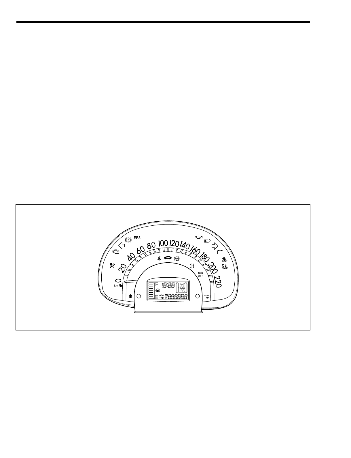
1-1 DESCRIPTION
1.The designing and legibility have been enhanced by positioning the meter on the upper part of the
steering column.
2.Legibility and visibility have been enhanced by employing the letter size which provides comprehensibility and easy reading.
3.As for the odometer ; trip meter, electric type odometer ; trip meter equipped with a twin trip meter
has been employed.
4.A tachometer is available on some Specifications. The tachometer is separate from the combination
meter and is positioned on the upper part of the instrument panel.
5.For some of the communications of the meter and other ECU, multiplex communication of CAN
(Controller Area Network) and LIN (Local Interconnect Network) has been employed.
6.A clock is set within the meter.
7.An excellent visibility is achieved by indicating fuel gauge, odometer ; trip meter, shift position indicator and clock in LCD (Liquid Crystal Display).
8.A multi-buzzer that makes a buzzer sound while various warnings are given such as when the key is
remaining in the key cylinder, or when reversing has been employed and is built in the meter.
9.Fuel level warning function has been employed for all models.
10.Power saving and long lasting features have been promoted by employing LED for all lightings such
as the dial plate and the indicator lamps.
Combination meter
The illustration represents a major example.
T11H1526S16
J3–1
Page 50

Ta ch o me t er
T11H1031S16
J3–2
Page 51

1-2 SYSTEM WIRING DIAGRAM
1-2-1 COMBINATION METER
T11H6501ES48
IG SW
AM2
TAIL
BACK UP
F/L
HORN
Key switch
Parking brake switch
ST
ACC
AM1
IG1
IG2
ECU IG2
Tail SW
SPEED
Immobilizar
ECU
LCD
ITC
Fuel sender gauge
Buzzer
High-water
temperature
Courtesy
switch
Door
10
32
26
2
KSW
DLC
bac
d
Low-water
temperature
ABS
O/D OFF
Brake
Driver's seat belt
9 14
1 3 4
ECU-T
17
MPX
20
Keyless
receiver
21
SIG
11
Brake fluid level switch
M/TandABS
non-equipped
vehicle
Vehicle
speed sensor
Driver's seat belt switch
Passenger's seat belt warning
lamp
Passenger's seat
belt switch
Occupant
detectiion
sensor
8 39
EPS ECU
To EFI ECU
A/T ECU
ABS ECU
(CAN
communication)
To DLC
(CAN
communication)
RHD vehicles
SPD
12
Meter ECU
Seat belt warning
lamp flashing
control circuit
22 1821 3 4
To A/T ECU
ABS ECU
(CAN
communication)
To EFI ECU
DLC
(CAN
communication)
LHD vehicles
7
23 31
J3–3
Page 52

J3–4
To headlamp circuit
To rear fog switch
IND
Immobilizer
ECU
To flasher relay
High beam
Dimmer passing switch
Meter illumination
Rear fog
Security
Turn R
28 29 27 16 13 5
Turn L
bac
MIL
Oil
Charge
EPS
Air bag
LA
A/B ECU
W
EFI ECU
Oil pressure switch
Alternator
15 24 25 30 33 6
d
EPSW
EPS ECU
T11H6502ES48
Page 53

Arrangement of meter terminal
Meter terminal name
Terminal
No.
Terminal code Terminal name
1 CANH CAN communication HI (1)
2 CANL CAN communication LO (1)
3 HCAN CAN communication HI (2)
4 LCAN CAN communication LO (2)
5 BEAM+ High beam '
6 BEAM( High beam (
7 SPD Input of vehicle speed signal
8 BRK Input of brake fluid signal
9 IG2 IG power supply
10 +B 'B power supply
11 DOOR Input of courtesy switch signal
12 SPOUT Output of vehicle speed signal
13 TAIL Illumination +
14 PKBSW Parking brake
15 EPS EPS
16 RR-FOG Rear fog lamp
17 ECU-T ECU-T terminal signal input
18 GND Earth
19 ((
20 LIN LIN communication input/output
21 FUEL Input of fuel signal
22 D-BELT Seat belt at driver's seat side
23 P-BELT Front passenger seat side seat belt signal input
24 CHG Charge
25 OIL Oil
26 KEY2 Output of key switch signal
27 SEC Security
28 TURNL Turn LH
29 TURNR Turn RH
30 MIL MIL
31 P-BELOUT Front passenger seat side seat belt signal output
32 KEY Input of key switch signal
33 A/B Airbag
34 ((
35 ((
36 ((
37 ((
38 ((
39 KLS Keyless receiver signal input
40 ((
T11H6013S10
30 29 28 27 26 25 24 23 22 21
10 9 8 7 6 5 4 3 2 1
40 39 38 37 36 35 34 33 32 31
20 19 18 17 16 15 14 13 12 11
J3–5
Page 54
1-2-2 TACHOMETER
Arrangement of tachometer terminal
Ta ch o me t er termi n al name
Terminal No. Terminal code Terminal name
1 ILL Illumination
2 REV Input of engine revolution speed signal
3 IG IG power supply
4 'B 'B power supply
5 GND Earth
T11H6017S10
54321
T11H6016ES20
IG SW
AM2
TAIL
BACK UP
F/L
ST
ACC
AM1
IG1
IG2
ECU IG2
Tail SW
Tachometer
EFI ECU
REV
+B ILL
IG
REV GND
1
4
2
3
5
J3–6
Page 55

2CONSTRUCTION AND OPERATION
2-1 SPEEDOMETER
2-1-1 DESCRIPTION
1.For the speedometers, the electric type has been employed for all models.
2-1-2 SPECIFICATIONS
2-1-3 VEHICLE SPEED SENSOR (MRE TYPE)
(1) Description
1.A MRE type (MRE: Magnetic Resistance Element) vehicle
speed sensor has been set in the ABS non-installed M/T
vehicle as the vehicle speed signal detection sensor.
2.The vehicle speed sensor is installed to the transaxle.
3.The vehicle speed is detected by the rotating gear of the
vehicle speed sensor.
Indication Function
Indication range:
0 - 220 km/h
0 - 140 MPH
At increments of 10 km/h
At increments of 10 MPH
Electric type (pointer: stepper motor type)
Vehicle speed signal source:
ABS ECU [ABS-equipped vehicles]
A/T ECU [A/T vehicles without ABS]
Vehicle speed sensor (MRE type) [M/T vehicles without ABS]
Meter output vehicle speed pulse:
4 pulse/rev (42.47 Hz [at 60 km/h])
4 pulse/rev (68.33 Hz [at 60 MPH])
The vehicle speed is indicated by inputting the vehicle speed signal from the ABS ECU over the CAN communication and processing the signal at the meter ECU. (ABS-equipped vehicles)
The vehicle speed is indicated by inputting the vehicle speed signal from the A/T ECU over the CAN communication and processing the signal at the meter ECU. (A/T vehicles without ABS)
The vehicle speed is indicated by inputting the vehicle speed signal from the vehicle speed sensor (MRE type) and processing the
signal at the meter ECU. (M/T vehicles without ABS)
J3–7
W13H1006T16
Page 56

(2) Construction and operation
1.The resistance of the MRE becomes maximum when the direction of the electric current flowing in the
element becomes parallel to the direction of the line of magnetic force. Conversely, the resistance
becomes minimum when the electric current intersects with the direction of the line of magnetic force.
2.The direction of the line of magnetic force is determined by the rotation of the magnetized eight-pole
magnet in the magnet ring. The MRE output becomes an eight-cycle alternating waveform per rotation of the magnet ring. The comparator converts these waveforms into eight-pulse short waveforms
and the divider transforms them into four cycles. Finally, it will be outputted to the combination meter.
H11H2044ES25
NS
NS
Magnet ring
MRE resistance
1,3 2,4 1,3 2,4 1,3 2,4
MRE output
point A
Comparator
output
waveform
Speed sensor
output
waveform
MRE
Magnetic line
of force
2 4
MRE 1 3
Terminal
Terminal
2
1
12
A
Comparator
Output
B
34
MRE
Frequency
divider
NNS
NNS
Large resistance
Small resistance
Potential
'
Potential(
ON
OFF
ON
OFF
Small current
Element
Magnetic line of force
Large current
Element
Magnetic line of force
<Resistance minimum> <Resistance maximum>
M21H2058ES16
J3–8
Page 57
2-2 TACHOMETER
2-2-1 DESCRIPTION
1.A tachometer is available in some Specifications.
2.The revolution signal detected by the engine revolution speed sensor and converted by the EFI ECU
is inputted. Then the tachometer counts the pulse signals and performs calculation and finally indicates the engine revolution speed.
2-2-2 SPECIFICATIONS
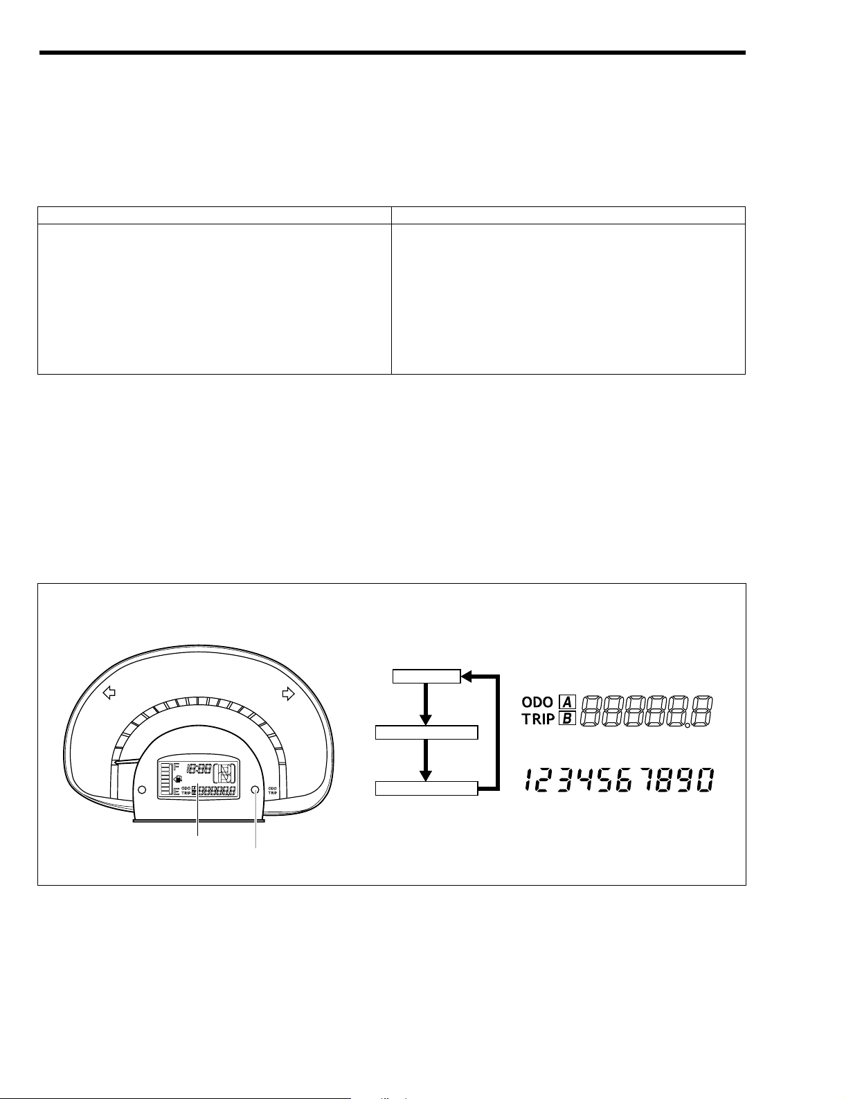
2-3 ODOMETER TRIP METER
2-3-1 DESCRIPTION
1.An excellent visibility is achieved by employing an odometer ; trip meter with LCD (Liquid Crystal
Display) indication.
2.As for the odometer ; trip meter, an electric type odometer ; trip meter equipped with a twin trip meter
has been employed.
3.The changing of each mode is done by pressing the selection switch at the right of the speedometer.
Indications are made in the order of odometer!trip meterA!trip meter B!odometer.
4.The figure of the trip meter is reset by pressing the selection switch for more than about one second.
Numeral pattern
Odometer
Trip meter A
Trip meter B
T11H1032ES16
Selection switch
LCD
Indication Function
Indication range: 0 - 8400 rpm (Red zone: 6800 - 8400 rpm) Electric type (pointer: stepper motor type)
Revolution signal source: EFI ECU
Number of input pulses: 2pulse/rev (100 Hz at 3000 rpm)
The pulse signal from the EFI ECU is inputted. Then, the tachometer counts the pulse signals and performs calculation
and finally indicates the engine revolution speed.
J3–9
Page 58

2-3-2 SPECIFICATIONS
2-4 FUEL GAUGE
2-4-1 DESCRIPTION
1.An excellent visibility is achieved by indicating fuel gauge
in LCD (Liquid Crystal Display).
2.The meter ECU calculates the accurate fuel level by calculating the average data of a certain period of time
based on the level signal from the fuel sender gauge.
3.The Fuel gauge indicates the fuel level by turning on/off of
the eight segments in the bar graph.
2-4-2 SPECIFICATIONS
2-4-3 FUEL LEVEL INDICATION FUNCTION
The meter ECU indicates the corresponding LCD segments by calculating the average data of a certain
period of time based on the level signal from the fuel sender gauge.
2-4-4 FUEL LEVEL WARNING FUNCTION
The driver is warned by the No.1 segment (bottom position) blinking when No.2 segment is turned off
(when the fuel level is about 6%).
Indication Function
Digital indication by LCD (Liquid Crystal Display)
Indicated by 8 segment bar graph.
Indication range: E - F
The fuel level is indicated by inputting the fuel sender gauge voltage and calculating at the meter ECU.
No.1 segment (bottom position) blinks when No.2 segment is
turned off (when fuel level is about 6%).
Indication Function
Digital indication by LCD
Indication range:
Odometer:
0 - 999999 km
0 - 999999 MILE
Trip meter A ; B:
0 - 9999.9 km
0 - 9999.9 MILE
LCD type
Mileage signal source:
ABS ECU [ABS-equipped vehicles]
A/T ECU [A/T vehicles without ABS]
Vehicle speed sensor (MRE type) [M/T vehicles without ABS]
The running distance is indicated by inputting the running distance signal from the ABS ECU over the CAN communication and
processing the signal at the meter ECU. (ABS-equipped vehicles)
The running distance is indicated by inputting the running distance signal from the A/T ECU over the CAN communication and
processing the signal at the meter ECU. (A/T vehicles without
ABS)
The running distance is indicated by inputting the running distance signal from the vehicle speed sensor (MRE type) and processing the signal at the meter ECU. (M/T vehicles without ABS)
The backward moving distance is also added.
By pressing the selection switch, indications are made in the order
of odometer!trip meter A !trip meter B.
By pressing the selection switch for more than about one second,
the figure of the trip meter is reset.
J3–10
T11H1033ET10
Fuel mark
No.8 segment
No.1 segment
Page 59

2-5 WARNING / INDICATOR
2-5-1 TURN
1.A turn indicator has been set in the meter.
2.It blinks when the turn signal switch and the hazard switch
are "ON".
2-5-2 HIGH-BEAM
1.A high-beam indicator is set in the meter.
2.It is lighted when the headlamp is set at high-beam or
passing.
2-5-3 CHARGE
1.A charge warning lamp is set in the meter.
2.If the charging system is normal, it is lighted when the IG
switch is turned "ON" and is turned off when the engine is
started.
3.It is constantly lighted when there is an abnormality in the
system.
2-5-4 OIL
1.An oil warning lamp has been set in the meter.
2.It is lighted when the oil pressure switch is "ON" and is
turned off when the engine is started.
3.It is constantly lighted when the oil pressure is low.
2-5-5 MIL
1.If the engine control system is normal, it is lighted when the
IG switch is turned "ON" and is turned off when the engine
is started.
2.It is constantly lighted when there is an abnormality in the
system.
3.The diagnosis code of the engine control system is outputted.
J3–11
H11H2052T10
H11H2053T10
H11H2054T10
H11H2055T10
H11H2056T10
Page 60

2-5-6 BRAKE
1.A brake warning lamp has been set in the meter.
2.If the system is normal, it is lighted when the IG switch is
turned "ON" and is turned off three seconds later under
the condition in which the parking brake is not operating.
3.It is lighted when the parking brake switch or the brake
fluid level switch is "ON".
4.It is constantly lighted when there is an abnormality in the
ABS.
2-5-7 ABS
1.An ABS warning lamp has been set in the meter.
2.If the system is normal, it is lighted when the IG switch is
turned "ON" and is turned off about three seconds later.
3.It is constantly lighted when there is an abnormality in the
system.
4.The diagnosis code of the ABS is outputted.
2-5-8 AIRBAG
1.An airbag warning lamp has been set in the meter.
2.If the system is normal, it is lighted when the IG switch is
turned "ON" and is turned off about six seconds later.
3.It is constantly lighted when there is an abnormality in the
system.
4.The diagnosis code of the airbag system is outputted.
2-5-9 EPS
1.An EPS warning lamp has been set in the meter.
2.If the system is normal, it is lighted when the IG switch is
turned "ON" and is turned off two seconds later.
3.It is constantly lighted when there is an abnormality in the
system.
4.The diagnosis code of the EPS system is outputted.
J3–12
W13C6012T10
S16C5061T10
L11A5009T10
L15C5002T10
Page 61

2-5-10 HIGH WATER TEMPERATURE/LOW WATER TEM-
PERATURE
1.A high water temperature warning lamp and low water
temperature indicator lamp have been set in the meter.
2.If the system is normal, the high temperature warning lamp
and low temperature indicator lamp are lighted when the
IG switch is turned "ON" and are turned off about three
seconds later under the condition in which the water temperature is neither high or low.
NOTE
•Even if the IG switch is turned "ON" when the engine
water temperature is low, the high water temperature
warning lamp is lighted for about three seconds for initial check. In that case, the low water temperature indicator lamp is also lighted and will continue to be lighted after three seconds until the engine water temperature becomes high.
3.The high water temperature warning lamp blinks when the
water temperature is about 117˚C or above and is turned
off when it is about 112˚C or below.
4.The low water temperature indicator lamp is lighted when
the water temperature is about 35˚C or below and is
turned off when it is about 40˚C or above.
J3–13
H11H2059T10
T11H1069ET10
COOL illuminated HOT illuminated
35$C40$C112$C117$C
Extinguished
ON
OFF
Page 62

2-5-11 SEAT BELT
(1) Description
1.A blinking type seat belt warning lamps have been set to the driver seat and the passenger seat
according to the specifications. As for the position of the warning lamp, the one of the driver seat is
set in the meter and the other for the passenger seat is set in the air conditioner control panel.
2.The driver seat belt warning lamp blinks if the seat belt is not fastened on the driver seat.
3.As for the front passenger seat belt warning lamp, it blinks if the seat belt is not fastened on the front
passenger seat when there is somebody seated on the passenger seat.
4.A passenger detection sensor which detects if the passenger is seated or not has been set below the
skin of the front passenger seat cushion.
T11H1034ES16
Driver's seat belt warning Front passenger seat belt warning
J3–14
Page 63

(2) Passenger detection sensor structure
When the IG switch is "ON" and a passenger seats on the front passenger seat, the electrodes of the sensor have contact and let the warning lamp blink. Then, when the passenger seat belt is fastened, the seat
belt switch is turned "OFF" and the warning lamp is turned off.
NOTE
• If a load above a certain level is applied to the seat cushion such as in the case of placing luggage
on the passenger seat cushion, the sensor may detect this.
2-5-12 O/D OFF
1.An O/D OFF indicator has been set in the meter.
2.It is lighted when the O/D is "OFF".
3.It blinks when there is an abnormality in the transmission
control system.
4.The diagnosis code of the transmission control system is
outputted.
2-5-13 SHIFT POSITION
1.A shift position indicator has been set in the LCD of the
meter.
2.The present shift position is indicated.
NOTE
• The frame indication blinks corresponding to the
buzzer interval during R range indication.
T04B1010ES20
A
A
Spacer
Electrode
Contact film
Section A(A
J3–15
T11H1036T10
H11H2058T10
Page 64

2-5-14 SECURITY
1.A security indicator has been set in the meter.
NOTE
• Please refer to the pages of the immobilizer system for
details concerning lighting conditions.
Refer to Page I4-13.
2.The diagnosis code of the immobilizer system is outputted.
2-5-15 REAR FOG LAMP
1.A rear fog lamp indicator has been set in the meter.
2.It is lighted when the rear fog lamp is lighted.
2-6 WARNING BUZZER
2-6-1 DESCRIPTION
1.A multi-buzzer is employed and incorporated in the meter. This multi-buzzer sounds while various
warnings are given such as when the key is remaining in the key cylinder, or when the reverse gear is
selected.
2-6-2 SPECIFICATIONS
2-7 CLOCK
1.A digital clock by LCD (Liquid Crystal Display) indication
has been employed.
2.An excellent usability has been achieved by setting the
installation position in the meter.
3.A clock adjusting switch to adjust the time has been set on
the left side of the clock.
Category Function
Key remaining in key cylinder
Light remaining to be illuminated
Reverse
Seat belt remaining (Europe specification)
Vehicle speed warning (Some specifications)
Warnings and abnormalities of each system are notified by sound.
J3–16
T11H1037T10
T11H1038T10
T11H1042ET10
Clock
Clock correction switch
Page 65
2-8 WATER TEMPERATURE INDICATION FUNC-
TION
2-8-1 DESCRIPTION
1.The water temperature may be indicated on LCD (Liquid
Crystal Display) by the following procedures.
(1) Turn "ON" the IG switch.
(2) Short the terminal ECU-T and terminal E of the DLC.
(3) Press on the selection switch for about a second.
CAUTION
• If the vehicle is driven with the terminal ECU-T ad terminal E of the DLC in the above (2) short-circuited, the
figures on the liquid crystal display will remain to indicate the water temperature until the vehicle speed is
above 8km/h and thus the odometer ; trip meter cannot be seen. Please remove the short circuit between
the terminal ECU-T and terminal E when the operation
is finished.
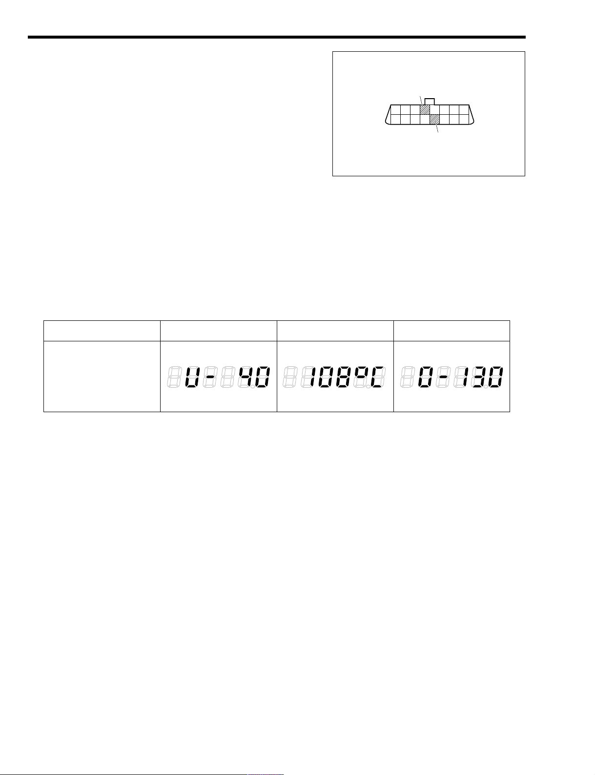
2.The temperature indicated on the LCD (Liquid Crystal Display) is from 40Ç to 130Ç with 1Ç intervals.
Water temperature
Indication example
40$C or less 130$C or more
108$C
T11H1040ES10
J3–17
H11A5014T10
E
ECU-T
Page 66

2-9 CAN COMMUNICATION
For the meter ECU in the meter, CAN communication is employed for some of the communications with
other ECU's.
Please refer to the pages of the CAN communication system for the CAN communication.
Refer to Page L2-1.
2-10 LIN COMMUNICATION
For the meter ECU in the meter, the LIN communication is
employed for some of the communications with other ECU's.
Please refer to the pages of the LIN communication system
for the LIN communication.
Refer to Page L2-13.
Contents of meter ECU communication (LIN communication)
Meter ECU
Nomenclature of signals
Receiving Sending
Applicable ECU
ITC sleep refusal <( ITC
Request of keyless door lock (< ITC
Request of keyless door unlock (< ITC
Key switch (< ITC
Terminal ECU-T (< ITC
Door courtesy switch (< ITC
T11H1527ES25
A/T ECU Meter ECU ABS ECU
EFI ECU
Shift range information
O/D OFF lamp demand
A/T warning demand
Completion of A/T
learning value erasure
Vehicle speed
Brake warning lamp demand
ABS warning lamp demand
Engine cooling water temperature
Tail switch
Vehicle speed (Meter)
Running distance
ECU-T terminal ECU-T terminal
J3–18
B11H1022ET10
Meter ECU ITC
Page 67

2-11 DIAGNOSIS (ONBOARD DIAGNOSIS FUNCTION)
This is a function whereby the ECU informs the inspection operator of the abnormal items when there has
been a failure in the system. When failure takes place, the ECU memorizes the abnormal item.
Please refer to the repair manual for details concerning the diagnosis.
2-12 FAIL-SAFE FUNCTION
When an abnormality takes place in each function, the meter shifts to the fail mode and carries out the
processes as in the following.
List of fail mode
Function Abnormality item Process when failure takes place
Vehicle speed signal (CAN) communication disabled
Indicates 0km/h
Speedometer
Abnormality in the meter Indicates 0km/h
Vehicle speed signal (CAN) communication disabled
Does not integrate mileage
Odometer
Abnormality in the meter
; Does not integrate mileage
; Indicates "ODO" on the LCD.
; Blinks indication of integrated mileage figure
;The running distance is measured in the unit of km.
Either of the above is done.
Vehicle mileage signal (CAN) communication disabled
Does not integrate mileage
Trip meter
Abnormality in the meter
; Blinks indication of integrated mileage figure
;The running distance is measured in the unit of km.
Either of the above is done.
Fuel gauge Signal analog / digital conversion error
Turns off of all segments until the IG switch is turned "ON"
again.
Multiple receiving of shift range information
signal (CAN)
Turns off of the shift position indication and blinking of the
frame indication only
Shift position
indicator
Shift range information signal (CAN) communication disabled
Turns off of the shift position indication and blinking of the
frame indication only
High water
temperature
warning lamp/
Low water
temperature
indicator lamp
Engine water temperature signal (CAN)
communication disabled
High water temperature warning lamp extinguished
Low water temperature indicator lamp blinking
O/D OFF lamp request signal (CAN) communication disabled
Indicator extinguished
O/D OFF indicator
A/T warning request signal (CAN) communication disabled
Indicator extinguished
Brake
warning lamp
Brake warning lamp request signal (CAN)
communication disabled
Lamp illuminated
ABS
warning lamp
ABS warning lamp request signal (CAN)
communication disabled
Lamp illuminated
Reverse
warning buzzer
Multiple receiving of shift range information
signal (CAN)
Buzzer sound stopped
J3–19
TO INDEX TO NEXT SECTION
Page 68

OUTLINE------------------------------------------ J2 - 1
DESCRIPTION ------------------------------- J2 - 1
SYSTEM WIRING DIAGRAM ------------ J2 - 3
CONSTRUCTION AND OPERATION----- J2 - 5
FRONT WIPER------------------------------- J2 - 5
REAR WIPER--------------------------------- J2 - 8
WASHER--------------------------------------- J2 - 9
J2 WIPER & WASHER
J2
TO INDEX
Page 69

1OUTLINE
1-1 DESCRIPTION
1.Improvements have been made in the downward field of view and the interior appearance of the arm
by positioning the front wiper system lower than the previous model.
2.The appearance and the workability when replacing the blade has been improved by employing the
U-hook type for the tightening of the front wiper arm and the front wiper blade.
3.The frame integrated module type has been employed for the installation structure of the front wiper
motor and the front wiper link. As a result, the system rigidity has been enhanced, thus reducing the
wiper operation sound as well as the variation of the wiper sweep angle.
4.Careful consideration has been made for the protection of pedestrians by employing a pivot section
breaking structure for the front passenger seat side wiper.
5.The rear wiper which has a plastic arm and blade has been provided on some specifications.
6.Two 1-hole type washer nozzles have been set in the front and one 1-hole type washer nozzle has been
set in the rear side.
T11H1020ES25
Front wiper motor & link
Washer tank
Front washer nozzle
Front wiper arm & blade
Windshield wiper switch
J2–1
Page 70

The illustration represents the RHD vehicle.
T11H1021ES25
Rear washer nozzle
Rear wiper arm & blade
Rear wiper motor
J2–2
Page 71

1-2 SYSTEM WIRING DIAGRAM
1-2-1 FRONT WIPER & WASHER
T11H1536ES25
M
M
HI
LO
INT
OFF
MIST
OFF
ON
P
WB '2 '1 'S INT1 INT2 B1
T
P
T
WEW
Wiper switch
Front wiper switch
Washer switch
Wiper relay
Washer motor
Wiper motor
R1
R6
R7
R8
R5
LO
HI
C1
C2
ZD
R3
R2
R4
D1
Tr1
Tr2
WIPER
IG relay
IG1
F/L
J2–3
Page 72

1-2-2 REAR WIPER & WASHER (VEHICLES WITHOUT INTERMITTENT FUNCTION)
1-2-3 REAR WIPER & WASHER (VEHICLES WITH INTERMITTENT FUNCTION)
T11H5605ES16
F/L
IG1
IG relay
WIPER
M
2
M
2
2
1
2 6 5 4 3
3 1 2
3
1
P
T
Washer motor
Rear wiper switch
Rear wiper motor
Rear wiper relay
WR CIR '1R EW
WASH
OFF
INT
ON
ON WASH
5
Intermittent
control circuit
T11H1537ES16
ON WASH
ON
OFF
WASH
P
WR '1R EW
T
Washer motor
Rear wiper switch
Rear wiper motor
M
IG relay
WIPER
IG1
F/L
M
J2–4
Page 73

2CONSTRUCTION AND OPERATION
2-1 FRONT WIPER
2-1-1 DESCRIPTION
1.The module type wiper motor & link has been employed for the front wiper.
2.Careful consideration has been made for the protection of pedestrians by employing a breaking structure for the front passenger seat side pivot section.
2-1-2 FRONT WIPER MOTOR AND LINK
The frame integrated module type has been employed for the installation structure of the front wiper motor
and the front wiper link. As a result, the system rigidity has been enhanced, thus reducing the wiper operation sound as well as the variation of the wiper sweep angle.
2-1-3 FRONT WIPER MOTOR
For the front wiper motor, a motor with rated voltage of 12V and rated torque of 18N;m has been employed
for all models.
Specification table
2-1-4 FRONT WIPER ARM & BLADE
Specification table
Driver seat side
front wiper blade length (mm)
500
Front passenger seat side
front wiper blade length (mm)
400
Rated voltage (V) 12
Rated torque (N;m) 18
T11H1027S16
J2–5
Page 74

2-1-5 FRONT WIPER LINK
1.Careful consideration has been made for the protection of pedestrians by employing the pivot section
breaking structure for the front passenger seat side wiper.
2.A structure in which it is difficult for the head of the pedestrian to hit the base of the wiper directly has
been employed by positioning the hood higher than the base of the wiper.
3.Even in the event that the vehicle and the pedestrian collide and the pedestrian hit the base of the
wiper, the pivot shaft falls off downward and reduces the impact by the breaking of the pivot section
due to the impact.
T11H1028ES16
A
A
3Section A(A5
Pivot normal position
Pivot dropping position
Pivot rupture construction
J2–6
Page 75

2-1-6 WINDSHIELD WIPER SWITCH
By positioning the headlamp dimmer switch and the windshield wiper switch independently, replacement
of the windshield wiper switch has been made possible without removing the steering wheel. In this way,
the serviceability has been enhanced.
T11H1541ES16
Automatic
restoration
Automatic
restoration
Automatic
restoration
Rear wiper switch
Front wiper switch
Windshield wiper switch
REAR
ON
MIST
PULL
OFF
INT
INT
LO
HI
OFF
MIST
OFF
INT
LO
HI
WASH
ON
WASH
INT
ON
OFF
T11H1006ES16
Windshield wiper switch
Steering column
bracket
Headlamp dimmer switch
Hook
Hook
J2–7
Page 76

2-2 REAR WIPER
2-2-1 DESCRIPTION
Individual replacement of the rear wiper blade has been made possible by letting the rear wiper arm and
the blade have separate body structure made of resin.
2-2-2 REAR WIPER MOTOR
The rear wiper motor is common for all models.
Specification table
2-2-3 REAR WIPER ARM & BLADE
1.Individual replacement of the rear wiper blade has been made possible by letting the rear wiper arm
and the rear wiper blade have separate body structure made of resin.
2.The rear wiper arm and the rear wiper blade have the specification common for all models.
Specification table
2-2-4 REAR WIPER SWITCH
For easier operation, the rear wiper switch has been integrated with the front wiper switch.
T11H1541ES16
Automatic
restoration
Automatic
restoration
Automatic
restoration
Rear wiper switch
Front wiper switch
Windshield wiper switch
REAR
ON
MIST
PULL
OFF
INT
INT
LO
HI
OFF
MIST
OFF
INT
LO
HI
WASH
ON
WASH
INT
ON
OFF
Rear wiper blade length (mm) 350
Rated voltage (V) 12
Rated torque (N;m) 7
J2–8
Page 77

2-3 WASHER
2-3-1 WASHER TANK & PUMP
1.The washer tank has been positioned below the right headlamp.
2.A wash tank of 2.0% and pump have been employed for all models.
Specification table
2-3-2 WASHER NOZZLE
1.Two 1-hole type washer nozzle has been set in the front and one 1-hole type washer nozzle has been
set in the rear side.
2.A stable cleaning performance during high speed driving has been achieved by setting two washer
nozzles in the front.
T11H1529S20
Tank capacity (%) 2.0
Rated voltage (V) 12
Current when in use (A) Not to exceed 2.0
Pump injection pressure (kPa) 150&30
Injection flow rate (%/minute) 1.1 or more
J2–9
TO INDEX TO NEXT SECTION
Page 78

OUTLINE------------------------------------------ J1 - 1
CONSTRUCTION AND OPERATION----- J1 - 3
HEADLAMP ----------------------------------- J1 - 3
FRONT FOG LAMP ------------------------- J1 - 6
REAR FOG LAMP --------------------------- J1 - 6
TURN SIGNAL AND HAZARD LAMP-- J1 - 7
STOP LAMP ---------------------------------- J1 - 8
TAIL LAMP & ILLUMIN ATION ------- ----- J 1 - 9
BACKUP LAMP----------------------------- J1 - 10
ROOM LAMP-------------------------------- J1 - 10
J1 LIGHTING
J1
TO INDEX
Page 79

1OUTLINE
1.Two-headlamp type halogen headlamps have been selected.
2.For the headlamps, unconventional multi-reflector type that has enhanced the photometric performance has been employed.
3.The manual headlamp leveling mechanism is provided on some specifications.
4.An excellent appearance has been achieved by employing clear lenses for outer lenses of the front,
side and rear turn signal lamps. In addition to the employment of the clear lens, amber bulbs have
been employed for the front, and rear turn signal lamps and amber caps for the interior of the side turn
signal lamps.
5.High-mount stop lamps equipped on the back door have been set in some specifications.
6.An excellent appearance has been achieved by employing clear lenses for the outer lenses of the rear
combination lamp.
7.The rear fog lamp has been set in some specifications and is provided in the driver seat side rear combination lamp.
3
1
2
5
4
13
14
15
6
7
8
9
10
11
12
T11H1501S25
J1–1
Page 80

Specification table
No. Nomenclature Category Capacity (W)
1 Headlamp H4 60/55
2 Clearance lamp T10 5
3 Front turn signal lamp S25 (Amber) 21
4 Front fog lamp HB4 51
5 Side turn signal lamp T10 5
6 Tail and stop lamp T20 21/5
7 Rear turn signal lamp T20 (Amber) 21
8 Backup lamp T16 16
9 Rear fog lamp T20 21
10 Reflex reflector ((
11 License plate lamp T10 5
12 High-mount stop lamp T16 16
13 Front map lamp ( 8
14 Room lamp ( 8
15 Luggage room lamp ( 5
J1–2
Page 81

2CONSTRUCTION AND OPERATION
2-1 HEADLAMP
2-1-1 DESCRIPTION
1.Two-headlamp type halogen headlamps have been selected.
2.The multi-reflector type that has enhanced the photometric performance has been employed.
3.A combination lamp that has integrated the front turn signal lamp and the clearance lamp has been
employed.
4.The manual headlamp leveling mechanism is provided on some specifications.
2-1-2 SYSTEM WIRING DIAGRAM
(1) Headlamp
T11H1004ES25
OFF
P
T
EL H
P
T
HELHUHL
Lighting switch
Dimmer passing switch
Headlamp dimmer switch
Headlamp
relay
H-LP RHH-LP LH
High beam
indicator
H
EL
Headlamp
Passing
Low beam
High beam
HU HL
F/L
Headlamp LH Headlamp RH
Low beam Low beam
High beam High beam
T11H1502ES10
A
A
3Section A - A5
J1–3
Page 82

(2) Manual headlamp leveling mechanism
Lighting switch
Headlamp dimmer switch
OFF
P
T
EL H
H
EL
Headlamp
T11H1503ES25
Headlamp relay
Headlamp
leveling actuator
LH
To Headlamp LH
H-LP LH
F/L
Headlamp
leveling actuator
RH
Headlamp
leveling switch
J1–4
Page 83

2-1-3 HEADLAMP DIMMER SWITCH
1.Replacement of the headlamp dimmer switch has been made possible without removing the steering
wheel by positioning the headlamp dimmer switch and the windshield wiper switch independently.
2.A mechanism in which the headlamp dimmer switch is directly fixed to the steering column bracket
with a hook has been employed. This has enhanced serviceability.
3.A turn canceling mechanism has been built in the headlamp dimmer switch.
2-1-4 MANUAL HEADLAMP LEVELING MECHANISM
1.Some specifications employ the manual headlamp leveling mechanism whereby the vertical direction
of the photometric axis can be adjusted from the vehicle interior as the vehicle posture changes due
to a loaded state. This mechanism can help avoiding dazzling the coming vehicles and vehicles running ahead.
2.Depending upon the state signal of the headlamp leveling switch in the vehicle interior (the highest
direction in the level 0, the lowest direction in the level 5), the headlamp leveling actuator is driven.
Thus, the reflector direction is changed vertically so as to adjust the photometric axis.
3.The headlamp leveling actuator is provided at the rear of the headlamp.
T11H1504ES10
A
A
3Section A - A5
Reflector
Headlamp
leveling actuator
T11H1007ES10
OFF
Tail, headlamp switch
Tail
Headlamp
Headlamp dimmer switch
T11H1006ES16
Windshield wiper switch
Steering column
bracket
Headlamp dimmer switch
Hook
Hook
J1–5
Page 84

2-1-5 HEADLAMP LEVELING SWITCH
It is installed at the side of the steering column.
2-2 FRONT FOG LAMP
2-2-1 DESCRIPTION
The round shaped front fog lamp is provided on some specifications.
2-2-2 SYSTEM WIRING DIAGRAM
2-2-3 FRONT FOG LAMP SWITCH
For easy operation, this switch has been integrated with the
headlamp dimmer switch.
2-3 REAR FOG LAMP
2-3-1 DESCRIPTION
The rear fog lamp has been set in some specifications and is built in the driver seat side rear combination lamp.
F/L TAIL
Tail lamp switch
Fog lamp relay
FOG LH
FOG RH
FR fog lamp switch
FR fog lamp RHFR fog lamp LH
To tail lamp circuit
IG1
T11H1507ES16
J1–6
T11H1505T10
Front fog lamp switch & Rear fog lamp switch
T11H1509ET10
Page 85

2-3-2 SYSTEM WIRING DIAGRAM
The rear fog lamp switch can be turned ON only when the headlamp or front fog lamp is illuminated.
2-3-3 REAR FOG LAMP SWITCH
For easy operation, this switch has been integrated with the
headlamp dimmer switch.
2-4 TURN SIGNAL AND HAZARD LAMP
2-4-1 DESCRIPTION
1.The front turn signal lamp has been built in the combination headlamp.
2.Other than its primary usage, the hazard lamp serves as an answer back function for the keyless entry
system
*
.
*
Refer to Page I4-6.
2-4-2 HAZARD SWITCH
1.The switch has employed a push type that incorporates
night illumination.
2.For easier operation, it is provided at the central section of
the heater control panel.
Tail lamp switch
Rear fog lamp switch
TAIL
F/L
Rear fog lamp
Rear fog lamp indicator
T11H1508ES16
J1–7
Front fog lamp switch & Rear fog lamp switch
T11H1509ET10
T11H1012T10
Page 86

2-4-3 FLASHER RELAY
This is of an insertion type into the fuse block.
Specification table
2-5 STOP LAMP
2-5-1 DESCRIPTION
A high-mount stop lamp equipped on the back door has been set in some specifications.
2-5-2 SYSTEM WIRING DIAGRAM
2-5-3 STOP LAMP SWITCH
1.The stop lamp switch is installed in the upper part of the
brake pedal and it detects that the brake pedal is
depressed.
2.It becomes "ON" when the brake pedal is depressed.
To ABS ECU
To EFI ECU
Stop lamp
switch
Stop lamp
RH
Stop lamp LH
F/L
STOP
T11H1013ES16
High-mount stop lamp
Number of flashing
during normal operation
85&10 (times/minute)
Number of flashing
when one lamp is burnt out
140 - 250 (times/minute)
J1–8
T11H1534T10
T11H1510T10
M21C3225T10
Page 87
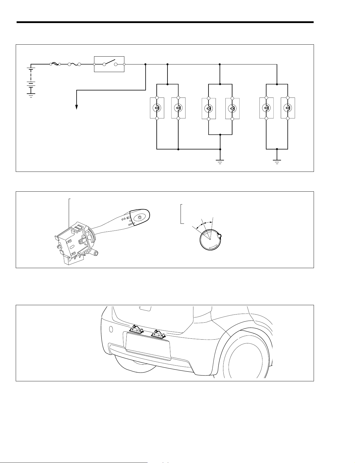
2-6 TAIL LAMP & ILLUMINATION
2-6-1 SYSTEM WIRING DIAGRAM
2-6-2 TAIL LAMP SWITCH
It is positioned in the headlamp dimmer switch.
2-6-3 LICENSE PLATE LAMP
1.The installation position of the license plate lamp is at the back door and the downward illumination
type has been employed.
2.A two-lamp type has been employed for the lamps.
2-6-4 MULTI-TRAY ILLUMINATION
Refer to Page I2-5.
T11H1512S10
T11H1007ES10
OFF
Tail, headlamp switch
Tail
Headlamp
Headlamp dimmer switch
Tail lamp switch
To each illumination
F/L TAIL
License plate lamp
Tail lamp RH
Tail lamp LH
Clearance lamp RH
Clearance lamp LH
T11H1511ES16
J1–9
Page 88
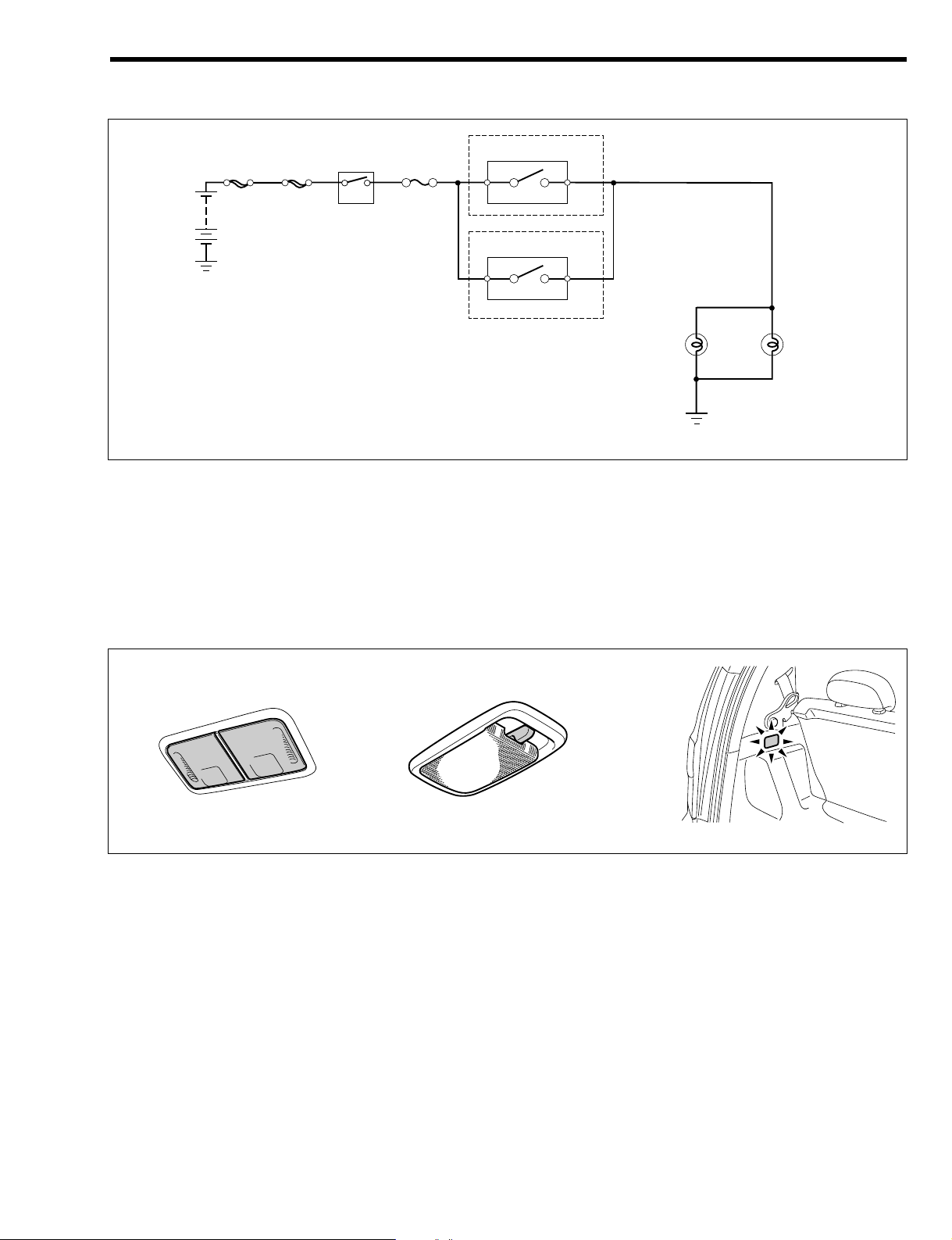
2-7 BACKUP LAMP
2-7-1 SYSTEM WIRING DIAGRAM
2-8 ROOM LAMP
2-8-1 DESCRIPTION
1.As for the interior lighting, the front map lamp, room lamp and luggage room lamp have been employed
for all models.
2.The convenience has been enhanced by employing a room lamp timer function for the room lamp and
luggage room lamp.
3.Other than its primary usage, the room lamp and the luggage room lamp serve as an answer back
function for the keyless entry system
*
.
*
Refer to Page I4-6.
T11H1018ES10
O
N
OFF
DOOR
Front map lamp Room lamp Luggage room lamp
Neutral start switch
Backup lamp switch
AM1
IG switch
F/L
IG1/BACK
IG1
R
A/T vehicle
M/T vehicle
T11H1513ES16
Backup lamp LH
Backup lamp RH
J1–10
Page 89

2-8-2 ROOM LAMP TIMER FUNCTION
1.When the following conditions are met, the room lamp and
the luggage room lamp are lighted for 15 seconds and
then fade away.
(1) Either of the door opened!all doors closed
2.When all of the following conditions are met, the room lamp and the luggage room lamp are lighted for
15 seconds and then fade away.
(1) IG switch "OFF"
(2) All doors closed (courtesy switch "OFF")
(3) Driver seat door lock (door control switch) "LOCK"!"UNLOCK"
3.If the driver seat door lock (door control switch) is changed to "LOCK" while the lamp is lighted under
the room lamp timer control, the light is dimmed to 50% of when it is lighted and then is faded away
three seconds later.
4.When the IG switch becomes "ON" during the room lamp timer control, it is faded away immediately.
2-8-3 BATTERY OVER-DISCHARGE PREVENTIVE FUNCTION
1.When all of the following conditions are met continuously for 10 minutes, the room lamp and the luggage room lamp are turned off.
(1) IG switch "OFF"
(2) Either of the door opened (courtesy switch "ON")
2.When either of the following conditions are met, the battery over-discharge preventive function is
released.
(1) IG switch "ON"
(2) All doors closed (courtesy switch "OFF")
2-8-4 ROOM LAMP LIGHTING FUNCTION AT TIME OF KEY REMOVAL
1.When all of the following conditions are met, the room lamp and the luggage room lamp are lighted for
15 seconds.
(1) All doors closed (courtesy switch "OFF")
(2) Elapse of 200ms or more since the recovery from sleep mode (low current mode) of ITC
(3) Key switch "ON" (inserted)!"OFF" (not inserted)
2.When the IG switch becomes "ON", it fades away immediately.
NOTE
•After 10 minutes or more have passed since the IG switch has been "OFF", if the key switch
changes from "ON" (inserted)!"OFF" (not inserted), the room lamp lighting mechanism at time of
key removal does not take control.
CAUTION
•When other room lamp control conditions are met while the room lamp lighting control at time of
key removal is in operation, it makes transition to the other control.
J1–11
100
80
50
25
0 16151442
Lamp brightness (%)
Time (sec)
<Bright specification>
15.0sec 0.6sec
N11B1025ET16
Page 90

2-8-5 COURTESY SWITCH
For the courtesy switches on the front door and the rear door, a shape that has the main body switch section and the cushion section integrated has been employed with the aim of enhancing the waterproofing
property. This switch directly connects the main body and the connector.
Additionally, as for the back door, the back door lock Ay serves for the courtesy switch function.
Back door
Back door lock Ay
Front door , Rear door
T11H1019ES10
J1–12
TO INDEX TO NEXT SECTION
Page 91

DOOR LOCK SYSTEM ---------------------------- I4 - 1
OUTLINE ------------------------------------------ I4 - 1
POWER DOOR LOCK SYSTEM --------------- I4 - 1
OUTLINE ------------------------------------------ I4 - 1
DESCRIPTION-------------------------------- I4 - 1
SYSTEM DRAWING ------------------------ I4 - 1
SYSTEM WIRING DIAGRAM ------------- I4 - 2
LOCATION OF COMPONENTS---------- I4 - 4
CONTROL----------------------------------------- I4 - 5
KEY LOCKING PREVENTION
SYSTEM ---------------------------------------- I4 - 5
WAKE-UP/SLEEP FUNCTION ----------- I4 - 5
COMPONENTS---------------------------------- I4 - 5
BODY INTEGRATED CONTROLLER
(ITC)---------------------------------------------- I4 - 5
COMBINATION METER-------------------- I4 - 5
KEY-LESS ENTRY SYSTEM -------------------- I4 - 6
OUTLINE ------------------------------------------ I4 - 6
DESCRIPTION-------------------------------- I4 - 6
SYSTEM DRAWING ------------------------ I4 - 6
SYSTEM WIRING DIAGRAM ------------- I4 - 7
LOCATION OF COMPONENTS---------- I4 - 9
CONTROL --------------------------------------- I4 - 10
BASIC FUNCTION ------------------------- I4 - 10
AUTOMATIC LOCKING FUNCTION -- I4 - 10
AJAR DOOR PREVENTING
FUNCTION ----------------------------------- I4 - 10
KEY REMAINING REMINDER
FUNCTION ----------------------------------- I4 - 10
ANSWER BACK FUNCTION ------------ I4 - 10
WAKE-UP/SLEEP FUNCTION---------- I4 - 10
COMPONENTS -------------------------------- I4 - 11
TRANSMITTER------------------------------ I4 - 11
KEYLESS RECEIVER --------------------- I4 - 11
BODY INTEGRATED
CONTROLLER(ITC) ----------------------- I4 - 12
COMBINATION METER ------------------ I4 - 12
COURTESY SWITCH --------------------- I4 - 12
ROOM LAMP -------------------------------- I4 - 12
TURN SIGNAL LAMP --------------------- I4 - 12
IMMOBILIZER SYSTEM------------------------- I4 - 13
OUTLINE----------------------------------------- I4 - 13
DESCRIPTION ------------------------------ I4 - 13
NOTES ON IMMOBILIZER SYSTEM - I4 - 13
SYSTEM DRAWING ----------------------- I4 - 13
SYSTEM WIRING DIAGRAM ----------- I4 - 14
LOCATION OF COMPONENTS -------- I4 - 15
CONTROL --------------------------------------- I4 - 16
BRIEF DESCRIPTION OF
OPERATION --------------------------------- I4 - 16
IMMOBILIZER SYSTEM CONTROL -- I4 - 16
TRANSPONDER COMMUNICATION
CONTROL ------------------------------------ I4 - 17
EFI ECU COMMUNICATION
CONTROL ----------------------------------- I4 - 17
DIAGNOSIS ---------------------------------- I4 - 17
COMPONENTS -------------------------------- I4 - 18
IGNITION KEY ------------------------------ I4 - 18
IMMOBILIZER ECU ------------------------ I4 - 18
IMMOBILIZER COIL ----------------------- I4 - 18
EFI ECU--------------------------------------- I4 - 19
COMBINATION METER ------------------ I4 - 19
I4 DOOR LOCK & THEFT DETERRENT
I4
TO INDEX
Page 92

ÄÄ
DOOR LOCK SYSTEM
1OUTLINE
1.The power door lock is provided on all the models.
Refer to Page I4-1.
2.The LIN communication system is employed in a part of the door lock system circuit.
3.The body integrated controller (ITC) is directly attached to the fuse block.
4.The radio wave type keyless entry system is provided on some specifications. The "LOCK" and
"UNLOCK" operations for the front doors, rear doors and back door can be performed by the remote
control operation.
Refer to Page I4-6.
ÄÄ
POWER DOOR LOCK SYSTEM
1OUTLINE
1-1 DESCRIPTION
1.The power door lock is fitted to all vehicles as standard. The front passenger seat door, right and left
rear doors and back door can be locked and unlocked interlocking with the lock lever at the driver's
seat door or the key cylinder operation.
2.The LIN communication system is employed in a part of the system circuit.
1-2 SYSTEM DRAWING
Contents of multiplex communication control
*1
Refer to Page I4-5.
Sending Receiving Nomenclature of signals Contents of control
Meter ECU ITC Signal of terminal ECU-T ECU-T terminal check control
ITC Meter ECU Sleep non-permission signal Sleep (low current mode) transfer prohibition
*1
T11B1064ES20
Body integrated controller
(ITC)
LIN
communication
Courtesy switch
Key switch
Driver's seat
door lock switch
Combination meter
(Incorporating the meter ECU)
Door lock motor
I4–1
Page 93

1-3 SYSTEM WIRING DIAGRAM
Computer connector terminal arrangement diagram
ITC (fuse block side)
18 17 16 15 14 13 12 11 10 9 8 7 6 5 4 3 2 1
ITC
1 2 3 4 5 6 7 8 9 10 11 12 13 14 15 16 17 18
M21B5015ES10
ON
ECUB GND
HZD
+B IG LL LR EL ER EHW
GND
IG SW
ST
ACC
F/L AM1
AM2
HORN
HAZ
IG1/
BACK
D/
LOCK
BACK UP
IG1
IG2
Fuse block
MMM
Front left
Front right
Rear right
Rear left
Back
Room lamp
DOOR
OFF
5
LKS11UKS8ULM15IG1
7
CRL
3
9
BDR1
17 1
MPX
LIN communication line
6
M
LKM
16
Luggage room lamp
M
Flasher relay
ITC
Turn L
Turn R
Turn SW
Hazard SW
LH
RH
Driver's seat door control switch
Lock
Unlock
IG1
DOME
DLC
Combination Meter
LIN
ECU-T
Meter ECU
Courtesy switch
Front left
Front right
Rear right
Rear left
BACK
T11B1061ES25
Key switch
Battery
I4–2
Page 94

Body integrated controller (ITC) terminal name
Terminal No. Terminal code Terminal name
1 GND Earth
2 ((
3 CRL Room lamp driving output
4 ((
5 HZD Hazard lamp driving output
6 MPX LIN communication input/output
7 IG1 ECU power supply
8 UKS Door control unlock side switch input
9 ECU B ECU power supply
10 ((
11 LKS Door control lock side switch input
12 ((
13 ((
14 ((
15 ULM Door lock motor unlock side output
16 LKM Door lock motor lock side output
17 BDR1 Power supply
18 ((
I4–3
Page 95

1-4 LOCATION OF COMPONENTS
a Body integrated controller (ITC)
b Meter ECU
c Front door lock motor
d Rear door lock motor
e Back door lock motor
f Front door courtesy switch
g Rear door courtesy switch
h Back door courtesy switch
c
d
b
e
h
d
c
f
a
g
g
f
T11B1504S33
I4–4
Page 96
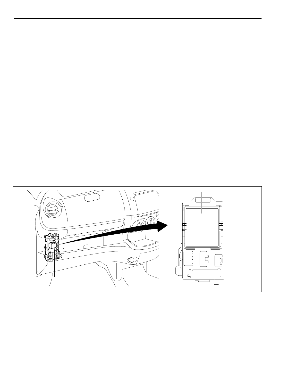
2CONTROL
2-1 KEY LOCKING PREVENTION SYSTEM
1.When all of the following conditions are met, after the door locking procedure has been completed, the
door locks are immediately unlocked, thus preventing the key from being locked in.
(1) The key is inserted into the ignition key cylinder. (Key switch is "ON".)
(2) Any of the doors are open. (Courtesy switch is "ON".)
(3) When the driver's seat door lock knob is switched from "UNLOCK" to "LOCK". (Driver's seat door
control switch is switched from "UNLOCK" to "LOCK".)
2.When all of the following conditions are met and 1 second has elapsed, the door locks are unlocked
thus preventing the key from being locked in.
(1) The key is inserted into the ignition key cylinder. (Key switch is "ON".)
(2) The ignition switch is set to "ACC" or "LOCK".
(3) The driver's seat door lock knob is at the "LOCK". (Driver's seat door control switch is set to
"LOCK".)
(4) Any door is open. !All doors are closed. (Courtesy switch is switched from "ON" to "OFF".)
2-2 WAKE-UP/SLEEP FUNCTION
The body integrated controller has a wake-up/sleep function in order to reduce the current used when the
ignition is switched to "ACC" or "LOCK".
3COMPONENTS
3-1 BODY INTEGRATED CONTROLLER (ITC)
1.It is attached to the reverse side of the fuse block on the lower left hand side of the instrument panel.
2.The ITC receives a signal from the driver's seat door lock switch and controls the power door lock
motor.
3-2 COMBINATION METER
Signals, such as the ECU-T terminal signal, are sent over the LIN communication line to the ITC from the
meter ECU in the combination meter.
1 Fuse block
2 Body integrated controller (ITC)
2
1
1
T11B1529ES16
3Reverse side5
I4–5
Page 97

ÄÄ
KEY-LESS ENTRY SYSTEM
1OUTLINE
1-1 DESCRIPTION
1.The radio wave type keyless entry system is provided on some specifications. The "LOCK" and
"UNLOCK" operations for the front doors, rear doors and back door can be performed by the remote
control operation.
2.The remote control of locking all the doors is possible by pushing the switch of the transmitter which is
apart from the key, thus sending weak waves.
3.The operation range of remote control is approx. 3 meters in radius from the center of the vehicle.
However, the range might be reduced or the function could be disabled due to the battery drain,
strong radio wave or noise. Also the operation range might be affected by the shape of the vehicle.
4.The LIN communication system is employed in a part of the system circuit.
1-2 SYSTEM DRAWING
Contents of LIN communication control
*1
Refer to Page J1-10.
*2
Refer to Page I4-5.
Sending Receiving Signal Nomenclature Contents of control
Keyless door lock signal Door lock, answer back control
Keyless door unlock signal Door unlock, answer back control
Key switch signal Key locked in prevention control
Meter ECU ITC
Door courtesy switch signal Room lamp control
*1
ITC Meter ECU Sleep non-permission signal Sleep (low current mode) transfer prohibition
*2
T11B1519ES20
Room lamp
Body Integrated Controller
(ITC)
Keyless receiver
Transmitter
LIN
communication
Turn signal lamp
Courtesy switch
Key switch
Driver's seat
door lock switch
Combination meter
(Incorporating the meter ECU)
Flasher relay
Door lock motor
I4–6
Page 98

1-3 SYSTEM WIRING DIAGRAM
Computer connector terminal arrangement diagram
321
87654
T11B8511ES16
ITC fuse block side
Keyless reciever
18 17 16 15 14 13 12 11 10 9 8 7 6 5 4 3 2 1
ITC
1 2 3 4 5 6 7 8 9 10 11 12 13 14 15 16 17 18
ON
ECUB GNDHZD
+B IG LL LR EL ER EHW
GND
IG SW
ST
ACC
F/L AM1
AM2
HORN
HAZ
IG1/
BACK
D/
LOCK
BACK UP
IG1
IG2
Courtesy switch
Fuse block
MMM
Front left
Front left
Front right
Front right
Rear right
Rear right
Rear left
Rear left
Back
BACK
Room lamp
DOOR
OFF
5
LKS11UKS8ULM15IG1
7
CRL
3
9
BDR1
17 1
MPX
KEYKLSLIN
ECU-T CTY
Keyless
receiver
LIN communication
line
Combination Meter
6
M
LKM
16
Luggage room lamp
M
Flasher relay
ITC
DLC
Meter ECU
Turn L
Turn R
Turn SW
Hazard SW
LH
RH
Driver's seat door control switch
Lock
Unlock
8 4
5
IG1
DOME
T11B1508ES25
Key switch
Battery
I4–7
Page 99

Body integrated controller (ITC) terminal name
Receiver connector terminal name
Terminal No. Terminal code Terminal name
1 ((
2 ((
3 ((
4 GND Earth
5 SIG Keyless signal output
6 ((
7 ((
8 'B Receiver power supply
Terminal No. Terminal code Terminal name
1 GND Earth
2 ((
3 CRL Room lamp driving output
4 ((
5 HZD Hazard lamp driving output
6 MPX LIN communication input / output
7 IG1 ECU power supply
8 UKS Door control unlock side switch input
9 ECU B ECU power supply
10 ((
11 LKS Door control lock side switch input
12 ((
13 ((
14 ((
15 ULM Door lock motor unlock side output
16 LKM Door lock motor lock side output
17 BDR1 Power supply
18 ((
I4–8
Page 100

1-4 LOCATION OF COMPONENTS
a Body integrated controller (ITC)
b Meter ECU
c Keyless receiver
d Front door lock motor
e Rear door lock motor
f Back door lock motor
g Room lamp
h Luggage room lamp
i Front turn signal lamp
j Rear turn signal lamp
k Side turn signal lamp
l Front door courtesy switch
m Rear door courtesy switch
n Transmitter
d k
e
b
k
f
g
n
e
h
d
l
a
i
i
m
m
j
j
l
c
T11B1505S33
I4–9
 Loading...