


Daewoo DWM-8010, DWM-8020/P, DWM-8010/P, DWM-8020, DWM-7010 Service Manual
...
S/M No. :
Service Manual
Washing Machine
Model: DWM-8010/P
DWM-8020/P
DWM-8010
DWM-8020
JAN. 2003

AUTO WASHER AUTO WASHER AUTO WASHER AUTO WASHER AUTO WASHER AUTO WASHER AUTO WASHER AUTO WASHER AUTO WASHER AUTO
WASHER AUTO WASHER AUTO WASHER AUTO WASHER AUTO WASHER AUTO WASHER AUTO WASHER AUTO WASHER AUTO WASHER AUTO WASHER
AUTO WASHER AUTO WASHER AUTO WASHER AUTO WASHER AUTO WASHER AUTO WASHER AUTO WASHER AUTO WASHER AUTO WASHER AUTO
WASHER AUTO WASHER AUTO WASHER AUTO WASHER AUTO WASHER AUTO WASHER AUTO WASHER AUTO WASHER AUTO WASHER AUTO WASHER
AUTO WASHER AUTO WASHER AUTO WASHER AUTO WASHER AUTO WASHER AUTO WASHER AUTO WASHER AUTO WASHER AUTO WASHER AUTO
WASHER AUTO WASHER AUTO WASHER AUTO WASHER AUTO WASHER AUTO WASHER AUTO WASHER AUTO WASHER AUTO WASHER AUTO WASHER
AUTO WASHER AUTO WASHER AUTO WASHER AUTO WASHER AUTO WASHER AUTO WASHER AUTO WASHER AUTO WASHER AUTO WASHER AUTO
WASHER AUTO WASHER AUTO WASHER AUTO WASHER AUTO WASHER AUTO WASHER AUTO WASHER AUTO WASHER AUTO WASHER AUTO WASHER
WASHING MACHINE
CCoonntteennttss
1. SPECIFICATIONS ..................................................................................................... 1
2. EXTERNAL VIEW ..................................................................................................... 2
3. PRINCIPLES OF OPERATION AND EXPLANATION OF FUNCTIONS................ 3
4. DIRECTION FOR DISASSEMBLY AND ASSEMBLY ..............................................7
5. TROUBLESHOOTING GUIDE ................................................................................10
6. EXPLODED VIEW AND PARTS LIST.....................................................................15
7. WIRING DIAGRAM ..................................................................................................23
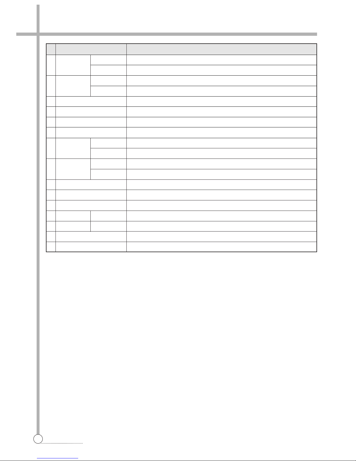
NO. ITEM SPECIFICATIONS
1 POWER VOLTAGE AC 127V
SOURCE FREQUENCY 60Hz
2 POWER WASH 330W
CONSUMPTION
SPIN 180W
3 DIMENSION NET : 813X500X930, PACKED UP : 830X530X970 (WXDXH)
4 MACHINE WEIGHT NET : 29kg, PACKED UP : 32kg
5 WASHING COURSE STRONG, NORMAL
6 WATER LEVEL HIGH:62l, MEDIUM:54l, LOW:47l
7 REVOLUTION WASH 100 rpm
PER MINUTE SPIN 1700 rpm
8 TIMER WASH MAX. 15 min., Manual operation
SPIN MAX. 5 min., Manual operation
9 WASHER TYPE AGITATOR TYPE
10 SPIN TYPE CENTRIFUGALLY SEPARATED TYPE
11
MAXIMUM MASS
WASH 7.0 kg
OF TEXTILE SPIN 5.5 kg
12 WATER SUPPLY MANUAL
13 SPIN RINSE O
14 OUTLET OF DRAIN HOSE REAR
1. SPECIFICATIONS
3
SPECIFICATIONS
2. EXTERNAL VIEW
4
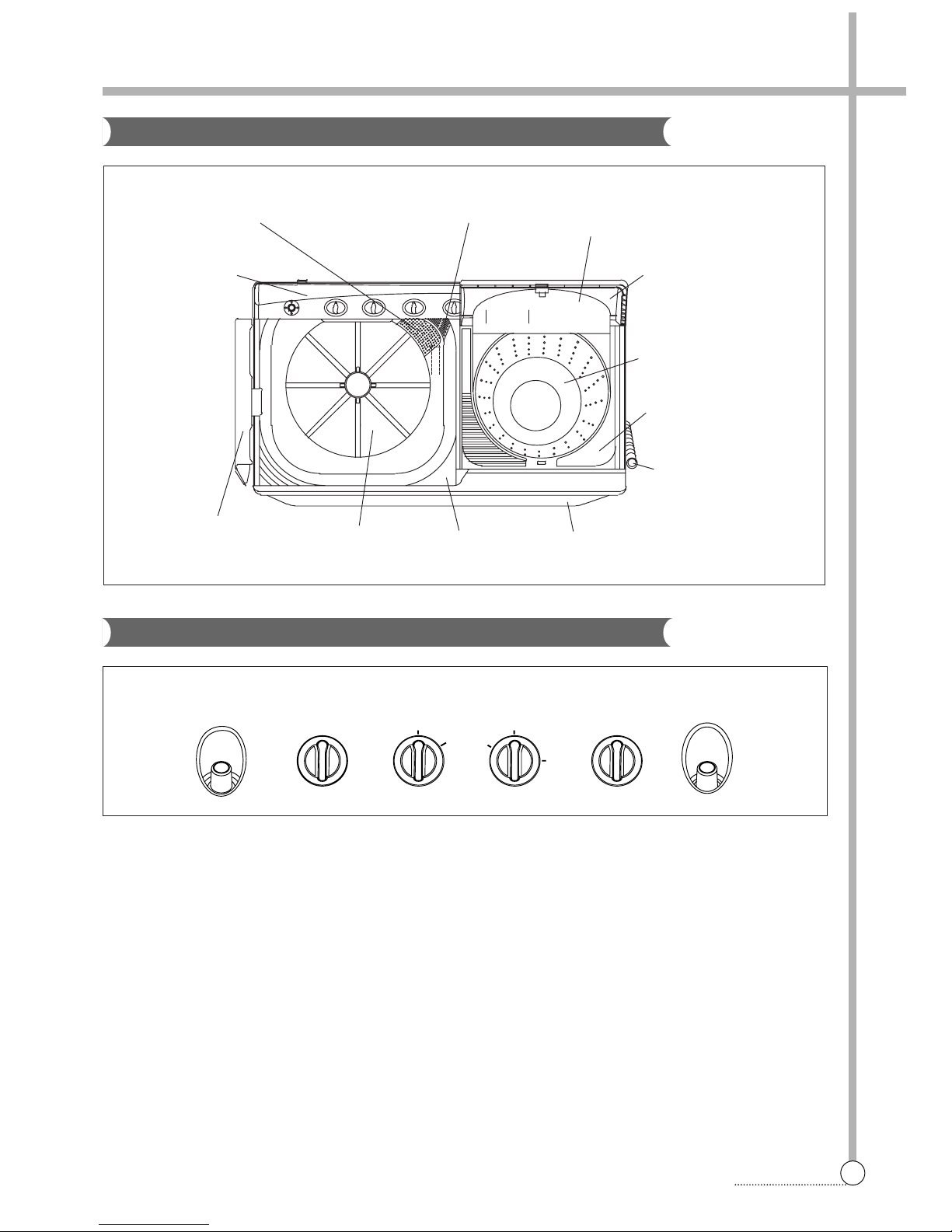
STRUCTURE
Structure Of The Wash Machine
F unctions of Control Panel
11
WATER INLET - WASH
Connect inlet hose to supply water in the wash tub.
22
WASH TIMER
Use to select the desired time for washing or rinsing.
33
WASH ACTION
Use to select wash action. (“STRONG”, “NORMAL”)
44
LEVER SELECTOR
Select “WASH.RINSE” for washing or rinsing, and
“DRAIN” to drain the water. (In case pump model,
turn on the DRAIN PUMP.) “OFF to turn off the
DRAIN PUMP. (Only pump model)
55
SPIN TIMER
Used to select the desired time for spinning.
66
WATER INLET - SPIN
Connect inlet hose to supply water in the spin tub.
DRAIN STRAINER
COVER SAFETY
DOOR SPIN
BASKET SPIN
PLATE T
DRAIN HOSE
CABINET
TUB
PUL SATOR
DOOR WASH
PANEL B
GUIDE FILTER
WATER INLET
WASH TUB
WASH TIMER WASH ACTION
NORMAL WASH/RINSE
OFF
DRAIN
0
1
2
3
4
5
0
3
6
9
12
15
STRONG
VALVE
SELECTOR
SPIN TIMER WATER INLET
SPIN TUB
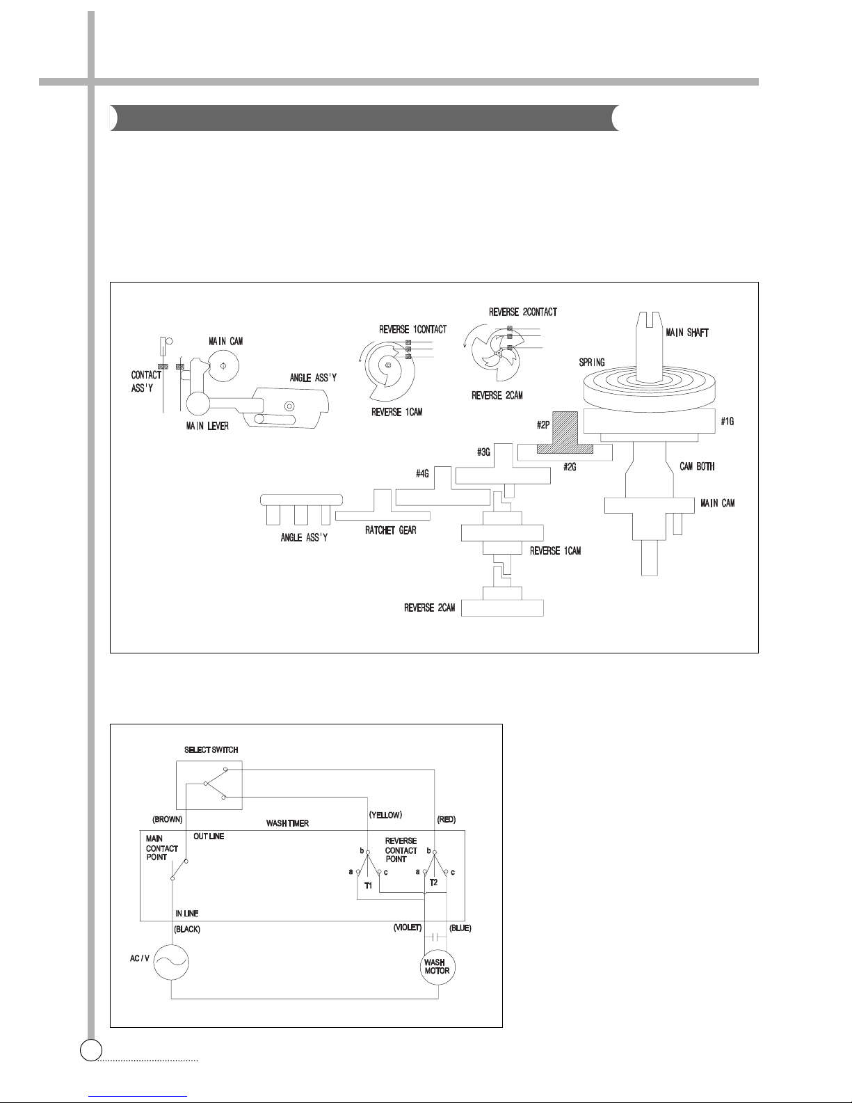
FUNCTION
The main switch remains ON during the washing time set by turning the timer knob.
At the same time, the internal switch T1 and T2 which provide power to WASH MOTOR alternately at assigned Intervals.
Select switch knob sets the wash type by means of controlling the interval of internal switch contact.
STRUCTURE AND PRINCIPLE OF ACTIVATION
3. PRINCIPLES OF OPERATION AND EXPLANATION OF FUNCTIONS
5
CONTROL PANEL
W ash Timer
CIRCUIT DIAGRAM
6
PROCEDURE
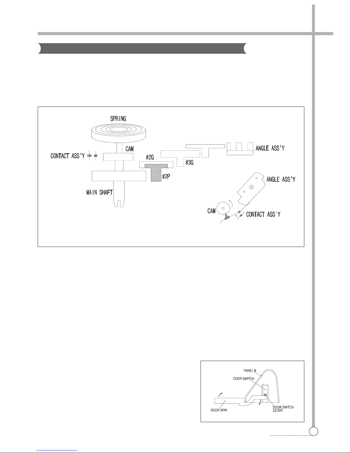
FUNCTION
The spin timer is the switch providing power to the SPIN MOTOR(DRAIN PUMP MOTOR) during the set spin dry
time, and is a spring-type time switch comes on upon turning and those contact points comes off after the set time.
STRUCTURE AND PRINCIPLE OF ACTIVATION
1) The main shaft turns due to the unwinding force when the spin timer is turned, the spring wound with that force
being delivered through each gear and the spring slowly unwinding at a speed finally controlled by the angle
assembly.
2) The contact point Turns ON and the assembly angle is set in motion which is in the CAM groove in the OFF
state, comes off the groove when the main shaft is turned to wind the spring. The contact point turns OFF,
return to CAM groove when the spring unwind completely.
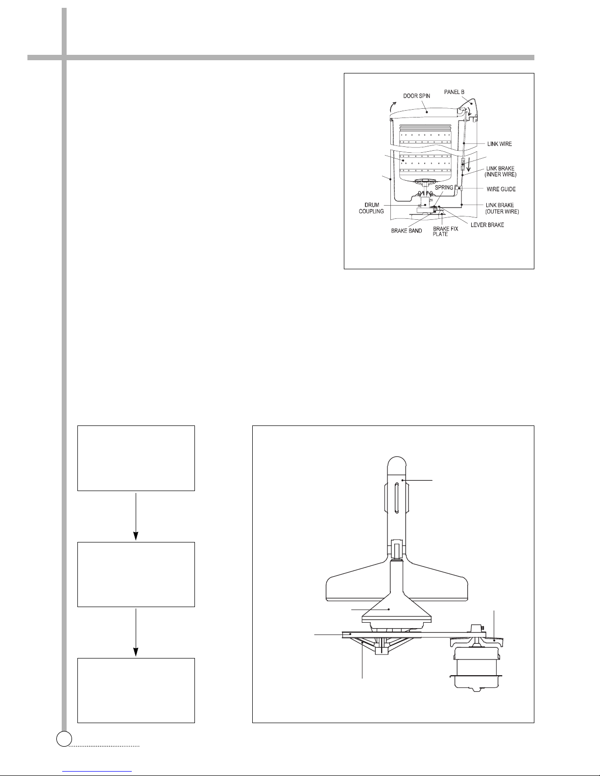
SAFETY DEVICE FOR BASKET SPIN
The BASKET SPIN is an apparatus which eliminates the water from the laundry through centrifugal separation
generated by rapid revolution(approximately 1,600rpm for 60Hz). Accordingly, there are a DOOR SWITCH to cut
off the power going into the DOOR SPIN is opened and a brake system to stop the rotating BASKET SPIN.
DOOR SWITCH (Option)
When the DOOR SPIN is opened during spinning, the DOOR
SWITCH LEVER which sites atop the DOOR SPIN falls off the
contact, and cuts off the power going into the SPIN MOTOR.
Spin Timer
7
PROCEDURE
BRAKE SYSTEM (Option)
When the DOOR SPIN is opened, LINK WIRE which connect
to DOOR SPIN loosens. And then the BRAKE BAND touches
the DRUM COUPLING assemply and stops the SPIN DRYER
as it is pulled by the SPRING in the BRAKE FIX PLATE
assembly.
BRAKE BAND GAP CONTROL METHOD
(Option)
The BAND BRAKE works best when the gap between it and
the DRUM COUPLING is about 2mm when the DOOR SPIN
is closed. The SPIN DRYER stops slowly if the gap between
the two is too narrow, the SPIN DRYER revolution is affected
and the PLATE CONTROL WIRE may be adjusted to main-
tain the BRAKE BAND gap adequately.
WASH DECELERATOR ASSEMBLY
The initial deceleration following the activation of the WASH MOTOR takes place through the PULLEY MOTOR
and PULLEY PULSATOR, and the secondary deceleration is done by the gear in the GEAR HOUSING which also
increeases their revolution strength. This revolution speed and strength is delivered to the PULSATOR, which is
then able to cause water current that is strong yet soft so that wash loads are not damaged.
PLATE
CO NTROL WIRE
BA
BASE
SKET SPI N
AGITATOR ASS’Y
PULLEY
MOTOR
PULLEY AGITATOR
V-BELT
GEAR HOUSING
MOTOR WASH
About 1,700rpm
M-Pully (4:1)
PULLEY PULSATOR
About 425rpm
AGITATOR
About 100rpm
G/H (4.18:1)
 Loading...