

DAEWOO DWF-760, DWF-761, DWF-762, DWF-810, DWF-811 Service Manual
...
Service Manual
Auto Washer
Model: DWF-760/761/762
DWF-810/811/812
DAEWOO ELECTRONICS CO., LTD.
http : //svc.dwe.co .kr Aug. 2002
✔
Caution
: In this Manual, some parts can be changed for improving, their
performance without notice in the parts list. So, if you need the
latest parts information,please refer to PPL(Parts Price List) in
Service Information Center (http://svc.dwe.co.kr).

AUTO WASHER AUTO WASHER AUTO WASHER AUTO WASHER AUTO WASHER AUTO WASHER AUTO WASHER AUTO WASHER AUTO WASHER AUTO
WASHER AUTO WASHER AUTO WASHER AUTO WASHER AUTO WASHER AUTO WASHER AUTO WASHER AUTO WASHER AUTO WASHER AUTO WASHER
AUTO WASHER AUTO WASHER AUTO WASHER AUTO WASHER AUTO WASHER AUTO WASHER AUTO WASHER AUTO WASHER AUTO WASHER AUTO
WASHER AUTO WASHER AUTO WASHER AUTO WASHER AUTO WASHER AUTO WASHER AUTO WASHER AUTO WASHER AUTO WASHER AUTO WASHER
AUTO WASHER AUTO WASHER AUTO WASHER AUTO WASHER AUTO WASHER AUTO WASHER AUTO WASHER AUTO WASHER AUTO WASHER AUTO
WASHER AUTO WASHER AUTO WASHER AUTO WASHER AUTO WASHER AUTO WASHER AUTO WASHER AUTO WASHER AUTO WASHER AUTO WASHER
AUTO WASHER AUTO WASHER AUTO WASHER AUTO WASHER AUTO WASHER AUTO WASHER AUTO WASHER AUTO WASHER AUTO WASHER AUTO
WASHER AUTO WASHER AUTO WASHER AUTO WASHER AUTO WASHER AUTO WASHER AUTO WASHER AUTO WASHER AUTO WASHER AUTO WASHER
WASHING MACHINE
CCoonntteennttss
1. SPECIFICATIONS................................................................................................................... 2
2. STRUCTURE OF THE WASHING MACHINE........................................................................ 3
3. FUNCTIONS OF THE CONTROL PANEL............................................................................. 4
4. DIRECTIONS FOR INSTALLATION AND USE
LOCATION OF WASHER................................................................................................................ 5
DRAIN SYSTEM.............................................................................................................................. 5
HOW TO CONNECT THE INLET HOSE........................................................................................ 6
HOW TO CLEAN THE FILTER....................................................................................................... 7
5. FEATURE AND TECHNICAL EXPLANATION
FEATURE OF THE WASHING MACHINE...................................................................................... 8
WATER CURRENT TO ADJUST THE UNBALANCED LO AD....................................................... 8
AUTOMATIC WATER SUPPLY SYSTEM .......................................................................................8
AUTOMATIC DRAINING TIME ADJUSTMENT.............................................................................. 9
SOFTENER DISPENSER............................................................................................................. 10
AUTOMATIC UNBALANCE ADJUSTMENT................................................................................. 11
CIRCULATING-WATER................................................................................................................. 11
LINT FILTER.................................................................................................................................. 12
RESIDUAL TIME DISPLAY...........................................................................................................12
DRAIN MOT OR............................................................................................................................. 12
GEAR MECHANISM ASS’Y ......................................................................................................... 13
PRINCIPLE OF BUBBLE GENERATOR...................................................................................... 13
FUNCTIONAL PRINCIPLE OF BUBBLE WASHING MACHINE ................................................. 14
6. DIRECTIONS FOR DISASSEMBLY AND ADJUSTMENT
GEAR MECHANISM ASS’Y REPLACEMENT............................................................................. 15
MOT OR SYNCHRONOUS AND VALVE REPLACEMENT.......................................................... 17
BRAKE ADJUSTMENT................................................................................................................. 17
7. THE REPAIR METHOD OF GEAR MECHANISM FOR CLUTCH SPRING PROBLEM
THE STRUCTURE OF GEAR MECHANISM............................................................................... 18
HOW TO CHECK THE CLUTCH SPRING PROBLEM................................................................ 19
THE PROCESS OF DISASSEMBLE............................................................................................ 20
THE PROCESS OF ASSEMBLE.................................................................................................. 22
8. TROUBLE SHOOTING GUIDE
CONCERNING WATER SUPPLY..................................................................................................24
CONCERNING WASHING........................................................................................................... 25
CONCERNING DRAINING........................................................................................................... 26
CONCERNING SPINNING........................................................................................................... 27
CONCERNING OPERATION.........................................................................................................28
9. PRESENTATION OF THE P.C.B ASS’Y ...............................................................................29
APPENDIX
WIRING DIAGRAM....................................................................................................................... 30
PARTS DIAGRAM & PARTS LIST................................................................................................ 34
CIRCUIT DIAGRAM...................................................................................................................... 43
1. SPECIFICATIONS
2
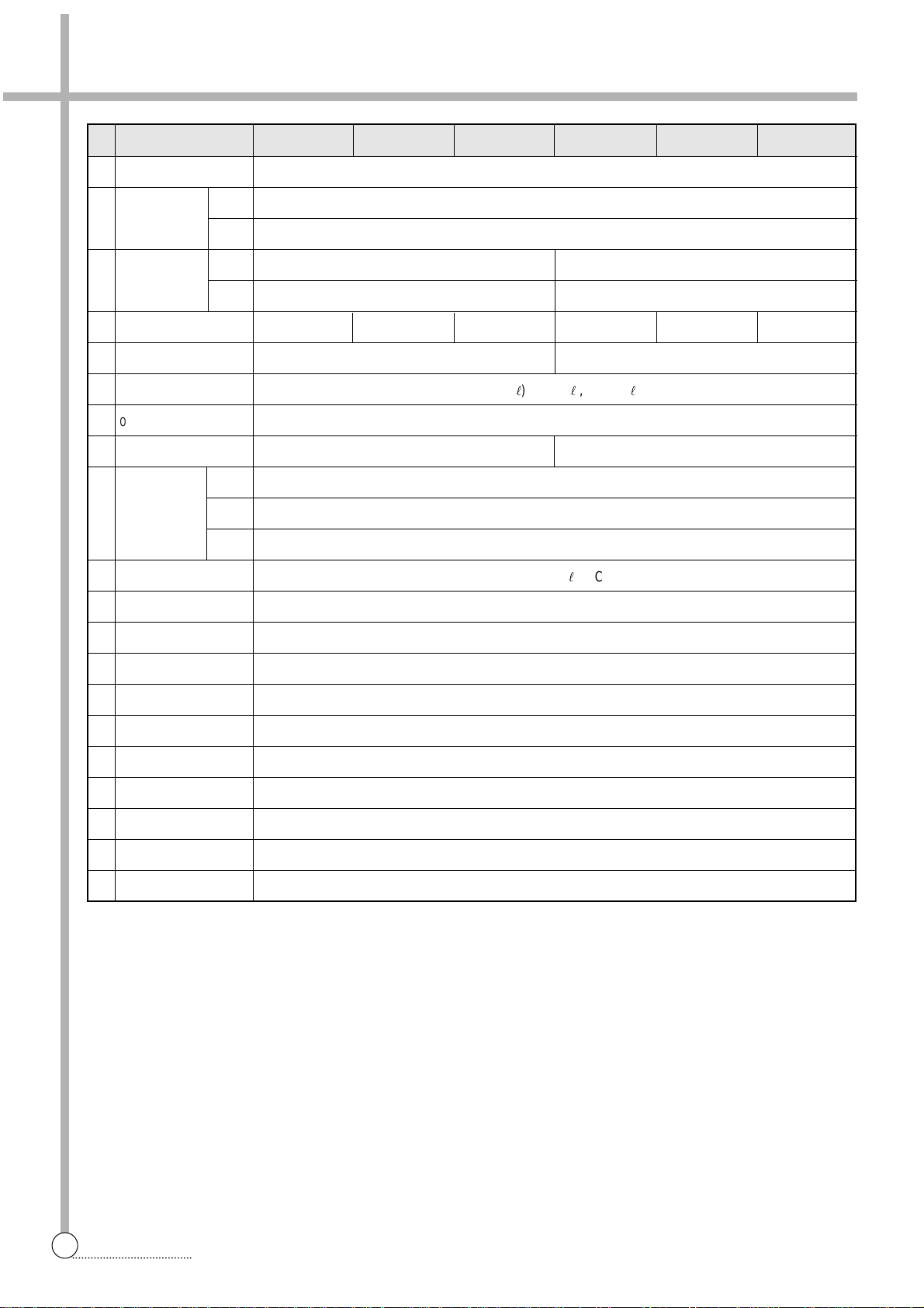
SPECIFICATIONS
NO. ITEM
1 POWER SOURCE AVAILABLE IN ALL LOCAL AC VOLTAGE
2
POWER
50Hz 240W(100V)/320W
CONSUMPTION
60Hz 280W(100V)/300W(110~127V) / 340W(220V)
3
MACHINE NET
WEIGHT
GROSS
4 DIMENSION (WXHXD)
5
MATERIAL OF INTERNAL TUB
PLASTIC STAINLESS STEEL
6
WATER LEVEL SELECTOR
HIGH(55l), MID(45l), LOW(31l)
7
OPERATING WATER PRESSURE
29kPa ~ 784kPa (0.3kgf/cm2~8kgf/cm2)
8
MAXIMUM MASS OF TEXTILE
5.5kg 6.0kg
REVOLUTION
WASH 125~145(50Hz), 130~150(60Hz)
9 SPIN 660~690(100V/50Hz), 680~730(50Hz), 780~810(100V/60Hz), 770~800(60Hz)
PER MINUTE
SUIT 50(50Hz), 60(60Hz)
10
WATER CONSUMPTION
APPROX. 130l/CYCLE
11
WATER LEVEL CONTROL
ELECTRONICAL SENSOR
12 ANTI NOISE PLATE OPTION
13
GEAR MECHANISM ASS’Y
SPUR GEAR
14 LINT FILTER O
15 SOFTENER INLET O
16 ALARM SIGNAL O
17 AUT O . WA TER SUPPLY O
18
FUNCTION FOR BUBBLE
OPTION
19
AUT O RE-FEED WA TER
O
20 AUT O PO WER OFF O
DWF-760 DWF-761 DWF-762 DWF-810 DWF-811 DWF-812
525X858X535 525X891X535 525X948X535 525X858X535 525X891X535 525X948X535
28kg/28.5kg(pump)
31.5kg/32kg(pump)
28.5kg/29kg(pump)
32kg/32.5kg(pump)
2. STRUCTURE OF THE WASHING MACHINE
3
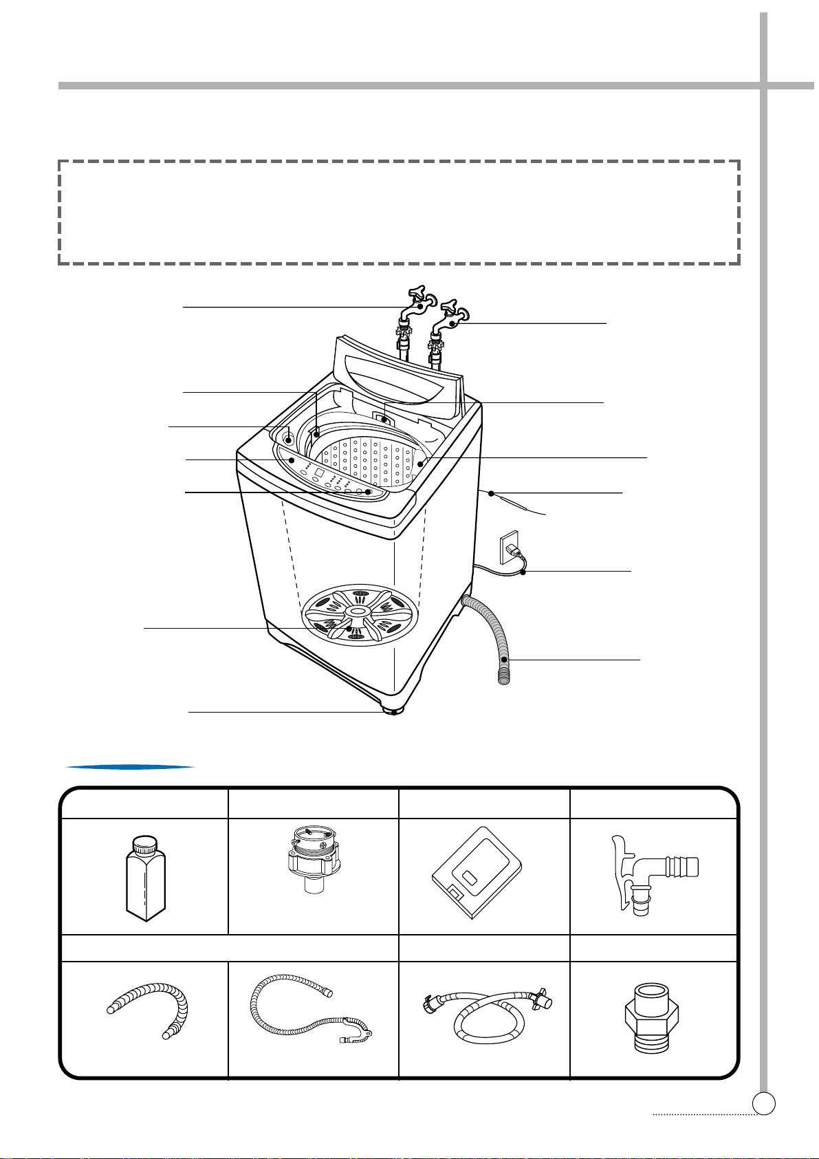
STRUCTURE
• GROUND WIRE
In case of 3-wire
power cord, ground
wire will not be
provided
• POWER CORD
• DRAIN HOSE
• LINT FILTER
• COLD WATER TAP
After using the washer,
close the water tap
• DETERGENT CASE
• ADJUSTABLE LEG
• SOFTENER INLET
• BLEACH INLET
• CONTROL PANEL
• POWER SWITCH
• PULSATOR
• HOT WATER TAP
After using the washer, close the water tap.
In case of the single valve model,
there is no hot water valve.
DRYTEN(OPTION) HOSE ADAPTER UNDER COVER(OPTION)
INLET HOSE(OPTION)
HOSE CONNECTOR(OPTION)
CONNECTOR INLET(OPTION)
Accessories
UP
The parts and features of your washer are illustrated on this page.
Become familiar with all parts and features before using your washer.
NOTE
• The drawing in this book may vary from your washer model. They are designed to show the different features of all models covered by this book, Your model may not include all features.
• Page references are included next to same features.
Refer to those pages for more inf ormation about the features.
DRAIN HOSE
In case of screw shaped inlet hoses
water tap adapters will not be provided.
NON PUMP MODEL PUMP MODEL
3. FUNCTIONS OF THE CONTROL PANEL
4
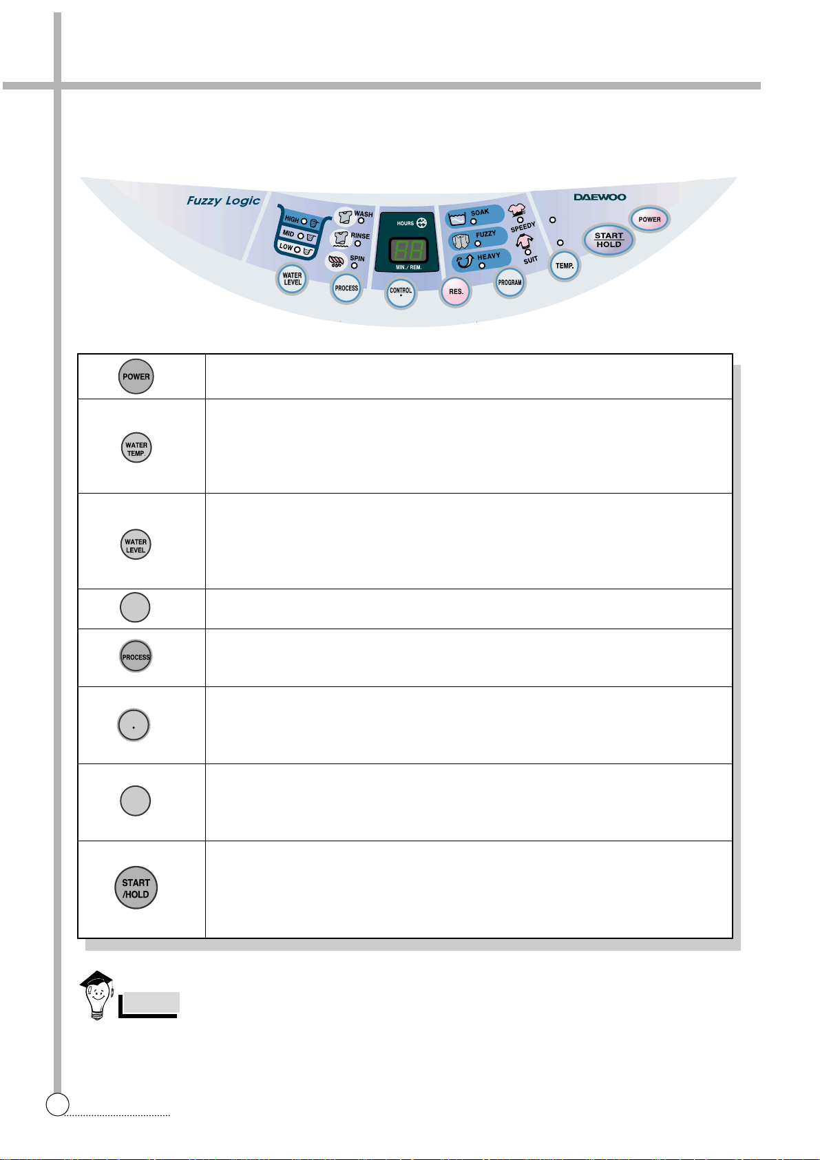
CONTROL PANEL
HOT
COLD
DWF-760M
ONLY SPIN
Control panel has micom sensor.
As the buttons are pressed, the lamps indicating the selection of your desired washing program will light up.
• If you open the Door(Lid) When wash and rinse processing, the PULSATOR is not working with
“LE” signal on the PCB and Buzzer alarm.
• And if close the Door(Lid), the remain process will be done continuously.
NOTES
• Press this switch to turn the power on or off.
• It can be used to choose water temperature to be supplied.
• As the button is pressed, water temperature will be repeated.
COLD
➔ COLD+HOT ➔HOT
• In case of the single valve model, there is no wash temperature selector function.
• It can be used to adjust amount of water according to the size of the load to be
washed.
• As the button is pressed, water level is selected by
MID ➔ HIGH ➔ LOW
• It can be used to pre-engage time for wash.
• It is the button for the partial process or the combination of each process (wash, rinse,
spin)
• If you want to change wash time, rinse times, spin time , y ou m ust press this b utton
after selection each process by the process button.
Also, this button can be used to spin only.
• It can be used to select the full-automatic program.
• As the button is pressed, program will be selected by f ollo wing order:
FUZZY ➔ FUZZY+SOAK ➔ HEAVY ➔ HEAVY+SOAK ➔ SPEEDY ➔SUIT(WOOL)
• Operation and temporary stop is repeated as it is pressed.
• When you want to change program in operation;
press the “START/HOLD” button ➔ Select the program that you want to change ➔
press the “START/HOLD” button again.
RES.
CONTROL
ONLY SPIN
PROGRAM
4. DIRECTIONS FOR INSTALLATION AND USE
5
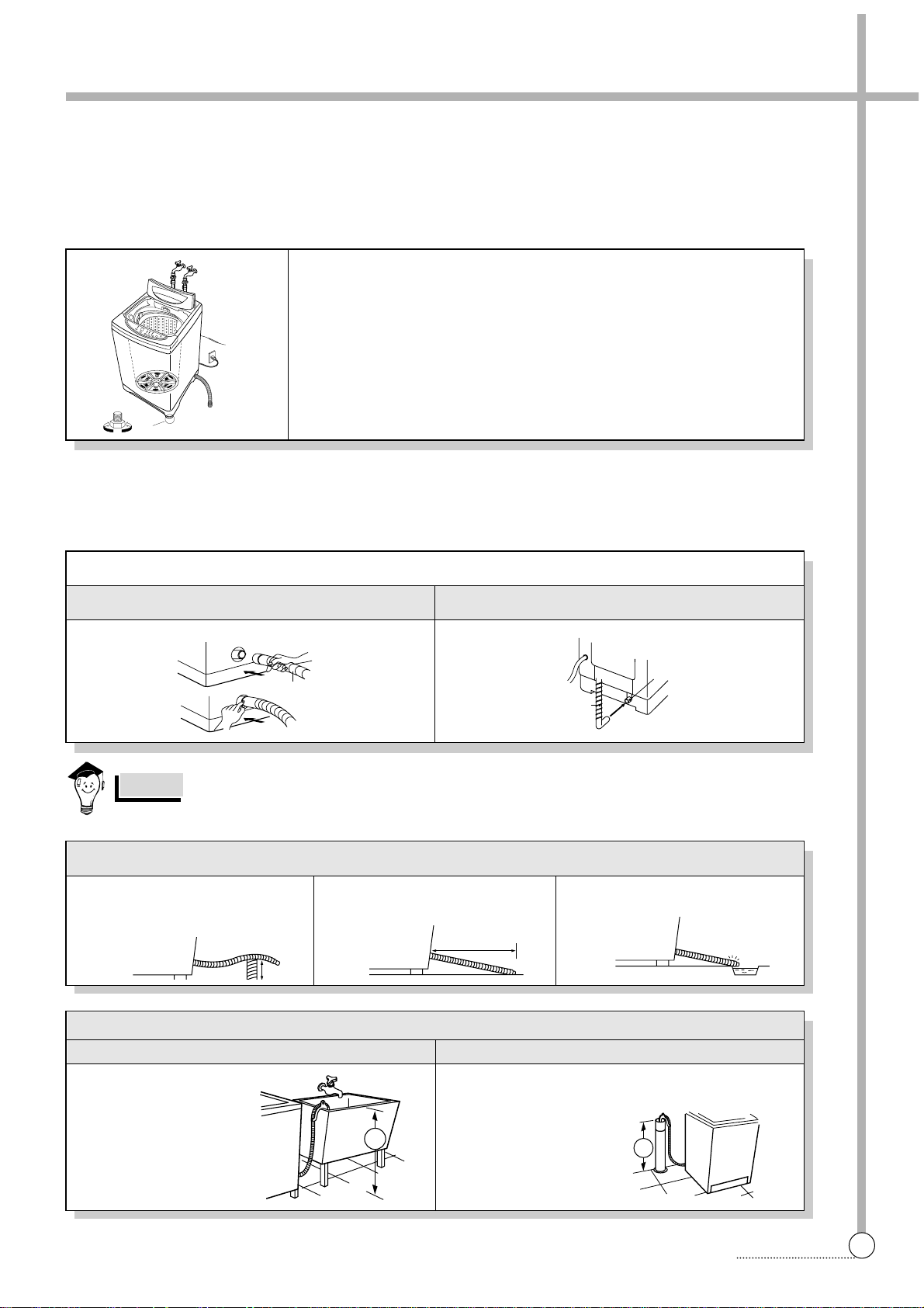
PROCEDURE
The opening must not be obstructed by carpeting when the washing machine is installed on a carpeted floor.
Location Of Washer
Check location where washer will be installed. Make sure you have everything necessary for correct installation.
Proper installation is your responsibility.
• Do not place or store your washer below 0˚C(32˚F) to a void any damage from freezing.
• Install the washer on the horizontal sold foor.
NOTES
If the washer is installed on an unsuitable floor, it could mak e considerab le
noise, vibrate and cause a malfunction.
If washer is not level, adjust the front leg(A) up or down for horizontal setting.
• Earthed electrical outlet(B) is required with 20cm of bottom back of
washer cabinet.
• Hot and cold water faucets (C) must be within 1M of the upper back of
the washer cabinet and provide water pressure 29kPa ~ 784kPa
(0.3kgf/cm
2
~ 8kgf/cm2)
Drain System
Never f orget to install drain hose before operating your washer.
The packing box is opened, there are a drain hose.
• Conect the drain hose to the drain outlet at the back side of the washer .
Non-Pump Model Pump Model
1 In case that it goes over a door sill.
Don’t let the height of the drain
hose exceed 20cm from the bottom
of washer.
2 In case of extending the drain hose.
Don’t let the total length exceed 3m.
3 Be careful that the end of the drain
hose is not immersed in water.
Non-Pump Model
• Top of tub must be at
least 86cm (34inches)
high and no higher than
130cm from bottom of
washer (A)
• Needs a 3cm minimum diameter standpipe with minimum
carry away capacity of 30liters per minute.
• Top of tub must be at
least 86cm(34inches)
high and no higher than
130cm from bottom of
washer (B)
Pump Model
Laundry tub drain system Standpipe drain system
C
UP DOWN
B
A
Drain hose
Drain Outlet
Drain hose
20Cm
3m
A
B
6
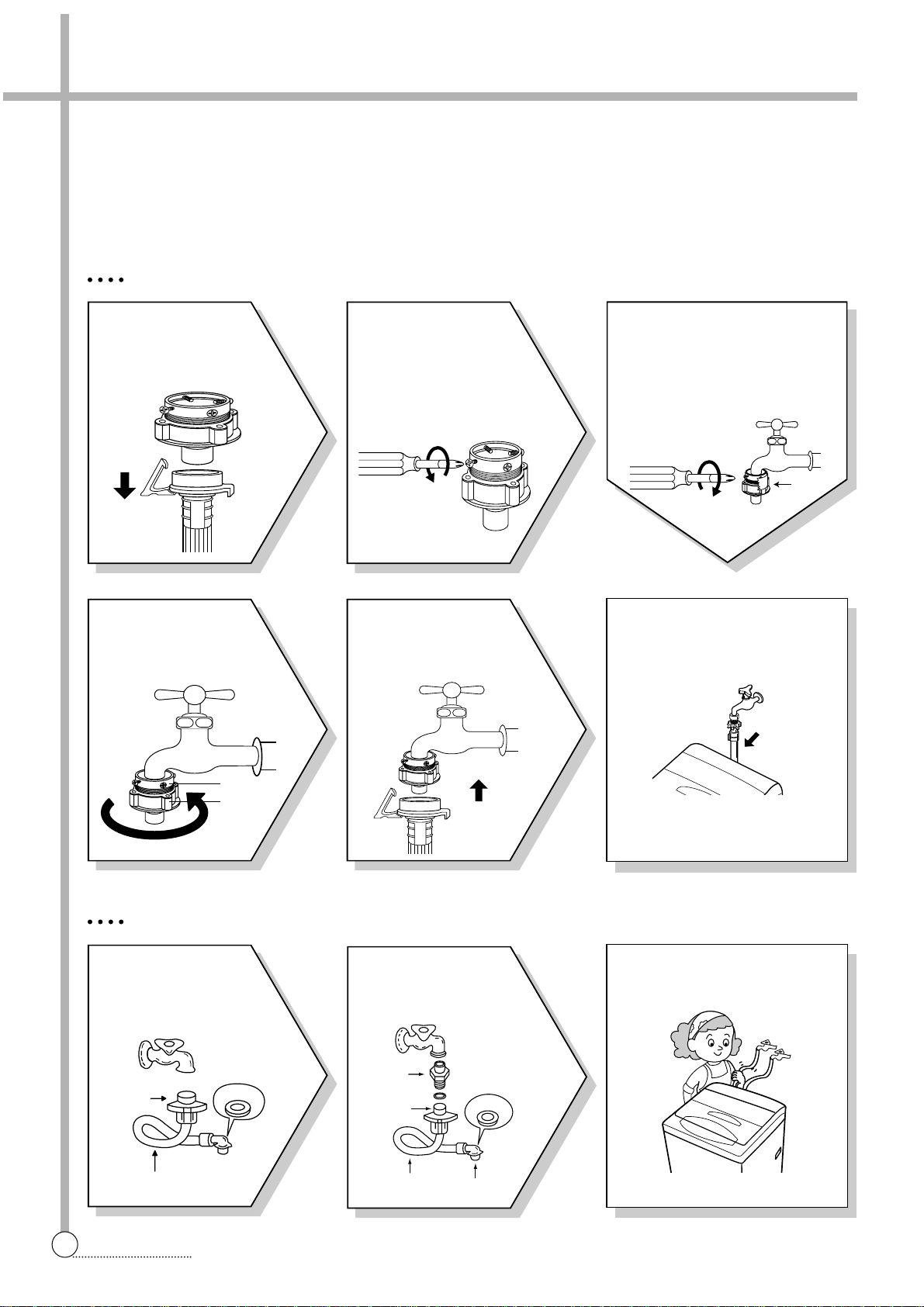
FOR ORDINARY TAP
6
Connect the inlet hose adapter
of the hose to the water inlet of
the washer by turning it clockwise to be fixed tightly.
• Please check the rubber packing
inside the inlet hose adapter of
the hose.
1
Pull down the collar
of the inlet hose to
separate it from the
water tap adapter.
2
Loosen the four
screws at the water
tap adapter, but don’t
loosen the screws until
they are separated from
the water tap adapter.
4
Remove the tape,
and screw connector
B into connect A tightly.
5
Connect the inlet
hose to the water tap
adapter by pulling down
the collar of the hose end.
3
Connect the water tap
adapter to the water tap and
tighten the four screws evenly
while pushing up the adapter
so that the rubber packing
can stick to the water tap
tightly.
How to Connect the Inlet Hose
Be careful not to mistake in supplying between the hot(maximum : 50˚C) and cold water.
In using only one water tap or in case of attached one water inlet valve, connect the inlet hose to the cold water inlet
valve.
Do not over tighten : this could cause damage to couplings.
FOR SCREW-SHAPED TAP
3
Insert the inlet hose adapter
into the water inlet of washer
and turn it to be fixed.
• Assert the packing in the inlet
1
Connect the inlet
hose to the water tap
by screwing the connector D tightly.
Inlet Hose
Connector D
Rubber
Packing
Connector C
TAPE
Connector B
Connector A
DIRECTIONS
← collar
2
Connect the connector-inlet supplied if
necessary.
Connector
Inlet
Rubber
Packing
Connector D
Connector C
Hose
7
CONNECTION
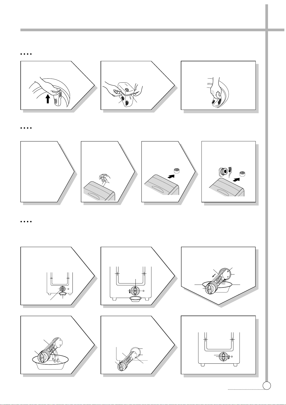
How To Clean The Filter
4
Remove the dirt
from the inlet filter
with a brush.
1
Pull the
power plug
out before
cleaning it.
2
Turn off the
water supply
to the washer
and separate
the inlet hose.
3
Pull the
inlet filter out.
CLEANING THE LINT FIL TER
CLEANING THE WATER INLET FIL TER
• Clean the filter when water leaks from the water inlet.
CLEANING THE DRAIN FIL TER
• In case of “U” shaped drain hose, this filter’s equipped at the back side of washer.
• This drain filter is to screen the foreign stuffs such as threads, coins, pins, b uttons etc ..
• If the drain filter is not cleaned at proper time (every 10 times of use), drain problem could be caused.
3
Return the filter as it was, and
insert the filter frame into the
slot.
1
Pull the Filter frame
upward.
2
Turn the lint filter
inside out, wash the
lint off with water.
1
Put down the
remained water in the
hose. And put a container
under the filter to collect
water.
2
Turn the cap counterclockwise.
3
Pull out the filter assembly off
the case of the main body.
6
Turn the cap clockwise tightly.
4
Clean the drain filter
removing the foreign
stuffs.
5
Put in the filter along the
guiding prominence of the
case. Please note the left
position of the filter adjusting
the groove to the guide rib.
FILTER
CONTAINER
CAP
SLIT
CASE
FILTER
CAP
CAP
FILTER
CAP
FILTER
CASE
GUIDE
RIB
SLIT
CAP
Filter Frame
Lint Filter
5. FEATURE AND TECHNICAL EXPLANATION
8
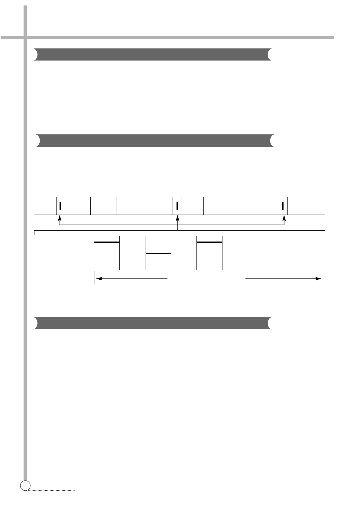
WASH DRAIN SPIN FILL RINSE 1 DRAIN SPIN FILL RINSE 2 DRAIN •••
MOTOR C.W
SINGAL C.C.W
TIME(SEC.) 0.3 0.3 0.3 0.3 0.3 0.3 •••••••
35 SEC. (About 30 Times)
Feature of the Washing Machine
1 The first air bubble w ashing system in the world.
2 Quiet washing through the innovational low-noise design.
3 The wash effectiveness is much more enhanced because of the air bubble washing system.
4 The laundry detergent dissolves well in water because of the air bubble w ashing system.
5 The adoption of the water currents to adjust the unbalanced load.
6 One-touch operation system.
Water Current to Adjust the Unbalanced Load
It is a function to prevent eccentricity of the clothes after wash by rotating pulsator C.W and C.C.W for 35
seconds.(But, the SUIT course have no operation of the water currents to adjust the unbalnced load.)
EFFECT
It reduces vibration and noise effectively while spinning.
WATER FLOW
Automatic Water Supply System
The water level would be lowered because the clothes absorbs water at the beginning of washing. Therefore, after 60
seconds, the operation is interrupted to check the water level, and then the water is supplied again until the selected
water level is reached.
CONVENIENCE
9
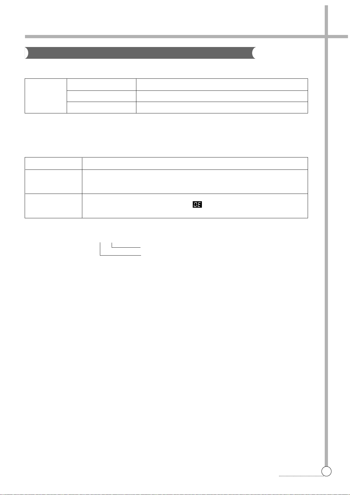
EXPLANATION
FUNCTIONAL PRINCIPLE
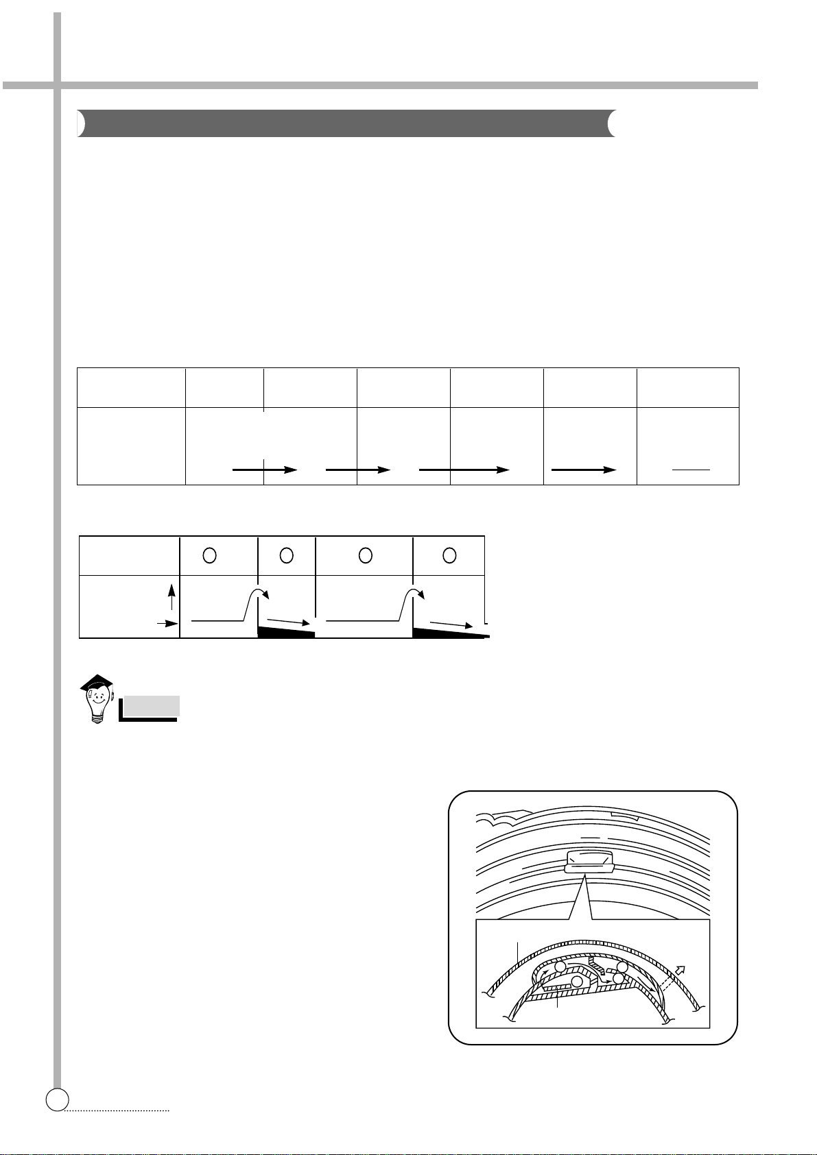
1 The micom can remember the time from the begining of drain to reset point when the pressure switch reaches to
“OFF” point
2 In case of continuous draining, residual drain time is determined by micom.
Draining time as a whole = D + 30
Residual drain time.
The time remembered by micom.
Draining
Good draining The washer begins spin process after drainage.
condition
Bad draining Draininig time is prolonged.
No draining Program is stopped and gives the alarm.
Drain Time Movement of the Program
Less than
Continue draining
10 minutes
More than
Program stops and gives the alarm with blinked on display lamp.
10 minutes
Automatic Drainning time Adjustment
This system adjusts the draining time automatically according to the draining condition.
10
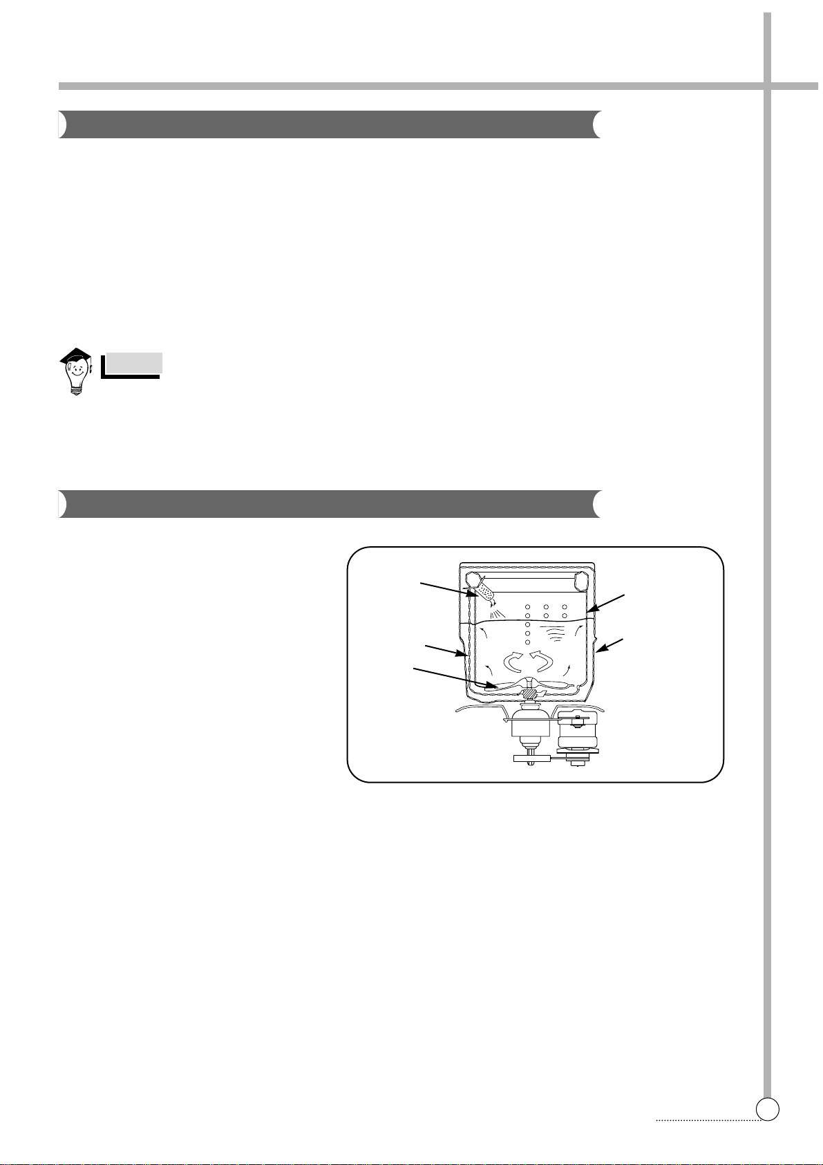
This is the device to dispense the softener automatically by centrifugal force.
This is installed inside the auto-balancer.
FUNCTIONAL PRINCIPLE
1 Softener stays in room (A) when poured into softener inlet.
2 Softener moves from (A) to (B) by centrifugal f orce during intermittent spin process.
3 Softener flows from (B) to (C) during rinse process next to intermittent spin.
4 Softener moves from (C) to (D) by centrigfugal f orce during second intermittent spin.
After spin process is finished, the softener is added into the tub through softener outlet.
FLOW OF THE SOFTENER
FLOW OF THE SOFTENER INSIDE OF THE BALANCER
HOW TO CHECK MOVEMENT
Pour a reasonable amount of “MILK” into softener dis-
penser and operate the washer with no load. In final
rinse cycle, make sure that the milk is added into the
tub through softener outlet.
A
B
C
D
Wash Intermittent Hold Intermittent Rinse Spin
Spin Spin
Normal Centrifugal Flow in Centrifugal Flow in
force force
Program (A) (B) (C) (D)
Room inside
the balancer
Centrifugal force
Flowing by weight
Balancer
Softener
outlet
Softener inlet
Softener Dispenser
Softener moves into the next room when r.p.m of the tub is more than 100 r.p.m.
NOTES
EXPLANATION
A
B
C D
11
EXPLANATION
Automatic Unbalance Adjustment
Circulating-Water
The alarm finished when you close the lid after opening it. Check the unbalance of the wash load and the
installation condition.
NOTES
Filter
Tub
Outer tub
Water
channel
Pulsator
This system is to prevent abnormal vibration during intermittent spin and spin process.
FUNCTIONAL PRINCIPLE
1 When the lid is closed, the safety switch contact is “ON” position.
2 In case that wash loads get uneven during spin, the outer tub hits the safety switch due to the serious vibration,
and the spin process is interrupted.
3 In case that P.C.B. ASS’Y gets “OFF” signal from the safety switch, spin process are stopped and rinse process is
started automatically by P.C.B. ASS’Y.
4 If the safety s witch is operated due to the unbalance of the tub, the program is stopped and the alarm is given.
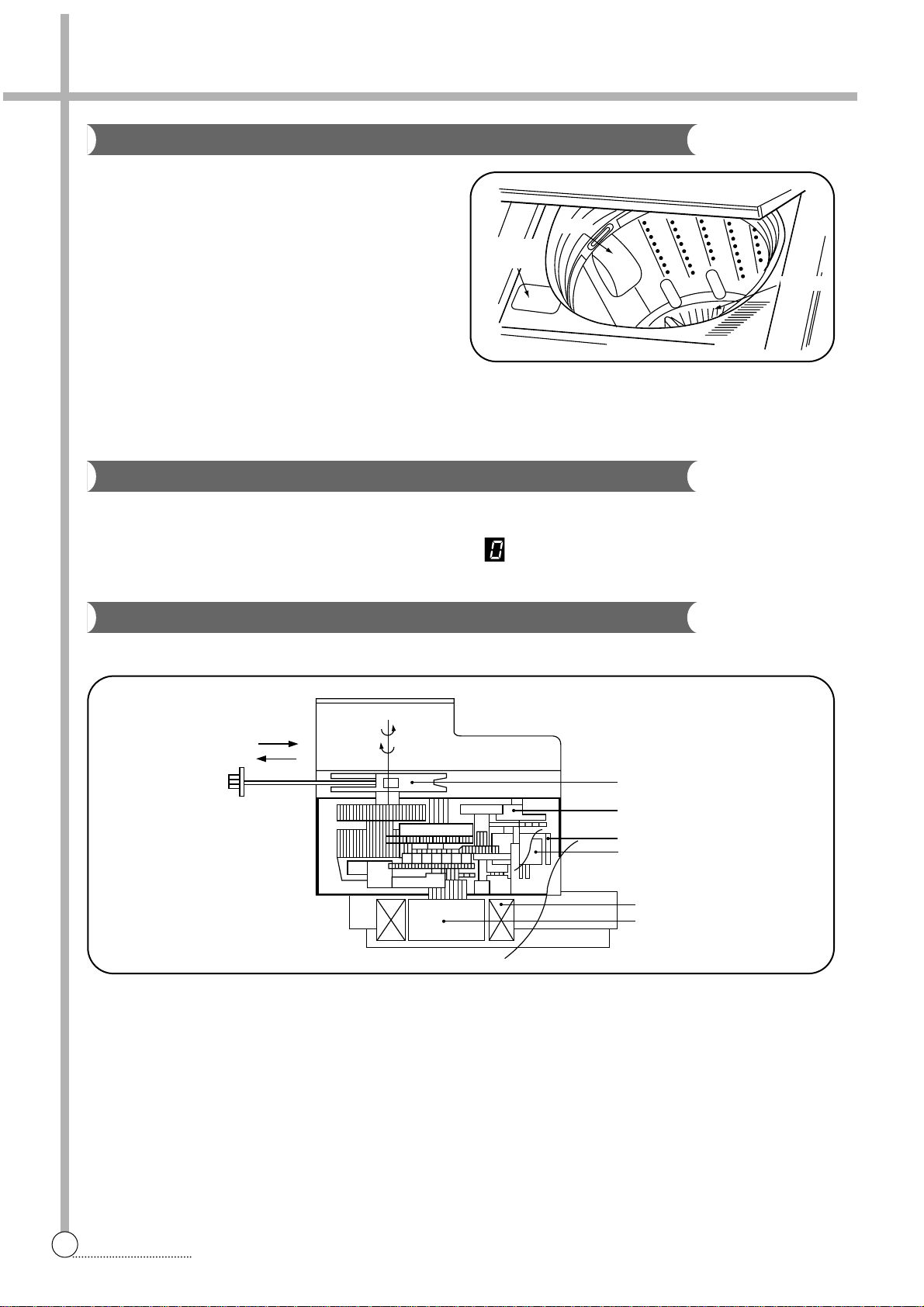
CIRCULATING-WATER
The washing and rinsing effects have been
improved by adopting the water system in
which water in the tub is circulated in a
designed pattern.
When the pulsator rotates during the washing
or rinsing process, the water below the pulsator vanes creates a water currents as shown
in figure.
The water is then discharged from the upper
part of the tub through the water channel.
About 40 L/min. water is circulated at the ‘high’
water level, standard wash load and standard
water currents.
12
Much lint may be obtained according to the kind of
clothes to be washed and some of the lint may also
sticks to the clothes.
To minimize this possibility a lint filter is provided on
the upper part of the tub to filter the wash water as it
is discharged from the water channel. It is good to
use the lint filter during washing.
HOW TO REPLACE LINT FILTER
1 Pull the filter frame upward.
2 Turn the lint filter inside out, and wash the lint off with water.
3 Return the filter as it was, and fix the filter frame to the slot.
When the START/HOLD button is pressed, the residual time (min.) is displayed on the time indicator, and it will be
counted down according to process.
When operation is finished, the TIME INDICATOR will light up .
STRUCTURE
FUNCTIONAL PRINCIPLE
1 When the DRAIN MOTOR connected to the power source, the DRAIN MOTOR rotates with 900 r.p.m and
revolv es the pulle y by gear assembly for reducing.
2 When the pulley is rotated, the pulley winds the wire to open the drain valve.
3 Therefore, rotation of pulle y changed to the linear moving of wire .
4 The wire pulls the brake lever of Gear Mechanism Ass’y within 5 seconds.
5 After the wire pulled, gear assembly is separated from motor and condition of pulling is held by operation of the
lever.
6 When the power is turned off, the drain valve is closed because the wire returns to original position.
Bleach Inlet
Filter
Pulsator
Pull
Loosen
Pulley
Lever
Inductive ring
Magnet
Coil of motor
Magnet of motor
Lint Filter
Residual Time Display
Drain Motor
Bleach
Inlet
Filter
Pulsator
EXPLANATION
13
EXPLANATION
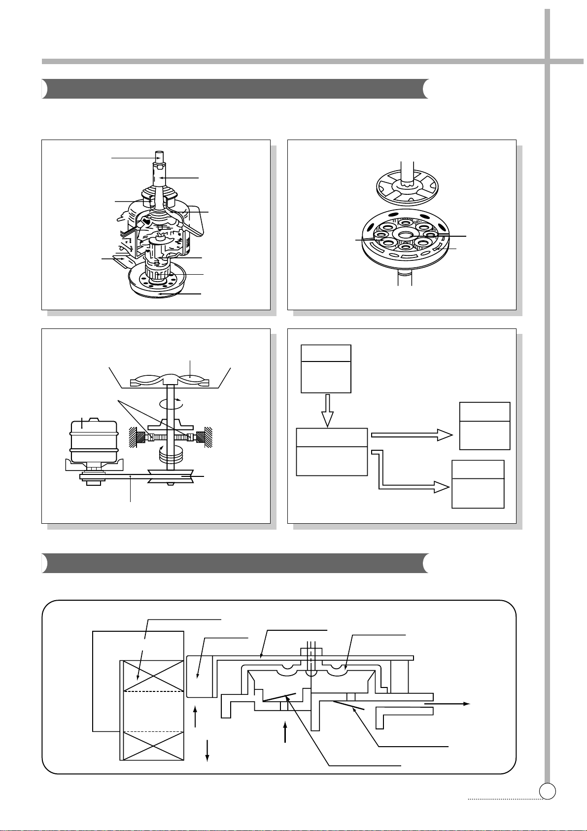
The proper water currents is made by the rotation of pulsator at a low speed to prevent the damage to the small sized
clothes.
STRUCTURE
Pulsator shaft
One way clutch
bearing
Brake lev er
Spin shaft
Gear unit as
Clutch spring
Clutch boss
Gear pulley
Planetary gear
Sun gear
Internal gear
Pulsator
1 revolution
5.2 revolutions
Gear pulley
V -belt
Gear unit as
Motor
Motor
1490 r.p.m
(50Hz)
Gear Unit as
Directly
Tub
720 r.p .m
Pulsator
138 r.p .m
Gear Pulley
720 r.p .m
Bobbin & coil
Magnet
Armature
Bellows
Air out hole
Protector A
Protector B
Air in hole
Air
Air
Trans core
Gear Mechanism Ass’y
Principle of Bubble Generator
 Loading...