

DAEWOO DWF-7560, DWF-7590, DWF-8060, DWF-8090 Service Manual
DAEWOO ELECTRONICS CO., LTD.
Service Manual
DWF-7560/7590 series
DWF-8060/8090 series
Full-Auto Electric Washing Machine

1
TABLE OF CONTENTS
1. SPECIFICATIONS.....................................................................................................................................................................2
2. FEATURE AND TECHNICAL EXPLANATION...................................................................................................................... 3
CONTROL SYSTEM FOR AUTO COURSE............................................................................................................................. 3
CONTROL SYSTEM FOR WOOL WASH ................................................................................................................................ 3
CONTROL SYSTEM FOR WOOL SPIN....................................................................................................................................4
WATER FLOW TO ADJUST THE UNBALANCED LOAD......................................................................................................... 4
FUNCTION FOR SOAK WASH..................................................................................................................................................4
AUTOMATIC WATER SUPPLY SYSTEM ON BLANKET WASH............................................................................................ 5
WATER FLOW ON STRONG WASH.........................................................................................................................................5
PULSATOR SYSTEM.................................................................................................................................................................5
AUTOMATIC DRAINING TIME ADJUSTMENT ........................................................................................................................6
SOFTENER DISPENSER............................................................................................................................................................ 7
AUTOMATIC UNBALANCE ADJUSTMENT............................................................................................................................. 8
CIRCULATING-WATER COURSE AND LINT FILTER..............................................................................................................8
AUTOMATIC POWER OFF ........................................................................................................................................................9
RESIDUAL TIME DISPLAY.........................................................................................................................................................9
DRAIN MOTOR........................................................................................................................................................................... 9
WATER LEVEL SWITCH.............................................................................................................................................................9
GEAR MECHANISM ASS'Y.....................................................................................................................................................10
SAFETY DEVICE FOR MOTOR...............................................................................................................................................10
PRINCIPLE OF BUBBLE GENERATOR..................................................................................................................................10
FUNCTIONAL PRINCIPLE OF BUBBLE WASHING MACHINE............................................................................................ 11
3. STRUCTURE OF WASHING MACHINE..............................................................................................................................12
STRUCTURE OF WASHING MACHINE.................................................................................................................................12
FUNCTION OF CONTROL PANEL.......................................................................................................................................... 13
4. INSTALLATION INSTRUCTIONS.........................................................................................................................................14
HOW TO INSTALL OF THE WASHING MACHINE................................................................................................................14
HOW TO CONNECT THE INLET HOSE..................................................................................................................................16
HOW TO REROUTE THE DRAIN HOSE.................................................................................................................................17
HOW TO INSTALL THE DRAIN HOSE....................................................................................................................................18
HOW TO CLEAN THE DRAIN FILTER.....................................................................................................................................19
5. OPERATING INSTRUCTIONS.............................................................................................................................................. 20
PROCEDURE OF FULL-AUTOMATIC WASHING.................................................................................................................20
PARTIAL SELECTIONS AMONG WASH, RINSE AND SPIN ................................................................................................22
6. PROGRESS CHART...............................................................................................................................................................24
7. HOW TO CHECK THE P.C.B. ASS'Y................................................................................................................................... 28
8. WIRING DIAGRAM................................................................................................................................................................. 29
9. DIRECTIONS FOR DISASSEMBLY AND ADJUSTMENT.................................................................................................32
GEAR MECHANISM ASS'Y REPLACEMENT........................................................................................................................32
DRAIN MOTOR VALVE REPLACEMENT................................................................................................................................ 33
BRAKE ADJUSTMENT............................................................................................................................................................. 33
10. EXPLODED VIEW AND PART LIST......................................................................................................................................34
EXPLODE VIEW........................................................................................................................................................................ 34
PARTS LIST...............................................................................................................................................................................37
11. TROUBLE SHOOTING GUIDE ..............................................................................................................................................41
CONCERNING WATER SUPPLY............................................................................................................................................41
CONCERNING WASHING.......................................................................................................................................................42
CONCERNING DRAINING.......................................................................................................................................................43
CONCERNING SPINNING.......................................................................................................................................................44
CONCERNING OPERATIONS.................................................................................................................................................45
CONCERNING ERROR MESSAGE........................................................................................................................................46
2
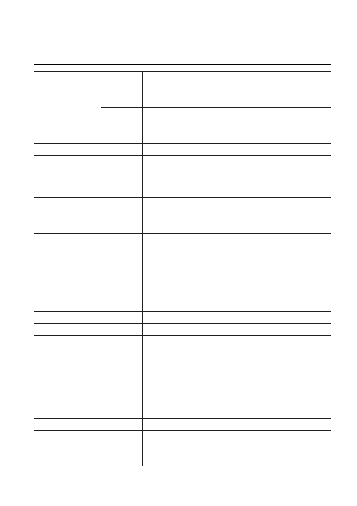
1. SPECIFICATIONS
NO ITEM SPECIFICATIONS
1 POWER SOURCE Available in All Local AC Voltage and Frequency
2 POWER DWF-7560/90 370W (50Hz), 460W (60Hz)
CONSUMPTION DWF-8060/90 400W (50Hz), 480W (60Hz)
3 MACHINE DWF-7560/90 NON PUMP: NET; 48kg, GROSS; 52kg PUMP: NET; 49kg, GROSS; 53kg
WEIGHT DWF-8060/90 NON PUMP: NET; 49kg, GROSS; 53kg PUMP: NET; 50kg, GROSS; 54kg
4 DIMENSION (WXHXD) 650X1005X650 mm
5 WASHING COURSE Full Automatic 6 Courses:
DRY; FUZZY, DRY, SILK, SPEED, STRONG, BLANKET
NON DRY; FUZZY, WOOL, SPEED, STRONG, BLANKET, NIGHT
and MEMORY Course
6 WATER CONSUMPTION 259 ` (7.5kg), 265 ` (8.0kg)
7 WATER LEVEL DWF-7570/90 HIGH (80 `), MIDDLE (68 `), LOW (55 `), SMALL (42 `), E.SMALL (32 `)
SELECTOR DWF-8060/90 HIGH (82 `), MIDDLE (70 `), LOW (57`), SMALL (43 `), E.SMALL (32 `)
8 OPERATING WATER PRESSURE 0.3~8kg/cm
2
(2.9~78.4N/cm2)
9 REVOLUTION PER MINUTE SPIN: 680rpm, WASH: 130rpm (50Hz)
WOOL WASH: 70rpm
SPIN: 780rpm, WASH: 150rpm (60 Hz)
10 PULSATOR 6 WINGS (ø 376mm)
11 WATER LEVEL CONTROL ELECTRONICAL SENSOR
12 OUTER CABINET PLASTIC
13 ANTI-NOISE PLATE O
14 GEAR MECHANISM ASSY HELICAL GEAR FOR LOW NOISE
15 LINT FILTER O
16 SOFTENER DISPENSOR O
17 AUTO. LOAD SENSING O
18 AUTO. POWER OFF O
19 FUNCTION FOR SOAK WASH O
20 ALARM SIGNAL O
21 RESIDUAL TIME DISPLAY O
22 AUTO. RE-FEED WATER O
23 NEW WATER FLOW WATER FLOW FOR ADJUSTING THE UNBALANCED LOAD
24 TRANSPARENT WINDOW O
25 FUNCTION FOR BUBBLE O
26
DWF-7560/90 7.5kg
DWF-8060/90 8.0kg
MAXIMUM
MASS of
TEXTILE
CONTROL SYSTEM FOR AUTO COURSE
FUNCTION PRINCIPLE OF SENSING
1) Sensing the wave width of two ports of capacitor.
2) Choosing the 'A~D' course according to the wave width.
3) Setting up the most suitable time to wash, rinse and spin by the judgement.
SENSING TIME
Sense the wave width for 28 seconds from start of washing.
OPERATING PROCESS ACCORDING TO THE WASHING CAPACITY
CONTROL SYSTEM FOR WOOL WASH
R.P.M of pulsator become half of normal wash by signal of P.C.B. Ass'y.
INPUT WAVE FORM OF MOTOR ON WOOL WASH
PROCESS OF WOOL WASH
When the DRY WOOL COURSE is selected, process shall be set up as below table automatically.
NOTE:
You can't change the water temperature because the P.C.B. ASS'Y set up the 'COLD TEMP' automatically at the
same time you select the 'WOOL COURSE'.
DRY/WOOL WASH
SILK WASH
[Only DRY series]
4sec ON 5sec OFF 4sec ON 5sec OFF
(C.W) (C.W)
3
2. FEATURE AND TECHNICAL EXPLANATION
3sec ON 5sec OFF 3sec ON 5sec OFF
(C.W) (C.W)
COURSE
WASHING WATER WASH TIMES OF SPIN
CAPACITY LEVEL TIME RINSE TIME
A 0~2.0 Kg E.Low 6 min 2 3 min
B 1.0~3.0 Kg Low 9 min 2 4 min
C 2.0~4.0 Kg MIDDLE 12 min 2 5 min
D Above 3.0 Kg High 15 min 2 5 min
(LOAD TO BE WATER WASH TIMES OF SPIN WASH
WASHED) LEVEL TIME RINSE TIME TEMP.
(Below 2 Kg) MIDDLE 6 min 2 30 sec COLD
CONTROL SYSTEM FOR WOOL SPIN
It is a function to prevent the deformation of WOOL.
PROGRESS CHART ON WOOL SPIN
WATER FLOW TO ADJUST THE UNBALANCED LOAD
It is a function to prevent eccentricity of the clothes after wash by rotating pulsator C.W and C.C.W for 20 seconds.
EFFECT
Reduce vibration and noise effectively while spinning.
WATER FLOW
FUNCTION FOR SOAK WASH
DISPLAY THE REMAINING TIME
When the SOAK WASH is selected, the total wash time will increase by 40 minutes.
PROGRESS
NOTE: "I" Mark shows the water flow to adjust the unbalanced laod.
4
R.P.M.
ON-OFF
TIME
OF
MOTOR
(sec)
WOOL
NORMAL
4
4
3
3
4
4
3
3
3
3
2
2
27474
BALANCE SPIN NORMAL SPIN
NORMAL
WOOL
WASH I DRAIN SPIN FILL RINSE 1 I DRAIN SPIN FILL RINSE 2 I DRAIN ...
SIGNAL
C.W
C.C.W
TIME (sec) 0.3 0.5 0.3 0.5 0.3 0.5 .........
20 sec (About 13 Cycles)
FILL WASH STOP WASH STOP WASH STOP
• 2min I 12min 1min I 12min 1min I 12min
SOAK PROCESS MAIN PROCESS
40 Minutes

AUTOMA TIC W ATER SUPPLY SYSTEM ON BLANKET WASH
The water level would be lowered because the blanket absorbs water at the beginning of washing.
Therefore, after 30 seconds, the operation is interrupted to check the water level, and then the water is supplied again until it
is reached at the selected level.
WATER FLOW ON STRONG WASH
It washes cleanly the heavily stained clothes such as working-clothes, climbing-clothes and blue-jean by using this strong
water currents as shown below.
WATER FLOW
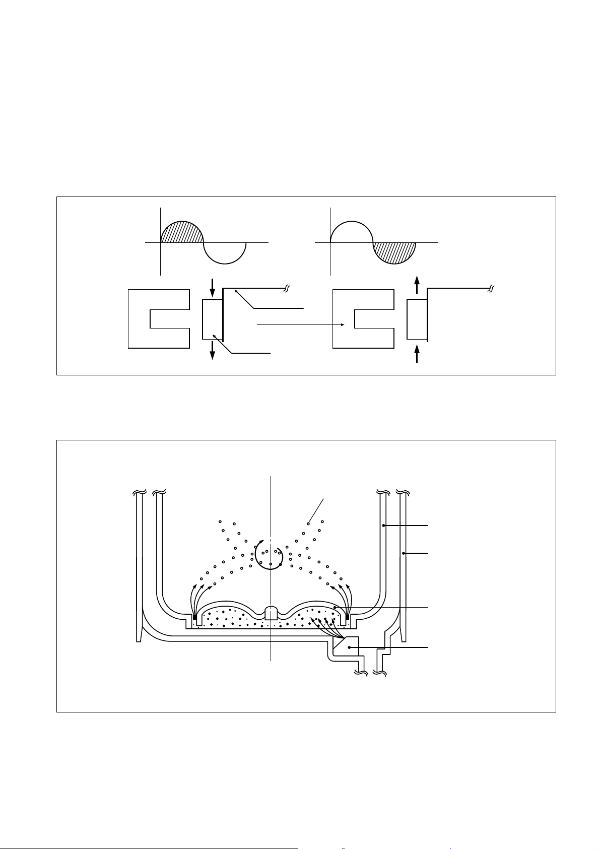
PULSA TOR SYSTEM
When the new shaped pulsator is rotated C.W or C.C.W at a high speed, it makes the 'heart-shaped' water currents as
shown below.
5
C.C.W
C.W
TIME (sec) 0.8 0.5 0.8 0.5 0.8 0.5 0.8 0.5 0.8 0.5 0.8 0.5 0.8 0.5 0.8 0.5 3.2 0.8 3.2 0.8
SIGNAL
OF
MOTOR
1 CYCLE
Rotate
B
AA
C
WATER FLOW
A Water is pushed out by rotation of
the pulsator.
B Water is pulled down by rotation
of the pulsator.
C Water flow is generated by
rotation of the pulsator.
6
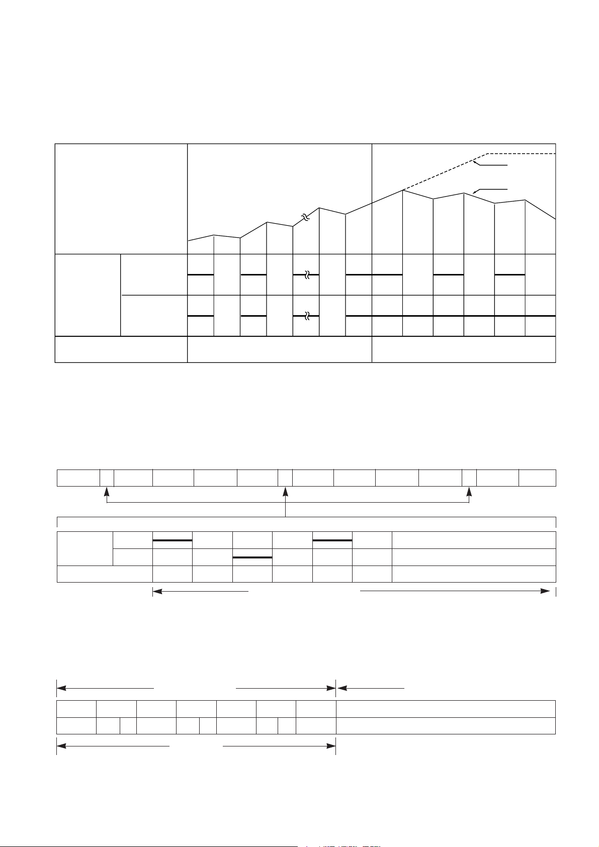
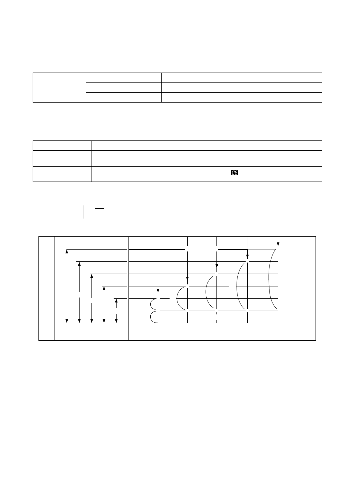
AUTOMA TIC DRAINING TIME ADJUSTMENT
This system set a drain time automatically depending on condition of draining.
FUNCTIONAL PRINCIPLE
1. The micom can remember the time from the beginning of drain to reset point when the pressure switch reaches to "OFF"
point.
2. In case of continuous draining, residual drain time is determined by micom.
Total drain time = D + 60
(T sec) Time of remaining drain process.
Count time of P.C.B. ASS'Y.
Good draining The washer begins spin process after drainage.
Bad draining Draining time is prolonged.
No draining Program is stopped and gives the alarm.
Draining
condition
Drain Time Movement of the program
Less than
Continue draining.
5 minutes
More than
Program are stopped and give an alarm with twinkle the " " on display lamp.
5 minutes
DRAINING TIME
T5
TRIP POINTS
*
T4
T3
T2
T1
D1
60
E. SMALL
D2
*
*
SMALL LOW MIDDLE
D3
*
RESET POINTS
(mm)
*
400
*
*
D4
*
D5
*
340
WATER LEVEL
280
220
170
60
0
HIGH
T1=D1+60 (sec) T2=D2+60 (sec) T3=D3+60 (sec)
T4=D4+60 (sec) T5=D5+60 (sec)
SOFTENER DISPENSER
This is the device to dispense the softener automatically by centrifugal force.
This is installed inside the auto-balancer.
FUNCTIONAL PRINCIPLE
1. Softener stays in room (A) when pour the softener to softener inlet.
2. Softener move (A) to (B) by centrifugal force during intermediate spin process.
3. Softener flow (B) to (C) during rinse process next of intermediate spin.
4. Softener move (C) to (D) by centrifugal force during second intermediate spin.
And after finish spin process, softener drop between tub and outer tub ass'y from softener outlet.
FLOW OF THE SOFTENER
FLOW OF THE SOFTENER INSIDE OF THE BALANCE
NOTE: Softener moves into next room when r.p.m of the tub is more than 100 r.p.m.
HOW TO CHECK MOVEMENT
Pour a reasonable amount of "MILK" into softener dispenser
and operate the washer with no load.
In final rinse cycle, make sure than the milk is added into the
tub through softener outlet.
7
Balancer
Softener inlet
Softener outlet
A
C
D
B
Wash intermediate Hold intermediate Rinse Spin
Spin Spin
Normal Centrifugal force Flow by Centrifugal force Flow by
weight weight
Course
(A) (B) (C) (D)
Room inside
ABCD
the balancer
Flow by
Centrifugal
force
8
AUTOMA TIC UNBALANCE ADJUSTMENT
This system is to prevent abnormal vibration during intermittent spin and spin process.
FUNCTIONAL PRINCIPLE
1. When the lid is closed, the safety switch contact is
"ON" position.
2. In case that wash loads get uneven during spin, the
outer tub hits the safety switch due to the serious
vibration, and the spin process is interrupted.
3. In case that P.C.B. ASS'Y gets "OFF" signal from the
safety switch, spin process are stopped and rinse
process is started automatically by P.C.B. ASS'Y.
4. If the safety switch is operated due to the unbalance
of the tub, the program is stopped and the alarm is
given.
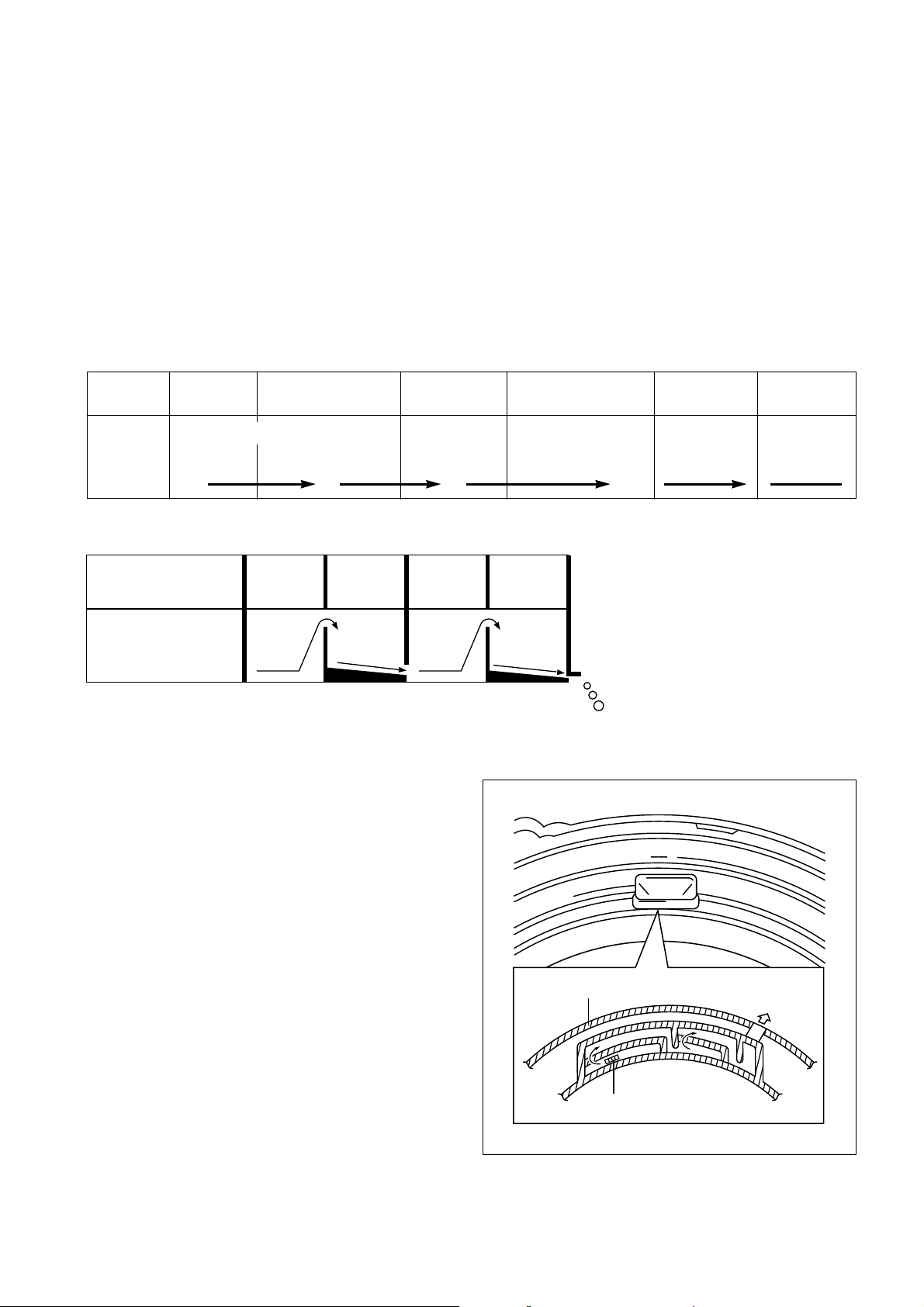
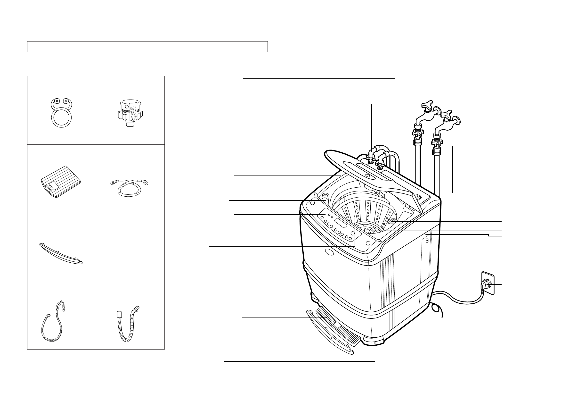
CIRCULA TING-W ATER COURSE AND LINT FILTER
CIRCULATING-WATER
The washing and rinsing effects have been improved by adopting
the water system in which water in the tub is circulated in a
designed pattern.
When the pulsator rotates during the washing or rinsing process,
the water below the pulsator vanes creates a water currents as
shown in figure.
The water is then discharged from the upper part of the tub
through the water channel.
About 40L/min. water is circulated at the 'high' water level,
standard wash load and standard water currents.
LINT FILTER
Much lint may be obtained according to the kind of clothes
to be washed and some of the lint may also sticks to the clothes.
To minimize this possibility, a lint filter is provided on the upper
part of the tub to filter the wash water as it is discharged from the
water channel. It is good to use the lint filter during washing.
HOW TO CLEAN THE LINT FILTER
1. Pull the filter frame upward.
2. Turn the lint filter inside out, and wash the lint off with water.
3. Return the filter as it was, and fix the filter frame to the slot.
Contact of safety switch Lid closing
Contact lever A
Normal(ON)
Position of
unbalanced
load(OFF)
Lid opening
NOTE:
The alarm finish when you close the lid after opening it.
Check the unbalance of the wash load and the
installation condition.
PulsatorFilterBleach inlet
Filter
Water
channel
Pulsator
Tub
Outer tub

9
AUTOMA TIC POWER OFF
P.C.B. ASS'Y sends a signal to the solenoid in the power switch 10 minutes later after complete washing.
Then the solenoid pull the locking lever which had lock the push button. Therefore the power is turned off automatically.
RESIDUAL TIME DISPLA Y
When the START/HOLD button is pressed, the residual time (min.) is displayed on the time indicator, and it will be counted
down according to the process.
When operation is finished, the TIME INDICATOR will light up .
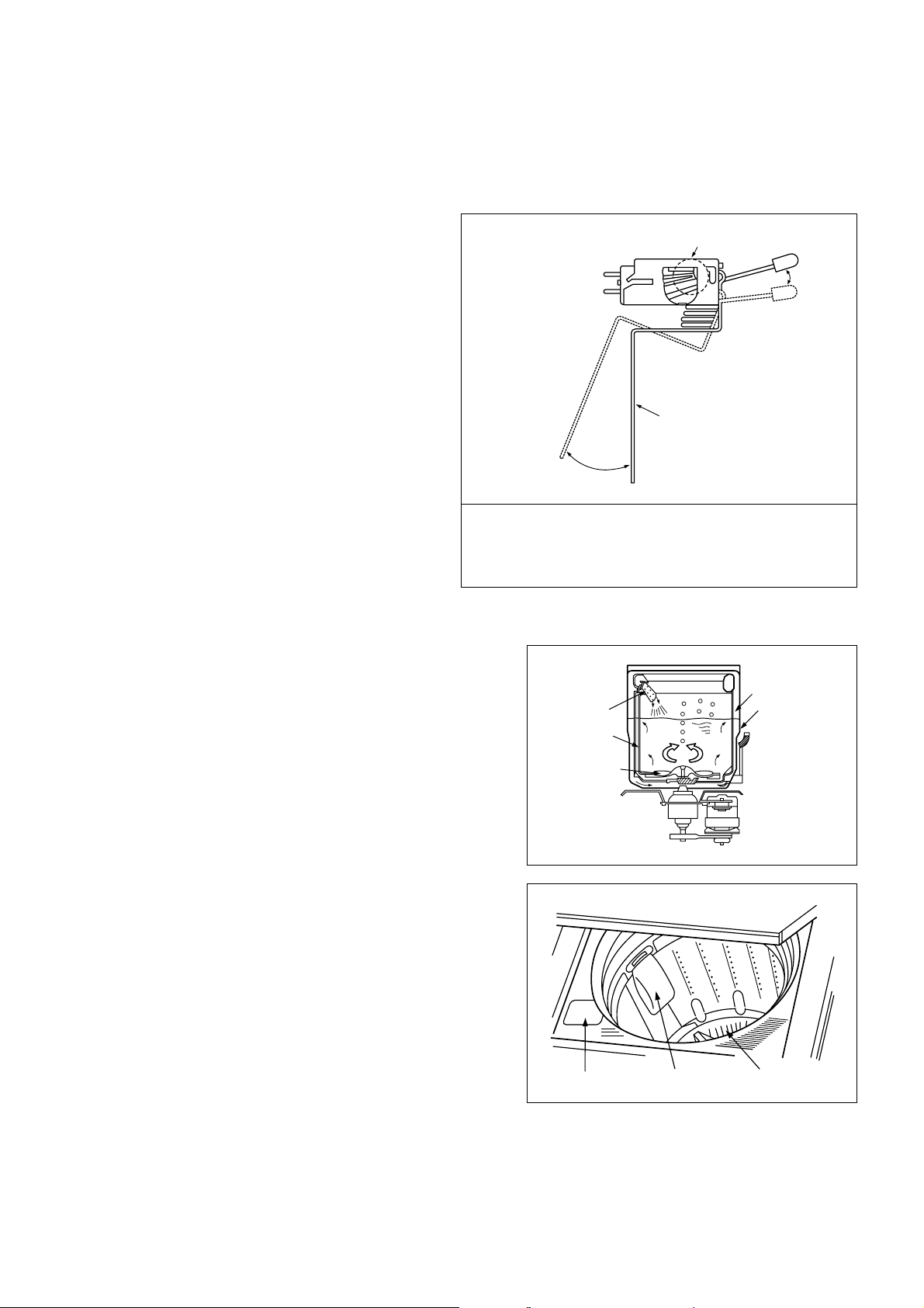
DRAIN MOTOR
STRUCTURE
FUNCTIONAL PRINCIPLE
1. When the DRAIN MOTOR connected to the power source (AC 220V), the DRAIN MOTOR rotates with 900 r.p.m and
revolves the pulley by gear assembly for reducing.
2. When the pulley is rotated, the pulley winds the wire to open the drain valve.
3. Therefore, rotation of pulley is changed to the linear moving of wire.
4. The wire pulls the brake lever of Gear Mechanism Ass'y within 5 seconds.
5. After the wire pulled, gear assembly is separated from motor and condition of pulling is held by operation of the lever.
6. When the power is turned off, the drain valve is closed because the wire returns to original position.
WATER LEVEL SWITCH
Water pressure of air room which is at the side of outer-tub is transmitted to the air room in the water level switch through
air-tube. Diaphragm moves up and down by the transmitted pressure to move the core.
Movement of core transforms the inductance of coil by Henly's Law.
The generative frequency (Hertz) is obtained by this transformation of the coil inductance in the LC generative circuit.
‚
Pull
Loosen
Pulley
Lever
Inductive ring
Magnet
Coil of motor
Magnet of motor
Spring
Spring
Coil
Case
Core
Diaphragm
(rubber)
Coil
Core
Diaphragm
Case
Air-pressure
10
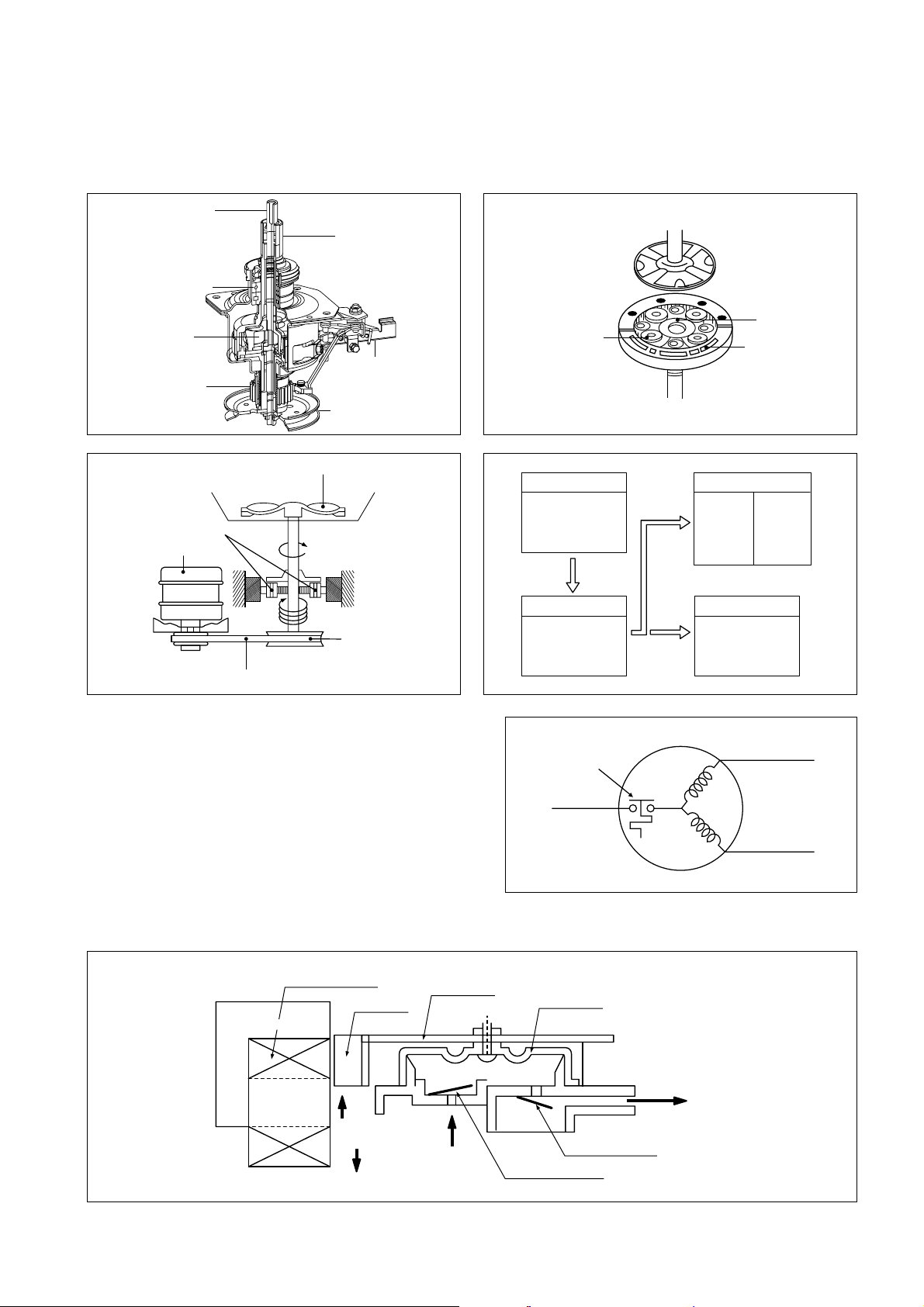
GEAR MECHANISM ASS'Y
The proper water currents is made by the rotation of pulsator at a low speed (about 145 r.p.m) to prevent the damage to
the small sized clothes.
SAFETY DEVICE FOR MOTOR
In case of occurring disorder of motor caused by extreme-high
voltage, over-heating, overload, safety devices (Thermal
Protector) of motor can be operated and cut off the power
sources automatically.
At this case, motor does not run.
However, motor can be operated normally again about 1 hour
later.
PRINCIPLE OF BUBBLE GENERA TOR
STRUCTURE
Pusator Shaft
Spinner Shaft
Roller Clutch
Bearing
Planetary
Gear
Clutch Boss
Brake Lever
Spinner Pulley
(Motor)
Sun gear
Planetary gear
Internal gear
Pulsator
Planetary
Motor
V-Belt
1 revolution
5 revolutions
Spinner
pulley
Motor
1700 r.p.m
(60Hz)
1400 r.p.m
(50Hz)
V.BELT
Spinner Pulley
650 r.p.m
(60Hz)
740 r.p.m
(50Hz)
Thermalprotector
White/Red
Planetary
gear
Directly
Pulsator
140 r.p.m
(60Hz)
150 r.p.m
(50Hz)
TUB
650 r.p.m
(60Hz)
740 r.p.m
(50Hz)
60 r.p.m
(60Hz)
70 r.p.m
(50Hz)
Dry/Silk
Violet
Blue
Bobbin & coil
Trans core
Magnet
Air
Air
Armature
Air in hole
Bellows
Air out hole
Protector A
Protector B
11
PRINCIPLE OF INTAKE & OUTLET OF THE AIR
INTAKE : ARMATURE moves to the upper side, and BELLOWS inhales the air. At same time, PROTECTOR B is open and A
is close.
OUTLET: ARMATURE moves to the down side, and BELLOWS exhaust the air. At same time, PROTECTOR B is close and
A is open.
FUNCTIONAL PRINCIPLE OF TRANS & MAGNET
• A.C electric power's phase changes to 60 cycle/sec.
• Trans core's magnetic pole is changed by changing of A.C electric power's phase.
• The core repeat push and pull (3600 times/min) the armature magnet.
FUNCTIONAL PRINCIPLE OF BUBBLE WASHING MACHINE
ACROSS SECTION
FUNCTIONAL PRINCIPLE
Bubble generator supplies the air from the bottom of outer tub to the inner space of pulsator, the air break up by pulsator's
agitating spin. Air-bubble was created by the centrifugal force, and rise up.
A.C A.C
N
S
NS
Magnet
Pan spring
Trans core
S
N
NS
Air bubble
Tub
Outer tub
Pulsator
Nozzle
12
3. STRUCTURE OF THE WASHING MACHINE
UP
• COLD WATER INLET
After using the machine,
close the water faucet
and turn off the power.
• DETERGENT CASE
• POWER SWITCH
• LINT FILTER
• PULSATOR
• HANDLE
• POWER CORD
• GROUNDING WIRE
In case of 3-pin power
cord grounding wire will
not be provided.
• HOT WATER INLET [Option]
• SOFTENER INLET
Pour softener into the softener
inlet and it will be added the
tub just before the final rinse.
• BLEACH INLET
• CONTROL PANEL
• TUB
(SUS: DWF-8060
DWF-8090)
• UNDER BASE COVER
• BOTTOM BOARD COVER
[Option]
• LEG COVER
[Option]
STRUCTURE OF WASHING MACHINE
ACCESSORIES
Hose Clamp Water Tap Adapter (COLD)
Water Tap Adapter (HOT)
[option]
In case of screw-shaped inlet hoses
water tap adapters will be provided.
Under Base Cover
Bottom Board Cover [Option]
Drain Hose
[PUMP] [NON-PUMP]
Inlet Hose (COLD)
Inlet Hose (HOT) [Option]
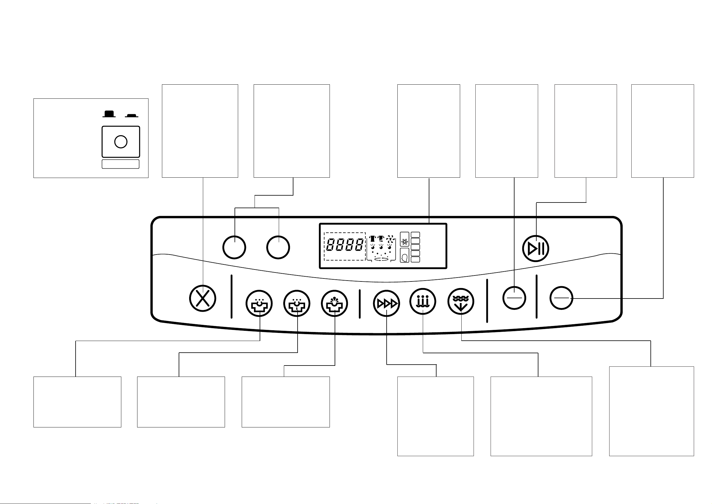
FUNCTION OF CONTROL P ANEL (DRY)
Control Panel
• It has micom sensor.
• As the button is pressed, course is
selected by your desired.
13
Use of Switch
• Power Switch
–Press to turn the
power On or Off
• After turning off
the power, wait
for over 3
seconds and then
turn it On again.
ON
OFF
AUTO OFF
WASH
RINSE
SPIN
COURSE
WASH TEMP.
WATER LEVEL
START/HOLD
CANCEL
RES HOUR
DAEWOO AUTOMATIC
WASHER
AERO FUZZY & AIR POWER
ONLY
SPIN
FUZ.
MEM.
DRY
SILK
SPEE
STRO
BLAN
WASH RINS SPIN
SOAK WASH RINS SPIN
HOUR MIN. TIME MIN.
RES. REM.
TIME
COURSE TEMP. LEVEL
HOT
WARM
COLD
H.
M.
L..
S.
E.S.
Dry cleaning
MEM
ORY
Time Display
•The lamps easily
indicate the option
selection of wash
program and
process by letters.
Button for Program
Cancel
• It can be used to cancel
the full-automatic course.
• When the button is
pressed time, display will
be light down.
If you want to wash, rinse
or spin, you can press
one of the other buttons.
Wash Time
Pre-engagement
• It can be used to preengage time for wash
Wash Time Selector
•It can be used to adjust
washing time.
Speed Time Selector
•It can be use to adjust
spin time.
Rinse Time Selector
•This button selects the
number of time you want
to rinse.
Course Selection
•It can be used to select
the full-automatic course.
•As the button is pressed,
it will be selected
following order;
DRY: Dry ¤ASilk ¤ASpeed ¤A
Strong ¤ABlanket ¤AFuzzy
Water Temperatur e
Selection [Option]
•It can be used to select the water
temperature according to the
clothes being washed.
•If you select 'Dry/Silk Washing',
selection for water temperature is
selected 'Cold' by automatically in
order to prevent the laundry from
damage.
Water Level Selector
•It can be used to adjust
amount of water according to
the size of the load to be
washed.
•If you select 'Dry/Silk
Washing', Selection for water
level is selected 'MID;
automatically in order to
prevent the laundry from
damage.
Memory Button
•It can be used by
remembering by
your desire.
Start/Hold Button
•Operation and
temporary stop are
repeated as it is
pressed.
•It will be repeated
(operation),
(temperary stop)
according to the one
time pressing or two
times pressing.
Exclusive Spin
Button
•It can be used to
spin exclusively.
FUNCTION OF CONTROL P ANEL (Non-Dry)
Control Panel
• It has micom sensor.
• As the button is pressed, course is
selected by your desired.
13-1
Use of Switch
• Power Switch
–Press to turn the
power On or Off
• After turning off
the power, wait
for over 3
seconds and then
turn it On again.
ON
OFF
AUTO OFF
WASH
RINSE
SPIN
COURSE
WASH TEMP.
WATER LEVEL
START/HOLD
CANCEL
RES HOUR
DAEWOO AUTOMATIC
WASHER
AERO FUZZY & AIR POWER
ONLY
SPIN
FUZ.
MEM.
SPEE
WOOL
STRO
NIGHT
BLAN
WASH RINS SPIN
SOAK WASH RINS SPIN
HOUR MIN. TIME MIN.
RES. REM.
TIME
COURSE TEMP. LEVEL
HOT
WARM
COLD
H.
M.
L..
S.
E.S.
Dry cleaning
MEM
ORY
Time Display
•The lamps easily
indicate the option
selection of wash
program and
process by letters.
Button for Program
Cancel
• It can be used to cancel
the full-automatic course.
• When the button is
pressed time, display will
be light down.
If you want to wash, rinse
or spin, you can press
one of the other buttons.
Wash Time
Pre-engagement
• It can be used to preengage time for wash
Wash Time Selector
•It can be used to adjust
washing time.
Speed Time Selector
•It can be use to adjust
spin time.
Rinse Time Selector
•This button selects the
number of time you want
to rinse.
Course Selection
•It can be used to select
the full-automatic course.
•As the button is pressed,
it will be selected
following order;
NON-DRY:
Speed ¤AWool¤A
Strong ¤ANigh t¤A Blanket
¤AFuzzy
Water Temperatur e
Selection [Option]
•It can be used to select the water
temperature according to the
clothes being washed.
•If you select 'Dry/Silk Washing',
selection for water temperature is
selected 'Cold' by automatically in
order to prevent the laundry from
damage.
Water Level Selector
•It can be used to adjust
amount of water according to
the size of the load to be
washed.
•If you select 'Dry/Silk
Washing', Selection for water
level is selected 'MID;
automatically in order to
prevent the laundry from
damage.
Memory Button
•It can be used by
remembering by
your desire.
Start/Hold Button
•Operation and
temporary stop are
repeated as it is
pressed.
•It will be repeated
(operation),
(temperary stop)
according to the one
time pressing or two
times pressing.
Exclusive Spin
Button
•It can be used to
spin exclusively.
 Loading...