

Daewoo DWF-270G Service Manual
SERVICE MANUAL
Automatic Washing Machine
Model:DWF-270G
Caution:
In this Manual, some parts can be changed for improving,their performance without notice in
Center (http://www.weili.com.cn).
the par ts list. So, if you Service Informationneed the latest parts information, please refer to the

WASHING MACHINE
Contents
1. SPECIFICATIONS................................................................................................................... 2
2. STRUCTURE OF THE WASHING MACHINE............................................................................. 3
3. DIRECTIONS FOR INSTALLATION AND USE............................................................................ 4
INSTALLATION OF THE UNDER BASE COVER .......................................................................................4
HOW TO INSTALL ON AN INCLINED PLACE.............................................................................................4
HOW TO CONNECT THE INLET HOSE ..........................................................................................................5
HOW TO CLEAN .........................................................................................................................................................6
4. FEATURE AND TECHNICAL EXPLANATION............................................................................... 7
FEATURE OF THE WASHING MACHINE......................................................................................................7
WATER CURRENT TO ADJUST THE UNBALANCED LOAD............................................................7
FUNCTION FOR SOAK WASH...........................................................................................................................7
AUTOMATIC WATER SUPPLY SYSTEM FOR WASH...........................................................................7
AUTOMATIC DRAINING TIME ADJUSTMENT ...........................................................................................8
CIRCULATING-WATER COURSE AND LINT FILTER .............................................................................8
RESIDUAL TIME DISPLAY ..........................................................................................................
........................ 8
5. DIRECTIONS FOR DISASSEMBLY AND ADJUSTMENT............................................................... 9
GEAR MECHANISM ASS’Y REPLACEMENT ...........................................................................................10
DRAIN MOTOR AND VALVE REPLACEMENT.........................................................................................11
6. TROUBLE SHOOTING GUIDE............................................................................................... 12
TEST PROGRAM (TEST WITHOUT WATER).......................................................................................12
7. .................................................................................18USAGE OF THE OPERATION BUTTONS
KEY POINTS IN DISSASSEMBLY................................................................ ............................... ..............9
METHOD OF DISASSEMBLING THE CONTROL PANEL.................................................................9
CONCERNING NO ACTION (THE INDICATOR IS OFF).......................................................................12
CONCERNING NO ROTATION IN WASHING ................................................................. ............................13
CONCERNING NO SPINNING ........................ ....................................................................... .. ...........................13
CONCERNING NO WATER FILLING .................................................................................... ...........................13
CONCERNING NO DRAINING ................................................................................................ ...........................14
CONCERNING KEEP FILLING WATER ............................................................................ ...........................14
CONCERNING TOO MUCH NOISE IN WASHING ........................................................ ...........................15
CONCERNING TOO MUCH NOISE IN SPINNING ......................................................... ..........................15
CONCERNING TIME-OUT IN BRAKE ............................................................................... ............ ..............16
TROUBLE-SHOOTING TABLE ............................................................................................... ............ ..............17
8. ................................................ ............................ 20CIRCUIT DIAGRAM ..................................................
9. ................................................ ................................. 22PARTS DIAGRAM ............................... ..
1. SPECIFICATIONS
2
SPECIFICATIONS
1 POWER SOURCE AVAILABLE IN ALL LOCAL AC VOLTAGE AND CYCLE
2 POWER CONSUMPTION
3 MACHINE WEIGHT
4 DIMENSION (WXHXD) 545 X 906 X 555
5 WASHING COURSE
FULL AUTOMATIC 8 COURSE
(NORMAL,HEAVY,SPEEDY,GENTLE,TUB SELF-CLEAN,
AIR DRY,WATER SAVING,FINE PURIFICTION )
6 WATER CONSUMPTION 145 L
7
WATER LEVEL SELECTOR
8 OPERATING WATER PRESSURE
50Hz
WASH : 125 - 140 RPM, SPIN : 630 - 660 RPM
9
60Hz
WASH : 125 - 140 RPM, SPIN : 630 -660 RPM
10
11 WATER LEVEL CONTROL
ELECTRONICAL SENSOR
12 GEAR MECHANISM ASS`S PLANET GEAR
13 LINT FILTER
YES
14 FUNCTION OF SOAK WASH YES
15 ALARM SIGNAL YES
16 RESIDUAL TIME DISPLAY YES
17 AUTO. WATER SUPPLY YES
18 AUTO RE-FEED WATER YES
19 AUTO POWER OFF YES
NO.
50Hz
60Hz
NON-PUMP
PUMP
27.8Kg
28.8Kg
340W
10
55 L
REVOLUTION
PER MINUTE
ITEM
9
50 L
8
45 L
7
40L
6
36 L
5
32 L
4
3
2
1
16 L
29 L
25 L
21L
0.03~0.78MPa
PULSATOR(mm)
6WINGS(Æ345mm)
DWF-270G
340W

2. STRUCTURE OF THE WASHING MACHINE
3
STRUCTURE
Accessories
The parts and features of your washer are illustrated on this page.
Become familiar with all parts and features before using your washer.
NOTE
©The drawing in this book may vary from your washer model. They are designed to show the different features
of all models covered by this book, Your model may not include all features.
the end connecting to
the water inlet hose jointer
the end connecting to
the washing machine
jointer connecting the
water inlet hose and
the water faucet
water inlet hose
(2pcs)
Water inlet
hose jointer
(2pcs)
(The two water inlet
hose components
are the same and
there's no different
on cool/warm water
during using)
Under cover(1pcs)
tapping screws(2pcs)
Inlet valve cap(including sealing plate)(1suit)
TOP L ID
HOT WATER TAP
After using the washer, close the water tap.
In case of the single valve model,
there is no hot water valve.
COLD WATER TAP
After using the washer,
close the water tap
LINT FILTER
CONTROL PANEL
ADJUSTABLE LEG
POWER SWITCH
PULSATOR
DETERGENT CASE
POWER CORD
PIPE
COLD VALVE
HOT VALVE
3. DIRECTIONS FOR INSTALLATION AND USE
4
DIRECTIONS
The openings must not
be obstructed by carpeting when the washing
machine is installed on a
carpeted floor.
Installation Of the COVER UNDER (Noise Insulation Plate)
How To Install On An Inclined Place
The place where it would be exposed to
direct sunlight.
The place nearby a heater or heat appli-
ance.
The place where it would be supposed
to be frozen in winter.
The kitchen with coal gas and a damp
place like a bathroom.
NOTES
10Cm
Install the washer on a horizontal
solid floor. If the washer is installed
on an unsuitable floor, it could make
considerable noise and vibration.
INSTALLING PLACE
Never install in these places
2
Push the noise insulation plate
into the end, which decrease
the noise made by this washer.
1
The packing box
opened, there is a
noise insulation plate
at the bottom of the
back
2
Check the Horizon
Status
Check the position of tub above
the center of the washer.
1
Horizon
Setting
After controlling the height
by turning the adjustable
leg, let the washer put
down to the ground.
Keep the machine body
more than 25cm apart from
the wall surface. It will
make easy cleaning the
drain filter which is equipped
at the back side of it. And if
it comes into contract vibration may occur.
* The drawing of the COVER UNDER is variant from your model
25cm
SCREW
UNDER COVER
BACK
FRONT
SOFT ITEM
Loosen
Fasten
High
Low
adjustable nut
adjustable foot

5
CONNECTION
HOW TO CONNECT THE INLET HOSE
Water faucet,suitable
Water faucet,not suitable
It is re qu ired th at t he front en d sh all be lo ng er than 1 0c m.
The ou tl et end su rf ace of the fa uc et shal l be f lat and s mo oth. If not p le ase fil e it t o avoid l ea kage.
2.Loosen the screw till the water faucet can be accessed. Put the jointer of the water inlet hose on the
faucet. See to Figure 2. (If the faucet is too large and the jointer can not be set on the water faucet,
please loosen the four screws and take out the bushing in the jointer. See to the figure.)
1.Press the lower end of the lock lever and push down the slider. Take off the water inlet hose jointer from
the water inlet hose component. See to Figure 1.
Rema rk s: Befo re i nstal la ti on, the t hr eadin g is 4 mm abov e th e upper sur fa ce of the n ut . After in st allatio n, t he thre ad ing
is 2mm a bo ve the up pe r surfa ce o f th e nut. Se e to F igure 6 .
4.Take off the nameplate. Twist the fastening nut as per the indication of the figure to
seal up the outlet end surface of the faucet. See to Figure 5.
3.Fasten the four screws evenly. See to Figure 4.
>10mm
Outlet end surface
Nut
About 4mm before twisting
About below 2mm after twisting
Figure 5
Figure 1
Figure 4
Figure 6
Slider
Water inlet pipe jointer
Water inlet pipe
Locking lever
Confirm the water faucet
Connection between the water inlet hose jointer and the water faucet
Screwdriver
Mark label
Figure 2
Screw
Liner
Figure 3
Connection between the water inl e t h o s e a n d t h e washin g m a chine
1.Do no t take off t he water absorption cus hion. Ple ase check i f
the cus hion is dro pped or damage d before ea ch usage.
If it hap pens please co ntact our a fter-sa le departmen t immedia tely.
2.Put t he nut of the wate r inlet hos e on the valv e jointer.
3.Fas ten the nut. Swi ng it gentl y to confirm if it 's suitab le.
Wat er ab sorpt ion cus hion
Nut o f the wat er inle t hose
Joi nter of t he wate r inlet v alve
Connection between the jointer of the water inle t h o s e a n d t h e
water inlet hose
Sli der
Loc king le ver
Joi nter of t he wate r inlet h ose
1.Pus h down the sl ider. Insert th e water inl et hose into the j ointer.
2.Han g the lock le ver to the joint er.Relea se the slider ti ll a click
sound i s heard.
Loc king le ver
Sli der
Dismantle the water i n l e t h o s e
1.Clo se the water fau cet.
2.Pre ss the lock ing lever. Push d own the sli der. Then p ull of the wa ter
inlet h ose. If the mach ine is used m ore than on ce every week, t he
joint er of the water in let hose ca n be kept on th e faucet to prev ent
damag ing the fixing s crew.
6
CONVENIENCE
HOW TO CLEAN
Remove the dirt
from the inlet filter
with a brush.
1
Pull the
power plug
out before
cleaning it.
2
Turn off the
water supply
to the washer
and sperate the
inlet hose.
3
CLEANING THE LINT FILTER
CLEANING THE WATER INLET FILTER
Clean the filter when water leaks from the water inlet.
CLEANING THE DETERGENT BOX
1
pull deter gent
box up slan tingly
and gen tly.
the
2
Clean t he
deter gent box wi th
water a fter
disma ntling it
3
put the d etergent box
down sl antingl y and
then pu sh in.
Dismantle
Install
CLEANING THE CABINET
If the ca binet is di r ty,
wipe it w ith wet cloth
Do not fl ush it dire ctly
with water.
Wipe it w ith neutral
deter gent.
Do not wi pe it with
thinn er, petrol ,
alcoh ol etc.
3
Return the filter as it was, and
insert the filter frame into the
slot.
1
Pull the Filter frame
upward. 2
Turn the lint filter
inside out, wash to
the lint off with water.
Filter Frame
Lint Filter
4. FEATURE AND TECHNICAL EXPLANATION
7
FEATURE
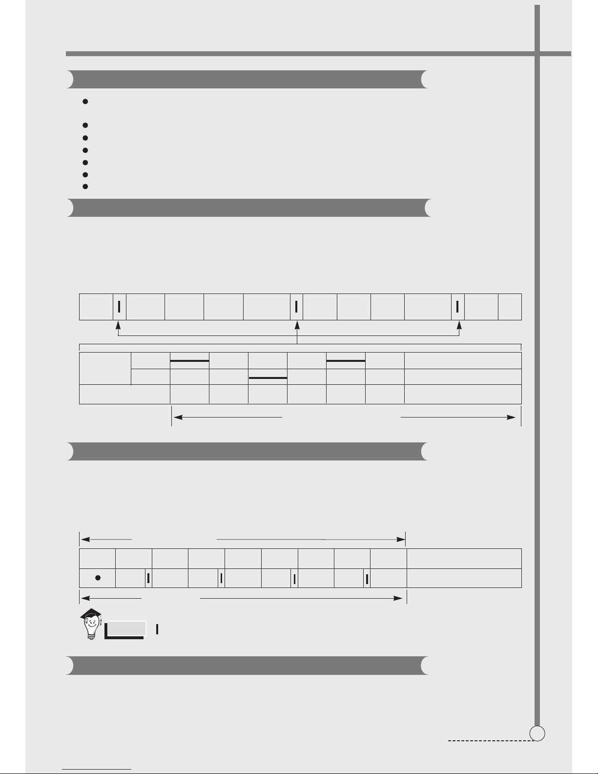
WASH DRAIN SPIN FILL RINSE 1
S PIN F ILL
DRAIN
RINSE 2 DRAIN
MOTOR C.W
SINGAL C.C.W
TIME(SEC.) 0.4 0.6 0.4 0.6 0.4 0.6
30 SEC. (About 30 Times)
FEATURE OF THE WASHING MACHINE
The first applying Radical Technology in the world....go beyond washing, sterilize your clothes and deodorize a
bad smell.
Quiet washing through the innovational low-noise design.
The adoption of the water currents to adjust the unbalanced load.
WATER CURRENT TO ADJUST THE UNBALANCED LOAD
It is a function to prevent eccentricity of the clothes after wash by rotating pulsator C.W and C.C.W for 30
seconds.(except for the course “soft” and “tub self-clean”.)
EFFECT
It reduces vibration and noise effectively while spinning.
WATER FLOW
FUNCTION FOR SOAK WASH
DISPLAY THE RESIDUAL TIME
When the SOAK WASH is selected, the total wash time increases because 20 minutes(“normal” , “self-clean”
and “water saving” course ) or 30 minutes(”heavy” and “fine purifition” course) for soak process are added to
PROGRESS
AUTOMATIC WATER SUPPLY SYSTEM FOR WASH
The water level would be lowered because the washings absorbs water at the beginning of washing. Therefore, after
some secs, the operation is interrupted to check the water level, and then the water is supplied again until the selected water level is reached.
" " mark indicates the operation of the water currents to adjust the unbalanced load.
NOTES
Transparency display window.
Self-cleaning tub.
Air-dry function.
......
...
FILL WASH STOP WASH STOP WASH STOP WASH STOP
SOAK PROCESS
MAIN PROCESS
30 Minutes
2' 3' 1'
4'
1' 9' 1' 9'
Fuzzy function.
the time of main process.
8
FEATURE
FUNCTIONAL PRINCIPLE
The micom can remember the time from the begining of drain to reset point when the pressure switch reaches
to”OFF”point
Draining
Good draining The washer begins spin process after drainage.
condition
Bad draining Draininig time is prolonged.
No draining Program is stopped and gives the alarm.
vement of the Program
Drain Time
Mo
Less than
Continue draining
4 minutes
More than
Program stops and gives the alarm with blinked on display lamp.
4 minutes
AUTOMATIC DRAINNING TIME ADJUSTMENT
This system adjusts the draining time automatically according to the draining condition.
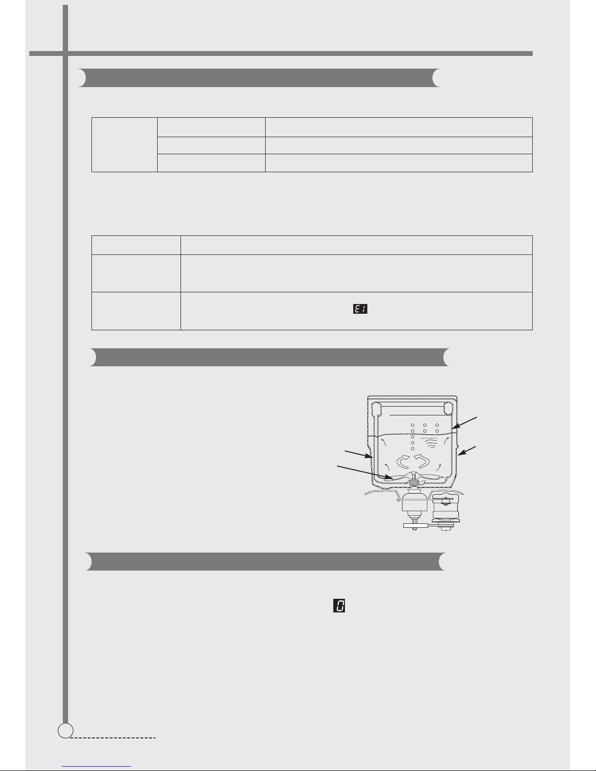
CIRCULATING-WATER COURSE AND LINT FILTER
Tub
Outer tub
Water
channel
Pulsator
CIRCULATING-WATER
The washing and rinsing effects have been
improved by adopting the water system in
wh i ch wa ter i n the tub i s cir c ulate d in a
designed pattern.
When the pulsator rotates during the washing
or rinsing process, the water below the pulsator fans creates a water currents as shown
in figure.
The water is then discharged from the upper
par t of the tub through the water channel.
About 40 L/min. water is circulated at the "8"
water level, standard wash load and standard
water currents.
When the START/PAUSE button is pressed, the residual time (min.) is displayed on the time indicator, and it will be
counted down according to process.
When operation is finished, the TIME INDICATOR will light up .
RESIDUAL TIME DISPLAY
5. DIRECTIONS FOR DISASSEMBLY AND ADJUSTMENT
9
DIRECTIONS
BEFORE ATTEMPTING TO SERVICE OR ADJUST ANY PART OF THE WASHING MACHINE, DISCONNECT
THE POWER CORD FROM THE ELECTRIC OUTLET.
Warning
1) GENERAL ATTENTION
2)POINTS OF ATTENTION IN USAGE OF ELECTRIC COMPONENTS
Take care of the screws in order to use them in installation.
In case that the power is on, the earthing circuit of the computer sequencer can have a high voltage to earth.
Take care not to get electric shock.
Store the computer sequencer at shading and dry places. Avoid direct sunlight.
KEY POINTS IN DISASSEMBLY
Be sure to pull off the power plug in disassembly or maintenance.
Use stipulated crimp terminals in connecting the wires between the conducting wires as far as possible, and
fix with suitable tools, and insulate with insulation tape completely.
In inserting the conducting wires, be sure to plug the pins to the root and make it hard to be pulled out.
If welding is needed, be careful not to touch the plastic or other insulation parts with the iron.
When connecting the wires, be sure not to make the wire touch the mobile parts like the belt, radiating pulley
and jib etc., and the sharp protruding parts and the parts with high temperature (motor).Connect and fix the
wires as per their original mode.
If there's metal object at the wire fixing point, be sure to insulate with insulation materials.
METHOD OF DISASSEMBLING THE CONTROL PANEL
1. Open the back cover. Loosen
the inner wiring.
2. Loosen the screws used to
install the control panel seat(rear
and side) .Lift the rear upwards.
Loosen the control panel seat from
the inlay of the cabinet. Then move
it forwards several times.
3.Turn the control panel seat
backwards to open it gently. Do not
open by force.
ATTENTION:
Do not lift the control panel seat by force, otherwise the safety switch control rod may get transformed, and the
jointer part of the connecting pipe of the water level sensor may be loosened, therefore influence the normal
operation of the microswitch and water level sensor.
After opening the control panel seat, hold it with one hand or lean it on supporter like the wall. Do not put it down.
POINTS OF ATTENTION IN ASSEMBLY
Fix the wiring in the control panel seat to its original position. Do not make it touch sharp corner and mobile position.
The space surrounding the computer sequencer is rather narrow. Please dispose it carefully and do not make the
transformer press the wires.
Confirm that the control panel seat is installed to proper position of the Cabinet.
 Loading...