

Daewoo DWF-270TAP, DWF-260KR, DWF-260KW, DWF-260KA Service Manual

Service Manual
Auto Washer
Model:
DWF-260KR/KA/KW
S/M No. : WF200KR001
DWF-270TAP
http : //svc.dwe.co.kr Feb. 2004

UTO W SHER UTO W SHER UTO W SHER UTO W SHER UTO W SHER UTO W SHER UTO W SHER UTO W SHER UTO
WASHER AUTO WASHER AUTO WASHER AUTO WASHER AUTO WASHER AUTO WASHER AUTO WASHER AUTO WASHER AUTO WASHER
AUTO WASHER AUTO WASHER AUTO WASHER AUTO WASHER AUTO WASHER AUTO WASHER AUTO WASHER AUTO WASHER AUTO
WASHER AUTO WASHER AUTO WASHER AUTO WASHER AUTO WASHER AUTO WASHER AUTO WASHER AUTO WASHER AUTO WASHER
AUTO WASHER AUTO WASHER AUTO WASHER AUTO WASHER AUTO WASHER AUTO WASHER AUTO WASHER AUTO WASHER AUTO
WASHER AUTO WASHER AUTO WASHER AUTO WASHER AUTO WASHER AUTO WASHER AUTO WASHER AUTO WASHER AUTO WASHER
AUTO WASHER AUTO WASHER AUTO WASHER AUTO WASHER AUTO WASHER AUTO WASHER AUTO WASHER AUTO WASHER AUTO
WASHER AUTO WASHER AUTO WASHER AUTO WASHER AUTO WASHER AUTO WASHER AUTO WASHER AUTO WASHER AUTO WASHER
WASHING MACHINE
CCoonntteennttss
1. SPECIFICA TIONS 2
2. STRUCTURE OF THE WASHING MACHINE 3
3. DIRECTIONS FOR INST ALLATION AND USE 4
INSTALLATION OF THE UNDER BASE COVER 4
HOW TO INSTALL ON AN INCLINED PLACE
4
HOW TO CONNECT THE INLET HOSE
5
HOW TO CLEAN THE FILTER
6
4. FEA TURE AND TECHNICAL EXPLANATION 7
FEATURE OF THE WASHING MACHINE 7
WATER CURRENT TO ADJUST THE UNBALANCED LOAD
7
AUTOMATIC WATER SUPPLY SYSTEM FOR BLANKET WASH
7
FUNCTION PRINCIPLE OF BUBBLE WASHING MACHINE
8
AUTOMATIC DRAINING TIME ADJUSTMENT
8
AUTOMATIC UNBALANCE ADJUSTMENT
9
CIRCULATING-WATER COURSE AND LINT FILTER
9
LINT FILTER
10
RESIDUAL TIME DISPLAY
10
DRAIN MOTOR
10
GEAR MECHANISM ASS’Y
11
5. DIRECTIONS FOR DISASSEMBLY AND ADJUSTMENT 12
GEAR MECHANISM ASS’Y REPLACEMENT 12
MOTOR SYNCRONOUS AND VALVE REPLACEMENT
14
6. THE REP AIR METHOD OF GEAR MECHANISM FOR CLUTCH
SPRING PROBLEM 15
THE STRUCTURE OF GEAR MECHANISM 15
HOW TO CHECK THE CLUTCH SPRING PROBLEM
16
THE PROCESS OF DISASSEMBLE
17
THE PROCESS OF ASSEMBLE
19
REPLACE THE CASE FILTER ASSY
21
7. TROUBLE SHOOTING GUIDE 22
CONCERNING WATER SUPPLY 22
CONCERNING WASHING
23
CONCERNING DRAINING
24
CONCERNING SPINING
25
CONCERNING OPERATING
26
8. PRESENT ATION OF THE P.C.B ASS’Y 27
APPENDIX
WIRING DIAGRAM 28
PARTS DIAGRAM
31
PARTS LIST
35
CIRCUIT DIAGRAM
38
1. SPECIFICATIONS
2
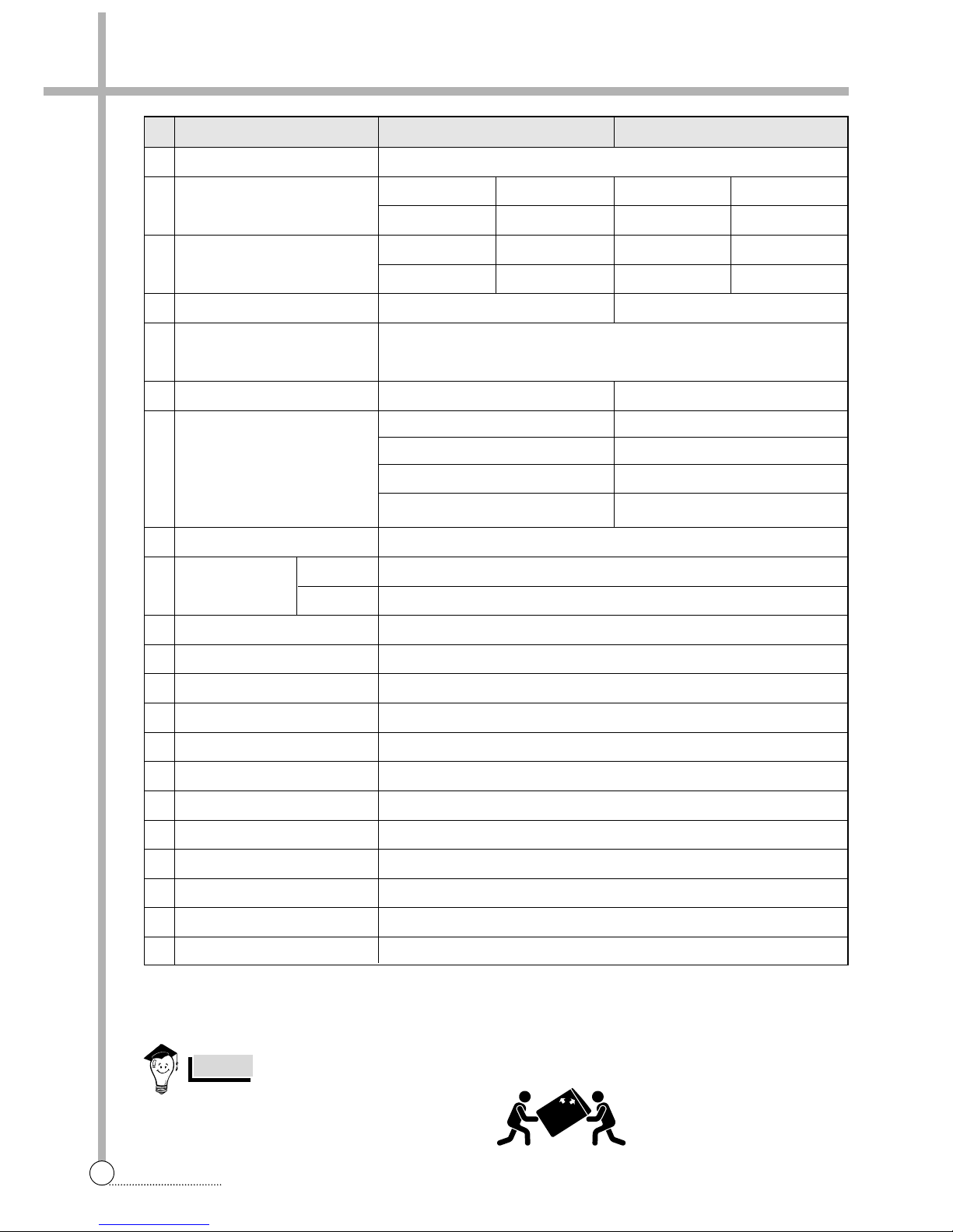
SPECIFICATIONS
NO. ITEM DWF-200KR/KA/KW DWF-270TAP
1 POWER SOURCE AVAILABLE IN ALL LOCAL AC VOLTAGE AND CYCLE
2 POWER CONSUMPTION
3 MACHINE WEIGHT
4 DIMENSION (WXHXD)
5 WASHING COURSE
6 WATER CONSUMPTION
7 WATER LEVEL SELECTOR
8 OPERATING W ATER PRESSURE 0.3kgf/cm
2
~8kgf/cm
2
(2.94 N/cm2~78.4N/cm2)
50Hz
60Hz
10 PULSAT OR 6 WINGS (Ø406mm)
11 WATER LEVEL CONTROL ELECTRONICAL SENSOR
12 GEAR MECHANISM ASS’Y HELICAL GEAR
13 LINT FILTER O
14 AUTO SOFTENER INLET O
15 FUNCTION FOR TIME DELAY O
16 ALARM SIGNAL O
17 RESIDUAL TIME DISPLAY O
18 AUTO. WATER SUPPLY O
19 FUNCTION FOR BUBBLE O
20 AUTO RE-FEED WATER O
21 AUTO POWER OFF O
50Hz
60Hz
480W
550W
50Hz
60Hz
550W
600W
NON-PUMP
47Kg
PUMP
48Kg
NON-PUMP
49Kg
PUMP
50Kg
FULL AUTOMA TIC 6 COURSE
(FUZZY, HEAVY, BLANKET , LIGHT, ECONOMY, WOOL)
630 X 1040 X 670 630 X 1060 X 670
180 L
HIGH 97 L
MEDIUM 77 L
LOW 66 L
E.LOW 42 L
210 L
HIGH 103 L
MEDIUM 87 L
LOW 70 L
E.LOW 43 L
WASH : 125 - 140 RPM, SPIN : 640 - 675 RPM
WASH : 130 - 150 RPM, SPIN : 710 -740 RPM
REVOLUTION
PER MINUTE
In case of moving Washing Machine, please
follow the following picture.
NOTES

DRYTEN [OPTION]
HOSE DRAIN [FOR PUMP]
COVER UNDER (OPTION)
HOSE DRAIN CLAMP
WA TER TAP ADAPTER
HOSE DRAIN[FOR NONPUMP]
INLET HOSE
CONNECTOR INLET [OPTION]
2. STRUCTURE OF THE WASHING MACHINE
3
STRUCTURE
• HOSE DRAIN
• POWER CORD
• LINT FILTER(2EA)
• HOT WATER TAP
• COLD WATER TAP
After using the washer,
close the water tap, In case
of the single valve model,
there is no hot water valve.
After using the washer,
close the water tap
In case of 3-wire power cord
ground wire will not be provided
(no existence to KR model)
• CASE DETERGENT
AND SOFTENER
• BLEACH INLET
• ADJUSTABLE LEG
• PULSATOR
• CONTROL PANEL
• NANO FILTER
• GROUND WIRE(OPTION)
A ccessories (Full Option)
The parts and features of your washer are illustrated on this page.
Become familiar with all parts and features before using your washer.
NOTE
• The drawings in this book may vary from your washer model.
They are designed to show the different features of all models covered by this book,
Your model may not include all features.
DRYTEN
UP
3. DIRECTIONS FOR INSTALLATION AND USE
4
DIRECTIONS
The openings must not
be obstructed by carpeting when the washing
machine is installed on a
carpeted floor.
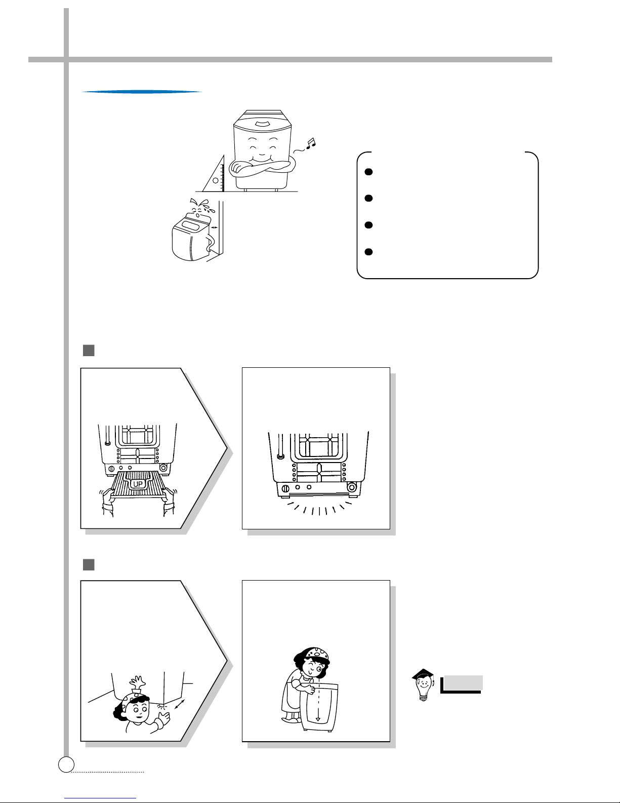
Installation Of The Noise Inulation Plate
How To Install On An Inclined Place
The place where it would be exposed to
direct sunlight.
The place nearby a heater or heat appli-
ance.
The place where it would be supposed
to be frozen in winter.
The kitchen with coal gas and a damp
place like a bathroom.
NOTES
10Cm
Install the washer on a horizontal
solid floor. If the washer is installed
on an unsuitable floor, it could make
considerable noise and vibration.
Installing Place
NNeevveerr iinnssttaallll iinn tthheessee ppllaacceess
2
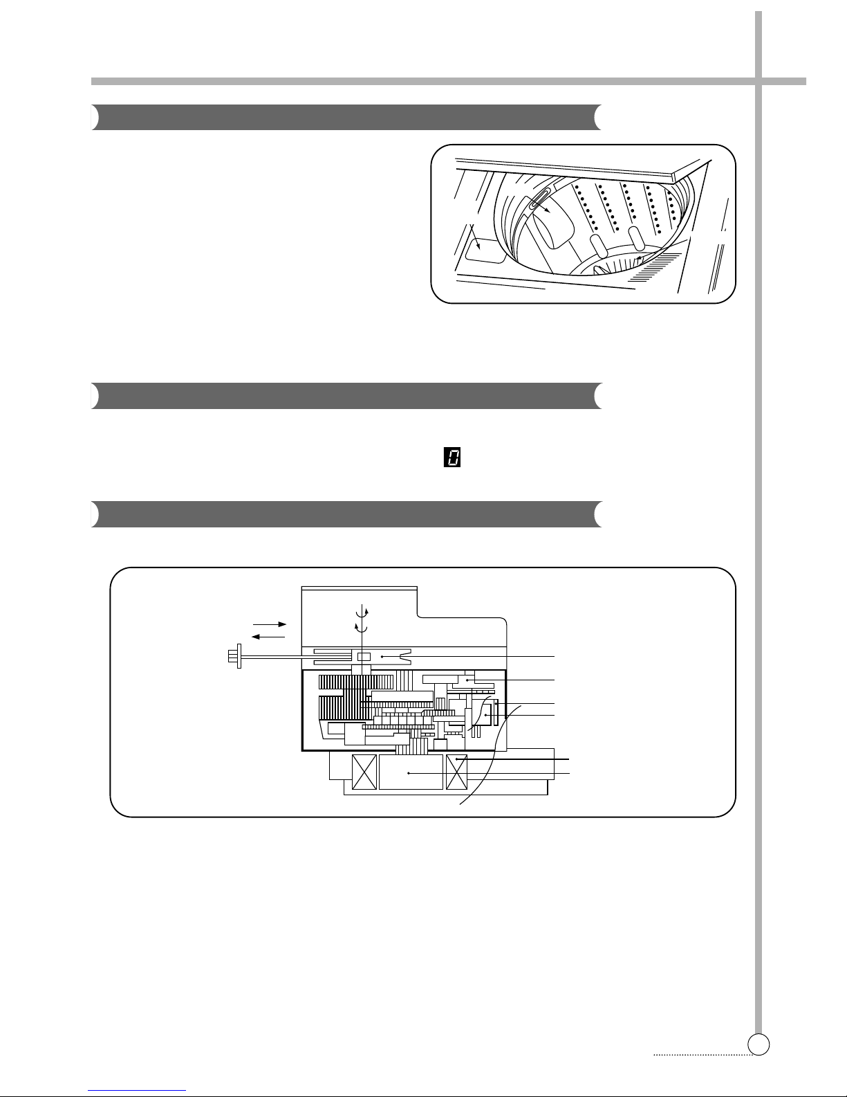
Push the noise insulation plate
into the end, which decrease
the noise made by this washer.
1
The packing box
opened, there is a
noise insulation plate
at the bottom of the back
2
Check the Horizon
Status
Check the position of tub above
the center of the washer.
1
Horizon
Setting
After controlling the height
by turning the adjustable
leg, let the washer put
down to the ground.
Keep the machine body
more than 25cm apart from
the wall surface. It will
make easy cleaning the
drain filter which is equipped
at the back side of it. And if
it comes into contract vibration may occur.
5
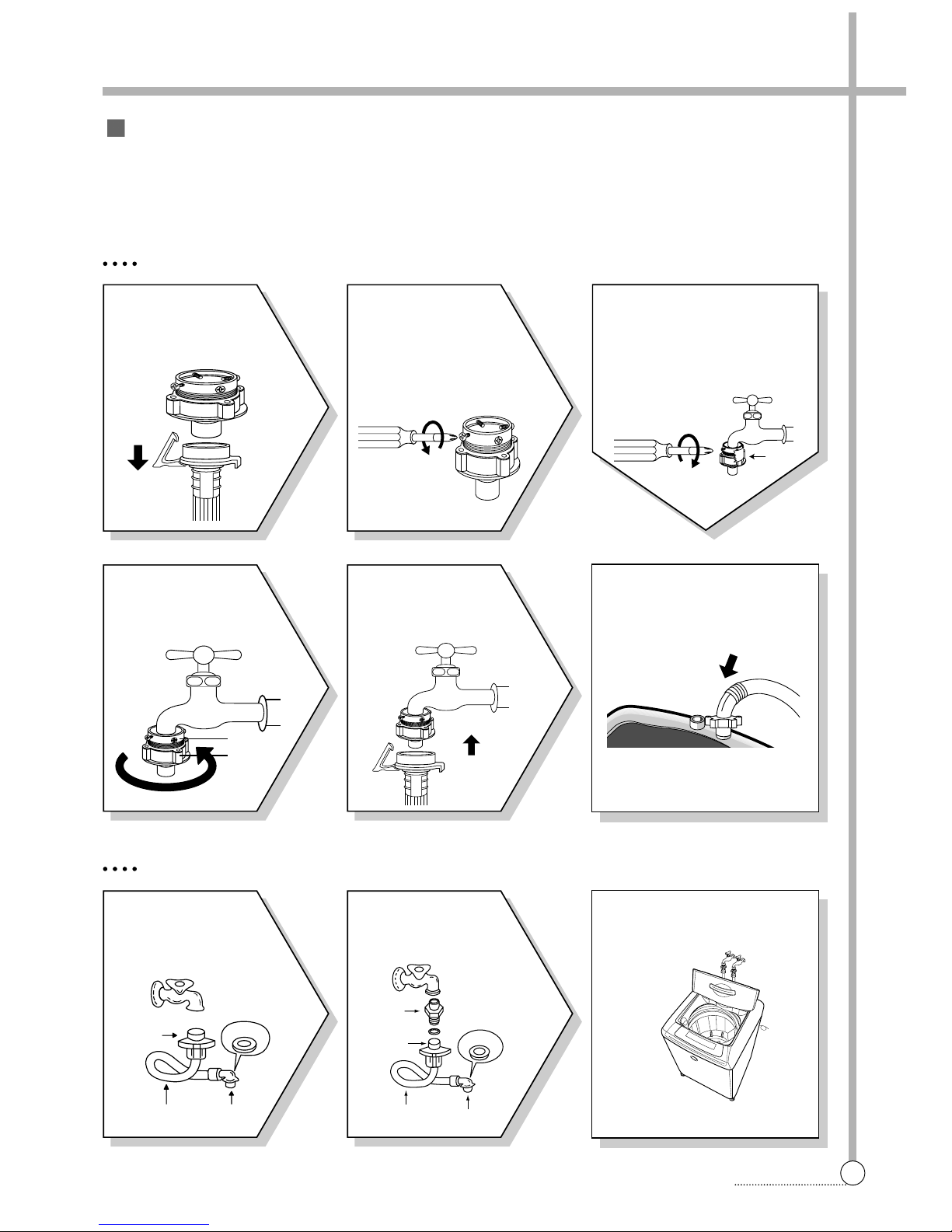
CONNECTION
FOR ORDINARY TAP
6
Connect the inlet hose adapter
of the hose to the water inlet of
the washer by turning it clockwise to be fixed tightly.
• Please check the rubber packing
inside the inlet hose adapter of
the hose.
1
Pull down the collar
of the inlet hose to
separate it from the
water tap adapter.
2
Loosen the four
screws at the water
tap adapter, but don’t
loosen the screws until
they are separated from
the water tap adapter.
4
Remove the tape,
and screw connector
B into connect A tightly.
5
Connect the inlet
hose to the water tap
adapter by puling down
the collar of the hose end.
3
Connect the water tap
adapter to the water tap tighten the four screws evenly
while pushing up the adapter
so that the rubber packing
can stick to the water tap
tightly.
How to Connect the Inlet Hose
Be careful not to mistake in supplying between the hot(maximum : 50˚C) and cold water.
In using only one water tap or in case of attached one water inlet valve, connect the inlet hose to the cold water inlet
valve.
Do not over tighten : this could cause damage to couplings.
FOR SCREW-SHAPED T A P
3
Insert the inlet hose adapter
into the water inlet of a washer
and turn it to be fixed.
• Check the packing in the inlet
1
Connect the inlet
hose to the water tap
by screwing the connector D tightly.
2
Connect the connector-inlet supplied if
necessary.
Inlet Hose
Connector D
Rubber
Packing
Connector C
Connector
Inlet
Rubber
Packing
Connector D
Connector C
Hose
TAPE
Connector B
Connector A
6
CONVENIENCE
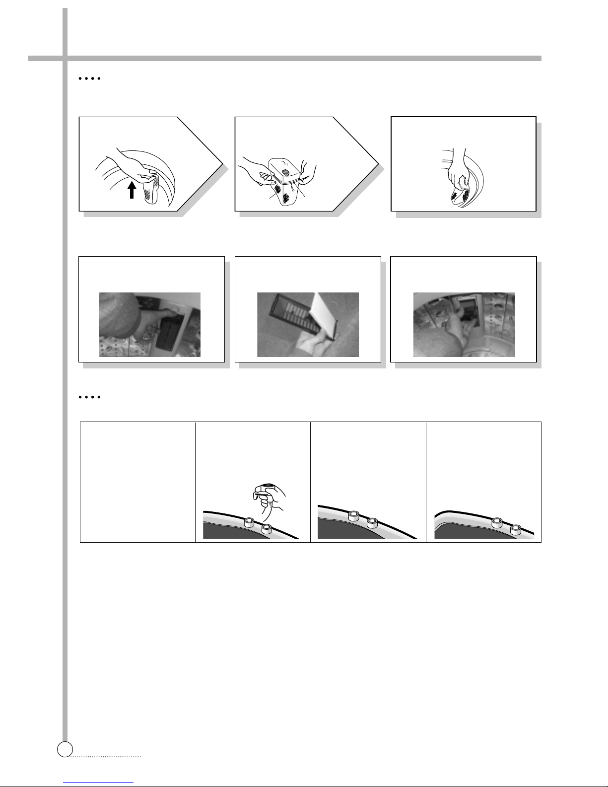
CLEANING THE LINT FILTER
• This washer has two type of lint Filter in order to increase lint filtering performance.
Type I : It is assembled in the top area of Tub.
Type II : It is assembled in the middle area of Tub.(no existence to KR model)
CLEANING THE WATER INLET FILTER
• Clean the filter when water leaks from, the water inlet.
3
Return the filter as it was, and
insert the filter frame into the
slot.
1
Pull the Filter frame
upward.
2
Turn the lint filter
inside out, wash to
the lint off with water.
Filter Frame
Lint Filter
1
Pull the button with pulling
upward.
2
Open the Cover and get rid of
lint being the Inside of Filter
then close the Cocer.
3
Assemble the Lint Filter as it
was, by pushing toward wall
with fixing slot
1Pull the power
plug out before
cleaning it.
2Turn off the water
supply to the
washer and
sperate the inlet
hose.
3Pull the inlet filter
out.
4Remove the dirt
from the inlet
filter with a brush.
7
CONVENIENCE
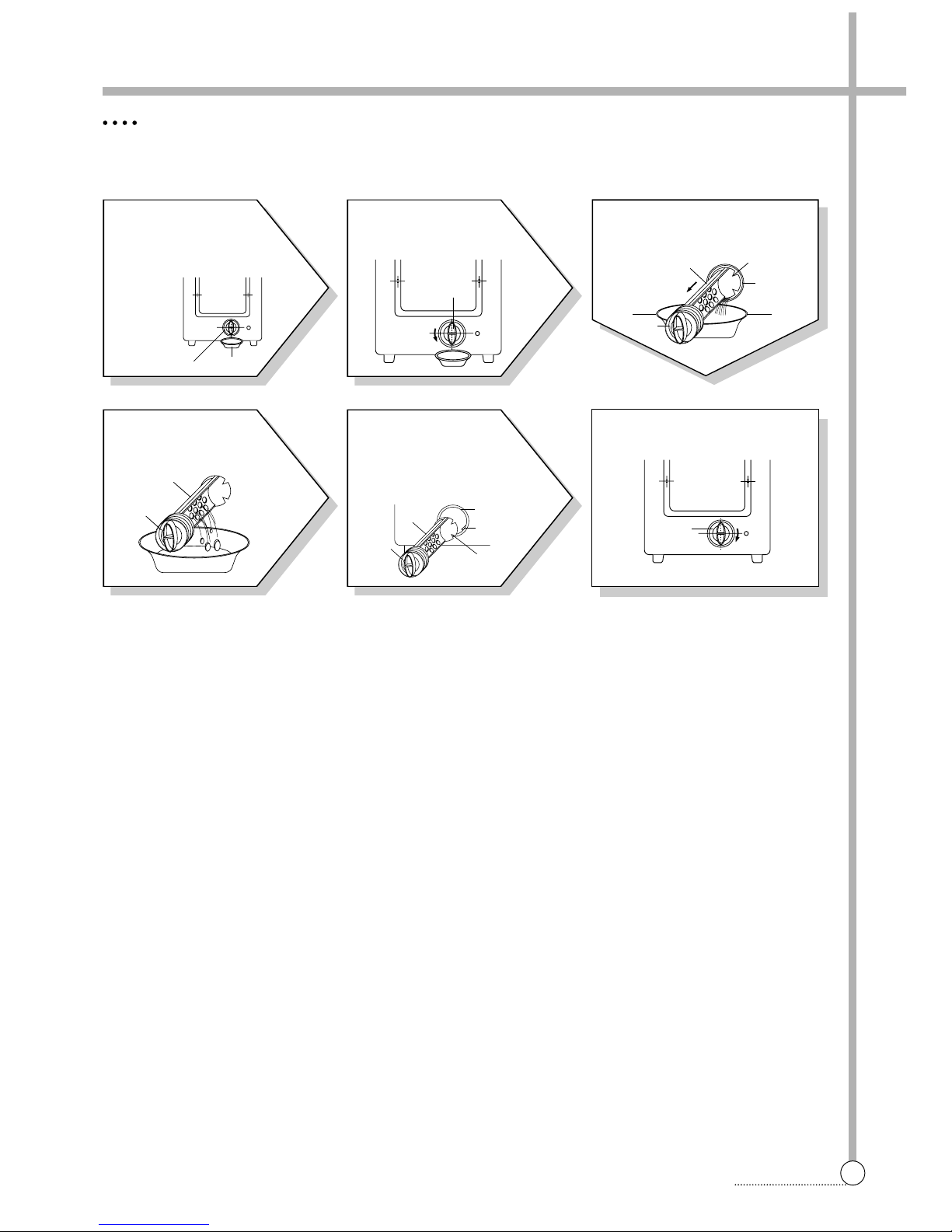
CLEANING THE DRAIN FILTER
• In case “U” shape drain hose, this filter’s equipped at the back side of washer.
• This drain filter is to screen the foreign stuffs such as threads, coins, pins, buttons etc ...
• If the drain filter is not cleaned at proper time (every 10 times of use), Drain problem could be caused.
1
Put down the
remained water in the
hose. And put a container
under the filter to collect
water.
2
Turn the cap counter
clockwise.
3
Pull out the filter assembly off
the case of the main body.
6
Turn the cap clockwise tightly.
4
Clean the drain filter
removing the foreign
stuffs.
5
Put in the filter along the
guiding prominence of the
case. Please note the left
position of the filter adjusting
the groove to the guide rib.
FILTER
CONTAINER
CAP
SLIT
CASE
FILTER
CAP
CAP
FILTER
CAP
FILTER
CASE
GUIDE
RIB
SLIT
CAP
8
FEATURE
4. FEATURE AND TECHNICAL EXPLANATION
WASH DRAIN SPIN FILL RINSE 1 DRAIN SPIN FILL RINSE 2 DRAIN •••
MOTOR C.W
SINGAL C.C.W
TIME(SEC.) 0.3 0.3 0.3 0.3 0.3 0.3 •••••••
35 SEC. (About 29 Times)
Feature of the Washing Machine
1 First applying the Radical Technology in the world ... go beyond washing, sterilize your colthes and deodorize a bad
smell.
2 The first air bubble washing system in the world.
3 Quiet washing through the innovational low-noise design.
4 Improving washing performance by more than 35%, while reducing power consumption by 40%.
5 The laundry detergent dissolves well in water because of the air bubble washing system.
6 The adoption of the water currents to adjust the unbalanced load.
7 One-touch operation system.
Water Current to Adjust the Unbalanced Load
It is a function to prevent eccentricity of the clothes after wash by rotating pulsator C.W and C.C.W for 35
seconds.(But, the SUIT course have no operation of the water currents to adjust the unbalnced load.)
EFFECT
It reduces vibration and noise effectively while spinning.
WATER FLOW
Automatic Water Supply System For Blanket Wash
The water level would be lowered because the blanket absorbs water at the beginning of washing. Therefore, after
2 minutes, the operation is interrupted to check the water level, and then the water is supplied again until the selected water level is reached.
9
FEATURE
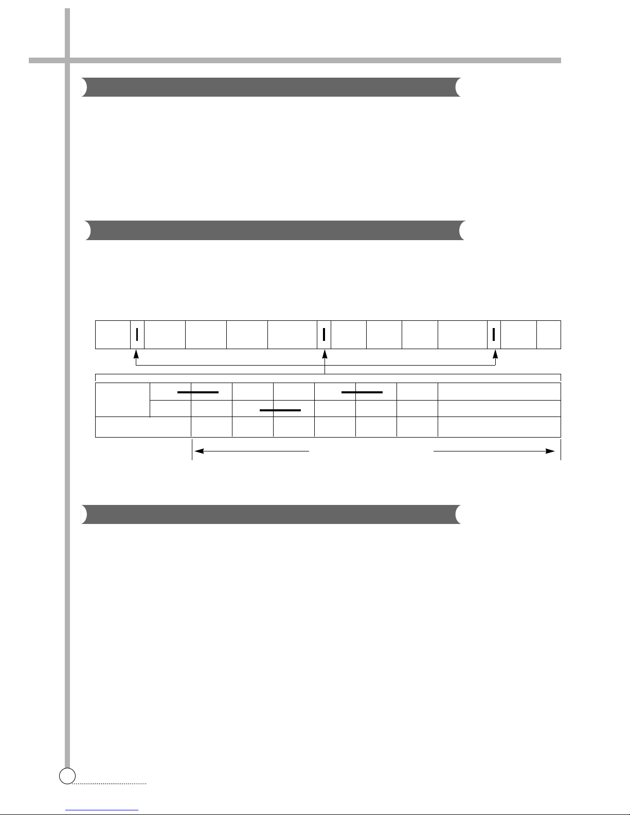
FUNCTIONAL PRINCIPLE
1 The micom can remember the time from the begining of drain to reset point when the pressure switch reaches to
“OFF” point
2 In case of continuous draining, residual drain time is determined by micom.
Draining time as a whole = D + 90
Residual drain time.
The time remembered by micom.
FUNCTIONAL PRINCIPLE
Bubble Motor supplies the air from the bottom of outer tub to the inner space of pulsator, the air is dispersed by the
rotation of pulsator. Air-bubble is created by the centrifugal force, and rises up.
Draining
Good draining The washer begins spin process after drainage.
condition
Bad draining Draininig time is prolonged.
No draining Program is stopped and gives the alarm.
Drain Time Movement of the Program
Less than
Continue draining
15 minutes
More than
Program stops and gives the alarm with blinked on display lamp.
15 minutes
Functional Principle of Bubble Washing Machine
ACROSS SECTION
Automatic Drainning time Adjustment
This system adjusts the draining time automatically according to the draining condition.
Air bubble
Tub
Outer tub
Pulsator
10
FEATURE
Contact of safety switch Lid closing
Lid opening
Contact lever A
Normal (ON)
Position of
unbalanced load (OFF)
Automatic Unbalance Adjustment
Circulating-Water Course and Lint Filter
The alarm finished when you close the lid after opening
it. Check the unbalance of the wash load and the installation condition.
NOTES
Filter
Tub
Outer tub
Water
channel
Pulsator
This system is to prevent abnormal vibration during intermittent spin and spin process.
FUNCTIONAL PRINCIPLE
1 When the lid is closed, the safety switch con-
tact is “ON” position.
2 In case that wash loads get uneven during
spin, the outer tub hits the safety switch
due to the serious vibration, and the spin
process is interrupted.
3 In case that P.C.B. ASS’Y gets “OFF” signal
from the safety switch, spin process are
stopped and rinse process is started automatically by P.C.B. ASS’Y.
4 If the safety switch is operated due to the
unbalance of the tub, the program is
stopped and the alarm is given.
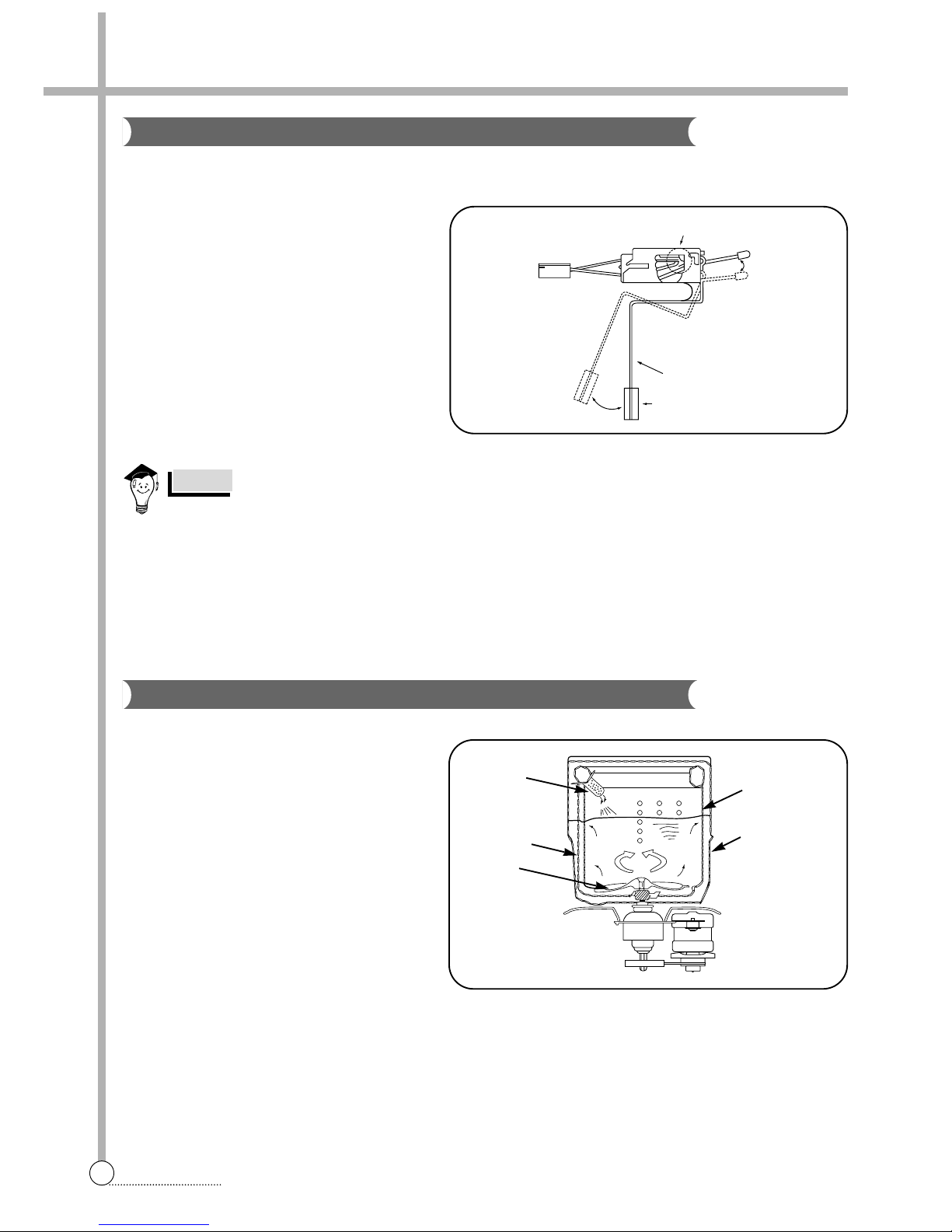
CIRCULATING-WATER
The washing and rinsing effects have been
improved by adopting the water system in
which water in the tub is circulated in a
designed pattern.
When the pulsator rotates during the washing
or rinsing process, the water below the pulsator fans creates a water currents as shown
in figure.
The water is then discharged from the upper
part of the tub through the water channel.
About 40 L/min. water is circulated at the ‘high’
water level, standard wash load and standard
water currents.
11
FEATURE
Much lint may be obtained according to the kind of
clothes to be washed and some of the lint may also
sticks to the clothes.
To minimize this possibility a lint filter is provided on
the upper part of the tub to filter the wash water as it
is discharged from the water channel. It is good to
use the lint filter during washing.
HOW TO REPLACE LINT FILTER
1 Pull the filter frame upward.
2 Turn the lint filter inside out, and wash the lint off with water .
3 Return the filter as it was, and fix the filter frame to the slot.
When the START/HOLD button is pressed, the residual time (min.) is displayed on the time indicator, and it will be
counted down according to process.
When operation is finished, the TIME INDICATOR will light up .
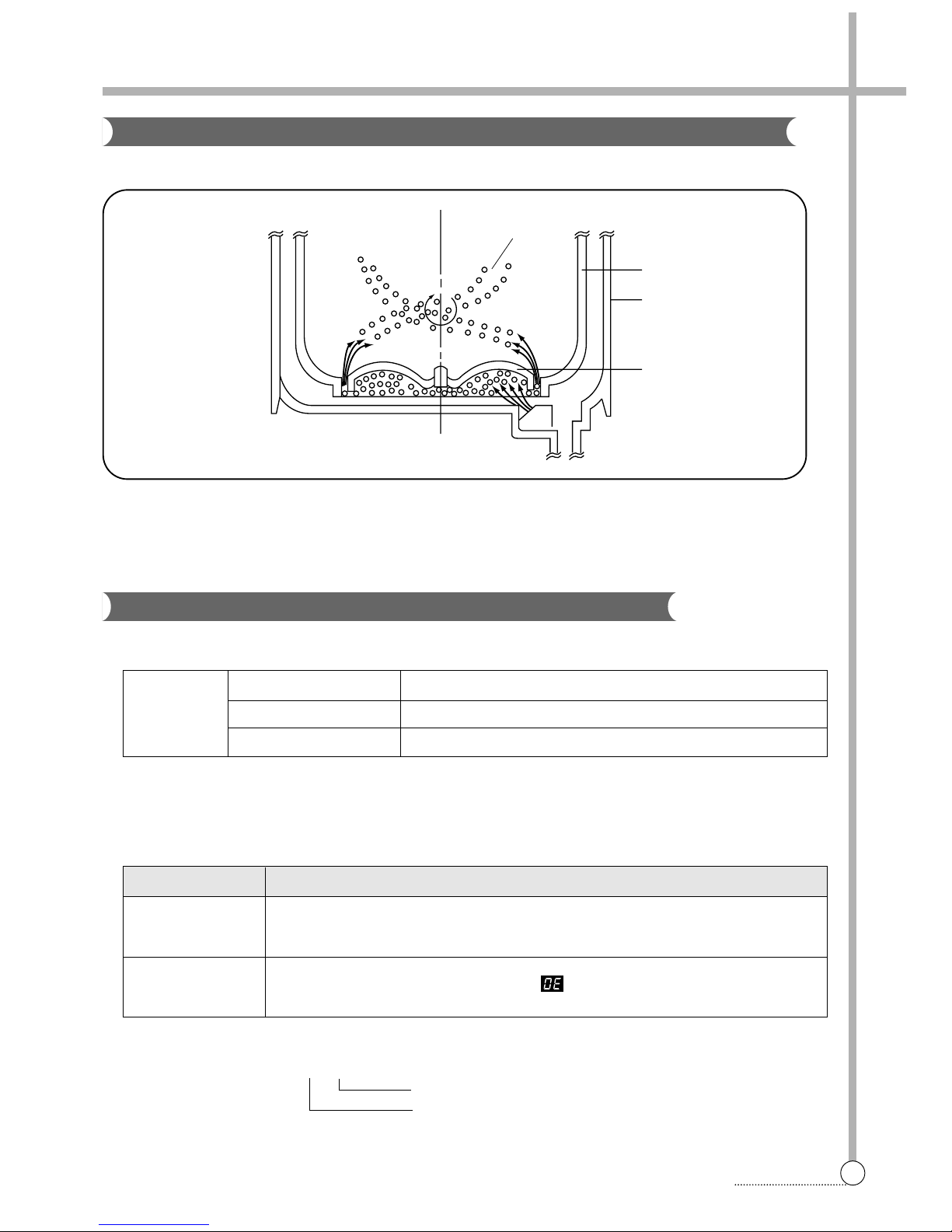
STRUCTURE
FUNCTIONAL PRINCIPLE
1 When the DRAIN MOTOR connected to the power source, the DRAIN MOTOR rotates with 900 r .p.m and revolves
the pulley by gear assembly for reducing.
2 When the pulley is rotated, the pulley winds the wire to open the drain valve.
3 Therefore, rotation of pulley changed to the linear moving of wire.
4 The wire pulls the brake lever of Gear Mechanism Ass’y within 5 seconds.
5 After the wire pulled, gear assembly is separated from motor and condition of pulling is held by operation of the
lever.
6 When the power is turned off, the drain valve is closed because the wire returns to original position.
Bleach Inlet
Filter
Pulsator
Pull
Loosen
Pulley
Lever
Inductive ring
Magnet
Coil of motor
Magnet of motor
Lint Filter
Residual Time Display
Drain Motor
Bleach
Inlet
Filter
Pulsator
12
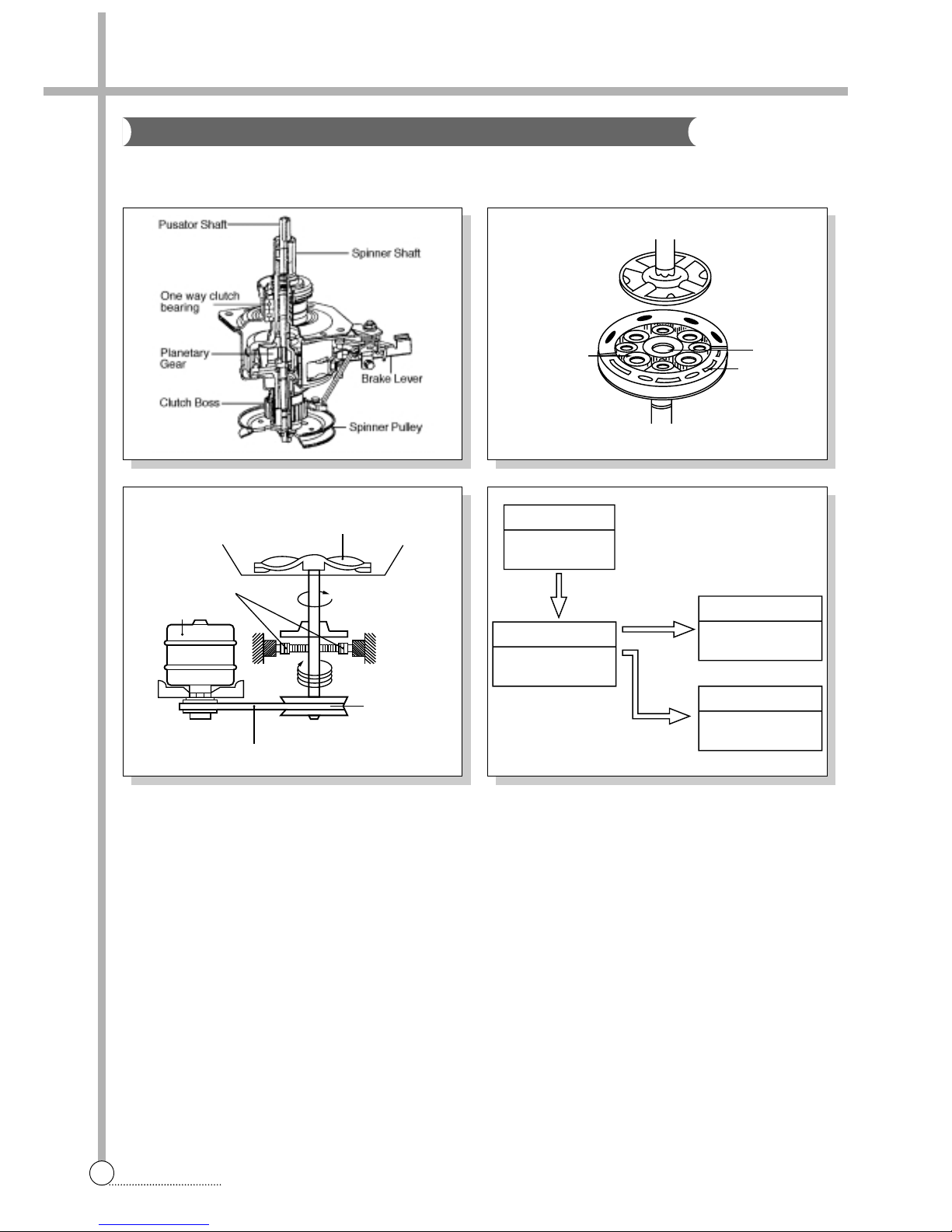
FEATURE
The proper water currents is made by the rotation of pulsator at a low speed to prevent the damage to the small
sized clothes.
Planetary gear
Sun gear
Internal gear
Pulsator
1 revolution
5 revolutions
Gear pulley
V-belt
Gear unit as
Motor
Motor
1800 r.p.m (60Hz)
1500 r.p.m (50Hz)
Gear Unit as
Directly
V.BELT
Tub
710-740r.p.m(60Hz)
640-675r.p.m(50Hz)
Pulsator
125-140r.p.m(60Hz)
130-150r.p.m(50Hz)
Spinner Pulley
710-740r.p.m(60Hz)
640-675r.p.m(50Hz)
Gear Mechanism Ass y
 Loading...