


Operator’s Manual
CanOBD2 Diagnostic Tool
The Easiest and Best Way to Troubleshoot 1996 and newer OBD2 Vehicles!
Model 87702
CAUTION: Before using this product, read this manual and follow all its Safety Rules and Operating Instructions.
For answers to your questions about this product, call:
1-800-544-4124 Craftsman Help Line
5 a.m. – 6 p.m., Mon. – Fri.
Sears, Roebuck and Co., Hoffman Estates, IL 60179 U.S.A.
Visit the Craftsman website: www.sears.com/craftsman

Table of Contents |
|
INTRODUCTION |
|
WHAT IS OBD? ........................................................................ |
1 |
YOU CAN DO IT! .............................................................................. |
2 |
SAFETY PRECAUTIONS |
|
SAFETY FIRST! ........................................................................ |
3 |
ABOUT THE DIAGNOSTIC TOOL |
|
VEHICLES COVERED ............................................................. |
5 |
BATTERY REPLACEMENT ..................................................... |
6 |
ADJUSTMENTS/SETTINGS AND DTC LIBRARY .................. |
6 |
DIAGNOSTIC TOOL CONTROLS |
|
CONTROLS AND INDICATORS ............................................. |
11 |
DISPLAY FUNCTIONS ............................................................ |
13 |
ONBOARD DIAGNOSTICS |
|
COMPUTER ENGINE CONTROLS ......................................... |
15 |
DIAGNOSTIC TROUBLE CODES (DTCs) .............................. |
20 |
OBD2 MONITORS .................................................................... |
23 |
PREPARATION FOR TESTING |
|
PRELIMINARY VEHICLE DIAGNOSTIC WORKSHEET ......... |
32 |
BEFORE YOU BEGIN .............................................................. |
35 |
VEHICLE SERVICE MANUALS ............................................... |
36 |
USING THE DIAGNOSTIC TOOL |
|
CODE RETRIEVAL PROCEDURE .......................................... |
37 |
ERASING DIAGNOSTIC TROUBLE CODES (DTCs) .............. |
43 |
I/M READINESS TESTING ...................................................... |
44 |
GLOSSARY |
|
INTRODUCTION....................................................................... |
50 |
GLOSSARY OF TERMS AND ABBREVIATIONS ................... |
50 |
WARRANTY AND SERVICING |
|
LIMITED ONE YEAR WARRANTY .......................................... |
53 |
SERVICE PROCEDURES ....................................................... |
53 |
i |
OBD2 |
Introduction
WHAT IS OBD?
WHAT IS OBD?
The CanOBD2 Diagnostic Tool is designed to work on all OBD2 compliant vehicles. All 1996 and newer vehicles (cars, light trucks and SUVs) sold in the United States are OBD2 compliant.
One of the most exciting improvements in the automobile industry was the addition of onboard diagnostics (OBD) on vehicles, or in more
basic terms, the computer that activates the vehicle’s “CHECK ENGINE” light. OBD1 was
designed to monitor manufacturer-specific systems on vehicles built from 1981 to 1995. Then came the development of OBD2, which is
on all 1996 and newer vehicles sold in the U.S. Like its predecessor, OBD2 was adopted as part of a government mandate to lower vehicle emissions. But what makes OBD2 unique is its universal application for all late model cars and trucks - domestic and import. This sophisticated program in the vehicle’s main computer system is designed to detect failures in a range of systems, and can be accessed through a universal OBD2 port, which is usually found under the dashboard. For all OBD systems, if a problem is found, the computer turns on the “CHECK ENGINE” light to warn the driver, and sets a Diagnostic Trouble Code (DTC) to identify where the problem occurred. A special diagnostic tool, such as the CanOBD2 Diagnostic Tool, is required to retrieve these codes, which consumers and professionals use as a starting point for repairs.
To learn more about vehicle Computer Control Systems and OBD2, see COMPUTER ENGINE CONTROLS on page 14.
OBD2 |
1 |
You Can Do It!
EASY TO USE - EASY TO VIEW - EASY TO DEFINE
Easy To Use . . . .
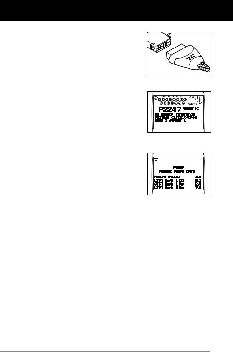
Connect the Diagnostic Tool to the vehicle’s test connector.
Turn the ignition key "On.”
Press the LINK button.
Easy To View . . . .
The Diagnostic Tool retrieves stored
codes, Freeze Frame data and I/M Readiness status.
Codes, I/M Readiness status and Freeze Frame data are displayed on the Diagnostic Tool’s LCD display screen. System status is indicated by LED indicators.
Easy To Define . . . .
Read code definitions from the Diagnostic Tool’s LCD display.
View Freeze Frame data.
2 |
OBD2 |
Safety Precautions
SAFETY FIRST!
SAFETY FIRST!
To avoid personal injury, instrument damage and/or damage to your vehicle; do not use the OBD2 Code Reader before reading this manual.
This manual describes common test procedures used  by experienced service technicians. Many test procedures
 require precautions to avoid accidents that can result in

 personal injury, and/or damage to your vehicle or test
 equipment. Always read your vehicle's service manual and
  follow its safety precautions before and during any test or
  service procedure. ALWAYS observe the following general
  safety precautions:
PR
ND
L
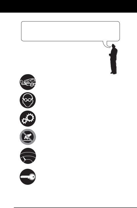
When an engine is running, it produces carbon monoxide, a toxic and poisonous gas. To prevent serious injury or death from carbon monoxide poisoning, operate the vehicle ONLY in a well-ventilated area.
To protect your eyes from propelled objects as well as hot or caustic liquids, always wear approved safety eye protection.
When an engine is running, many parts (such as the coolant fan, pulleys, fan belt etc.) turn at high speed. To avoid serious injury, always be aware of moving parts. Keep a safe distance from these parts as well as other potentially moving objects.
Engine parts become very hot when the engine is running. To prevent severe burns, avoid contact with hot engine parts.
Before starting an engine for testing or troubleshooting, make sure the parking brake is engaged. Put the transmission in park (for automatic transmission) or neutral (for manual transmission). Block the drive wheels with suitable blocks.
Connecting or disconnecting test equipment when the ignition is ON can damage test equipment and the vehicle's electronic components. Turn the ignition OFF before connecting the Diagnostic Tool to or disconnecting the Diagnostic Tool from the vehicle’s Data Link Connector (DLC).
OBD2 |
3 |

Safety Precautions
SAFETY FIRST!
To prevent damage to the on-board computer when taking vehicle electrical measurements, always use a digital multimeter with at least 10 megOhms of impedance.
Fuel and battery vapors are highly flammable. To prevent an explosion, keep all sparks, heated items and open flames away from the battery and fuel / fuel vapors. DO NOT SMOKE NEAR THE VEHICLE DURING TESTING.
Don't wear loose clothing or jewelry when working on an engine. Loose clothing can become caught in the fan, pulleys, belts, etc. Jewelry is highly conductive, and can cause a severe burn if it makes contact between a power source and ground.
4 |
OBD2 |
About the Diagnostic Tool
VEHICLES COVERED
VEHICLES COVERED
The CanOBD2 Diagnostic Tool is designed to work on all OBD2 compliant vehicles. All 1996 and newer vehicles (cars and light trucks) sold in the United States are OBD2 compliant.
Federal law requires that all 1996 and newer cars and light trucks sold in the United States must be OBD2 compliant; this includes all Domestic, Asian and European vehicles.
Some 1994 and 1995 vehicles are OBD2 compliant. To find out if a 1994 or 1995 vehicle is OBD2 compliant, check the following:
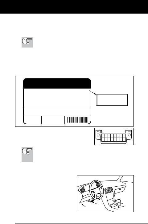
1.The Vehicle Emissions Control Information (VECI) Label. This label is located under the hood or by the radiator of most vehicles. If the vehicle is OBD2 compliant, the label will state “OBD II Certified.”
VEHICLE EMISSION CONTROL INFORMATION
|
ENGINE FAMILY |
EFN2.6YBT2BA |
OBD II |
VEHICLE |
DISPLACEMENT |
2.6L |
CERTIFIED |
THIS VEHICLE CONFORMS TO U.S. EPA AND STATE |
|||
MANUFACTURER |
OF CALIFORNIA REGULATIONS APPLICABLE TO |
||
|
1999 MODEL YEAR NEW TLEV PASSENGER CARS. |
||
|
|
|
|
REFER TO SERVICE MANUAL FOR ADDITIONAL INFORMATION TUNE-UP CONDITIONS: NORMAL OPERATING ENGINE TEMPERATURE, ACCESSORIES OFF, COOLING FAN OFF, TRANSMISSION IN NEUTRAL
EXHAUST EMISSIONS STANDARDS |
STANDARD CATEGORY |
||
|
|
|
|
CERTIFICATION |
TLEV |
||
IN-USE |
TLEV INTERMEDIATE |
||
SPARK PLUG
TYPE NGK BPRE-11 CATALYST
GAP: 1.1MM
OBD II
CERTIFIED
2.Government Regulations require that all OBD2 compliant vehicles must have a “common” sixteen-pin Data Link Connector (DLC).
1 |
2 |
3 |
4 |
5 |
6 |
7 |
8 |
9 10111213141516 |
|||||||
Some 1994 and 1995 vehicles have 16-pin connectors but are not OBD2 compliant. Only those vehicles with a Vehicle Emissions Control Label stating “OBD II Certified” are OBD2 compliant.
Data Link Connector (DLC) Location
The 16-pin DLC is usually |
|
|
|||||||
located |
under |
the |
instrument |
|
|
||||
panel (dash), within 12 inches |
|
|
|||||||
(300 mm) of center of the panel, |
|
|
|||||||
on the driver’s side of most |
|
|
|||||||
vehicles. |
It |
should |
be |
easily |
|
|
|||
accessible |
and |
visible |
from |
a |
|
|
|||
kneeling |
position outside the |
NEAR |
BEHIND |
||||||
CENTER |
ASHTRAY |
||||||||
vehicle with the door open. |
|
||||||||
|
LEFT CORNER OF DASH |
|
|||||||
|
|
|
|
|
|
|
OF DASH |
|
|
OBD2 |
5 |
About the Diagnostic Tool
BATTERY REPLACEMENT / ADJUSTMENTS/SETTINGS AND DTC LIBRARY
On some Asian and European vehicles the DLC is located behind the “ashtray” (the ashtray must be removed to access it) or on the far left corner of the dash. If the DLC cannot be located, consult the vehicle’s service manual for the location.
BATTERY REPLACEMENT
Replace batteries when the battery symbol  is visible on display and/or the 3 LEDS are all lit and no other data is visible on screen.
1.Locate the battery cover on the back of the Diagnostic Tool.
2.Slide the battery cover off (use your fingers).
3.Replace batteries with two AA-size batteries (for longer life, use Alkaline-type batteries).
4.Reinstall the battery cover on the back of the Diagnostic Tool.
Language Selection After Battery Installation
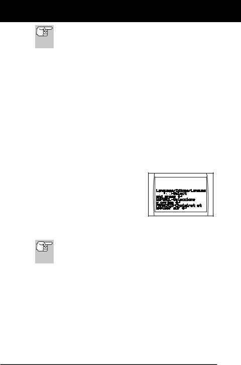
The first time the unit is turned on, you must select the desired display language (English, French or Spanish) as follows:
1.Press the POWER/LINK  button to turn the Diagnostic Tool “ON.”
The Select Language screen displays.
2.Use the UP  and DOWN
  buttons, as necessary, to highlight the desired display language.
3.When the desired display language is selected, press the ENTER/FF  button to confirm your selection.
After the initial language selection is performed, it, as well as other settings, can be changed as desired. Proceed to “ADJUSTMENTS/SETTINGS AND DTC LIBRARY” below for further instructions.
ADJUSTMENTS/SETTINGS AND DTC LIBRARY
The Diagnostic Tool lets you make several adjustments and settings to configure the Diagnostic Tool to your particular needs. It also contains an OBD2 DTC Library that allows you to search for DTC definitions. The following functions, adjustments and settings can be performed when the Diagnostic Tool is in “MENU Mode”:
Adjust Brightness: Adjusts the brightness of the LCD display screen.
DTC Library: Lets you search the library of OBD2 DTC definitions.
6 |
OBD2 |
About the Diagnostic Tool
ADJUSTMENTS / SETTINGS AND DTC LIBRARY
Select Language: Sets the display language for the Diagnostic Tool to English, French or Spanish.
Unit of Measurement: Sets the Unit of Measurement for the Diagnostic Tool’s display to USA or metric.
Adjustments and settings can be made only when the Diagnostic Tool is NOT connected to a vehicle.
To enter the MENU Mode:
1. With |
the Diagnostic Tool OFF, press |
|
and hold the UP |
button, then press |
|
and |
release the |
POWER/LINK |
button. |
|
|
The adjustments and setting MENU displays.
2.Release the UP  button.
DO NOT release the UP  button until the adjustments and settings MENU is visible on the display.
3.Make adjustments and settings as described in the following paragraphs.
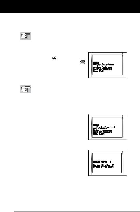
Adjusting Display Brightness
1.Use the UP  and DOWN
  buttons, as necessary, to highlight Adjust
Brightness in the MENU, then press the ENTER/FF  button.
The Adjust Brightness screen displays.
The Brightness field shows the current brightness setting, from 1 to 8.
2.Press the UP  button to decrease the brightness of the LCD display (make the display darker).
3.Press the DOWN  button to increase the brightness of the LCD display (make the display lighter).
4.When the desired brightness is obtained, press the ENTER/FF  button to save your changes and return to the MENU.
OBD2 |
7 |
About the Diagnostic Tool
ADJUSTMENTS / SETTINGS AND DTC LIBRARY
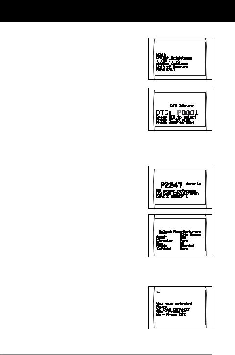
Searching for a DTC Definition Using the DTC Library
1. Use the UP  and DOWN
  buttons, as necessary, to highlight DTC Library in the MENU, then press the ENTER/FF
  button.
The Enter DTC screen displays. The screen shows the code “P0001”, with the “P” flashing.
2.Use the UP  and DOWN
  buttons,
  as necessary, to scroll to the desired
DTC type (P=Powertrain, U=Network,
B=Body, C=Chassis), then press the
DTC SCROLL  button.
The selected character displays “solid”, and the next character begins flashing.
3.Select the remaining characters in the DTC in the same way,
pressing the DTC SCROLL  button to confirm each character. When you have selected all the DTC characters, press the ENTER/FF
  button to view the DTC definition.
If you entered a “Generic” DTC  (DTCs that start with “P0”, “P2” and
some “P3”):
-The selected DTC and DTC definition (if available), show on the Diagnostic Tool’s LCD display.
If you entered a “Manufacturer-
Specific” DTC (DTCs that start with “P1” and some “P3”):
-The “Select Manufacturer” screen displays.
- Use the UP  and DOWN
  buttons, as necessary, to highlight
the appropriate manufacturer, then press the ENTER/FF  button to display the correct DTC for your vehicle. A confirmation message shows on the LCD display.
- If the correct manufacturer is shown, press the ENTER/FF  button to continue.
-If the correct manufacturer is not
shown, press the DTC SCROLL  button to return to the list of vehicle manufacturers.
8 |
OBD2 |
About the Diagnostic Tool
ADJUSTMENTS / SETTINGS AND DTC LIBRARY
If a definition for the DTC you entered is not available, an advisory message shows on the CanOBD2 Diagnostic Tool’s display.
4.If you wish to view definitions for additional DTCs, press the
ENTER/FF  button to return to the DTC Library screen, and repeat steps 2 and 3.
5.When all desired DTCs have been viewed, press the ERASE  button to exit the DTC Library.
Selecting the Display Language
1.Use the UP  and DOWN
  buttons, as necessary, to highlight Select
Language in the MENU, then press the
ENTER/FF  button.
The Select Language screen displays.
The currently selected display Language is highlighted.
2. Press the UP  or DOWN
  button, as necessary, to highlight the desired display language.
3.When the desired display language is highlighted, press the ENTER/FF  button to save your changes and return to the MENU (shown in the selected display language).
Setting the Unit of Measurement
1. Use the UP  and DOWN
  buttons, as necessary, to highlight Unit of Measurement in the MENU, then press the ENTER/FF
  button.
2.Press the UP  or DOWN
  button, as necessary, to highlight the desired
Unit of Measurement.
3.When the desired Unit of
Measurement value is selected, press the ENTER/FF  button to save your changes.
OBD2 |
9 |

About the Diagnostic Tool
ADJUSTMENTS / SETTINGS AND DTC LIBRARY
Exiting the MENU Mode
1.Use the UP  and DOWN
  buttons, as necessary, to highlight Menu Exit in the MENU, then press the ENTER/FF
  button.
The LCD display returns to the DTC screen (if data is currently stored in the Diagnostic Tool’s memory) or the “To Link” screen (if no data is stored).
10 |
OBD2 |
Diagnostic Tool Controls
CONTROLS AND INDICATORS
CONTROLS AND INDICATORS
|
11 |
|
10 |
7 |
8 |
6


 9 1
9 1 


 3 2
3 2 


 4
4
5
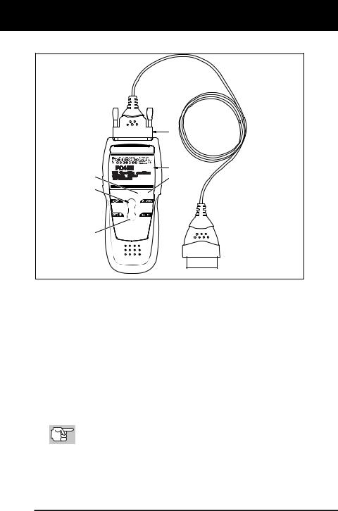
Figure 1. Controls and Indicators
See Figure 1 for the locations of items 1 through 11, below.
1. ERASE button - Erases Diagnostic Trouble Codes (DTCs), and “Freeze Frame” data from your vehicle’s computer, and resets Monitor status.
2. DTC SCROLL button - Displays the DTC View screen and/or scrolls the LCD display to view DTCs when more than one DTC is present.
3. POWER/LINK button - When the Diagnostic Tool IS NOT connected to a vehicle, turns the Diagnostic Tool “On” and “Off”. When the Diagnostic Tool is connected to a vehicle, links the Diagnostic Tool to the vehicle’s PCM to retrieve diagnostic data from the computer’s memory.
To turn the Diagnostic Tool "On", you must press and hold the POWER/LINK  button for approximately 3 seconds.
4. ENTER/FREEZE FRAME button - When in MENU mode, confirms the selected option or value. When retrieving and viewing DTCs, displays Freeze Frame data for the highest priority code.
OBD2 |
11 |

Diagnostic Tool Controls
CONTROLS AND INDICATORS
5. DOWN button - When in MENU mode, scrolls DOWN through the menu and submenu selection options. When retrieving and viewing DTCs, scrolls down through the current display screen to display any additional data.
6. UP button - When in MENU mode, scrolls UP through the menu and submenu selection options. When retrieving and viewing DTCs, scrolls ups through the current display screen to display any additional data.
7.GREEN LED - Indicates that all engine systems are running normally (all Monitors on the vehicle are active and performing their diagnostic testing, and no DTCs are present).
8.YELLOW LED - Indicates there is a possible problem. A “Pending” DTC is present and/or some of the vehicle’s emission monitors have not run their diagnostic testing.
9.RED LED - Indicates there is a problem in one or more of the vehicle’s systems. The red LED is also used to show that DTC(s) are present. DTCs are shown on the Diagnostic Tool’s LCD display. In this case, the Multifunction Indicator (“Check Engine”) lamp on the vehicle’s instrument panel will light steady on.
10.LCD Display - Displays settings Menu and submenus, test results, Diagnostic Tool functions and Monitor status information. See DISPLAY FUNCTIONS, on next page, for more details.
11.CABLE - Connects the Diagnostic Tool to the vehicle’s Data Link Connector (DLC).
12 |
OBD2 |

Diagnostic Tool Controls
DISPLAY FUNCTIONS
DISPLAY FUNCTIONS
2 |
1 |
11 |
12 |
13 |
3 |
|
|
|
|
4 |
|
|
|
|
5 |
|
|
|
|
6 |
|
|
|
14 |
7 |
|
|
|
10 |
|
|
|
|
|
8 |
|
|
|
9 |
Figure 2. Display Functions
See Figure 2 for the locations of items 1 through 16, below.
1.I/M MONITOR STATUS field - Identifies the I/M Monitor status area.
2.Monitor icons - Indicate which Monitors are supported by the vehicle under test, and whether or not the associated Monitor has run its diagnostic testing (Monitor status). When a Monitor icon is solid, it indicates that the associated Monitor has completed its diagnostic testing. When a Monitor icon is flashing, it indicates that the vehicle supports the associated Monitor, but the Monitor has not yet run its diagnostic testing.
3. Vehicle icon - Indicates whether or not the Diagnostic Tool is being properly powered through the vehicle’s Data Link Connector (DLC). A visible icon indicates that the Diagnostic Tool is being powered through the vehicle’s DLC connector.
4. Link icon - Indicates whether or not the Diagnostic Tool is communicating (linked) with the vehicle’s on-board computer. When visible, the Diagnostic Tool is communicating with the computer. If the Link icon is not visible, the Diagnostic Tool is not communicating with the computer.
5. Computer icon - When this icon is visible it indicates that the Diagnostic Tool is linked to a personal computer. An optional “PC Link Kit” is available that makes it possible to upload retrieved data to a personal computer.
6. Diagnostic Tool Internal Battery icon - When visible, indicates the Diagnostic Tool batteries are “low” and should be replaced. If the batteries are not replaced when the battery symbol
  is "on", all 3 LEDs will light up as a last resort indicator to warn you that the batteries need replacement. No data will be displayed on screen when all 3 LEDs are lit.
OBD2 |
13 |

Diagnostic Tool Controls
DISPLAY FUNCTIONS
7.DTC Display Area - Displays the Diagnostic Trouble Code (DTC) number. Each fault is assigned a code number that is specific to that fault.
8.Test Data Display Area - Displays DTC definitions, Freeze Frame data, and other pertinent test information messages.
9.FREEZE FRAME icon - Indicates that there is Freeze Frame data from “Priority Code” (Code #1) stored in the vehicle’s computer memory.
10.PERMANENT icon - Indicates the currently displayed DTC is a “Permanent” code.
11.PENDING icon - Indicates the currently displayed DTC is a “Pending” code.
12.MIL icon - Indicates the status of the Malfunction Indicator Lamp (MIL). The MIL icon is visible only when a DTC has commanded the MIL on the vehicle’s dashboard to light.
13.Code Number Sequence - The Diagnostic Tool assigns a sequence number to each DTC that is present in the computer’s memory, starting with “01.” This number indicates which code is currently displayed. Code number “01” is always the highest priority code, and the one for which “Freeze Frame” data has been stored.
If “01” is a “Pending” code, there may or may not be “Freeze Frame” data stored in memory.
14.Code Enumerator - Indicates the total number of codes retrieved from the vehicle’s computer.
14 |
OBD2 |

Onboard Diagnostics
COMPUTER ENGINE CONTROLS
COMPUTER ENGINE CONTROLS
The Introduction of Electronic Engine Controls
Electronic Computer Control Systems make it possible for vehicle manufacturers to comply with the tougher emissions and fuel efficiency standards mandated by State and Federal Governments.
As a result of increased air pollution (smog) in large cities,  such as Los Angeles, the California Air Resources Board
 (CARB) and the Environmental Protection Agency (EPA)

 set new regulations and air pollution standards to deal with
 the problem. To further complicate matters, the energy crisis of
  the early 1970s caused a sharp increase in fuel prices over a
short period. As a result, vehicle manufacturers were not only required to comply with the new emissions standards, they also
had to make their vehicles more fuel-efficient. Most vehicles
were required to meet a miles-per-gallon (MPG) standard set by the U.S. Federal Government.
Precise fuel delivery and spark timing are needed to reduce vehicle emissions. Mechanical engine controls in use at the time (such as ignition points, mechanical spark advance and the carburetor) responded too slowly to driving conditions to properly control fuel delivery and spark timing. This made it difficult for vehicle manufacturers to meet the new standards.
A new Engine Control System had to be designed and integrated with the engine controls to meet the stricter standards. The new system had to:
Respond instantly to supply the proper mixture of air and fuel for any driving condition (idle, cruising, low-speed driving, high-speed driving, etc.).
Calculate instantly the best time to “ignite” the air/fuel mixture for maximum engine efficiency.
Perform both these tasks without affecting vehicle performance or fuel economy.
Vehicle Computer Control Systems can perform millions of calculations each second. This makes them an ideal substitute for the slower mechanical engine controls. By switching from mechanical to electronic engine controls, vehicle manufacturers are able to control fuel delivery and spark timing more precisely. Some newer Computer Control Systems also provide control over other vehicle functions, such as transmission, brakes, charging, body, and suspension systems.
OBD2 |
15 |
 Loading...