


Owner’s Manual
Oil Lubricated
Single Stage
Horizontal Portable
AIR COMPRESSOR
Model No.
919.195411
•Safety Guidelines
•Assembly
•Operation
•Maintenance
•Service and Adjustments
•Troubleshooting
•Repair Parts
•Español
CAUTION: Read the Safety Guidelines
and All Instructions Carefully Before
Operating.
Sears, Roebuck and Co., Hoffman Estates, IL 60179 U.S.A.
Visit our Craftsman website: www.sears.com/craftsman
A09713 Rev. 0 1/3/05

TABLE OF CONTENTS
WARRANTY. . . . . . . . . . . . . . . . . . . . . . . . . . . . . . . . . . . . . . . . . . . . . . . . 2 SPECIFICATION CHART . . . . . . . . . . . . . . . . . . . . . . . . . . . . . . . . . . . . . 3 SAFETY GUIDELINES. . . . . . . . . . . . . . . . . . . . . . . . . . . . . . . . . . . . . . 3-8 GLOSSARY . . . . . . . . . . . . . . . . . . . . . . . . . . . . . . . . . . . . . . . . . . . . . . . . 9 ACCESSORIES . . . . . . . . . . . . . . . . . . . . . . . . . . . . . . . . . . . . . . . . . . . . 9 DUTY CYCLE . . . . . . . . . . . . . . . . . . . . . . . . . . . . . . . . . . . . . . . . . . . . . . 9 ASSEMBLY . . . . . . . . . . . . . . . . . . . . . . . . . . . . . . . . . . . . . . . . . . . . 10-12 INSTALLATION . . . . . . . . . . . . . . . . . . . . . . . . . . . . . . . . . . . . . . . . . 12-13 OPERATION . . . . . . . . . . . . . . . . . . . . . . . . . . . . . . . . . . . . . . . . . . . 14-16 MAINTENANCE. . . . . . . . . . . . . . . . . . . . . . . . . . . . . . . . . . . . . . . . . 17-19 SERVICE AND ADJUSTMENTS. . . . . . . . . . . . . . . . . . . . . . . . . . . . 20-22 STORAGE . . . . . . . . . . . . . . . . . . . . . . . . . . . . . . . . . . . . . . . . . . . . . . . . 23 TROUBLESHOOTING GUIDE . . . . . . . . . . . . . . . . . . . . . . . . . . . . . 24-27 REPAIR PARTS . . . . . . . . . . . . . . . . . . . . . . . . . . . . . . . . . . . . . . . . . 28-31 ESPAÑOL. . . . . . . . . . . . . . . . . . . . . . . . . . . . . . . . . . . . . . . . . . . . . . 32-57 NOTES . . . . . . . . . . . . . . . . . . . . . . . . . . . . . . . . . . . . . . . . . . . . . . . . . . 58 REPAIR PROTECTION AGREEMENTS. . . . . . . . . . . . . . . . . . . . . . . . . 59
HOW TO ORDER REPAIR PARTS . . . . . . . . . . . . . . . . . . . . . .Back Cover
AIR COMPRESSOR WARRANTY
FULL ONE YEAR WARRANTY AIR COMPRESSOR
If this CRAFTSMAN Air Compressor fails due to a defect in material or workmanship within one year from the date of purchase, Sears will at its option repair or replace it free of charge. Contact your nearest Sears
Service Center (1-800-4-MY-HOME®) to arrange for repair, or return the Air Compressor to the place of purchase for replacement.
If this Air Compressor is used for commercial or rental purposes, this warranty applies for only ninety days from the date of purchase.
This warranty gives you specific legal rights and you may have other rights which vary from state to state.
Sears, Roebuck and Co., Dept. 817WA, Hoffman Estates, IL 60179
A09713 |
2- ENG |

SPECIFICATION TABLE |
|
Model No. |
919.195411 |
Running HP |
2.0 |
Bore |
2.875" |
Stroke |
2.0" |
Voltage-Single Phase |
120/240 |
Minimum Branch Circuit Requirement |
15 amps |
Fuse Type |
Time Delay |
Air Tank Capacity |
25 gallons |
Approximate Cut-in Pressure |
120 |
Approximate Cut-out Pressure |
150 |
SCFM @ 40 psig |
8.6 |
SCFM @ 90 psig |
6.8 |
Refer to Glossary for abbreviations.
SAFETY GUIDELINES - DEFINITIONS
This manual contains information that is important for you to know and understand. This information relates to protecting YOUR SAFETY and
PREVENTING EQUIPMENT PROBLEMS. To help you recognize this information, we use the symbols below. Please read the manual and pay attention to these sections.
Indicates an |
Indicates a potentially |
imminently hazardous |
hazardous situation |
situation which, if not avoided, will |
which, if not avoided, may result in |
result in death or serious injury. |
minor or moderate injury. |
|
|
Indicates a potentially |
Used without the |
hazardous situation |
safety alert symbol |
which, if not avoided, could result in |
indicates a potentially hazardous |
death or serious injury. |
situation which, if not avoided, may |
|
result in property damage. |
|
|
IMPORTANT SAFETY INSTRUCTIONS
Some dust created by power sanding, sawing, grinding, drilling, and other construction activities contains chemicals known (to the State of
California) to cause cancer, birth defects or other reproductive harm. Some example of these chemicals are:
•lead from lead-based paints
•crystalline silica from bricks and cement and other masonry products
•arsenic and chromium from chemically-treated lumber
Your risk from these exposures varies, depending on how often you do this type of work. To reduce your exposure to these chemicals: work in a well ventilated area, and work with approved safety equipment, always wear MSHA/NIOSH approved, properly fitting face mask or respirator when using such tools.
When using air tools, basic safety precautions should always be followed to reduce the risk of personal injury.
3- ENG |
A09713 |
IMPORTANT SAFETY INSTRUCTIONS
Save these instructions
Improper operation or maintenance of this product could result in serious injury and property damage. Read and understand all warnings and operation instructions before using this equipment.
HAZARD
WARNING: Risk of explosion or fire
What Could Happen
It is normal for electrical contacts within the motor and pressure switch to spark.
If electrical sparks from compressor come into contact with flammable vapors, they may ignite, causing fire or explosion.
Restricting any of the compressor ventilation openings will cause serious overheating and could cause fire.
Unattended operation of this product could result in personal injury or property damage. To reduce the risk of fire, do not allow the compressor to operate unattended.
How To Prevent It
Always operate the compressor in a well ventilated area free of combustible materials, gasoline, or solvent vapors.
If spraying flammable materials, locate compressor at least 20 feet away from spray area. An additional length of hose may be required.
Store flammable materials in a secure location away from compressor.
Never place objects against or on top of compressor. Operate compressor in an open area at least 12 inches away from any wall or obstruction that would restrict the flow of fresh air to the ventilation openings.
Operate compressor in a clean, dry well ventilated area. Do not operate unit indoors or in any confined area.
Always remain in attendance with the product when it is operating.
Always disconnect electrical power by moving pressure switch lever to the off position and drain tank daily or after each use.
A09713 |
4- ENG |
HAZARD
WARNING: Risk of Bursting
Air Tank: The following conditions could lead to a weakening of the tank, and result in a violent tank explosion and could cause property damage or serious injury.
What Could Happen
Failure to properly drain condensed water from tank, causing rust and thinning of the steel tank.
Modifications or attempted repairs to the tank.
Unauthorized modifications to the unloader valve, safety valve, or any other components which control tank pressure.
Excessive vibration can weaken the air tank and cause rupture or explosion
ATTACHMENTS & ACCESSORIES:
Exceeding the pressure rating of air tools, spray guns, air operated accessories, tires, and other inflatables can cause them to explode or fly apart, and could result in serious injury.
How To Prevent It
Drain tank daily or after each use. If tank develops a leak, replace it immediately with a new tank or replace the entire compressor.
Never drill into, weld, or make any modifications to the tank or its attachments.
The tank is designed to withstand specific operating pressures. Never make adjustments or parts substitutions to alter the factory set operating pressures.
For essential control of air pressure, you must install a pressure regulator and pressure gauge to the air outlet (if not equipped) of your compressor. Follow the equipment manufacturers recommendation and never exceed the maximum allowable pressure rating of attachments. Never use compressor to inflate small low pressure objects such as children’s toys, footballs, basketballs, etc.
HAZARD
WARNING: Risk from Flying Objects
What Could Happen
The compressed air stream can cause soft tissue damage to exposed skin and can propel dirt, chips, loose particles, and small objects at high speed, resulting in property damage or personal injury.
How To Prevent It
Always wear ANSI Z87.1 approved safety glasses with side shields when using the compressor.
Never point any nozzle or sprayer toward any part of the body or at other people or animals.
Always turn the compressor off and bleed pressure from the air hose and tank before attempting maintenance, attaching tools or accessories.
5- ENG |
A09713 |

HAZARD
WARNING: Risk of Electrical Shock
|
What Could Happen |
How To Prevent It |
|
|
Your air compressor is powered by |
Never operate the compressor outdoors |
|
|
electricity. Like any other electrically |
when it is raining or in wet conditions. |
|
|
powered device, If it is not used |
Never operate compressor with |
|
|
properly it may cause electric shock. |
|
|
|
protective covers removed or damaged. |
|
|
|
|
|
|
|
|
|
|
|
Repairs attempted by unqualified |
Any electrical wiring or repairs required |
|
|
personnel can result in serious injury |
on this product should be performed by |
|
|
or death by electrocution. |
authorized service center personnel |
|
|
|
in accordance with national and local |
|
|
|
electrical codes. |
|
|
|
|
|
|
Electrical Grounding: Failure to provide |
Make certain that the electrical circuit |
|
|
adequate grounding to this product |
to which the compressor is connected |
|
|
could result in serious injury or death |
provides proper electrical grounding, |
|
|
from electrocution. |
correct voltage and adequate fuse |
|
|
See grounding instructions. |
protection. |
|
|
|
|
|
HAZARD
WARNING: Risk of Breathing
What Could Happen |
How To Prevent It |
The compressed air directly from your |
Air obtained directly from the compressor |
compressor is not safe for breathing. |
should never be used to supply air for |
The air stream may contain carbon |
human consumption. In order to use air |
monoxide, toxic vapors, or solid |
produced by this compressor for breathing, |
particles from the tank. Breathing these |
suitable filters and in-line safety |
contaminants can cause serious injury |
equipment must be properly installed. |
or death. |
In-line filters and safety equipment |
|
used in conjunction with the compressor |
|
must be capable of treating air to all |
|
applicable local and federal codes prior |
|
to human consumption. |
|
|
Sprayed materials such as paint, paint |
Work in an area with good cross |
solvents, paint remover, insecticides, |
ventilation. Read and follow the safety |
weed killers, may contain harmful |
instructions provided on the label or |
vapors and poisons. |
safety data sheets for the materials |
|
you are spraying. Use a NIOSH/ MSHA |
|
approved respirator designed for use with |
|
your specific application. |
|
|
A09713 |
6- ENG |

HAZARD
WARNING: Risk of Burns
What Could Happen
Touching exposed metal such as the compressor head or outlet tubes, can result in serious burns.
How To Prevent It
Never touch any exposed metal parts on compressor during or immediately after operation. Compressor will remain hot for several minutes after operation.
Do not reach around protective shrouds or attempt maintenance until unit has been allowed to cool.
HAZARD WARNING: Risk from Moving Parts
What Could Happen
Moving parts such as the pulley, flywheel, and belt can cause serious injury if they come into contact with you or your clothing.
Attempting to operate compressor with damaged or missing parts or attempting to repair compressor with protective shrouds removed can expose you to moving parts and can result in serious injury.
How To Prevent It
Never operate the compressor with guards or covers which are damaged or removed.
Any repairs required on this product should be performed by authorized service center personnel.
HAZARD
WARNING: Risk of Falling
What Could Happen
A portable compressor can fall from a table, workbench, or roof causing damage to the compressor and could result in serious injury or death to the operator.
How To Prevent It
Always operate compressor in a stable secure position to prevent accidental movement of the unit. Never operate compressor on a roof or other elevated position. Use additional air hose to reach high locations.
7- ENG |
A09713 |
HAZARD
WARNING: Risk of Serious Injury or Property Damage When Transporting Compressor
(Fire, Inhalation, Damage to Vehicle Surfaces)
What Could Happen
Oil can leak or spill and could result in fire or breathing hazard; serious injury or death can result. oil leaks will damage carpet, paint or other surfaces in vehicles or trailers.
How To Prevent It
Always place COMPRESSOR on a protective mat when transporting to protect against damage to vehicle from leaks. Remove COMPRESSOR from vehicle immediately upon arrival at your destination.
HAZARD
WARNING: Risk of Unsafe Operation
What Could Happen
Unsafe operation of your air compressor could lead to serious injury or death to you or others.
How To Prevent It
Review and understand all instructions and warnings in this manual.
Become familiar with the operation and controls of the air compressor.
Keep operating area clear of all persons, pets, and obstacles.
Keep children away from the air compressor at all times.
Do not operate the product when fatigued or under the influence of alcohol or drugs. Stay alert at all times.
Never defeat the safety features of this product.
Equip area of operation with a fire extinguisher.
Do not operate machine with missing, broken, or unauthorized parts.
SAVE THESE INSTRUCTIONS
A09713 |
8- ENG |

GLOSSARY
Become familiar with these terms before operating the unit.
CFM: Cubic feet per minute.
SCFM: Standard cubic feet per minute; a unit of measure of air delivery.
PSIG: Pounds per square inch gauge; a unit of measure of pressure.
Code Certification: Products that bear one or more of the following marks: UL, CUL, ETL, CETL, have been evaluated by OSHA certified independent safety laboratories and meet the applicable Underwriters Laboratories Standards for Safety.
Cut-In Pressure: While the motor is off, air tank pressure drops as you continue to use your accessory.
When the tank pressure drops to a certain low level the motor will restart automatically. The low pressure
at which the motor automatically restarts is called "cut-in" pressure.
Cut-Out Pressure: When an air compressor is turned on and begins to run, air pressure in the air tank begins to build. It builds to a certain high pressure before the motor automatically shuts off, protecting your air tank from pressure higher than its capacity. The high pressure at which the motor shuts off is called "cut-out" pressure.
Branch Circuit: Circuit carrying electricity from electrical panel to outlet.
ACCESSORIES
This unit is capable of powering the following Accessories. The accessories are available through the current Power and Hand Tool Catalog or full-line Sears stores.
Accessories |
• Air Hose:1/4", 3/8" or 1/2" inside |
• In Line Filter |
diameter in various lengths |
•Tire Air Chuck
• |
Quick Connector Sets (various |
Refer to the selection chart located |
|
|
sizes) |
||
|
on the unit to select the tools this unit |
||
• |
Air Pressure Regulators |
||
is capable of powering. |
•Oil Fog Lubricators
DUTY CYCLE
This air compressor pump is capable of running continuously. However, to prolong the life of your air compressor, it is recommended that a 50%-75% average duty
cycle be maintained; that is, the air compressor pump should not run more than 30-45 minutes in any given hour.
9- ENG |
A09713 |

|
ASSEMBLY |
|
|
||
Contents of Carton |
|
|
|
||
1 - |
Air Compressor |
|
|
|
|
2 - |
Wheels |
|
|
|
|
2 - |
Shoulder Bolts, 3/8-16 |
|
|
|
|
2 - |
Hex Nuts, 3/8-16 |
|
|
|
|
1 - |
Handle |
|
|
Open End |
|
1 - |
Handle Grip |
|
|
||
|
|
Of Saddle |
|||
2 - |
Cap Screws |
|
|
|
|
2 - |
1/4-20 Hex Nuts |
|
|
|
|
2 - |
Retainer Clips |
|
|
|
|
2 - |
Flat Washers |
Bent Tabs |
Saddle |
Open End |
|
Of Handle |
|||||
2 - |
Rubber Bumpers |
||||
|
|
||||
|
|
|
|||
2 - |
Screws, 1/4-20 x 3/4 |
3. Slowly push the open ends of |
|||
Tools Required for Assembly |
the handle onto both tabs at the |
||||
same time. Continue pushing the |
|||||
1 - |
9/16" socket or open end wrench |
||||
handle into the saddle until the |
|||||
1 - |
1/2" socket or open end wrench |
holes on the side of the saddle |
|||
|
|
and handle are in line. |
|||
Unpacking
Remove unit from carton and discard all packaging. NOTE: Save all parts bags.
To Install Handle
The wheels and handle do not
provide adequate clearance, stability, or support for pulling the unit up and down stairs or steps. The unit must be lifted or pushed up a ramp. Do not lift the unit by the manifold assembly; the unit could be damaged.
1.To make installation easier, submerge handle grip into warm soapy water. Remove handle grip from soapy water and slide onto handle.
2.Insert the open ends of the handle under the saddle. Before attaching handle, you may have to pull the open ends of the handle apart so they fit tightly against the side of the saddle. Looking in from the open end of the saddle, position the handle toward the two bent tabs, on the inside walls of the saddle.
Open End |
|
Of Handle |
|
|
Saddle Hole |
Bent Tabs |
Handle Hole |
4.Guide the straight end of each retaining clip through the saddle hole and both handle holes.
Retaining Clip
Handle
Inserted
On Tabs
A09713 |
10ENG |
5.Rotate each retaining clip clockwise and press down until it snaps into place over the handle.
Retaining Clip |
Handle |
|
6.If the handle has excessive movement, it is improperly installed. Check the following.
A.Are both tabs inside the handle (Step #3)?
B.Does each clip pass through both the saddle and handle (Step #4)?
To Assemble Wheels
It will be necessary to brace or support
one side of the air compressor when installing the wheels because the compressor will have a tendency to tip.
1.Attach wheels with shoulder bolts and nuts as shown.
2.Tighten securely. NOTE: The air compressor will sit level if the wheels are properly installed.
The wheels and handle do not
provide adequate clearance, stability or support for pulling the unit up and down stairs or steps. The unit must be lifted, or pushed up a ramp.
Assemble Rubber Feet
1.Attach rubber feet with the screws, washers and nuts provided as shown in figure below.
2. |
Tighten securely. |
|
|
|
Nut |
|
|
Wheel |
|
Nut |
|
|
Flat Washer |
Shoulder |
|
|
|
|
Rubber Foot |
Bolt |
|
|
|
|
Screw |
|
To Add Oil To Pump |
|
|
Compressors are shipped without oil. A small amount of oil may be present in the pump upon receipt of the air compressor. This is due to plant testing and does not mean the pump contains oil. Do not attempt to operate this air compressor without first adding oil to the crankcase. Serious damage can result from even limited operation unless filled with oil and broken in correctly. Make sure to closely follow initial start-up procedures.
Use air compressor oil only. MultiViscosity motor oils, like 10W30, should not be used in an air compressor. They leave carbon deposits on critical components, thus reducing performance and compressor life.
NOTE: Use an air compressor oil such as Sears item number 9-16426 or SAE-20 (API CG/CD heavy duty motor oil. Under extreme winter conditions use SAE-10 weight oil.
11ENG |
A09713 |
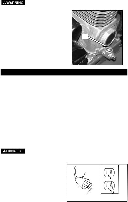
To Add Oil
Drain tank to release air pressure
before removing the oil fill cap or oil drain plug.
1.Place unit on a level surface.
2.Remove oil fill plug (A) and slowly add compressor oil until it is even with the top of the oil fill hole. NOTE: Do not allow oil to be lower than 3/8" (6 threads) from the top at any time. When filling the crankcase, the oil flows very slowly into the pump. If the oil is added too quickly, it will overflow and appear to be full.
NOTE: Crankcase oil capacity is |
|
approximately 16 fluid ounces. |
|
3. |
Replace oil fill plug. |
A
INSTALLATION
Location of the Air Compressor
Locate the air compressor in a clean, dry and well ventilated area. The air compressor should be located at least 12" away from the wall or other obstructions that will interfere with the flow of air. The air compressor pump and shroud are designed to allow for proper cooling. The ventilation openings on the compressor are necessary to maintain proper operating temperature. Do not place rags or other containers on or near these openings.
GROUNDING INSTRUCTIONS
RISK OF ELECTRICAL SHOCK. In the event of a short circuit, grounding reduces the risk of shock by providing an escape wire for the electric current. This air compressor must be properly grounded.
The portable air compressor is equipped with a cord having a grounding wire with an appropriate grounding plug (see following illustrations). The plug must be used with an outlet that has been installed and grounded in accordance with all local codes and ordinances.
1.The cord set and plug with this unit contains a grounding pin. This plug MUST be used with a grounded outlet.
IMPORTANT: The outlet being used must be installed and grounded in accordance with all local codes and ordinances.
2.Make sure the outlet being used has the same configuration
as the grounded plug. DO NOT USE AN ADAPTER. See illustration.
Plug
Grounding Pin
Grounded
Outlets
A09713 |
12ENG |
3.Inspect the plug and cord before each use. Do not use if there are signs of damage.
4.If these grounding instructions are not completely understood, or if in doubt as to whether the compressor is properly grounded, have the installation checked by a qualified electrician.
RISK OF ELECTRICAL
SHOCK. IMPROPER GROUNDING CAN RESULT IN ELECTRICAL SHOCK.
Do not modify the plug provided. If it does not fit the available outlet, a correct outlet should be installed by a qualified electrician.
Repairs to the cord set or plug MUST be made by a qualified electrician.
Extension Cords
Using extension cords is not recommended. The use of extension cords will cause voltage to drop resulting in power loss to the motor and overheating.
Instead of using an extension cord, increase the working reach of the air hose by attaching another length of hose to its end. Attach additional lengths of hose as needed.
If an extension cord must be used, be sure it is:
•a 3-wire extension cord that has a 3-blade grounding plug, and a 3-slot receptacle that will accept the plug on the product
•in good condition
•no longer than 50 feet
•12 gauge (AWG) or larger. (Wire size increases as gauge number decreases. 10 AWG and 8 AWG may also be used. DO NOT USE 14 OR 16 AWG.)
Voltage and Circuit Protection
Refer to the specification chart for the voltage and minimum branch circuit requirements.
Risk of Unsafe Operation. Certain
air compressors can be operated on a 15 amp circuit if the following conditions are met.
1.Voltage supply to circuit must comply with the National Electrical Code.
2.Circuit is not used to supply any other electrical needs.
3.Extension cords comply with specifications.
4.Circuit is equipped with a 15 amp circuit breaker or 15
amp time delay fuse. NOTE: If compressor is connected to a circuit protected by fuses, use only time delay fuses. Time delay fuses should be marked "D" in Canada and "T" in the US.
If any of the above conditions cannot be met, or if operation of the compressor repeatedly causes interruption of the power, it may be necessary to operate it from a 20 amp circuit. It is not necessary to change the cord set.
120/240 Dual Voltage Motor
This model has a dual voltage motor, 120 and 240 volt. It is wired for 120 volt but can be converted to 240 volt operation. Instructions for connecting the motor for operation at 240 volt can be found printed on the label attached to the side of the motor.
When converting to 240V operation, the
attached three-prong 120V cord assembly must be replaced with a three-pronged 240V cord assembly (K-0080) that can be purchased through a Sears Service Center.
|
|
|
120 Volt Plug |
|
240 Volt Plug |
13ENG |
A09713 |
OPERATION
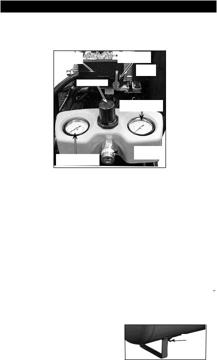
Know Your Air Compressor
READ THIS OWNER’S MANUAL AND SAFETY RULES BEFORE OPERATING YOUR UNIT. Compare the illustrations with your unit to familiarize yourself with the location of various controls and adjustments. Save this manual for future reference.
Pressure
Switch
On/Auto/Off
Switch
Regulator
Safety
 Valve
Valve
Tank
Pressure Gauge
Outlet
Pressure Gauge
Quick
 Connect
On/Auto/Off Switch: Turn this switch "On/Auto" to provide automatic power to the pressure switch and "Off" to remove power at the end of each use.
Pressure Switch: The pressure switch automatically starts the motor when the air tank pressure drops below the factory set "cut-in" pressure. The pressure switch stops the motor when the air tank pressure reaches the factory set "cut-out" pressure.
Safety Valve: If the pressure switch does not shut off the air compressor at its "cut-out" pressure setting, the safety valve will protect against high pressure by "popping out" at its factory set pressure (slightly higher than the pressure switch "cut-out" setting).
Outlet Pressure Gauge: The outlet pressure gauge indicates the air pressure available at the outlet side of the regulator. This pressure is controlled by the regulator and is always less than or equal to the tank pressure.
Tank Pressure Gauge: The tank pressure gauge indicates the reserve air pressure in the tank.
Regulator: Controls the air pressure shown on the outlet pressure gauge. Pull the knob out and turn clockwise to increase pressure
and counterclockwise to decrease pressure. When the desired pressure is reached push knob in to lock in place.
Universal Quick-Connect Body:
The universal quick-connect body accepts the three most popular styles of quick-connect plugs: Industrial, automotive (Tru-flate), and ARO. One hand push-to-connect operation makes connections simple and easy.-
Drain Valve: The drain valve is located at the base of the air tank and is used to drain condensation at the end of each use.
Drain
Valve
A09713 |
14ENG |

Cooling System (not shown): This compressor contains an advanced design cooling system. At the heart of this cooling system is an engineered fan. It is perfectly normal for this fan to blow air through the vent holes
in large amounts. You know that the cooling system is working when air is being expelled.
Air Compressor Pump (not shown):
Compresses air into the air tank. Working air is not available until the compressor has raised the air tank pressure above that required at the air outlet.
Check Valve: When the air compressor is operating, the check valve is "open", allowing compressed air to enter the air tank. When the air compressor reaches "cut-out" pressure, the check valve "closes", allowing air pressure to remain inside the air tank.
Pressure
Release
Valve
Check Valve
Pressure Release Valve: The pressure release valve, located on the side of the pressure switch, is designed to automatically release compressed air from the compressor head and the outlet tube when the air compressor reaches "cut-out" pressure or is shut off. The pressure release valve allows the motor to restart freely. When the motor stops running, air will be heard escaping from this valve for a few seconds. No air should be heard leaking when the motor is running or after unit reaches "cut-out" pressure.
Air Intake Filter (not shown) This filter is designed to clean air coming into the pump. This filter must always be clean and ventilation openings free from obstructions. See "Maintenance".
How to Use Your Unit
How to Stop:
1.Set the On/Auto/Off lever to "Off".
Before First Start-up
Risk of Unsafe Operation. Serious damage may result if the following break-in instructions are not closely followed.
This procedure is required before the air compressor is put into service and when the check valve or a complete compressor pump has been replaced.
Break-in Instructions
1.Make sure the On/Auto/Off lever is in the "Off" position.
NOTE: If quick connect is installed, |
|
pull coupler back until it clicks to |
|
prevent air from escaping through the |
|
quick connect. |
|
2. |
Plug the power cord into the |
|
correct branch circuit receptacle. |
|
(Refer to "Voltage and Circuit |
|
Protection" paragraph in the |
|
"Installation" section of this |
|
manual.) |
3.Open the drain valve fully (counterclockwise) to permit air to escape and prevent air pressure build-up in the air tank during the break-in period.
4.Move the On/Auto/Off lever to "On/Auto" position. The compressor will start.
5.Run the compressor for 20 minutes. Make sure the drain valve is open and there is minimal air pressure build-up in
tank.
15ENG |
A09713 |

6.After 20 minutes, close the drain valve (clockwise). The air receiver will fill to "cut-out" pressure and the motor will stop.
The compressor is now ready for use.
Before Each Start-Up:
1.Place On/Auto/Off lever to "Off".
2.Pull regulator knob out, turn counterclockwise until it stops. Push knob in to lock in place.
3.Attach hose and accessories. NOTE: The hose or accessory will require a quick connect plug if the air outlet is equipped with a quick connect.
Risk of Bursting. Too much air
pressure causes a hazardous risk of bursting. Check the
manufacturer’s maximum pressure rating for air tools and accessories. The regulator outlet pressure must never exceed the maximum pressure rating.
How to Start:
1.Turn the On/Auto/Off lever to "On/Auto" and allow tank pressure to build. Motor will
stop when tank pressure reaches "cut-out" pressure.
2.Pull the regulator knob out and turn clockwise to increase pressure. When the desired
pressure is reached push knob in to lock in place. The compressor is ready for use.
A09713 |
16ENG |

MAINTENANCE
Customer Responsibilities
|
Before |
Daily |
Every |
Every |
Every |
Every |
|
|
or after |
Yearly |
|||||
|
each |
8 |
40 |
||||
|
each |
100 |
160 |
|
|||
|
use |
hours |
hours |
hours |
hours |
|
|
|
use |
|
|||||
|
|
|
|
|
|
|
|
|
|
|
|
|
|
|
|
Check Safety Valve |
● |
|
|
|
|
|
|
|
|
|
|
|
|
|
|
Drain Tank |
|
● |
|
|
|
|
|
|
|
|
|
|
|
|
|
Oil Leaks |
|
|
● |
|
|
|
|
|
|
|
|
|
|
|
|
Check Oil |
|
|
● |
|
|
|
|
|
|
|
|
|
|
|
|
Change Oil |
|
|
|
|
● |
|
|
|
|
|
|
|
|
|
|
Unusual Noise and/ |
|
|
● |
|
|
|
|
or Vibration |
|
|
|
|
|
|
|
|
|
|
|
|
|
|
|
|
|
|
|
|
|
|
|
Air Filter |
|
|
|
● (1) |
|
|
|
|
|
|
|
|
|
|
|
Drive Belt |
|
|
|
● |
|
|
|
Condition |
|
|
|
|
|
|
|
|
|
|
|
|
|
|
|
|
|
|
|
|
|
|
|
Motor Pulley/ |
|
|
|
|
|
● |
|
Flywheel alignment |
|
|
|
|
|
|
|
|
|
|
|
|
|
|
|
|
|
|
|
|
|
|
|
Air compressor pump |
|
|
|
|
|
|
|
intake and exhaust |
|
|
|
|
|
|
● |
valves |
|
|
|
|
|
|
|
|
|
|
|
|
|
|
|
1- more frequent in dusty or humid conditions
Risk of Unsafe
Operation. Unit cycles automatically when power is on. When servicing, you may be exposed to voltage sources, compressed air, or moving parts. Before servicing unit unplug or disconnect electrical supply to the air compressor, bleed tank of pressure, and allow the air compressor to cool.
To ensure efficient operation and longer life of the air compressor air compressor, a routine maintenance schedule should be prepared and followed. The following routine maintenance schedule is geared to an air compressor in a normal
working environment operating on a daily basis. If necessary, the schedule should be modified to suit the conditions under which your compressor is used. The modifications will depend upon the hours of operation and the working environment. Air compressors in an extremely dirty and/or hostile environment will require a greater
frequency of all maintenance checks.
NOTE: See "Operation" section for the location of controls.
17ENG |
A09713 |
 Loading...