


RZ 100 


Installation Instructions:
TO AVOID CONFUSION DURING INSTALLATION follow steps 1 through 5 listed below
Step 1. Remove pages 2 through 7 from book Step 2. Remove your router install pages Step 3. Return extra pages to box
Step 4. For smoothest plunging action purchase STP® before installation. SEE PAGE 2
Step 5. See page 3 for parts diagram
Router Install Pages
Craftsman 27505-27506-27510-27511 -- ( 8-9-10 )
De Walt DW 625 & ELU 3337- 3338-3339 -- ( 11-12-13 )
De Walt DW 621 -- ( 14-15-16 )
Freud FT 2000 -- ( 17-18-19 )
Hitachi M12V -- ( 20-21-22 )
Hitachi TR12 -- ( 23-24-25 )
Makita 3612 Series -- ( 26-27-28-29 )
Porter Cable 6931 Plunge Base -- ( 30-31-32-33-34-35 )
Porter Cable 7538 / 7539 -- ( 36-37-38 )
Porter Cable 7529 / 8529 -- ( 39-40-41 )
Ryobi RE 600 -- ( 42-43-44 )
Ryobi RE 500 -- ( instructions available on our website )
For Parts or Installation Assistance Contact
phone: 1-866-266-1293
INC. |
fax: |
1-515-266-2122 |
|
2729 Delaware Ave, Des Moines, IA. 50317 |
|
|
|
Visit our Website @ |
Porter |
Cable |
|
|
|||
|
/ |
||
www.routertechnologies.com |
7538 |
|
7539 |
|
|
||
|
|
|
|
© 2000-2005 Router Technologies |
|
|
3 |
All Rights Reserved |
|
|
|
|
|
|
2 |
|
|
|
1 |
Craftsman is a registered trademark of the Sears, Roebuck and Co. Corporation |
|
|
|
DeWalt is a registered trademark of the Black and Decker Corporation |
|
|
|
ELU is a registered trademark of the A.G. Corporation |
|
|
|
Freud is a registered trademark of Freud USA Ltd |
|
|
|
Hitachi is a registered trademark of the Hitachi Ltd Corporation |
|
|
|
Makita is a registered trademark of the Makita Electric Works Corporation |
|
|
|
Porter Cable is a registered trademark of the Porter Cable Corporation |
|
|
|
Ryobi is a registered trademark of the Ryobi Ltd Corporation |
|
|
|
Craftsman |
|
|
DeWalt |
||||
|
|
|
|
DW |
625 |
||
|
|
|
|
|
|
||
DeWalt |
|
|
Freud |
|
|||
DW |
621 |
|
|
FT |
2000 |
||
|
|
|
|
|
|
||
Hitachi |
|
|
Hitachi |
||||
M12V |
|
|
TR12 |
|
|||
Makita |
|
|
Porter |
Cable |
|||
3612 |
|
|
|
||||
|
|
|
|
6931 |
|||
Porter |
7529 |
/ 8529 |
Ryobi |
|
|||
Cable |
|
RE |
600 |
||||
|
|
||||||
|
|
|
|
|
|||

Page 1 |
METRIC EQUIVILANTS FOR INTERNATIONAL CUSTOMERS |
|
|
Note: The following metric drill bit or wrench sizes may be substituted |
|
|
for all operations other than drilling hole for #30 Dust Cover Insert. |
|
|
1/8” = 0.125" |
3.20mm = 0.126" |
|
3/32" = 0.093 |
2.4mm = 0.094 |
|
5/32" = 0.156" |
no metric equivilant, this hole must be drilled to 5/32" |
|
7/32" = 0.218" |
5.5mm = 0.216" |
|
5/16" = 0.312" |
8.0mm = 0.315 |
|
21/64" = 0.328" |
8.3mm = 0.326" or 8.5mm = 0.334" |
|
1/2" = 0.500" |
12.8mm = 0.503 or 13mm = 0.511 |
|
11/16"= 0.687" |
17.5mm = 0.689" or 18mm = 0.708" |
|
3/4" = 0.750" |
19.0mm = 0.748 |
|
# 30 Dust Cover Insert must be 0.500" use a 12.5mm bit |
|
|
and sand hole to fit cover. 12.5mm = 0.492" |
|
This instruction manual covers several different makes and models of plunge routers. The instructions are written for a person with some mechanical ability. If you understand the parts and operation of a plunge router, installing the Router Raizer is not difficult. Before beginning installation compare the illustrations and photos to your router, original subbase or router table insert plate. Understand the location and function of both original and Router Raizer parts. Keep all spare parts, instruction manual and templates for future reference.
Responsibility of the Owner
Important: Read, understand and follow instructions to avoid personal injury.
1.The responsibility of the owner is to follow the instructions, cautions, and warnings bellow and in the instructions
2.Know and understand the location of both original and Router Raizer parts.
3.Follow all the assembly instructions carefully.
4.Correctly adjust the components making sure the plunge action is smooth and plunge lock operates properly.
5.Carefully read and follow all notes, tips, cautions and warnings.
6.Make sure all operators of the Router Raizer know how to correctly use it.
Caution: Before and during installation of Router Raizer make sure power switch is in the off position and tool is disconnected from power source to avoid accidental starting of the tool which may result in personal injury.
Caution: Always make sure router power switch is in the off position and disconnected from power source before and during any adjustments to the router or Router Raizer.
Warning: Never remove or reinstall #31 dust cover or make any depth of cut adjustments from either end of
#1 mainshaft until router power switch is off, cutting tool has completely stopped rotating and tool is disconnected from power source.
Caution: Always secure plunge lock before and during routing operations.
ROUTER TECHNOLOGIES LIMITED TWO YEAR WARRANTY
Router Technologies warrants the Router Raizer to be free from defects in material and workmanship for a period of Two ( 2 ) Years from the original date of purchase to original owner. Our responsibility under this warranty is to replace, at no cost, any part which upon inspection at our facility is found to be defective in either material or workmanship. This warranty does not imply that the product is fit for a particular use or application, this warranty does not apply to parts which have been modified, altered, misused, damaged by improper storage. It also does not cover loss of parts during use, or mechanical adjustments which are covered in the instruction manual. In no event shall Router - Technologies be liable for any indirect, incidental or consequential damages from the sale or use of the product. This disclaimer applies both during and after the term of the warranty.
This warranty is your only remedy and parts are to be returned prepaid to our facility for inspection at Router Technologies, 2729 Delaware Ave, Des Moines, IA. 50317.
This warranty gives you specific legal rights, and you may have other rights which may vary from state to state. Any legal actions must be brought in Polk County Iowa.
© 2000-2005 Router Technologies
All Rights Reserved
READ THIS PAGE BEFORE INSTALLATION |
Page 2 |
|
FULL SIZE PARTS DIAGRAM ON BACK OF THIS PAGE ( PAGE 3 )
1. Remove Pages From Book
Before installation please remove the pages required for your router from this book.
Failure to due so can result in referring to the wrong page, confusion and damaged parts!
2. Installation
The Router Raizer is designed to make the plunge router easy and enjoyable to adjust . It may appear to be complex and difficult to install, but the plunge router is an easy tool to disassemble and reassemble. Allow approximately 11/2 hours for installation. For technical assistance call toll free 1-866-266-1293
3. Multiple Parts ( After installation you will have extra parts )
The Router Raizer is a universal kit containing many parts you will not install into your router. Each instruction page lists the parts required for installation into that router. We advise keeping and storing all the extra parts and instructions.
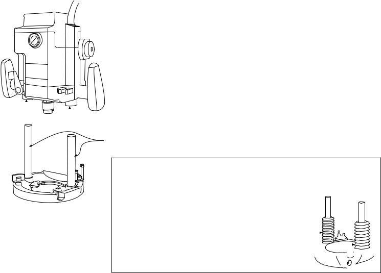
4. STP® for Lubricating The Plunging Action ( All Plunge Routers )
For maximum performance and smoothest plunging action all plunge posts require
a light film of lubrication. We only recommend using STP® MOTOR OIL TREATMENT.
Before beginning the installation please purchase a bottle of STP®. Apply a light film to the posts and inside the post bushings just before reassembling the router.
1. Install the Router Raizer components into the base and motor housing of the router.
2. Before reinstalling the motor housing onto the base, use a Q tip, brush or little finger to apply a film of STP® to the inside of both post bushings and the outside of both plunge posts.
NOTE: STP® on the posts can attract dust, but the lubricating properties are not affected. periodically wiping the posts clean and reapplying STP® to the posts only will keep the router operating smoothly.
 Post Bushings
Plunge Posts
Apply light film on the inside surface of both post bushings.
Apply light film to the outside surface of both plunge posts.
© 2000-2005 Router Technologies
All Rights Reserved
5. Plunge Post Boots
Some plunge routers use rubber boots to seal the posts from dust and debris.
We recommend leaving these boots off when reassembling the router, and using the above lubrication and maintenance to keep the router operating smoothly.
Plunge Post Boots 


To avoid confusion during installation remove this page and router being installed pages, return others to box.
Note; Actual mainshaft length 12 1/4" |
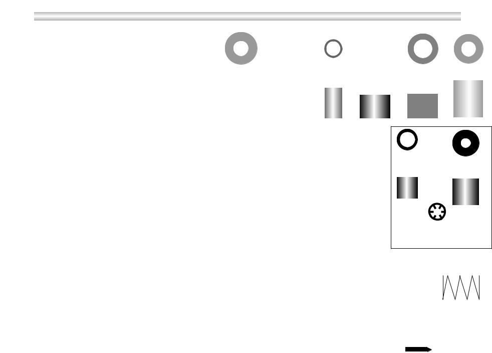
RZ 100 Parts Diagram |
Parts Shown Full Size |
|
|
|
|
|
|
|
|
|
#1 Mainshaft |
|
|
|
|
|
|
|
|
|
|
|
|
|
|
|
|
|
|
|
|
|
|
|
|
|
|
|
|
|
|
|
|
|
|
|
|
|
|
|
|
|
|
|
|
|
|
|
|
|
|
|
|
|
|
|
|
|
||
#2 Long Green Drive Pin |
|
|
|
|
|
|
|
|
|
|
|
|
|
|
|
|
|
|
|
|
|
|
|
|
|
|
|
|
|
#4 Green Rollpins |
#5 Red Rollpins #6 Yellow Rollpins #7 Brass Washer #8 White Nylon |
#9 Red Nylon |
#10 Black Nylon |
#11 Blue Nylon |
#12 Green Nylon |
||||||||||||||||||||||||
|
|||||||||||||||||||||||||||||
#3 Long Red Drive Pin |
|
|
|
|
|
|
|
|
|
|
|
|
|
|
|
|
|
|
|
|
|
|
|
Flanged Bushing |
Bushing |
Bushing |
Bushing |
Bushing |
|
|
|
|
|
|
|
|
|
|
|
|
|
|
|
|
|
|
|
|
|
|
|
|
|
|
|
|
|
||
|
|
|
|
|
|
|
|
|
|
|
|
|
|
|
|
|
|
|
|
|
|
|
|
|
|
|
|
|
|
|
|
|
|
|
|
|
|
|
|
|
|
|
|
|
|
|
|
|
|
|
|
|
|
|
|
|
|
|
|
|
|
#14 Steel |
#15 Retainer |
#13 Hollow Spring Guide |
|
six included |
|
|
3/16" Washer |
three required |
|
|
three extra
#32 Purple Nylon |
#34 Orange Nylon |
|
Bushing |
||
Bushing |
||
|
|
|
#17 housing |
#18 Drive Nut |
#26 Top Drive |
#27 Yellow |
|
|
|
Set Screw ( 10 / 32 ) |
||||
#16 |
Housing |
Bushing Washer |
Washer |
|||
|
|
|||||
|
|
|
|
|||
Bushing |
|
|
|
|
||
Top |
|
|
View |
|
|
|
#33 Yellow Retainer |
|
Side |
two included |
|
one required |
||
View |
||
one extra |
||
|
Technologies Router 2005-2000 © Reserved Rights All
#22 Rapid |
#23 Rubber |
Collar |
O-ring |
#28 Allen Wrench
#19 Short |
#20 Long |
|
Drive Nut |
Drive Nut |
#21 Lead Screw |
|
|
Magnet
#29 Speed Wrench
#24 Thumb |
#25 Optional Black |
||||
Screw |
Set Screw ( 10 / 32 ) |
||||
|
|
|
|
|
|
|
|
|
|
|
|
|
|
|
|
|
|
#35 Plunge Lock Spring
Porter Cable Only
#30 Dust Cover |
#31 Dust Cover |
Insert |
Two Included |
3 Page
Caution: Before and during installation of Router Raizer make sure power switch is in the off position and tool is |
|
|
|
|
|
|
|
|
|
|
|
#46 Allan Screw Locating Pin |
||
disconnected from power source to avoid accidental starting of the tool which may result in personal injury. |
© 2002 Router Technologies |
|
||
|
|
|
|
|
 Loading...