


 Loading...
Service Manual
Nellcor™
Bedside Respiratory Patient Monitoring System
COVIDIEN, COVIDIEN with logo, the Covidien logo and positive results for life are U.S. and internationally registered trademarks of Covidien AG. Other brands are trademarks of a Covidien company.
©2013 Covidien. All rights reserved.
Microsoft and Windows EC are registered trademarks of Microsoft Corporation in the United States and other countries.
The information contained in this manual is the sole property of Covidien and may not be duplicated without permission. This manual may be revised or replaced by Covidien at any time and without notice. It is the responsibility of the reader to have the most current applicable version of this manual. If in doubt, contact Covidien Technical Services.
While the information set forth herein is believed to be accurate, it is not a substitute for the exercise of professional judgment.
The equipment and software should only be operated and serviced by trained professionals. Covidien’s sole responsibility with respect to the equipment and software, and its use, is as stated in the limited warranty provided.
Nothing in this manual shall limit or restrict in any way Covidien’s right to revise or otherwise change or modify the equipment and software described herein, without notice. In the absence of an express, written agreement to the contrary, Covidien has no obligation to furnish any such revisions, changes, or modifications to the owner or user of the equipment and software described herein.

Table of Contents
1Introduction
1.1 |
Overview . . . . . . . . . . . . . . . . . . . . . . . . . . . . . . . . . . . . . . |
1-1 |
1.2 |
Intended Audience . . . . . . . . . . . . . . . . . . . . . . . . . . . . . . |
1-1 |
1.3 |
Safety Information . . . . . . . . . . . . . . . . . . . . . . . . . . . . . . |
1-2 |
1.3.1 |
Safety Symbols . . . . . . . . . . . . . . . . . . . . . . . . . . . . . . . . . . . |
1-2 |
1.3.2 |
Warnings . . . . . . . . . . . . . . . . . . . . . . . . . . . . . . . . . . . . . . . |
1-2 |
1.3.3 |
Cautions . . . . . . . . . . . . . . . . . . . . . . . . . . . . . . . . . . . . . . . . |
1-4 |
1.4 |
Obtaining Technical Assistance . . . . . . . . . . . . . . . . . . . . |
1-5 |
1.4.1 |
Technical Services . . . . . . . . . . . . . . . . . . . . . . . . . . . . . . . . . |
1-5 |
1.4.2 |
On-Screen Help . . . . . . . . . . . . . . . . . . . . . . . . . . . . . . . . . . |
1-6 |
1.5 |
Related Documents . . . . . . . . . . . . . . . . . . . . . . . . . . . . . . |
1-6 |
1.6 |
Warranty Information . . . . . . . . . . . . . . . . . . . . . . . . . . . . |
1-6 |
2Product Specifications
2.1 |
Overview . . . . . . . . . . . . . . . . . . . . . . . . . . . . . . . . . . . . . |
. 2-1 |
2.2 |
Physical Characteristics . . . . . . . . . . . . . . . . . . . . . . . . . . |
. 2-1 |
2.3 |
Electrical Requirements . . . . . . . . . . . . . . . . . . . . . . . . . . |
. 2-1 |
2.3.1 |
Power . . . . . . . . . . . . . . . . . . . . . . . . . . . . . . . . . . . . . . . . . |
. 2-1 |
2.3.2 |
Battery . . . . . . . . . . . . . . . . . . . . . . . . . . . . . . . . . . . . . . . . |
. 2-2 |
2.3.3 Rating of Nurse Call Relay . . . . . . . . . . . . . . . . . . . . . . . . . . |
. 2-2 |
|
2.4 |
Environmental Conditions . . . . . . . . . . . . . . . . . . . . . . . |
. 2-3 |
2.4.1 |
Operating . . . . . . . . . . . . . . . . . . . . . . . . . . . . . . . . . . . . . . |
. 2-3 |
2.4.2 |
Transport and Storage . . . . . . . . . . . . . . . . . . . . . . . . . . . . |
. 2-3 |
2.5 |
Sensor Accuracy and Ranges . . . . . . . . . . . . . . . . . . . . . |
. 2-4 |
2.6 |
Sound Pressure . . . . . . . . . . . . . . . . . . . . . . . . . . . . . . . . |
. 2-5 |
2.7 |
Product Compliance . . . . . . . . . . . . . . . . . . . . . . . . . . . . . |
. 2-5 |
2.8 |
Manufacturer’s Declaration and Guidance . . . . . . . . . . |
. 2-6 |
2.8.1 |
Electromagnetic Compatibility (EMC) . . . . . . . . . . . . . . . . . |
. 2-6 |
2.8.2 |
Ground Integrity . . . . . . . . . . . . . . . . . . . . . . . . . . . . . . . . . |
2-12 |
2.8.3 |
Safety Tests . . . . . . . . . . . . . . . . . . . . . . . . . . . . . . . . . . . . |
2-12 |
3Theory of Operations
3.1 |
Overview . . . . . . . . . . . . . . . . . . . . . . . . . . . . . . . . . . . . . . |
3-1 |
3.2 |
Block Diagram . . . . . . . . . . . . . . . . . . . . . . . . . . . . . . . . . . |
3-1 |
3.3 |
Theoretical Principles . . . . . . . . . . . . . . . . . . . . . . . . . . . . . |
3-2 |
3.4 |
Automatic Calibration . . . . . . . . . . . . . . . . . . . . . . . . . . . . |
3-3 |
Service Manual |
i |

3.5 |
Functional Testers and Patient Simulators . . . . . . . . . . |
. 3-3 |
3.6 |
Unique Technologies . . . . . . . . . . . . . . . . . . . . . . . . . . . . |
. 3-4 |
3.6.1 Functional versus Fractional Saturation . . . . . . . . . . . . . . . . |
. 3-4 |
|
3.6.2 Measured versus Calculated Saturation . . . . . . . . . . . . . . . . |
. 3-4 |
|
3.6.3 Data Update Period, Data Averaging, and Signal Processing |
. 3-5 |
|
3.7 |
System Features . . . . . . . . . . . . . . . . . . . . . . . . . . . . . . . . |
. 3-6 |
3.7.1 |
Nellcor™ Sensor Technology . . . . . . . . . . . . . . . . . . . . . . . |
. 3-6 |
3.7.2 SatSeconds™ Alarm Management Parameter . . . . . . . . . . . |
. 3-7 |
|
3.7.3 OxiMax SPD™ Alert Parameter . . . . . . . . . . . . . . . . . . . . . . |
3-11 |
|
3.7.4 Pulse Rate Delay Alarm Management Parameter . . . . . . . . . |
3-13 |
|
4Product Overview
4.1 |
Overview . . . . . . . . . . . . . . . . . . . . . . . . . . . . . . . . . . . . . . |
4-1 |
4.2 |
Product Description . . . . . . . . . . . . . . . . . . . . . . . . . . . . . . |
4-1 |
4.3 |
Indications for Use . . . . . . . . . . . . . . . . . . . . . . . . . . . . . . . |
4-1 |
4.4 |
List of Components . . . . . . . . . . . . . . . . . . . . . . . . . . . . . . |
4-2 |
4.5 |
Synopsis . . . . . . . . . . . . . . . . . . . . . . . . . . . . . . . . . . . . . . . |
4-2 |
4.6 |
Product Views . . . . . . . . . . . . . . . . . . . . . . . . . . . . . . . . . . |
4-3 |
4.6.1 |
Front Panel . . . . . . . . . . . . . . . . . . . . . . . . . . . . . . . . . . . . . . |
4-3 |
4.6.2 |
Monitoring Screen . . . . . . . . . . . . . . . . . . . . . . . . . . . . . . . . |
4-4 |
4.6.3 |
Rear Panel . . . . . . . . . . . . . . . . . . . . . . . . . . . . . . . . . . . . . . |
4-6 |
4.7 |
Labeling Symbology . . . . . . . . . . . . . . . . . . . . . . . . . . . . . |
4-7 |
5Installation
5.1 |
Overview . . . . . . . . . . . . . . . . . . . . . . . . . . . . . . . . . . . . . . |
5-1 |
5.2 |
Safety Reminders . . . . . . . . . . . . . . . . . . . . . . . . . . . . . . . . |
5-1 |
5.3 |
Product Setup . . . . . . . . . . . . . . . . . . . . . . . . . . . . . . . . . . . |
5-3 |
5.3.1 Mounting Options and Transport Considerations . . . . . . . . . |
5-3 |
|
5.3.2 Connection to an AC Power Source . . . . . . . . . . . . . . . . . . . |
5-3 |
|
5.3.3 |
Battery Insertion . . . . . . . . . . . . . . . . . . . . . . . . . . . . . . . . . . |
5-4 |
5.3.4 |
Battery Charge . . . . . . . . . . . . . . . . . . . . . . . . . . . . . . . . . . . |
5-5 |
5.3.5 |
Battery Power Usage . . . . . . . . . . . . . . . . . . . . . . . . . . . . . . . |
5-6 |
5.4 |
Connection to Nellcor™ Sensors . . . . . . . . . . . . . . . . . . . |
5-7 |
6Operation
6.1 |
Overview . . . . . . . . . . . . . . . . . . . . . . . . . . . . . . . . . . . . . . |
6-1 |
6.2 |
Power . . . . . . . . . . . . . . . . . . . . . . . . . . . . . . . . . . . . . . . . . |
6-1 |
6.2.1 |
AC Power . . . . . . . . . . . . . . . . . . . . . . . . . . . . . . . . . . . . . . . |
6-2 |
ii |
Service Manual |

6.2.2 |
Battery Power . . . . . . . . . . . . . . . . . . . . . . . . . . . . . . . . . . . |
. 6-2 |
6.2.3 |
Power Up . . . . . . . . . . . . . . . . . . . . . . . . . . . . . . . . . . . . . . |
. 6-4 |
6.2.4 |
System Resets . . . . . . . . . . . . . . . . . . . . . . . . . . . . . . . . . . . |
. 6-6 |
6.2.5 Automatic Shutdown and Power Off . . . . . . . . . . . . . . . . . |
. 6-6 |
|
6.3 |
Nellcor™ Sensor Usage . . . . . . . . . . . . . . . . . . . . . . . . . . |
. 6-7 |
6.3.1 |
Sensor Detection . . . . . . . . . . . . . . . . . . . . . . . . . . . . . . . . |
. 6-7 |
6.3.2 |
Sensor Detection Failure . . . . . . . . . . . . . . . . . . . . . . . . . . . |
. 6-8 |
6.4 |
User Interface . . . . . . . . . . . . . . . . . . . . . . . . . . . . . . . . . . |
. 6-9 |
6.4.1 Default Monitoring Screen and Trend Data . . . . . . . . . . . . . |
. 6-9 |
|
6.4.2 Status Messages and Alarms in the Monitoring Status Field |
. 6-9 |
|
6.4.3 Alarm Management and Status Messages . . . . . . . . . . . . . . |
6-10 |
|
6.4.4 |
Audible Alarm Management . . . . . . . . . . . . . . . . . . . . . . . . |
6-13 |
6.4.5 |
Visual Alarm Management . . . . . . . . . . . . . . . . . . . . . . . . . |
6-15 |
6.4.6 |
HELP Option . . . . . . . . . . . . . . . . . . . . . . . . . . . . . . . . . . . . |
6-16 |
6.5 |
Service Mode . . . . . . . . . . . . . . . . . . . . . . . . . . . . . . . . . . |
6-16 |
6.5.1 |
Settings Menu . . . . . . . . . . . . . . . . . . . . . . . . . . . . . . . . . . |
6-19 |
6.5.2 |
Service Menu . . . . . . . . . . . . . . . . . . . . . . . . . . . . . . . . . . . |
6-31 |
6.5.3 |
Logs Menu . . . . . . . . . . . . . . . . . . . . . . . . . . . . . . . . . . . . . |
6-31 |
6.5.4 |
Covidien Service Menu . . . . . . . . . . . . . . . . . . . . . . . . . . . . |
6-32 |
6.5.5 |
Parameter Activation Menu . . . . . . . . . . . . . . . . . . . . . . . . |
6-33 |
6.5.6 |
About Monitor Menu . . . . . . . . . . . . . . . . . . . . . . . . . . . . . |
6-33 |
7Trend Data Access
7.1 |
Overview . . . . . . . . . . . . . . . . . . . . . . . . . . . . . . . . . . . . . |
. 7-1 |
7.2 |
Trend Data Management . . . . . . . . . . . . . . . . . . . . . . . . |
. 7-1 |
7.2.1 |
Trend Data Basics . . . . . . . . . . . . . . . . . . . . . . . . . . . . . . . . |
. 7-1 |
7.3 |
Data Port Connectivity . . . . . . . . . . . . . . . . . . . . . . . . . . |
. 7-2 |
7.3.1 |
Overview . . . . . . . . . . . . . . . . . . . . . . . . . . . . . . . . . . . . . . |
. 7-2 |
7.3.2 Typical Equipment Used for Connectivity . . . . . . . . . . . . . . |
. 7-3 |
|
7.3.3 Data Port Configuration Information . . . . . . . . . . . . . . . . . . |
. 7-3 |
|
7.3.4 |
Data Port Communications . . . . . . . . . . . . . . . . . . . . . . . . . |
7-14 |
7.4 |
Using the Nurse Call Interface . . . . . . . . . . . . . . . . . . . . |
7-14 |
7.4.1 |
Nurse Call Feature . . . . . . . . . . . . . . . . . . . . . . . . . . . . . . . |
7-14 |
7.4.2 Setting Nurse Call RS-232 Polarity . . . . . . . . . . . . . . . . . . . . |
7-16 |
|
7.5 |
Calculating the Analog Voltage Output . . . . . . . . . . . . |
7-17 |
8Performance Considerations
8.1 |
Overview . . . . . . . . . . . . . . . . . . . . . . . . . . . . . . . . . . . . . . |
8-1 |
8.2 |
Oximetry Considerations . . . . . . . . . . . . . . . . . . . . . . . . . |
8-1 |
Service Manual |
iii |

8.2.1 |
Monitoring System Constraints . . . . . . . . . . . . . . . . . . . . . . . |
8-1 |
8.2.2 Nellcor™ Sensor Performance Considerations . . . . . . . . . . . . |
8-1 |
|
8.3 |
Patient Conditions . . . . . . . . . . . . . . . . . . . . . . . . . . . . . . . |
8-3 |
8.4 |
Reducing EMI (Electromagnetic Interference) . . . . . . . . . |
8-4 |
9Product Maintenance
9.1 |
Overview . . . . . . . . . . . . . . . . . . . . . . . . . . . . . . . . . . . . |
. . 9-1 |
9.2 |
Cleaning . . . . . . . . . . . . . . . . . . . . . . . . . . . . . . . . . . . . . |
. . 9-1 |
9.3 |
Periodic Safety Checks . . . . . . . . . . . . . . . . . . . . . . . . . . |
. . 9-1 |
9.4 |
Service and Upgrades . . . . . . . . . . . . . . . . . . . . . . . . . . |
. . 9-2 |
9.5 |
Storage . . . . . . . . . . . . . . . . . . . . . . . . . . . . . . . . . . . . . . |
. . 9-2 |
9.5.1 |
Monitoring System Transport and Storage . . . . . . . . . . . . |
. . 9-2 |
9.5.2 |
Removed Battery Storage . . . . . . . . . . . . . . . . . . . . . . . . . |
. . 9-2 |
10 |
Modification and Testing |
|
10.1 |
Overview . . . . . . . . . . . . . . . . . . . . . . . . . . . . . . . . . . . . |
. 10-1 |
10.2 |
Setting Institutional Defaults . . . . . . . . . . . . . . . . . . . . |
. 10-5 |
10.3 |
Performance Verification . . . . . . . . . . . . . . . . . . . . . . . |
. 10-8 |
10.3.1 Overview . . . . . . . . . . . . . . . . . . . . . . . . . . . . . . . . . . . . . |
. 10-8 |
|
10.3.2 Required Equipment . . . . . . . . . . . . . . . . . . . . . . . . . . . . . |
. 10-8 |
|
10.4 |
Safety Testing Standards . . . . . . . . . . . . . . . . . . . . . . . |
. 10-9 |
10.5 |
Battery Check . . . . . . . . . . . . . . . . . . . . . . . . . . . . . . . . . |
10-10 |
10.5.1 Battery Power . . . . . . . . . . . . . . . . . . . . . . . . . . . . . . . . . . |
10-10 |
|
10.5.2 Battery Charge . . . . . . . . . . . . . . . . . . . . . . . . . . . . . . . . . |
10-10 |
|
10.6 |
Performance Tests . . . . . . . . . . . . . . . . . . . . . . . . . . . . . |
10-11 |
10.6.1 Power-On Defaults and Alarm Ranges . . . . . . . . . . . . . . . |
10-11 |
|
10.6.2 Operational Setup . . . . . . . . . . . . . . . . . . . . . . . . . . . . . . . |
10-17 |
|
10.6.3 Overall Performance Check . . . . . . . . . . . . . . . . . . . . . . . . |
10-22 |
|
10.6.4 Pulse Oximetry Functional Tests . . . . . . . . . . . . . . . . . . . . |
10-24 |
|
10.6.5 Setting Nurse Call . . . . . . . . . . . . . . . . . . . . . . . . . . . . . . . |
10-40 |
|
10.7 |
Test Data Sheet Form . . . . . . . . . . . . . . . . . . . . . . . . . . |
10-42 |
10.8 |
Monitoring Screen Calibration . . . . . . . . . . . . . . . . . . . |
10-44 |
10.9 |
Software and Firmware Upgrades . . . . . . . . . . . . . . . . |
10-45 |
11 |
Troubleshooting |
|
11.1 |
Overview . . . . . . . . . . . . . . . . . . . . . . . . . . . . . . . . . . . . |
. 11-1 |
11.2 |
System Condition Categories . . . . . . . . . . . . . . . . . . . . |
. 11-1 |
11.3 |
User Prompts and Messages . . . . . . . . . . . . . . . . . . . . . |
. 11-4 |
iv |
Service Manual |

11.4 |
Alarms and Error Conditions . . . . . . . . . . . . . . . . . . . . . |
. 11-4 |
11.4.1 Alarms . . . . . . . . . . . . . . . . . . . . . . . . . . . . . . . . . . . . . . . |
. 11-4 |
|
11.4.2 Correctable error conditions . . . . . . . . . . . . . . . . . . . . . . . |
. 11-9 |
|
11.5 |
Power Failure Issues . . . . . . . . . . . . . . . . . . . . . . . . . . . |
11-11 |
11.6 |
Monitoring Screen Issues . . . . . . . . . . . . . . . . . . . . . . . |
11-13 |
11.7 |
Alarm Issues . . . . . . . . . . . . . . . . . . . . . . . . . . . . . . . . . . |
11-14 |
11.8 |
Communication Issues . . . . . . . . . . . . . . . . . . . . . . . . . . |
11-16 |
11.9 |
Operational Performance Issues . . . . . . . . . . . . . . . . . . |
11-17 |
11.10 |
Hardware Issues . . . . . . . . . . . . . . . . . . . . . . . . . . . . . . . |
11-17 |
11.11 |
System Errors and Software issues . . . . . . . . . . . . . . . |
11-19 |
11.12 |
Non-correctable Failures . . . . . . . . . . . . . . . . . . . . . . . . |
11-19 |
11.13 |
Product Return . . . . . . . . . . . . . . . . . . . . . . . . . . . . . . . . |
11-20 |
12 |
Repair |
|
12.1 |
Overview . . . . . . . . . . . . . . . . . . . . . . . . . . . . . . . . . . . . |
. 12-1 |
12.2 |
Spare Parts List . . . . . . . . . . . . . . . . . . . . . . . . . . . . . . . . |
. 12-1 |
12.3 |
Repair Prerequisites and Required Equipment . . . . . . |
. 12-5 |
12.4 |
Basic Preventive Maintenance . . . . . . . . . . . . . . . . . . . |
. 12-6 |
12.4.1 Fuse Removal and Replacement . . . . . . . . . . . . . . . . . . . . |
. 12-7 |
|
12.4.2 Battery or Battery Access Door Replacement . . . . . . . . . . . |
. 12-7 |
|
12.4.3 Rubber Feet Replacement . . . . . . . . . . . . . . . . . . . . . . . . . |
. 12-8 |
|
12.5 |
Chassis Disassembly and Reassembly . . . . . . . . . . . . . |
12-10 |
12.5.1 Parameter Module Replacement . . . . . . . . . . . . . . . . . . . . |
12-10 |
|
12.5.2 Monitoring System Chassis Disassembly . . . . . . . . . . . . . . |
12-17 |
|
12.5.3 Monitoring System Chassis Reassembly . . . . . . . . . . . . . . . |
12-20 |
|
12.6 |
Power Components Replacement . . . . . . . . . . . . . . . . |
12-21 |
12.6.1 Power Entry Module (PEM) Replacement . . . . . . . . . . . . . . |
12-22 |
|
12.6.2 Right Power Cable Assembly Replacement . . . . . . . . . . . . |
12-22 |
|
12.6.3 Battery Components Replacement . . . . . . . . . . . . . . . . . . |
12-24 |
|
12.6.4 Left Power Cable Assembly Replacement . . . . . . . . . . . . . |
12-31 |
|
12.7 |
Front Panel Components Replacement . . . . . . . . . . . . |
12-32 |
12.7.1 Main PCB Components Replacement . . . . . . . . . . . . . . . . |
12-33 |
|
12.7.2 LCD Assembly with Overlay Replacement . . . . . . . . . . . . . |
12-39 |
|
12.8 |
Return Authorization and Shipment . . . . . . . . . . . . . . |
12-41 |
12.8.1 General Instructions for Return . . . . . . . . . . . . . . . . . . . . . |
12-41 |
|
12.8.2 Repackage in Original Carton . . . . . . . . . . . . . . . . . . . . . . |
12-42 |
|
12.8.3 Repackage in an Alternate Carton . . . . . . . . . . . . . . . . . . |
12-43 |
|
Index
Service Manual |
v |

Page Left Intentionally Blank
vi

List of Tables
Table 1-1. Safety Symbol Definitions . . . . . . . . . . . . . . . . . . . . . . . . . . . . . . . . . . . 1-2 Table 2-1. Nellcor™ Sensor Accuracy and Ranges . . . . . . . . . . . . . . . . . . . . . . . 2-4 Table 2-2. Nellcor™ Sensor Operating Range and Power Dissipation. . . . . 2-5 Table 2-3. Sound Pressure in Decibels . . . . . . . . . . . . . . . . . . . . . . . . . . . . . . . . . . 2-5 Table 2-4. Frequency Band, Output Power, and Modulation Type . . . . . . . 2-6 Table 2-5. Electromagnetic Emissions Guidelines and Compliance . . . . . . 2-7 Table 2-6. Electromagnetic Immunity Guidelines and Compliance . . . . . . 2-8 Table 2-7. Recommended Separation Distance Calculations . . . . . . . . . . . . 2-9 Table 2-8. Recommended Separation Distances . . . . . . . . . . . . . . . . . . . . . . . 2-10
Table 2-9. Sensor and Cable Length . . . . . . . . . . . . . . . . . . . . . . . . . . . . . . . . . . . 2-11
Table 2-10. Earth and Enclosure Leakage Current Specifications . . . . . . . . . 2-12 Table 2-11. Patient Applied and Patient Isolation Risk Current . . . . . . . . . . . 2-13 Table 4-1. Typical Packing List . . . . . . . . . . . . . . . . . . . . . . . . . . . . . . . . . . . . . . . . . 4-2 Table 4-2. Labeling Symbols and Descriptions . . . . . . . . . . . . . . . . . . . . . . . . . . 4-7 Table 6-1. Battery Power Status . . . . . . . . . . . . . . . . . . . . . . . . . . . . . . . . . . . . . . . . 6-3 Table 6-2. Possible User Interface Settings. . . . . . . . . . . . . . . . . . . . . . . . . . . . . 6-16 Table 6-3. Possible Alarm Management Settings. . . . . . . . . . . . . . . . . . . . . . . 6-17 Table 6-4. Possible Data Interface Settings . . . . . . . . . . . . . . . . . . . . . . . . . . . . 6-18 Table 6-5. Possible Service Functions. . . . . . . . . . . . . . . . . . . . . . . . . . . . . . . . . . 6-18 Table 7-1. Input and Output Configuration Options . . . . . . . . . . . . . . . . . . . . 7-2 Table 7-2. Sample Equipment Types . . . . . . . . . . . . . . . . . . . . . . . . . . . . . . . . . . . 7-3 Table 7-3. DB-15 Signal Pinouts . . . . . . . . . . . . . . . . . . . . . . . . . . . . . . . . . . . . . . . . 7-5 Table 7-4. RJ-45 Signal Pinouts. . . . . . . . . . . . . . . . . . . . . . . . . . . . . . . . . . . . . . . . . 7-7 Table 7-5. USB Signal Pinouts . . . . . . . . . . . . . . . . . . . . . . . . . . . . . . . . . . . . . . . . . . 7-8 Table 7-6. Network Configuration Icons . . . . . . . . . . . . . . . . . . . . . . . . . . . . . . . . 7-9 Table 7-7. Nurse Call Relay Pin States. . . . . . . . . . . . . . . . . . . . . . . . . . . . . . . . . . 7-15 Table 7-8. Analog Pinouts. . . . . . . . . . . . . . . . . . . . . . . . . . . . . . . . . . . . . . . . . . . . . 7-17 Table 10-1. Possible User Interface Settings. . . . . . . . . . . . . . . . . . . . . . . . . . . . . 10-2 Table 10-2. Possible Alarm Management Settings. . . . . . . . . . . . . . . . . . . . . . . 10-3 Table 10-3. Possible Data Interface and Service Settings . . . . . . . . . . . . . . . . 10-4 Table 10-4. Equipment and Descriptions . . . . . . . . . . . . . . . . . . . . . . . . . . . . . . . 10-8 Table 10-5. Functional Tests Options . . . . . . . . . . . . . . . . . . . . . . . . . . . . . . . . . .10-26 Table 10-6. Performance and Functional Tests . . . . . . . . . . . . . . . . . . . . . . . . .10-42 Table 10-7. Electrical Safety Tests. . . . . . . . . . . . . . . . . . . . . . . . . . . . . . . . . . . . . .10-43 Table 11-1. Common User Prompts and Messages . . . . . . . . . . . . . . . . . . . . . . 11-4 Table 11-2. Initial Alarm Priority for Errors . . . . . . . . . . . . . . . . . . . . . . . . . . . . . . 11-5 Table 11-3. Common Correctable Problems and Resolutions . . . . . . . . . . . . 11-9 Table 11-4. Power Failure Issues. . . . . . . . . . . . . . . . . . . . . . . . . . . . . . . . . . . . . . .11-11
Service Manual |
vii |

Table 11-5. Monitoring Screen Issues . . . . . . . . . . . . . . . . . . . . . . . . . . . . . . . . . .11-13 Table 11-6. Alarm Issues . . . . . . . . . . . . . . . . . . . . . . . . . . . . . . . . . . . . . . . . . . . . . .11-14 Table 11-7. Common Prompts and Error Messages. . . . . . . . . . . . . . . . . . . . .11-16 Table 11-8. Common Operational Performance Issues . . . . . . . . . . . . . . . . .11-17 Table 11-9. Common Prompts and Error Messages. . . . . . . . . . . . . . . . . . . . .11-17 Table 12-1. Available Spare Parts . . . . . . . . . . . . . . . . . . . . . . . . . . . . . . . . . . . . . . . 12-1 Table 12-2. Required Equipment . . . . . . . . . . . . . . . . . . . . . . . . . . . . . . . . . . . . . . . 12-6 Table 12-3. Main PCB Connections . . . . . . . . . . . . . . . . . . . . . . . . . . . . . . . . . . . .12-19 Table 12-4. Main PCB Connections . . . . . . . . . . . . . . . . . . . . . . . . . . . . . . . . . . . .12-33
viii |
Service Manual |
List of Figures
Figure 3-1. |
Block Diagram ............................................................................................. |
3-1 |
Figure 3-2. |
Oxyhemoglobin Dissociation Curve ................................................... |
3-5 |
Figure 3-3. |
Series of SpO2 Events ................................................................................ |
3-7 |
Figure 3-4. |
First SpO2 Event: No SatSeconds Alarm ............................................. |
3-8 |
Figure 3-5. |
Second SpO2 Event: No SatSeconds Alarm ...................................... |
3-9 |
Figure 3-6. |
Third SpO2 Event: Triggers SatSeconds Alarm .............................. |
3-10 |
Figure 3-7. |
Clinically Significant Desaturation Patterns ................................... |
3-12 |
Figure 4-1. |
Front Panel ................................................................................................... |
4-3 |
Figure 4-2. |
Sample Monitoring Screen Elements ................................................. |
4-4 |
Figure 4-3. |
Rear Panel ..................................................................................................... |
4-6 |
Figure 5-1. |
Sensor Cable insertion into Interface Cable .................................... |
5-7 |
Figure 6-1. |
Sample POST Splash Screen ................................................................. |
6-6 |
Figure 6-2. |
Sensor Type Message ............................................................................... |
6-8 |
Figure 6-3. |
Default Monitoring Screen Layout ...................................................... |
6-9 |
Figure 6-4. |
Sample user prompt message: READY ........................................... |
6-11 |
Figure 6-5. |
Sample status message: MONITORING ........................................... |
6-11 |
Figure 6-6. |
High priority alarm: BATTERY CRITICALLY LOW .......................... |
6-11 |
Figure 6-7. |
Medium priority alarm: SpO2 LOW .................................................... |
6-11 |
Figure 6-8. |
Low priority alarm: SENSOR OFF ........................................................ |
6-12 |
Figure 6-9. |
Sample Alarm Limit Violations ............................................................ |
6-13 |
Figure 6-10. |
Prompt to Enter SERVICE MODE ......................................................... |
6-19 |
Figure 6-11. |
Default Monitoring Screen Layout .................................................... |
6-24 |
Figure 7-1. |
DB-15 Pin Layout ....................................................................................... |
7-5 |
Figure 7-2. |
RJ-45 Receptacle ........................................................................................ |
7-7 |
Figure 7-3. |
RJ-45 Pin Layout ......................................................................................... |
7-7 |
Figure 7-4. |
USB Pin Layout ............................................................................................ |
7-8 |
Figure 7-5. |
New Network Connection Windows ................................................ |
7-11 |
Figure 7-6. |
New Network Connection Windows ................................................ |
7-12 |
Figure 7-7. |
Nurse Call Polarity Screen ..................................................................... |
7-16 |
Figure 10-1. |
Prompt to Enter SERVICE MODE ......................................................... |
10-5 |
Figure 10-2. |
Sample: Configuring Alarms ............................................................. |
10-18 |
Figure 10-3. |
Sample: Configuring Alarms with Silenced Alarm .................... |
10-19 |
Figure 10-4. |
Sensor Identification ............................................................................ |
10-24 |
Figure 10-5. |
SRC-MAX Functional Tester .............................................................. |
10-25 |
Figure 10-6. |
BPM Test: BPM 60 and SpO2 75 ........................................................ |
10-27 |
Figure 10-7. |
BPM Test: BPM 200 and SpO2 75 ..................................................... |
10-28 |
Figure 10-8. |
SpO2 Test: SpO2 75, BPM 60 .............................................................. |
10-29 |
Service Manual |
ix |

Figure 10-9. |
SpO2 Test: SpO2 90, BPM 60 .............................................................. |
10-30 |
Figure 10-10. |
MOD Test: BPM 60, SpO2 75, and MOD Low ............................... |
10-31 |
Figure 10-11. |
MOD Test: BPM 60, SpO2 75, and MOD High .............................. |
10-32 |
Figure 10-12. |
MOD Test: BPM 200, SpO2 75, and MOD High ............................ |
10-33 |
Figure 10-13. |
MOD Test: BPM 60, SpO2 90, and MOD High .............................. |
10-34 |
Figure 10-14. |
LIGHT Test: BPM 60, SpO2 75, MOD low, Light low ................... |
10-35 |
Figure 10-15. |
LIGHT Test: BPM 60, SpO2 75, MOD low, Light High ................ |
10-36 |
Figure 10-16. |
LIGHT Test: BPM 200, SpO2 75, MOD low, Light High .............. |
10-37 |
Figure 10-17. |
LIGHT Test: BPM 60, SpO2 90, MOD low, Light High ................ |
10-38 |
Figure 10-18. |
LIGHT Test: BPM 60, SpO2 90, MOD High, Light High .............. |
10-39 |
Figure 10-19. |
Initial Calibration Screen .................................................................... |
10-44 |
Figure 11-1. |
Ready Prompt ........................................................................................... |
11-2 |
Figure 11-2. |
Sensor Disconnected Message and Help Screen ......................... |
11-2 |
Figure 11-3. |
Stacked Alarm/Alerts .............................................................................. |
11-3 |
Figure 11-4. |
Sample Speaker Failure Message ....................................................... |
11-8 |
Figure 11-5. |
System Error ............................................................................................ |
11-19 |
Figure 12-1. |
Exploded View of Removable Components .................................. |
12-3 |
Figure 12-2. |
Exploded View of Internal Components ......................................... |
12-4 |
Figure 12-3. |
External Fuse Removal ........................................................................... |
12-7 |
Figure 12-4. |
Battery Removal ....................................................................................... |
12-8 |
Figure 12-5. |
Rubber Feet Replacement .................................................................... |
12-9 |
Figure 12-6. |
Parameter Module Screw Removal ................................................ |
12-11 |
Figure 12-7. |
Parameter Module Tab Release ....................................................... |
12-12 |
Figure 12-8. |
Parameter Module Assembly Removal ......................................... |
12-12 |
Figure 12-9. |
Parameter Module Disassembly ...................................................... |
12-14 |
Figure 12-10. |
Parameter Board PCB and Oximetry Module Removal .......... |
12-16 |
Figure 12-11. |
Corner Chassis Screws Removal ...................................................... |
12-18 |
Figure 12-12. |
Initial Chassis Disassembly ................................................................ |
12-20 |
Figure 12-13. |
Right Power Cable Assembly Replacement ................................ |
12-23 |
Figure 12-14. |
Battery Cradle Removal ...................................................................... |
12-25 |
Figure 12-15. |
Power Supply PCB Removal .............................................................. |
12-27 |
Figure 12-16. |
Battery Interconnect PCB Removal ............................................... |
12-29 |
Figure 12-17. |
Cooling Fan Removal .......................................................................... |
12-30 |
Figure 12-18. |
Left Power Cable Assembly Replacement ................................... |
12-31 |
Figure 12-19. |
Main PCB Connectors .......................................................................... |
12-34 |
Figure 12-20. |
Antennae PCB and UFL Connectors Removal ............................ |
12-36 |
Figure 12-21. |
Single Board Computer (SBC) Removal ........................................ |
12-37 |
Figure 12-22. |
LCD Assembly Removal ...................................................................... |
12-40 |
Figure 12-23. |
Components to Repackage in Original Carton .......................... |
12-42 |
x |
Service Manual |

1Introduction
1.1Overview
This manual, for use by qualified personnel only, contains instructions for servicing, testing, and maintaining the Nellcor™ Bedside Respiratory Patient Monitoring System.
This manual applies to the following products:
GR101704
GR101704-RR
PM1000N
PM1000N-RR
1.2 Intended Audience
This manual provides information to professionals acting as trained and qualified service technicians in a hospital or hospital-type setting for maintenance and service or repair of the monitoring system. Refer to the institution for any additional training or skill requirements beyond those identified here for maintenance and repair of the monitoring system. Before servicing, thoroughly read this manual.
1-1
Introduction
1.3 Safety Information
1.3.1 Safety Symbols
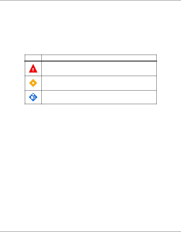
Table 1-1. Safety Symbol Definitions
Symbol |
Definition |
WARNING
Warnings alert users to potential serious outcomes (death, injury, or adverse events) to the patient, user, or environment.
Caution
Cautions alert users to exercise appropriate care for safe and effective use of the product.
Note
Notes provide additional guidelines or information.
1.3.2Warnings
WARNING:
Explosion hazard — Do not use in the presence of flammable anesthetics.
WARNING:
Shock hazard — Use only when connected to a grounded outlet to avoid electric shock.
WARNING:
Before attempting to open or disassemble, disconnect the power cord to avoid possible injury.
WARNING:
Use only Covidien-approved internal batteries.
WARNING:
The monitoring system is not defibrillator-proof. It may remain attached to the patient during defibrillation or during use of an electrosurgical unit,
1-2 |
Service Manual |

Safety Information
however, readings may be inaccurate during use in this environment and shortly thereafter.
WARNING:
Supplemental oxygen will attenuate patterns of desaturation. A patient’s respiratory compromise can be proportionally more severe before patterns appear in the saturation trend. Remain vigilant when monitoring a patient on supplemental oxygen.
WARNING:
Do not silence or disable audible alarms or decrease the volume of the audible alarm if patient safety could be compromised. Do not dim or disable visual alarms if patient safety could be compromised.
WARNING:
Ensure the monitoring system is clear of any obstructions that prevent awareness of visual or audible alarms. Failure to do so may result in inadvertently missing a visual alarm or an inaudible alarm tone.
WARNING:
Do not use any monitoring system, sensor, cable, or connector that appears damaged. Remove any damaged equipment from service for inspection by a qualified service technician.
WARNING:
Do not lift by the sensor or interface cable. The cable may disconnect, potentially dropping the monitoring system on a patient or damaging surface.
WARNING:
When installing the AC power cord, ensure the cord is carefully positioned to prevent tripping and entanglement.
WARNING:
Do not spray, pour, or spill any liquid on the monitoring system, its accessories, connectors, switches, or openings in the chassis, since this may cause damage to the monitoring system.
Service Manual |
1-3 |

Introduction
WARNING:
To ensure accurate performance and prevent device failure, do not subject to extreme moisture, such as direct exposure to rain. Such exposure may cause inaccurate performance or device failure.
WARNING:
The monitoring screen contains toxic chemicals. Do not touch a broken enclosure or monitoring screen. Physical contact with a broken enclosure or monitoring screen can result in transmission or ingestion of toxic substances.
WARNING:
No user serviceable parts inside.
1.3.3Cautions
Caution:
Federal law (U.S.A.) restricts this device to sale by or on the order of a physician.
Caution:
When connecting the monitoring system to any instrument, verify proper operation before clinical use. Both the monitoring system and the instrument connected to it must utilize a grounded outlet. Any equipment connected to the data interface must be certified according to the latest IEC/EN 60950 -1 standard for data-processing equipment, the latest IECEN 60601-1 standard for electromedical equipment, or the latest IEC/EN safety standards relevant to that equipment. All combinations of equipment must be in compliance with Requirements for Medical Electrical Systems IEC Standard 60601-1:2007and the electromagnetic compatibility IEC/EN Standard 60601-1:2005. Anyone who connects equipment to the data interface is configuring a medical system and, therefore, is responsible for ensuring that the system complies with the Requirements for Medical Electrical Systems IEC/EN Standard 60601-1-1:2007 and the electromagnetic compatibility IEC/ EN Standard 60601-1-2:2007. Accuracy may degrade if it is connected to secondary I/O devices when the equipment is not connected to earth reference.
1-4 |
Service Manual |

Obtaining Technical Assistance
Caution:
Observe electrostatic discharge (ESD) precautions prior to opening the chassis or handling any internal components.
Caution:
Observe the required torque for tightening screws. Over-tightening can strip out screw holes, rendering them useless.
1.4Obtaining Technical Assistance
1.4.1 Technical Services
For technical information and assistance, if unable to correct a problem while using the monitoring system, to order parts, or to order an Operator’s or Service Manual, contact Covidien or a local Covidien representative.
Covidien Technical Services: Patient Monitoring
15 Hampshire Street
Mansfield, MA 02048 USA
1.800.635.5267, 1.925.463.4635 (toll) or contact a local Covidien representative
www.covidien.com
When calling Covidien or a local Covidien representative, have the serial number, as well as the code versions available.
To locate the serial number and code versions
1. Press MENU.
2.Press ABOUT THE MONITOR.
3.Locate the serial number under Monitor Information and code versions under
Software Information.
Service Manual |
1-5 |

Introduction
1.4.2 On-Screen Help
The monitoring system provides users with an on-screen help system for various help topics. Reference To access on-screen help topics, p. 6-16.
1.5 Related Documents
Documentation is available online at www.covidien.com. Covidien makes available all appropriate information relevant to servicing monitoring system parts designated as repairable in this manual. For further assistance, contact Covidien.
•Nellcor™ Bedside Respiratory Patient Monitoring System Operator’s Manual — Provides basic information on operating the monitoring system and troubleshooting errors or malfunctions. Before using the monitoring system, thoroughly read this manual.
•Nellcor™ Sensor Instructions for Use — Guides sensor selection and usage. Before attaching any of the various Covidien-approved Nellcor™ sensors to the monitoring system, refer to their Instructions for Use.
•Nellcor™ Oxygen Saturation Accuracy Specification Grid — Provides sensor-specific guidance related to desired SpO2 saturation accuracy measurements.
1.6Warranty Information
To obtain information, contact Covidien or a local Covidien representative.
Purchase of this instrument confers no express or implied license under any Covidien patent to use that instrument with any sensor not manufactured or licensed by Covidien llc.
1-6 |
Service Manual |

2Product Specifications
2.1Overview
This chapter contains physical and operational specifications of the Nellcor™ Bedside Respiratory Patient Monitoring System. Ensure all product requirements are met prior to installation.
2.2 Physical Characteristics
Weight |
7.5 lbs. (3.4 kg) |
Dimensions |
10 in. x 6.5 in. x 5 in. (252 mm x 163 mm x 122 mm) |
2.3 Electrical Requirements
2.3.1 Power
Power Requirements |
Rated at 80-263 volts AC (nominal 120-230 VAC), 30 VA |
Input Frequency |
47/63 Hz |
Fuses |
Slow-blow 1.5 amp, 250 volts, IEC (5 x 20 mm) |
|
Quantity: 2 external |
2-1

Product Specifications
2.3.2Battery
Note:
The battery provides approximately seven hours of battery life when new and fully-charged with no alarms, no serial data, no analog output, no nurse call output, with backlight on while using a pulse simulator set for 200 bpm, high light and low modulation.
Type |
Lithium Ion |
Voltage |
7.2 Volts DC, 11.6 Ah, 83 Wh |
Recharge |
8 hours with monitoring system turned off |
|
12 hours with monitoring system turned on |
Shelf Life |
Four months, if monitoring system runs on new, fully-charged battery |
|
After four months storage, units run 33% of stated battery life |
Compliance |
IEC 62133 |
2.3.3 Rating of Nurse Call Relay
Maximum Input Voltage |
30 VAC or VDC (polarity is not important) |
Load Current |
120 mA continuous (peak 300 mA @ 100 ms) |
Minimum Resistance |
26.5 ohms to 50.5 ohms (40.5 ohms typical) during alarms |
Ground Reference |
Isolated Ground |
Electrical Isolation |
1500 Volts |
2-2 |
Service Manual |
Environmental Conditions
2.4 Environmental Conditions
2.4.1 Operating
Temperature |
5 ºC to 40 ºC (41 ºF to 104 ºF) |
Altitude |
-304.8 m to 4,572 m |
|
(-1,000 ft. to 15,000 ft.) |
Atmospheric Pressure |
105 kPa to 57.2 kPa |
|
(31.0 in. Hg to 16.89 in. Hg) |
Relative Humidity |
15% to 95% non-condensing |
2.4.2 Transport and Storage
|
Not in shipping container |
In shipping container |
|
Temperature |
-20 ºC to 60 ºC |
-20 ºC to 70 ºC |
|
|
(-4 ºF to 140 ºF) |
(-4 ºF to 158 |
ºF) |
Altitude |
-390 m to 5,574 m (-1,254 ft. to 18,288 ft.) |
|
|
Atmospheric Pressure |
50 kPa to 106 kPa (14.7 in. Hg to 31.3 in. Hg) |
|
|
Relative Humidity |
15% to 95% non-condensing |
|
|
Service Manual |
2-3 |

Product Specifications
2.5 Sensor Accuracy and Ranges
This monitoring system has the capability to detect physiological alarm conditions using SpO2 accuracy, pulse rate accuracy and alarm limit conditions.
Table 2-1. Nellcor™ Sensor Accuracy and Ranges |
||
|
|
|
|
Measurement Range |
|
|
|
|
SpO2 |
|
1% to 100% |
|
|
|
Pulse Rate |
|
20 to 250 beats per minute (bpm) |
|
|
|
Perfusion Range |
|
0.03% to 20% |
|
|
|
|
Accuracy1 |
|
Saturation |
|
|
|
|
|
Adult2, 3 |
|
70 to 100% ±2 digits |
Adult and Neonate Low Sat2, 3, 4 |
|
60 to 80% ±3 digits |
Neonate4, 5 |
|
70 to 100% ±2 digits |
Low Perfusion6 |
|
70 to 100% ±2 digits |
Adult and Neonate with Motion2, 7 |
|
70 to 100% ±3 digits |
Pulse Rate |
|
|
|
|
|
Adult and Neonate2, 3, 4 |
|
20 to 250 bpm ±3 digits |
Low Perfusion6 |
|
20 to 250 bpm ±3 digits |
Adult and Neonate with Motion2, 7 |
|
48 to 127 bpm ±5 digits |
1.Saturation accuracy varies by sensor type. Refer to the Nellcor™ Oxygen Saturation Accuracy Specification Grid at www.covidien.com/rms.
2.Accuracy specifications were validated using measurements of healthy non-smoking adult volunteers during controlled hypoxia studies spanning the specified saturation ranges. Subjects were recruited from the local population and comprised both men and women ranging in age from 18-50 years old, and spanned a range of skin pigmentations. Pulse oximeter SpO2 readings were compared to SaO2 values of drawn blood samples measured by hemoximetry. All accuracies are expressed as ±1 SD. Because pulse oximeter equipment measurements are statistically distributed, about two-thirds of the measurements can be expected to fall in this accuracy (ARMS) range (refer to the Sensor Accuracy Grid for more details).
3.Adult specifications are shown for OXIMAX MAX-A and MAX-N sensors with the Nellcor™ Bedside Respiratory Patient Monitoring System.
4.Neonate specifications are shown for OXIMAX MAX-N sensors with the Nellcor™ Bedside Respiratory Patient Monitoring System.
5.Clinical functionality of the MAX-N sensor has been demonstrated on a population of hospitalized neonate patients. The observed SpO2 accuracy was 2.5% in a study of 42 patients with ages of 1 to 23 days, weight from 750 to 4,100 grams, and 63 observations made spanning a range of 85% to 99% SaO2.
6.Specification applies to Nellcor™ Bedside Respiratory Patient Monitoring System oximeter performance. Reading accuracy in the presence of low perfusion (detected IR pulse modulation amplitude 0.03% - 1.5%) was validated using signals supplied by a patient simulator. SpO2 and pulse rate values were varied across the monitoring range over a range of weak signal conditions and compared to the known true saturation and pulse rate of the input signals.
7.Motion performance was validated during a controlled hypoxia blood study. Subjects performed rubbing and tapping movements 1-2 cm in amplitude with aperiodic intervals (randomly changing) with a random variation in frequency between 1-4 Hz. Applicability: OXIMAX MAX-A, MAX-AL, MAX-P, MAX-I, and MAX-N sensors.
2-4 |
Service Manual |

Sound Pressure
Table 2-2. Nellcor™ Sensor Operating Range and Power Dissipation
Operating Range and Dissipation
Red Light Wavelength |
Approximately 660 nm |
|
|
Infrared Light Wavelength |
Approximately 900 nm |
|
|
Optical Output Power |
Less than 15 mW |
|
|
Power Dissipation |
52.5 mW |
|
|
2.6 Sound Pressure
Table 2-3. Sound Pressure in Decibels
|
|
Volume Setting |
|
|
|
|
|
|
|
Alarm Type |
High |
Med High |
Med Low |
Low |
|
|
|
|
|
High Priority |
88.1 dB |
85.5 dB |
80.6 dB |
71.5 dB |
|
|
|
|
|
Medium Priority |
78.3 dB |
75.4 dB |
70.2 dB |
61.2 dB |
|
|
|
|
|
Low Priority |
74.4 dB |
71.1 dB |
66.4 dB |
57.6 dB |
|
|
|
|
|
SPD Alarm (Low Priority) |
74.4 dB |
70.7 dB |
65.7 dB |
57.5 dB |
|
|
|
|
|
2.7 Product Compliance
Equipment Classification |
IEC/EN 80601-2-61:2011 |
|
IEC/EN 60601-1:2005 |
|
CAN/CSA C22.2 No. 60601-1:08 |
|
ANSI AAMI ES 60601-1:2005 |
Protection Type |
Class I (Internally powered) |
Degree of Protection |
Type BF - Applied part |
Mode of Operation |
Continuous |
Electromagnetic Compatibility |
IEC 60601-1-2:2007 |
Liquid Ingress |
IPX1: Protected against harmful effects of dripping water |
Degree of Safety |
Not suitable for use in the presence of flammable anesthetics |
Service Manual |
2-5 |

Product Specifications
2.8 Manufacturer’s Declaration and Guidance
2.8.1Electromagnetic Compatibility (EMC)
WARNING:
This monitoring system is intended for use by healthcare professionals only. This monitoring system may cause radio interference or may disrupt the operation of nearby equipment, regardless of whether it is CISPR compliant or not. It may be necessary to take mitigation measures, such as re-orienting or relocating the monitoring system or shielding the location.
WARNING:
The use of accessories, sensors, and cables other than those specified may result in inaccurate readings of the monitoring system and increased EMI emissions of the monitoring system.
The monitoring system is suitable for prescription use only in the specified electromagnetic environments, in accordance with the IEC 60601-1-2:2007 standard. The monitoring system requires special precautions during installation and operation for electromagnetic compatibility. In particular, the use of nearby mobile or portable communications equipment may influence monitoring system performance.
Frequency and Bandwidth for Wireless Connection
Table 2-4. Frequency Band, Output Power, and Modulation Type
Frequency Band |
Output Power |
Modulation Type |
(MHz) |
(Watts) |
|
|
|
|
2412 - 2462 |
0.088 |
BPSK, CCK, OFDM |
|
|
|
5180 - 5240 |
0.018 |
OFDM |
|
|
|
5260 - 5320 |
0.018 |
OFDM |
|
|
|
5500 - 5700 |
0.028 |
OFDM |
|
|
|
5745 - 5825 |
0.026 |
OFDM |
|
|
|
2-6 |
Service Manual |

Manufacturer’s Declaration and Guidance
Electromagnetic Emissions
Table 2-5. Electromagnetic Emissions Guidelines and Compliance
Guidance and Manufacturer’s Declaration—Electromagnetic Emissions
(IEC/EN 60601-1-2:2007, Table 1)
The monitoring system is intended for use in the electromagnetic environment specified below. The customer or the user of the monitoring system should assure that it is used in such an environment.
Emissions Test |
Compliance |
Electromagnetic Environment Guidance |
|
|
|
RF emission |
Group 1, |
Not intended for use in a residential environment. If |
CISPR 11 |
Class A |
used in a domestic environment, may not offer ade- |
|
quate protection to radio-frequency communication |
|
EN 55011 |
|
|
|
services. The user may be required to take mitigation |
|
|
|
|
|
|
measures, such as relocating or re-orienting the equip- |
|
|
ment. |
|
|
|
Harmonic emissions |
Class A |
N/A |
IEC/EN 61000-3-2 |
|
|
|
|
|
Voltage fluctuation/ |
Complies |
N/A |
flicker emissions |
|
|
IEC/EN 61000-3-3 |
|
|
|
|
|
Service Manual |
2-7 |

Product Specifications
Electromagnetic Immunity
Table 2-6. Electromagnetic Immunity Guidelines and Compliance
Guidance and Manufacturer’s Declaration—Electromagnetic Immunity
(IEC/EN 60601-1-2:2007, Table 2)
The monitoring system is intended for use in the electromagnetic environment specified below. The customer or the user of the monitoring system should assure that it is used in such an environment.
Immunity |
IEC/EN 60601-1-2 |
Compliance |
Electromagnetic Environment |
||
|
Test |
Test Level |
Level |
Guidance |
|
|
|
|
|
||
Electrostatic |
± 6 kV contact |
± 6 kV contact |
Floor should be wood, concrete, |
||
discharge (ESD) |
± 8 kV air |
± 8 kV air |
or ceramic tile. If floors are |
||
|
|
covered with synthetic material, |
|||
IEC/EN 61000-4-2 |
|
|
|||
|
|
the relative humidity should be at |
|||
|
|
|
|
||
|
|
|
|
least 30%. |
|
|
|
|
|
||
Electric fast |
± 2 kV for power |
± 2 kV for |
Mains power quality should be |
||
transient/burst |
supply lines |
power supply lines |
that of a typical commercial and/ |
||
IEC/EN |
61000-4-4 |
± 1 kV input/ |
± 1 kV input/ |
or hospital environment. |
|
|
|||||
|
|
output lines |
output lines |
|
|
|
|
|
|
|
|
Surge |
|
± 1 kV differential |
± 1 kV differential |
Mains power quality should be |
|
IEC/EN |
61000-4-5 |
mode |
mode |
that of a typical commercial and/ |
|
|
|
or hospital environment. |
|||
|
|
± 2 kV common |
± 2 kV common |
||
|
|
|
|||
|
|
mode |
mode |
|
|
|
|
|
|
||
Voltage dips, short |
<5% UT |
<5% UT |
Mains power quality should be |
||
interruptions and |
(>95% dip in UT) |
(>95% dip in UT) |
that of a typical commercial and/ |
||
voltage variations |
for 0.5 cycle |
for 0.5 cycle |
or hospital environment. |
||
on power supply |
|
||||
|
|
If the user requires continued |
|||
40% UT |
40% UT |
||||
|
|
||||
IEC/EN 61000-4-11 |
operation during power mains |
||||
|
|
(60% dip in UT) |
(60% dip in UT) |
interruption, it is recommended |
|
|
|
for 5 cycles |
for 5 cycles |
that the monitoring system be |
|
|
|
powered from an uninterruptible |
|||
|
|
|
|
||
|
|
|
|
||
|
|
70% UT |
70% UT |
power supply or battery. |
|
|
|
(30% dip in UT) |
(30% dip in UT) |
|
|
|
|
for 25 cycles |
for 25 cycles |
|
|
|
|
|
|
|
|
|
|
<5% UT |
<5% UT |
|
|
|
|
(>95% dip in UT) |
(>95% dip in UT) |
|
|
|
|
for 5 seconds |
for 5 seconds |
|
|
|
|
|
|
||
Power frequency |
3 A/m |
3 A/m |
It may be necessary to position |
||
(50/60 Hz) magnetic |
|
|
further from the sources of |
||
field |
|
|
|
power frequency magnetic fields |
|
IEC/EN |
61000-4-8 |
|
|
or to install magnetic shielding. |
|
|
|
|
|||
|
|
|
|
|
|
Note: UT is the AC main’s voltage prior to application of the test level.
2-8 |
Service Manual |
Manufacturer’s Declaration and Guidance
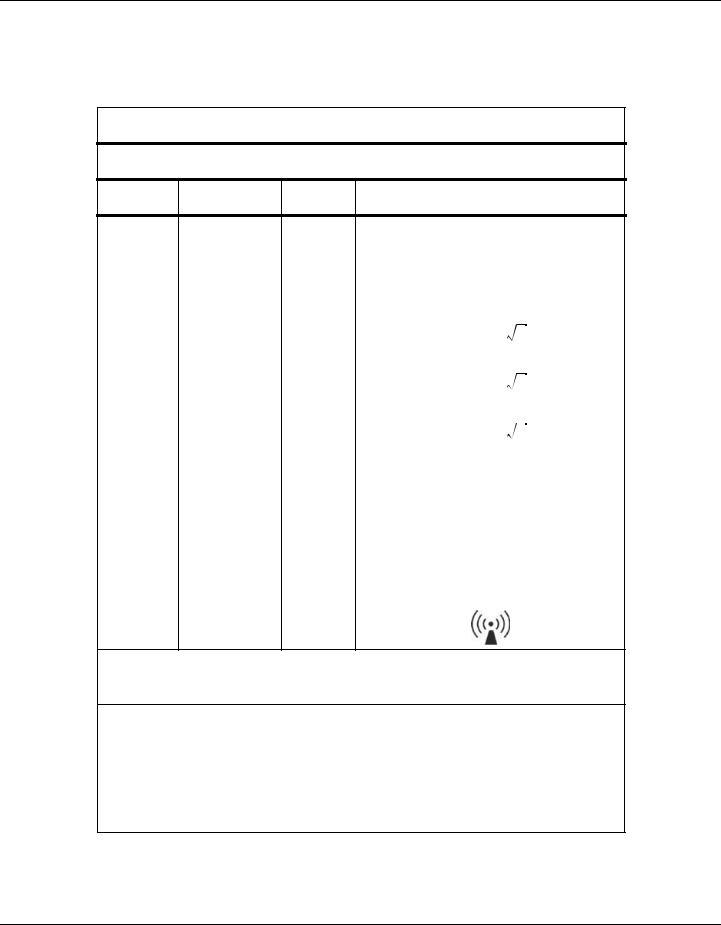
Table 2-7. Recommended Separation Distance Calculations
Guidance and Manufacturer’s Declaration—Electromagnetic Immunity
(IEC/EN 60601-1-2:2007, Table 4)
The monitoring system is intended for use in the electromagnetic environment specified below. The customer or the user of the monitoring system should assure that it is used in such an environment.
Immunity |
IEC/EN 60601-1-2 |
Compliance |
Electromagnetic |
Test |
Test Level |
Level |
Environment Guidance |
Portable and mobile RF communications equipment should be used no closer to any part of the monitoring system, including cables, than the recommended separation distance calculated from the equation applicable to the frequency of the transmitter.
Conducted RF |
3 Vrms |
3 Vrms |
Recommended Separation Distance |
|||
d = |
1.2 |
P |
||||
IEC/EN |
150 kHz to |
150 kHz to |
||||
61000-4-6 |
80 MHz |
80 MHz |
|
|
|
|
Radiated RF |
3 V/m |
3 V/m |
d = |
1.2 |
P |
|
IEC/EN |
80 MHz to |
80 MHz to |
80 MHz to 800 MHz |
|||
61000-4-3 |
2.5 GHz |
2.5 GHz |
||||
|
|
|
||||
|
|
|
d = |
2.3 |
P |
|
800 MHz to 2.5 GHz
where P is the maximum output power rating of the transmitter in watts (W) according to the transmitter manufacturer and d is the recommended separation distance in meters (m).
Field strengths from fixed RF transmitters, as determined by an electromagnetic site surveya, should be less than the compliance level in each frequency rangeb.
Interference may occur in the vicinity of equipment marked with the following symbol:
NOTE 1: At 80 MHz and 800 MHz, the higher frequency range applies.
NOTE 2: These guidelines may not apply in all situations. Electromagnetic propagation is affected by absorption and reflection from structures, objects, and people.
aField strengths from fixed transmitters, such as base stations for radio (cellular/cordless) telephones and land mobile radios, amateur radio, AM and FM radio broadcast and TV broadcast cannot be predicted theoretically with accuracy. To assess the electromagnetic environment due to fixed RF transmitters, an electromagnetic site survey should be considered. If the measured field strength in the location in which the monitoring system is used exceeds the applicable RF compliance level above, the monitoring system should be observed to verify normal operation. If abnormal performance is observed, additional measures may be necessary, such as re-orienting or relocating the monitoring system.
bOver the frequency range 150 kHz to 80 MHz, field strengths should be less than 3 V/m.
Service Manual |
2-9 |

Product Specifications
Table 2-8. Recommended Separation Distances
Recommended Separation Distances Between Portable and Mobile RF Communications
Equipment and the Monitoring System
(IEC/EN 60601-1-2:2007, Table 6)
The monitoring system is intended for use in an electromagnetic environment in which radiated RF disturbances are controlled. The customer or the user of the monitoring system can help prevent electromagnetic interference by maintaining a minimum distance between portable and mobile RF communications equipment (transmitters) and the monitoring system as recommended below, according to the maximum output power of the communications equipment.
Rated Maximum |
Separation Distance According to Frequency of Transmitter in Meters |
|||
Output Power (P) |
|
|
|
|
d = 1.2 P |
d = 1.2 P |
d = 2.3 P |
||
of Transmitter in |
||||
|
|
|
||
Watts |
150 kHz to 80 MHz |
80 MHz to 800 MHz |
800 MHz to 2.5 GHz |
|
|
||||
|
|
|
|
|
0.01 |
0.12 |
0.12 |
0.23 |
|
|
|
|
|
|
0.10 |
0.38 |
0.38 |
0.73 |
|
|
|
|
|
|
1.00 |
1.20 |
1.20 |
2.30 |
|
|
|
|
|
|
10.00 |
3.80 |
3.80 |
7.30 |
|
|
|
|
|
|
100.00 |
12.00 |
12.00 |
23.00 |
|
|
|
|
|
|
For transmitters rated at a maximum output power not listed above, the recommended separation distance (d) in meters (m) can be estimated using the equation applicable to the frequency of the transmitter, where P is the maximum output power rating of the transmitter in watts (W) according to the transmitter manufacturer.
NOTE 1: At 80 MHz and 800 MHz, the separation distance for the higher frequency range applies.
NOTE 2: These guidelines may not apply in all situations. Electromagnetic propagation is affected by absorption and reflection from structures, objects, and people.
2-10 |
Service Manual |

Manufacturer’s Declaration and Guidance
Sensor and Cable Compliance
WARNING:
The use of accessories, sensors, and cables other than those specified may result in inaccurate readings of the monitoring system and increased emission of the monitoring system.
Table 2-9. Sensor and Cable Length
Item |
SKU |
Maximum Length |
|
|
|
|
|
Sensors |
|
|
|
|
|
|
|
Nellcor™ Adult SpO2 Sensor, Reusable (Nonsterile) |
DS100A |
3.0 ft. (0.9 m) |
|
|
|
|
|
Nellcor™ Adult XL SpO2 Sensor (Sterile, single-use only) |
MAX-AL |
3.0 ft. (0.9 m) |
|
|
|
|
|
Nellcor™ Forehead SpO2 Sensor (Sterile, single-use only) |
MAX-FAST |
2.5 ft (0.75 m) |
|
|
|
|
|
Nellcor™ Neonatal-Adult SpO2 Sensor |
MAX-N |
|
|
(Sterile, single-use only) |
|
|
|
|
|
|
|
Nellcor™ Infant SpO2 Sensor (Sterile, single-use only) |
MAX-I |
|
|
|
|
1.5 ft. (0.5 m) |
|
Nellcor™ Pediatric SpO2 Sensor (Sterile, single-use only) |
MAX-P |
||
|
|||
|
|
|
|
Nellcor™ Adult SpO2 Sensor (Sterile, single-use only) |
MAX-A |
|
|
|
|
|
|
Nellcor™ Adult SpO2 Nasal Sensor (Sterile, single-use only) |
MAX-R |
|
|
|
|
|
|
Nellcor™ Adult-Neonatal SpO2 Sensor with Wraps |
OXI-A/N |
|
|
(Reusable with adhesive) |
|
3.0 ft. (0.9 m) |
|
|
|
||
Nellcor™ Pediatric-Infant SpO2 Sensor with Wraps |
OXI-P/I |
||
|
|||
(Reusable with adhesive) |
|
|
|
|
|
|
|
Nellcor™ Pediatric SpO2 Sensor, Two Piece |
P |
|
|
(Sterile, single-use only) |
|
|
|
|
|
|
|
Nellcor™ Neonatal-Adult SpO2 Sensor, Two Piece |
N |
OC-3 cable, |
|
(Sterile, single-use only) |
|
3.0 ft. (0.9 m) |
|
|
|
|
|
Nellcor™ Adult SpO2 Sensor, Two Piece |
A |
|
|
(Sterile, single-use only) |
|
|
|
|
|
|
|
Nellcor™ SpO2 Sensor, Multisite Reusable (Nonsterile) |
D-YS |
|
|
|
|
4.0 ft. (1.2 m) |
|
• Nellcor™ SpO2 Ear Clip, Reusable (Nonsterile) |
D-YSE |
||
|
|
|
|
• Nellcor™ Pediatric SpO2 Clip, Reusable (Nonsterile) |
D-YSPD |
|
|
|
|
|
Service Manual |
2-11 |

Product Specifications
Table 2-9. Sensor and Cable Length (Continued)
Item |
SKU |
Maximum Length |
|
|
|
Cables |
|
|
|
|
|
Power cord |
---- |
9.84 ft. (3 m) |
|
|
|
DOC-10 interface cable |
|
10.0 ft. (3 m) |
|
|
|
Firmware download cable, RS-232 serial, 15 to 9 pin “D” |
|
10.0 ft. (3 m) |
|
|
|
Non-terminated cable, RS-232 analog, 15 pin “D” |
|
3.3 ft. (1 m) |
|
|
|
Printer cable, RS-232, 15 to 9 pin “D” |
|
10.0 ft. (3 m) |
|
|
|
Philips interface cable |
M1943 NL |
3.3 ft. (1 m) |
|
|
|
Oxinet™ III hardwire cable |
---- |
10.0 ft. (3 m) |
|
|
|
Oxinet™ III data cable |
|
|
|
|
|
2.8.2 Ground Integrity |
|
|
100 milliohms or less
2.8.3 Safety Tests
The following tables describe the maximum earth and enclosure leakage current allowed, as well as patient leakage.
Table 2-10. Earth and Enclosure Leakage Current Specifications
Earth Leakage Current
|
|
|
Neutral |
|
ANSI/AAMI |
|
Condition |
AC Line Polarity |
Line Cord |
Line Cord |
IEC 60601-1 |
60601-1 |
|
|
|
|
|
|
|
|
Normal |
Normal |
Closed |
Closed |
500 μA |
300 |
μA |
|
|
|
|
|
|
|
Single Fault |
|
Open |
Closed |
|
1000 |
μA |
|
|
|
|
|
|
|
|
|
Closed |
Open |
|
|
|
|
|
|
|
|
|
|
Normal |
Reversed |
Closed |
Closed |
500 μA |
300 |
μA |
|
|
|
|
|
|
|
Single Fault |
|
Open |
Closed |
|
1000 |
μA |
|
|
|
|
|
|
|
|
|
Closed |
Open |
|
|
|
|
|
|
|
|
|
|
2-12 |
Service Manual |
Loading...