


ForceTriad Energy Platform
Customert Supportupport
Calibrationl ti Proceduredure
Troubleshootingr l shooting
Systemt Serviceervice
Periodici ic Safetyafety CheckCheck

Main Menu
Covidien Customer Support Contacts
Click anywhere on the map to access the Covidien technical support website
Covidien | December 7, 2011 | Confidential
Main Menu
Calibration Procedure
CALIBRATION PROCEDURE DEFINITION
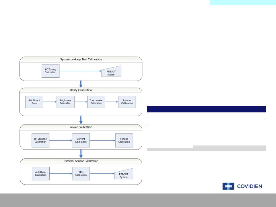
The calibration procedure has been broken down into four different areas of calibration. The different calibration areas segregate the full calibration procedure into smaller, more manageable calibration sections. These sections are then selected based on the service performed. Additional information can be found by clicking on the flow chart below.
The different calibration levels defined below are the
MINIMUM requirement of level of calibration to be performed. Ultimately, a full, level 6 calibration is preferred for all levels of service work completed.
The full calibration procedure definition, including a step- by-step procedure, can be found in the ForceTriad Service Manual. The information found in the Calibration Procedure section of this guide is for reference only.
Calibration Level Definition
Calibration Level 0 |
No calibration required |
|
Periodic Safety Check required |
|
|
|
Calibration Level 1 |
Scanner Calibration |
|
|
|
|
|
|
Calibration Level 2 |
System Leakage Null Calibration |
|
|
|
|
|
|
Calibration Level 3 |
System Leakage Null Calibration |
|
|
Utility Calibration |
|
|
|
|
|
|
|
|
|
|
|
Calibration Level 4 |
Power Calibration |
|
|
System Leakage Null Calibration |
|
|
|
|
|
|
|
|
|
|
|
Calibration Level 5 |
Power Calibration |
|
|
External Sensor Calibration |
|
|
|
|
System Leakage Null Calibration |
|
|
|
|
|
|
Calibration Level 6 |
Full calibration required |
|
|
|
|
|
Covidien | December 7, 2011 | Confidential
CalibrationMain MenuProcedure
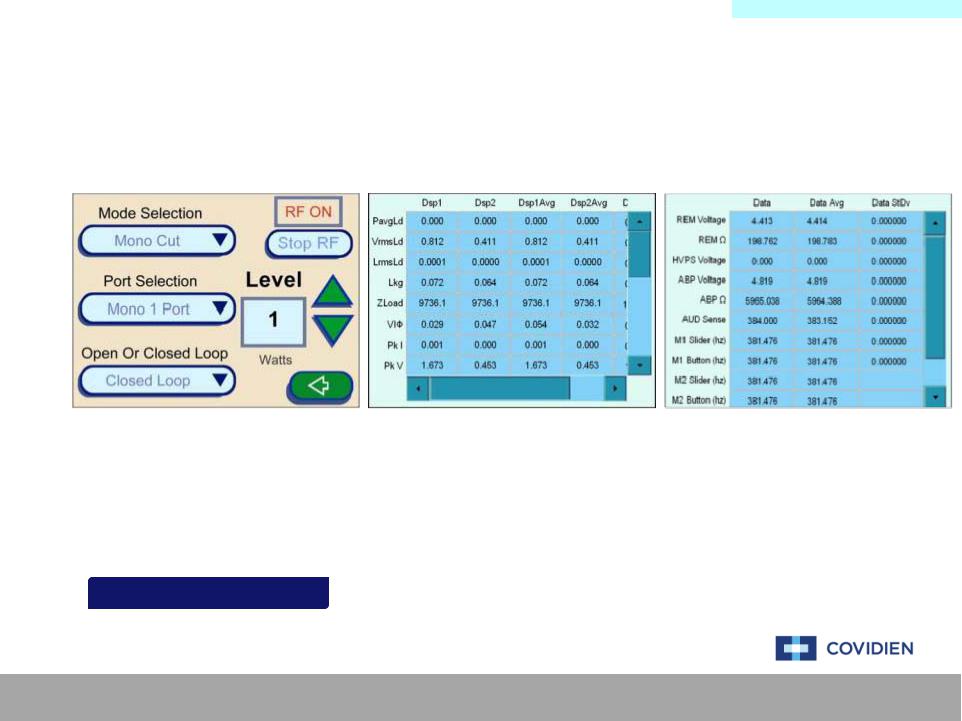
System Leakage Null Calibration
The System Leakage Null Calibration process consists of adjusting the LC Tuning on the system. This is
accomplished by using the equipment outlined below and using the touch screen menu navigating to the calibration section.
Main Menu Service Diagnostics Debug Mode
|
|
Item |
Qty |
|
|
Ground Lug Cable |
1 |
|
|
|
|
|
|
D4 Cable with Current Probe |
1 |
|
|
||
|
|
|
|
|
|
Current Monitor |
1 |
|
|
|
|
|
|
REM Adaptor |
1 |
LCLC Tuning Setupetup ExampleExample |
|
||
|
|
|
|
#0 Flathead Screwdriver |
1 |
||
|
|
|
|
Covidien | December 7, 2011 | Confidential

SystemMainLeakgeMenuNull Cal
LC Tuning Calibration Setup
Covidien | December 7, 2011 | Confidential

CalibrationMain MenuProcedure
Utility Calibration
The Utility Calibration process consists of setting up the date & time, screen brightness, touch screen, and
scanners on the system. This is accomplished by using the equipment outlined below and using the touch screen menu navigating to the calibration section.
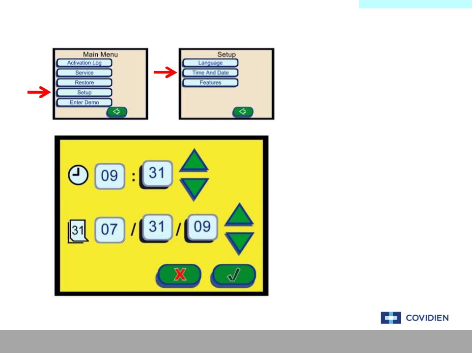
TIME & DATE:
Main Menu Setup Time And Date
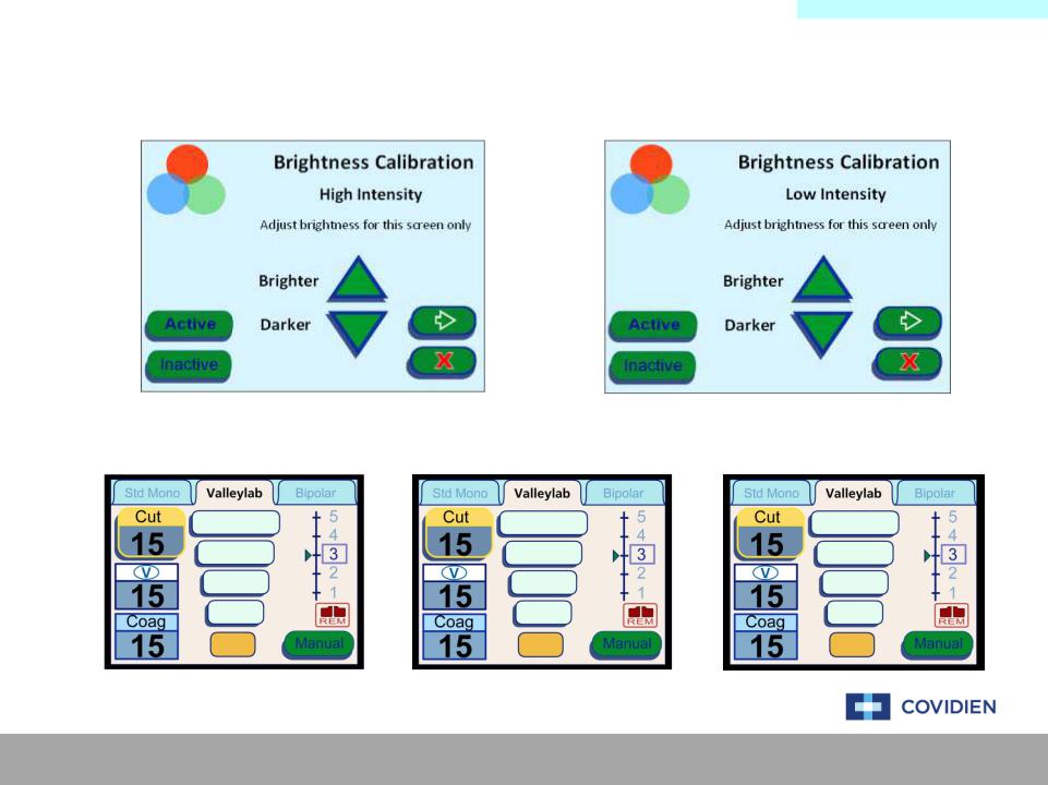
BRIGHTNESS, TOUCH SCREEN, & SCANNER:
Main Menu Service Maintenance Calibrate Brightness
Touch Screen
Scanner
SetSetTimeTi e & Datete Examplexample
Brightness |
t |
xample |
|
|
|
|
Brightness |
Setup Example |
|
|
|
||
|
|
|
|
|
|
|
TouchscreenScreenSetupt Examplexa ple |
|
Item |
Qty |
|||
|
|
|
|
|
Stylus (Optional) |
1 |
|
|
|
|
|
||
ScannerSc |
Setupt |
ExampleExample |
|
|||
|
|
|
||||
Ligasure 1 Dot Code Instrument |
1 |
|||||
|
|
|
|
|
|
|
Covidien | December 7, 2011 | Confidential
UtilityMainCalibrationMenu
Set Time & Date Setup
DATE & TIME SETUP PROCEDURE
Navigate the ForceTriad touch screen menu to “Setup”, then “Time And Date” to the screen to the left. On this screen, use the green up and down arrows to set the date and time.
After completion of setting the date and time, select the green check mark to store the date &
time.
Covidien | December 7, 2011 | Confidential
UtilityMainCalibrationMenu
Brightness Calibration Setup
High Intensity |
|
Low Intensity |
|
|
|
|
|
|
|
|
|
|
|
|
|
High Intensity |
Low Intensity |
Inactive Screen |
Covidien | December 7, 2011 | Confidential
UtilityMainCalibrationMenu
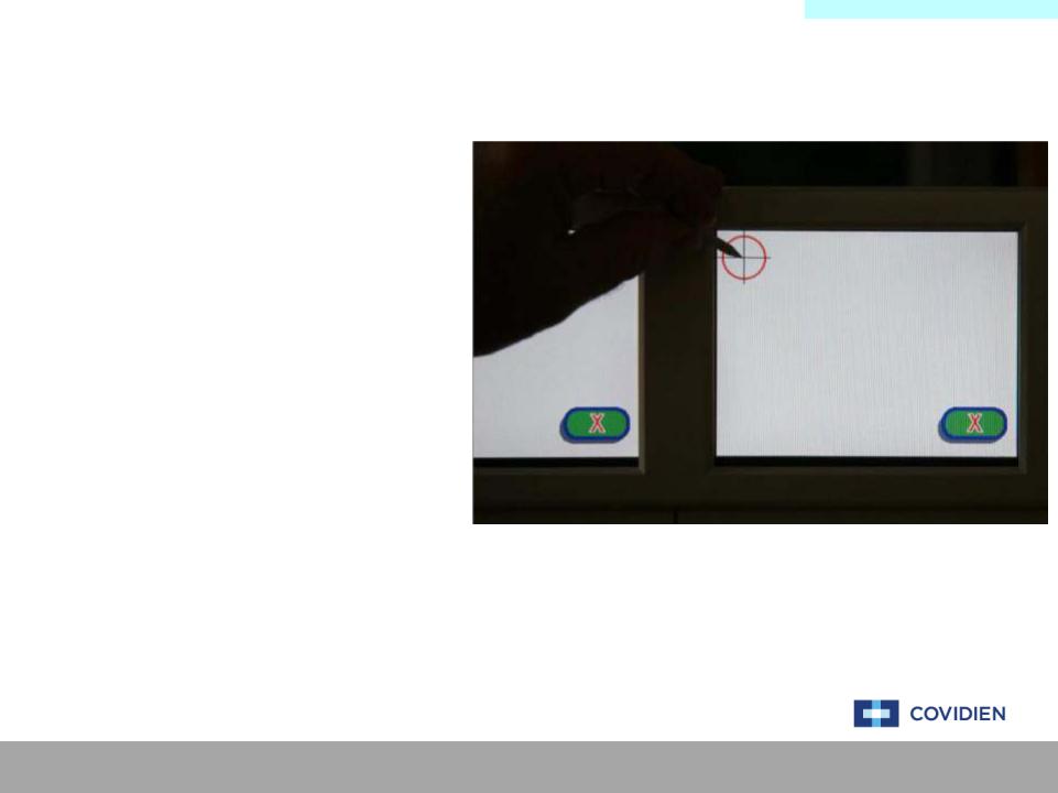
Touch Screen Calibration Setup
TOUCH SCREEN SETUP PROCEDURE
Under the “Calibration” section of the touch screen menu, select the touch screen calibration. You will be prompted to touch the crosshair icon on the screen.
Preferably using a stylus, begin touching the center mark of the crosshairs beginning with the left screen moving right.
Your finger tip is an acceptable alternative to the stylus.
Covidien | December 7, 2011 | Confidential

UtilityMainCalibrationMenu
Scanner Calibration Setup
Scanner Calibration
Performing initial scanner calibration on all ports.
Please wait for calibration to complete.
Cancel may leave scanners in unusable state.
SCANNER SETUP PROCEDURE
Under the “Calibration” section of the touch screen menu, select the scanner calibration. You will be prompted to
.
Using appropriate hand pieces, insert the hand piece into the corresponding receptacles as prompted by the on screen commands.
Covidien | December 7, 2011 | Confidential
CalibrationMain MenuProcedure
Power Calibration
The Power Calibration process consists of measuring the RF leakage, current, and voltage on the system. This is
accomplished by using the equipment outlined below and using the touch screen menu navigating to the calibration section.
Main Menu Service Maintenance Calibrate Leakage
Current Cal
Voltage Cal
|
|
|
|
|
|
Item |
Qty |
|
|
|
|
|
|
|
Ground Lug Cable |
1 |
|
|
RFRFLeakageLe |
Setupetup ExampleExample |
|
|
|
|||
|
|
D4 Cable with Current Probe |
1 |
|||||
|
|
|
|
|
|
Current Monitor |
1 |
|
|
|
|
|
|
|
|||
|
Current C l |
t |
xample |
|
||||
|
|
|
|
|||||
|
|
|||||||
|
Current |
Cal Setup Example |
|
REM Adaptor |
1 |
|||
|
|
|
|
|
|
|
|
|
|
Voltage |
|
etup Example |
|
Cable Lead |
2 |
||
|
Voltage |
Cal Setup |
Example |
|
|
|
||
|
|
|
|
|
|
Resistors (1KΩ & 5KΩ - 250W) |
1 |
|
|
|
|
|
|
|
|||
|
|
|
|
|
|
|
|
|
WARNING: Do not hold down on the pushbuttons!
Covidien | December 7, 2011 | Confidential

PowerMainCalibrationMenu
RF Leakage Calibration Setup
WARNING: Do not hold down on the pushbuttons!
Covidien | December 7, 2011 | Confidential
PowerMainCalibrationMenu
Current Calibration Setup
WARNING: Do not hold down on the pushbuttons!
Covidien | December 7, 2011 | Confidential
PowerMainCalibrationMenu
Voltage Calibration Setup
WARNING: Do not hold down on the pushbuttons!
Covidien | December 7, 2011 | Confidential
CalibrationMain MenuProcedure
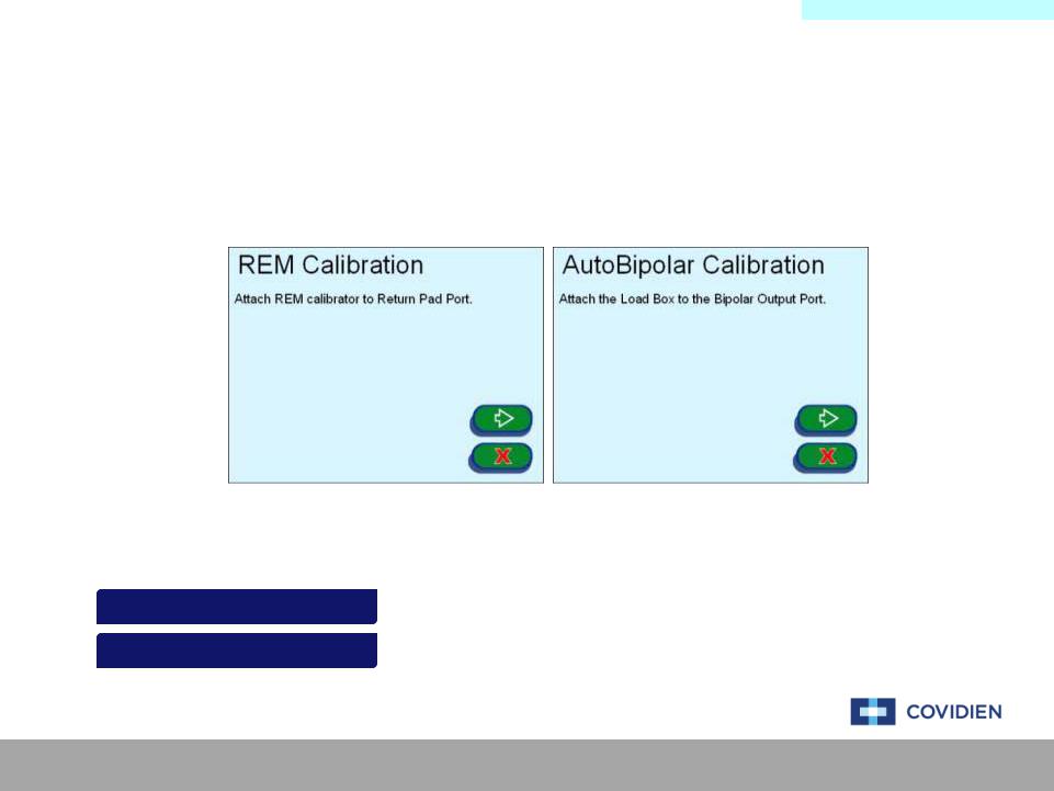
External Sensor Calibration
The External Sensor Calibration process consists of measuring the REM and AutoBipolar settings on the system.
This is accomplished by using the equipment outlined below and using the touch screen menu navigating to the calibration section.
Main Menu Service Maintenance Calibrate REM
AutoBip
|
|
Item |
Qty |
|
|
|
REM Calibrator |
1 |
|
AutobipolarAutoBipolarSetuptup Examplele |
|
Load Box |
1 |
|
|
|
REM Calibration Cable |
1 |
|
|
|
|||
REMREM Setupt Examplexample |
|
|||
|
|
|
||
AutoBipolar Cable |
1 |
|||
|
|
|||
|
|
|
|
Covidien | December 7, 2011 | Confidential

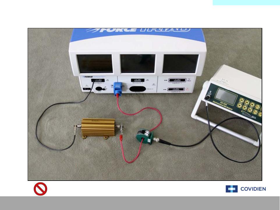
ExternalMainSensorMenuCalibration
Autobipolar Calibration Setup
Covidien | December 7, 2011 | Confidential

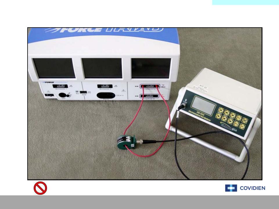
ExternalMainSensorMenuCalibration
REM Calibration Setup
Covidien | December 7, 2011 | Confidential
Main Menu
Error Code Definition & Troubleshooting
E2 |
E11 |
E20 |
E258 |
E267 |
E276 |
E285 |
E294 |
E303 |
|
E20 |
E258 |
E267 |
E294 |
E303 |
|||||
E2 |
E11 |
E276 |
E285 |
||||||
E3 |
E12 |
E21 |
E259 |
E268 |
E277 |
E286 |
E295 |
E304 |
|
E21 |
E259 |
E295 |
E304 |
||||||
E3 |
E12 |
E268 |
E277 |
E286 |
E4 |
E13 |
E22 |
E260 |
E269 |
E278 |
E287 |
E296 |
E305 |
|
E22 |
E260 |
E305 |
|||||||
E4 |
E13 |
E269 |
E278 |
E287 |
E296 |
||||
E5 |
E14 |
E23 |
E261 |
E270 |
E279 |
E288 |
E297 |
E306 |
|
E23 |
E261 |
E297 |
E306 |
||||||
E5 |
E14 |
E270 |
E279 |
E288 |
E6 |
E15 |
E24 |
E262 |
E271 |
E280 |
E289 |
E298 |
E307 |
|
E24 |
E262 |
E298 |
E307 |
||||||
E6 |
E15 |
E271 |
E280 |
E289 |
|||||
|
E16 |
E25 |
E263 |
E272 |
E281 |
E290 |
E299 |
E308 |
|
E7E7 |
E308 |
||||||||
E16 |
E25 |
E263 |
E272 |
E281 |
E290 |
E299 |
E8 |
E17 |
E26 |
E264 |
E273 |
E282 |
E291 |
E300 |
E309 |
|
E26 |
E264 |
E300 |
E309 |
||||||
E8 |
E17 |
E273 |
E282 |
E291 |
|||||
E9 |
E18 |
E27 |
E265 |
E274 |
E283 |
E292 |
|
E310 |
|
E27 |
E265 |
E301E301 |
E310 |
||||||
E9 |
E18 |
E274 |
E283 |
E292 |
|
E19 |
E257 |
E266 |
E275 |
E284 |
E293 |
E302 |
E311 |
|
E10E10 |
E275 |
E284 |
E293 |
E311 |
|||||
E19 |
E257 |
E266 |
E302 |
NonNon--ErrorErrorCode FailuresFailures
Covidien | December 7, 2011 | Confidential

Main Menu
Non-Error Code Troubleshooting
GrayGray ScreensScreens
BlackBlack ScreensScreens
DarkDark ScreensScreens
FlickeringFlickering ScreensScreens
NoNo PowerPower
UserUserSelfSelf--TestTestErrorError
The system responds to a power cycle and begins the system initiation. The three display screens show a blank, gray screen instead of displaying the white Covidien screen.
.
display screens show a blank, black screen instead of displaying the white Covidien screen.
The system responds to a power cycle and begins the system initiation. The three display screens show a much darker screen of the expected white Covidien screen.
This can range from slightly darker to nearly unreadable.
The system responds to a power cycle and begins the system initiation. The screen and/or screens begin to flicker. The flickering can happen once or occur constantly.
The system does not respond to a power cycle. The system displays and scanners do not illuminate.
The system initiates the self-test and may pass a portion of the testing. The unit then fails at some point during the self-test. The unit will generate an error but not an error code.
ErrorErrorCode Failuresailures
Covidien | December 7, 2011 | Confidential

Non-ErrorMainCodeMenuMenu
Non-Error Code Failures - Gray Screens
The failures that are generated where the displays are blank and gray, there are a couple of scenarios that could cause this. Typically, cables that are not connected or fully connected are the cause.
NON-COMPONENT ACTIONS
1.Power cycling the system
2.Inspecting the component cables
LEADING COMPONENT REPLACEMENTS
1.Ethernet Cable
•(Cable between Controller and Display)
2.Steering Relay Cable
•(Cable between SR and Display)
NON-COMPONENT ACTIONS INSTRUCTION
1. Power Cycle the unit and allow the system to perform the self-test.
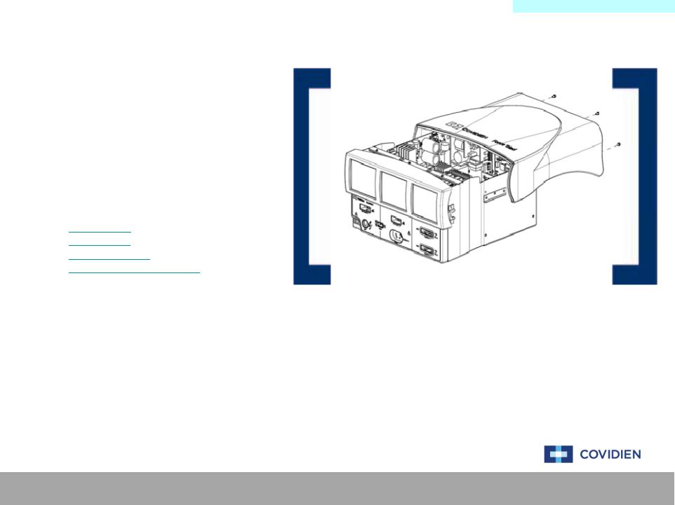
2.Remove the cover to the ForceTriad system and inspect the system boards ensuring that the boards are properly seated within the unit and that all cables are also securely connected.
Covidien | December 7, 2011 | Confidential
Non-ErrorMainCodeMenuMenu
Non-Error Code Failures - Black Screens
The failures that are generated where the displays are blank and black, there is typically one cause of this type of failure, the inverter board.
NON-COMPONENT ACTIONS
1.Power cycling the system
2.Inspecting the component cables
LEADING COMPONENT REPLACEMENTS
1. Inverter Board
NON-COMPONENT ACTIONS INSTRUCTION
1. Power Cycle the unit and allow the system to perform the self-test.
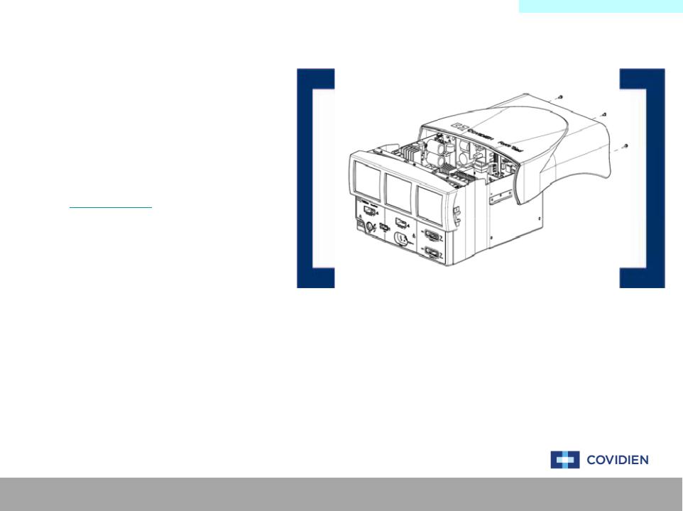
2.Remove the cover to the ForceTriad system and inspect the system boards ensuring that the boards are properly seated within the unit and that all cables are also securely connected.
Covidien | December 7, 2011 | Confidential
Non-ErrorMain CodeMenuMenu
Non-Error Code Failures – No Power
The failures that are generated where the system does not power on nor is there any indication that the system received a signal to power on. There are a couple of possibilities to cause this type of failure.
NON-COMPONENT ACTIONS
1.Power cycling the system
2.Inspecting the component cables
LEADING COMPONENT REPLACEMENTS
1.System Fuse
2.Power Cable
3.Controller Board
4.Low Voltage Power Supply
NON-COMPONENT ACTIONS INSTRUCTION
1. Power Cycle the unit and allow the system to perform the self-test.
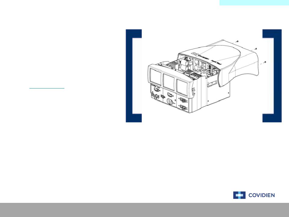
2.Remove the cover to the ForceTriad system and inspect the system boards ensuring that the boards are properly seated within the unit and that all cables are also securely connected.
Covidien | December 7, 2011 | Confidential

Non-ErrorMain CodeMenuMenu
Non-Error Code Failures – User Self-Test
The failure that is generated where the system fails a user generated self-test via the “Diagnostics” menu the typical failure mode is the Footswitch Board.
NON-COMPONENT ACTIONS
1.Power cycling the system
2.Inspecting the component cables
LEADING COMPONENT REPLACEMENTS
1. Footswitch Board
NON-COMPONENT ACTIONS INSTRUCTION
1. Power Cycle the unit and allow the system to perform the self-test.
2.Remove the cover to the ForceTriad system and inspect the system boards ensuring that the boards are properly seated within the unit and that all cables are also securely connected.
Covidien | December 7, 2011 | Confidential

Non-ErrorMainCodeMenuMenu
Non-Error Code Failures – Flickering Screens
The failure that is generated where the system fails a user generated self-test via the “Diagnostics” menu the typical failure mode is the Footswitch Board.
NON-COMPONENT ACTIONS
1.Power cycling the system
2.Inspecting the component cables
LEADING COMPONENT REPLACEMENTS
1.Power Cable
• (Cable between SR and Display)
NON-COMPONENT ACTIONS INSTRUCTION
1. Power Cycle the unit and allow the system to perform the self-test.
2.Remove the cover to the ForceTriad system and inspect the system boards ensuring that the boards are properly seated within the unit and that all cables are also securely connected.
Covidien | December 7, 2011 | Confidential

Non-ErrorMain CodeMenuMenu
Non-Error Code Failures – Dark Screens
The failure that is generated where the system fails a user generated self-test via the “Diagnostics” menu the typical failure mode is the Footswitch Board.
NON-COMPONENT ACTIONS
1.Power cycling the system
2.Inspecting the component cables
3.Brightness calibration
LEADING COMPONENT REPLACEMENTS
1. Display Inverter
NON-COMPONENT ACTIONS INSTRUCTION
1. Power Cycle the unit and allow the system to perform the self-test.
2.Remove the cover to the ForceTriad system and inspect the system boards ensuring that the boards are properly seated within the unit and that all cables are also securely connected.
3.Perform a brightness calibration as outlined in the Service Manual.
Covidien | December 7, 2011 | Confidential
Error CodeMainDefinitionMenu Menu
E2 – ERR_SE_ICL_ERROR
The E2 error code is designated and issued to signify that the unit is unable to communicate to the hardware using the HOST ICL registers.
NON-COMPONENT ACTIONS
1. Power cycling the system
2. Performing a full recalibration
LEADING COMPONENT REPLACEMENTS
1. Controller Board
NON-COMPONENT ACTIONS INSTRUCTION
1. Power Cycle the unit and allow the system to perform the self-test.
2.Remove the cover to the ForceTriad system and inspect the system boards ensuring that the boards are properly seated within the unit and that all cables are also securely connected.
3.Perform a level 6 calibration as outlined in the Calibration Section.
Covidien | December 7, 2011 | Confidential
Error CodeMainDefinitionMenu Menu
E3 – ERR_SE_APP_ROM_FAIL
The E3 error code is designated and issued to signify that the DSP application ROM check failed during start-up.
NON-COMPONENT ACTIONS
1. Power cycling the system
2. Performing a full recalibration
LEADING COMPONENT REPLACEMENTS
1. Controller Board
NON-COMPONENT ACTIONS INSTRUCTION
1. Power Cycle the unit and allow the system to perform the self-test.
2.Remove the cover to the ForceTriad system and inspect the system boards ensuring that the boards are properly seated within the unit and that all cables are also securely connected.
3.Perform a level 6 calibration as outlined in the Calibration Section.
Covidien | December 7, 2011 | Confidential

Error CodeMainDefinitionMenu Menu
E4 – ERR_SE_BOOT_ROM_FAIL
The E4 error code is designated and issued to signify that the DSP boot ROM check failed during start-up.
NON-COMPONENT ACTIONS
1. Power cycling the system
2. Performing a full recalibration
LEADING COMPONENT REPLACEMENTS
1. Controller Board
NON-COMPONENT ACTIONS INSTRUCTION
1. Power Cycle the unit and allow the system to perform the self-test.
2.Remove the cover to the ForceTriad system and inspect the system boards ensuring that the boards are properly seated within the unit and that all cables are also securely connected.
3.Perform a level 6 calibration as outlined in the Calibration Section.
Covidien | December 7, 2011 | Confidential

Error CodeMainDefinitionMenu Menu
E5 - ERR_SE_RAM_FAIL
The E5 error code is designated and issued to signify that the DSP RAM check failed during start-up.
NON-COMPONENT ACTIONS
1. Power cycling the system
2. Performing a full recalibration
LEADING COMPONENT REPLACEMENTS
1. Controller Board
NON-COMPONENT ACTIONS INSTRUCTION
1. Power Cycle the unit and allow the system to perform the self-test.
2.Remove the cover to the ForceTriad system and inspect the system boards ensuring that the boards are properly seated within the unit and that all cables are also securely connected.
3.Perform a level 6 calibration as outlined in the Calibration Section.
Covidien | December 7, 2011 | Confidential

Error CodeMainDefinitionMenu Menu
E6 – ERR_SE_RTOS_FAIL
The E6 error code is designated and issued to signify that a software error has occurred. The E6 error code is typically issued during real time to signify an operating system error.
NON-COMPONENT ACTIONS
1.Power cycling the system
2.Performing a full recalibration
LEADING COMPONENT REPLACEMENTS
1.Controller Board
2.System Display
NON-COMPONENT ACTIONS INSTRUCTION
1. Power Cycle the unit and allow the system to perform the self-test.
2.Remove the cover to the ForceTriad system and inspect the system boards ensuring that the boards are properly seated within the unit and that all cables are also securely connected.
3.Perform a level 6 calibration as outlined in the Calibration Section.
Covidien | December 7, 2011 | Confidential
 Loading...