

Page 1
VR-3031u
Multi-DSL Router
User Manual
Version A2.1, June 04, 2013
261099-019
Page 2

Preface
This manual provides information related to the installation and operation of this
device. The individual reading this manual is presumed to have a basic
understanding of telecommunications terminology and concepts.
If you find the product to be inoperable or malfunctioning, please contact technical
support for immediate service by email at INT-support@comtrend.com
For product update, new product release, manual revision, or software upgrades,
please visit our website at http://www.comtrend.com
Important Safety Instructions
With reference to unpacking, installation, use, and maintenance of your electronic
device, the following basic guidelines are recommended:
x Do not use or install this product near water, to avoid fire or shock hazard. For
example, near a bathtub, kitchen sink or laundry tub, or near a swimming pool.
Also, do not expose the equipment to rain or damp areas (e.g. a wet basement).
x Do not connect the power supply cord on elevated surfaces. Allow it to lie freely.
There should be no obstructions in its path and no heavy items should be placed
on the cord. In addition, do not walk on, step on, or mistreat the cord.
x Use only the power cord and adapter that are shipped with this device.
x To safeguard the equipment against overheating, make sure that all openings in
the unit that offer exposure to air are not blocked.
x Avoid using a telephone (other than a cordless type) during an electrical storm.
There may be a remote risk of electric shock from lightening. Also, do not use
the telephone to report a gas leak in the vicinity of the leak.
x Never install telephone wiring during stormy weather conditions.
CAUTION:
To reduce the risk of fire, use only No. 26 AWG or larger
telecommunication line cord.
Always disconnect all telephone lines from the wall outlet before servicing
or disassembling this equipment.
WARNING
Disconnect the power line from the device before servicing.
Power supply specifications are clearly stated in Appendix C -
Specifications.
1
Page 3

Copyright
Copyright©2013 Comtrend Corporation. All rights reserved. The information
contained herein is proprietary to Comtrend Corporation. No part of this document
may be translated, transcribed, reproduced, in any form, or by any means without
prior written consent of Comtrend Corporation.
This program is free software: you can redistribute it and/or modify it under the
terms of the GNU General Public License as published by the Free Software
Foundation, either version 3 of the License, or (at your option) any later version.
This program is distributed in the hope that it will be useful, but WITHOUT ANY
WARRANTY; without even the implied warranty of MERCHANTABILITY or FITNESS
FOR A PARTICULAR PURPOSE. See the GNU General Public License for more
details.
You should have received a copy of the GNU General Public License
along with this program. If not, see http://www.gnu.org/licenses/
NOTE: This document is subject to change without notice.
Protect Our Environment
This symbol indicates that when the equipment has reached the end of
its useful life, it must be taken to a recycling centre and processed
separate from domestic waste.
The cardboard box, the plastic contained in the packaging, and the parts that make
up this router can be recycled in accordance with regionally established regulations.
Never dispose of this electronic equipment along with your household waste; you
may be subject to penalties or sanctions under the law. Instead, please be
responsible and ask for disposal instructions from your local government.
2
Page 4

Table of Contents
CHAPTER 1 INTRODUCTION........................................................................................................... 6
CHAPTER 2 INSTALLATION............................................................................................................. 7
2.1 H
ARDWARE SETUP...........................................................................................................................7
2.2 LED I
CHAPTER 3 WEB USER INTERFACE ............................................................................................ 11
3.1 D
3.2 IP C
3.3 L
CHAPTER 4 DEVICE INFORMATION........................................................................................... 16
4.1 WAN ............................................................................................................................................. 17
4.2 S
4.3 R
4.4 ARP...............................................................................................................................................27
4.5 DHCP............................................................................................................................................27
4.6 NAT S
4.7 IGMPP
4.8 IP
NDICATORS.............................................................................................................................9
EFAULT SETTINGS ....................................................................................................................... 11
ONFIGURATION........................................................................................................................ 12
OGIN PROCEDURE........................................................................................................................14
TATI ST IC S .....................................................................................................................................18
4.2.1 LAN Statistics..................................................................................................................18
4.2.2 WAN Service ...................................................................................................................19
4.2.3 XTM Statistics................................................................................................................. 20
4.2.4 xDSL Statistics ................................................................................................................21
OUTE ........................................................................................................................................... 26
ESSION ................................................................................................................................29
ROXY ................................................................................................................................30
V6 ..............................................................................................................................................31
4.8.1 IPv6 Info ................................................................................................................................ 31
4.8.2 IPv6 Neighbor .......................................................................................................................32
4.8.3 IPv6 Route .............................................................................................................................33
4.8.4 Network Map .........................................................................................................................34
CHAPTER 5 BASIC SETUP............................................................................................................... 35
AY ER 2INTERFACE ......................................................................................................................35
5.1 L
5.1.1 WAN Service Setup ................................................................................................................ 36
5.2 NAT ..............................................................................................................................................37
5.2.1 Virtual Servers ................................................................................................................37
5.2.2 Port Triggering ...............................................................................................................38
5.2.3 DMZ Host .......................................................................................................................40
5.2.4 IP Address Map ..............................................................................................................41
5.2.5 IPSEC ALG..................................................................................................................... 43
5.2.6 SIP ALG..........................................................................................................................44
5.3 LAN .............................................................................................................................................. 45
5.3.1 LAN IPv6 Autoconfig............................................................................................................. 48
5.3.2 Static IP Neighbor .................................................................................................................51
5.3.3 UPnP .....................................................................................................................................52
IRELESS...................................................................................................................................... 53
5.4 W
5.4.1 Basic ...................................................................................................................................... 53
5.4.2 Security..................................................................................................................................55
CHAPTER 6 ADVANCED SETUP..................................................................................................... 58
UTO-DETECTION SETUP ............................................................................................................... 58
6.1 A
ECURITY ...................................................................................................................................... 63
6.2 S
6.2.1 IP Filtering .....................................................................................................................63
6.2.2 MAC Filtering.................................................................................................................67
ARENTAL CONTROL......................................................................................................................69
6.3 P
6.3.1 Time Restriction .............................................................................................................. 69
6.3.2 URL Filter.......................................................................................................................71
UALITY OF SERVICE (QOS)..........................................................................................................73
6.4 Q
6.4.1 QoS Queue Setup............................................................................................................74
6.4.2 QoS Policer ....................................................................................................................76
6.4.3 QoS Classification ..........................................................................................................78
3
Page 5

6.5 R
OUTING .......................................................................................................................................80
6.5.1 Default Gateway............................................................................................................. 80
6.5.2 Static Route..................................................................................................................... 81
6.5.3 Policy Routing ................................................................................................................82
6.5.4 RIP..................................................................................................................................83
6.6 DNS.............................................................................................................................................. 84
6.6.1 DNS Server .....................................................................................................................84
6.6.2 Dynamic DNS .................................................................................................................85
6.6.3 DNS Entries ....................................................................................................................86
6.6.4 DNS Proxy/Relay ............................................................................................................ 87
6.7 DSL...............................................................................................................................................88
OME NETWORKING .....................................................................................................................90
6.8 H
6.8.1 Print Server ...........................................................................................................................90
6.8.2 DLNA..................................................................................................................................... 91
6.8.3 Storage Service...................................................................................................................... 92
NTERFACE GROUPING ...................................................................................................................93
6.9 I
6.10 IPT
UNNEL...................................................................................................................................96
6.10.1 IPv6inIPv4........................................................................................................................... 96
6.10.2 IPv4inIPv6........................................................................................................................... 98
ERTIFICATE ................................................................................................................................99
6.11 C
6.11.1 Local............................................................................................................................... 99
6.11.2 Trusted CA .................................................................................................................... 101
OWER MANAGEMENT .............................................................................................................. 102
6.12 P
ULTICAST................................................................................................................................ 103
6.13 M
IRELESS ..................................................................................................................................105
6.14 W
6.14.1 Basic .................................................................................................................................. 105
6.14.2 Security..............................................................................................................................107
6.14.3 MAC Filter......................................................................................................................... 110
6.14.4 Wireless Bridge.................................................................................................................. 111
6.14.5 Advanced ........................................................................................................................... 113
CHAPTER 7 DIAGNOSTICS...........................................................................................................116
IAGNOSTICS –INDIVIDUAL TESTS .............................................................................................116
7.1 D
AULT MANAGEMENT.................................................................................................................. 117
7.2 F
PTIME STATU S ........................................................................................................................... 118
7.3 U
ING ............................................................................................................................................ 119
7.4 P
RACE ROUTE .............................................................................................................................120
7.5 T
YSTEM UTILIZATION ..................................................................................................................121
7.6 S
CHAPTER 8 MANAGEMENT ........................................................................................................122
8.1 S
ETTINGS.....................................................................................................................................122
8.1.1 Backup Settings.............................................................................................................122
8.1.2 Update Settings............................................................................................................. 123
8.1.3 Restore Default............................................................................................................. 123
YSTEM LOG ...............................................................................................................................124
8.2 S
8.3 SNMPA
8.4 TR-069 C
NTERNET TIME ........................................................................................................................... 129
8.5 I
8.6 A
GENT ............................................................................................................................. 126
LIENT ........................................................................................................................... 127
CCESS CONTROL .......................................................................................................................130
8.6.1 Passwords.........................................................................................................................130
8.6.2 Service Access................................................................................................................... 132
8.6.3 IP Address.........................................................................................................................133
PDATE SOFTWARE .....................................................................................................................134
8.7 U
EBOOT .......................................................................................................................................135
8.8 R
CHAPTER 9 LOGOUT ..................................................................................................................... 136
APPENDIX A - FIREWALL .............................................................................................................137
APPENDIX B - PIN ASSIGNMENTS .............................................................................................. 140
APPENDIX C - SPECIFICATIONS................................................................................................. 141
APPENDIX D - SSH CLIENT ..........................................................................................................143
4
Page 6

APPENDIX E- CONNECTION SETUP .......................................................................................... 144
APPENDIX F - WPS EXTERNAL REGISTRAR........................................................................... 173
APPENDIX G - PRINTER SERVER ...............................................................................................176
5
Page 7

Chapter 1 Introduction
The VR-3031u is an 802.11n compliant Multi-DSL router that supports both ADSL2+ and
VDSL2. The latter is a brand new standard and technology perfect for triple play (Video,
Voice and Data) applications. The VR-3031u comes with four 10/100 Base-T Ethernet
ports, and one USB host, combining wired LAN connectivity and an integrated 802.11n
WiFi WLAN Access Point (AP) for wireless connectivity.
The VR-3031u is a cost effective solution designed to meet the needs of ISPs and carriers
planning on deploying a single DSL device for covering end users in different loop range areas.
Deploying VR-3031u is cost effective for ISPs and carriers because deploying a single CPE
DSL device with multiple profile support minimizes the number of required upgrades.
6
Page 8
Chapter 2 Installation
2.1 Hardware Setup
Follow the instructions below to complete the hardware setup.
Non-stackable
This device is not stackable – do not place units on top of each other, otherwise
damage could occur.
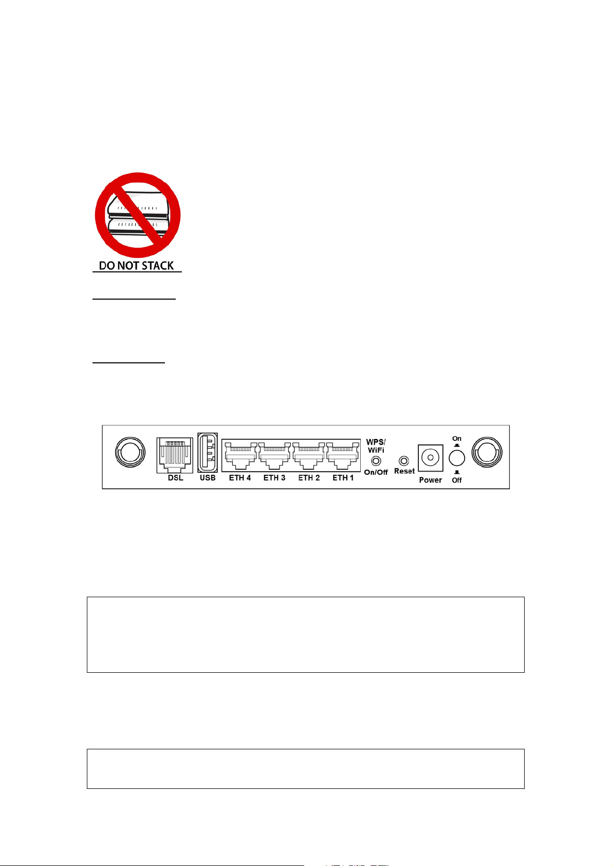
BACK PANEL
The figure below shows the back panel of the device.
Power ON
Press the power button to the OFF position (OUT). Connect the power adapter to the
power port. Attach the power adapter to a wall outlet or other AC source. Press the
power button to the ON position (IN). If the Power LED displays as expected then
the device is ready for setup (see section 2.2 LED Indicators).
Caution 1: If the device fails to power up, or it malfunctions, first verify that the
power cords are connected securely and then power it on again. If the
problem persists, contact technical support.
Caution 2: Before servicing or disassembling this equipment, disconnect all power
cords and telephone lines from their outlets.
Reset Button
Restore the default parameters of the device by pressing the Reset button for 10
seconds. After the device has rebooted successfully, the front panel should display
as expected (see section 2.2 LED Indicators for details).
NOTE: If pressed down for more than 60 seconds, the VR-3031u will go into a
firmware update state (CFE boot mode). The firmware can then be
updated using an Internet browser pointed to the default IP address.
7
Page 9

WPS/WiFi Button
Press and release WPS-WiFi button to activate WPS (make sure the WPS is enabled
in Wireless->Security page).
Press and hold WPS-WIFI button more than 5 seconds to enable/disable WiFi.
Ethernet (LAN) Ports
Use 10/100 BASE-T RJ-45 cables to connect up to four network devices. These ports
are auto-sensing MDI/X; so either straight-through or crossover cable can be used.
USB Host Port (Type A)
This port can be used to connect the router to the print server.
DSL Port
Connect to an ADSL2/2+ or VDSL with this RJ11 Port. This device contains a micro
filter which removes the analog phone signal. If you wish, you can connect a
regular telephone to the same line by using a POTS splitter.
8
Page 10
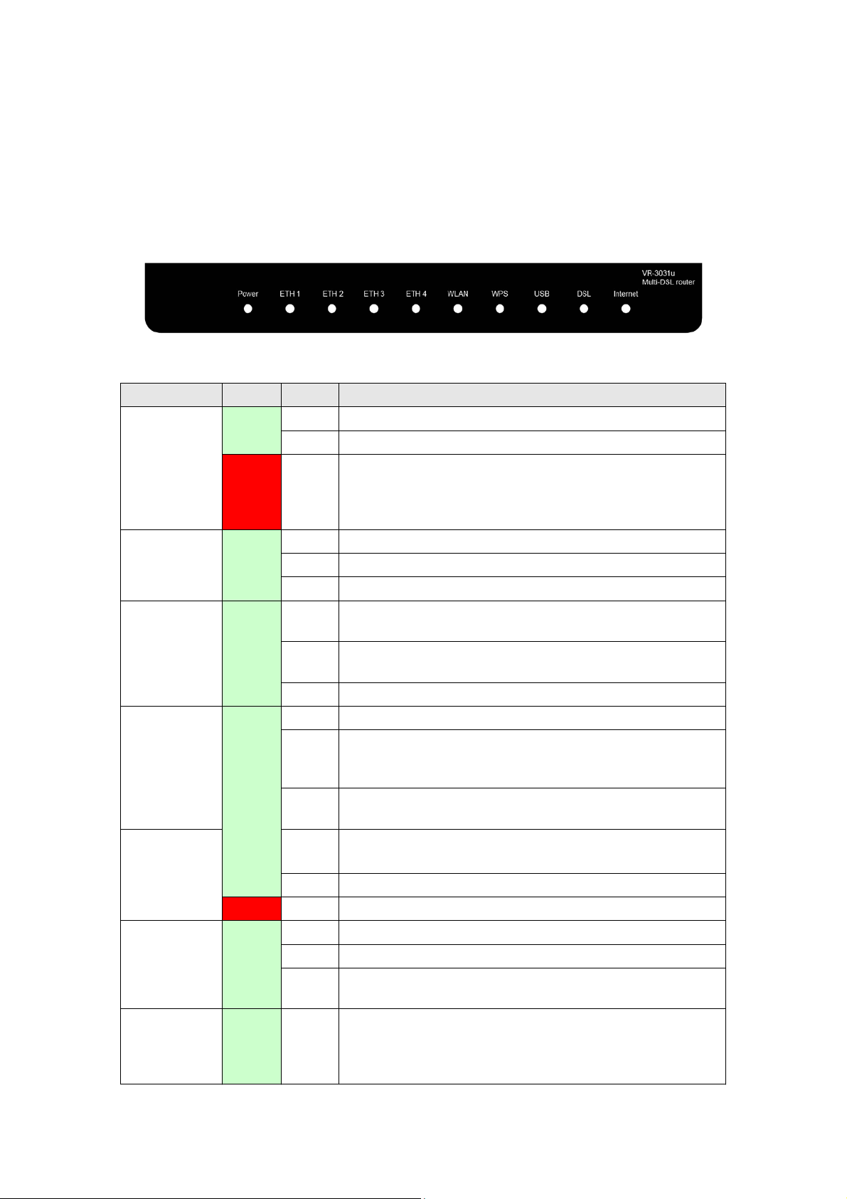
2.2 LED Indicators
The front panel LED indicators are shown below and explained in the following table.
This information can be used to check the status of the device and its connections.
LED Color Mode Function
Green
POWER
Red On
ETH 1 to 4 Green
WLAN Green
WPS Green
USB
DSL Green
INTERNET
Green
Red On USB dongle attached, connection is DOWN.
Green
On The device is powered up.
Off The device is powered down.
POST (Power On Self Test) failure or other
malfunction. A malfunction is any error of internal
sequence or state that will prevent the device from
connecting to the DSLAM or passing customer data.
On An Ethernet Link is established.
Off An Ethernet Link is not established.
Blink Data transmitting or receiving over LAN.
On The wireless module is ready.
(i.e. installed and enabled).
Off
Blink Data transmitting or receiving over WLAN.
On WPS enabled and PC connected to WLAN.
Off
Blink The router is searching for WPS clients or WPS is
On USB mass storage, USB hub or USB printer is
Off No USB device connected.
On xDSL Link is established.
Off xDSL Link is not established.
Blink fast: xDSL Link is training or data transmitting.
On IP connected and no traffic detected. If an IP or
The wireless module is not ready.
(i.e. either not installed or disabled).
WPS disenabled when WPS configured.
After clients are connected to router for about 5
minutes, LED is OFF.
un-confi
connected; or
slow: xDSL training failed.
PPPoE session is dropped due to an idle timeout, the
light will remain green if an ADSL connection is still
present.
gured.
USB dongle connection is UP.
9
Page 11

Off Modem power off, modem in bridged mode or ADSL
g
Blink IP connected and IP Traffic is passing thru the device
Red On
connection not present. In addition, if an IP or
PPPoE session is dropped for any reason, other than
an idle timeout, the li
(either direction)
Device attempted to become IP connected and failed
(no DHCP response, no PPPoE response, PPPoE
authentication failed, no IP address from IPCP, etc.)
ht is turned off.
10
Page 12

Chapter 3 Web User Interface
This section describes how to access the device via the web user interface (WUI)
using an Internet browser such as Internet Explorer (version 5.0 and later).
3.1 Default Settings
The factory default settings of this device are summarized below.
x LAN IP address: 192.168.1.1
x LAN subnet mask: 255.255.255.0
x Administrative access (username: root, password: 12345)
x User access (username: user, password: user)
x Remote (WAN) access (username: support, password: support)
x WLAN access: enabled
Technical Note
During power on, the device initializes all settings to default values. It will then
read the configuration profile from the permanent storage section of flash memory.
The default attributes are overwritten when identical attributes with different values
are configured. The configuration profile in permanent storage can be created via
the web user interface or telnet user interface, or other management protocols.
The factory default configuration can be restored either by pushing the reset button
for more than ten seconds until the power indicates LED blinking or by clicking the
Restore Default Configuration option in the Restore Settings screen.
11
Page 13
3.2 IP Configuration
DHCP MODE
When the VR-3031u powers up, the onboard DHCP server will switch on. Basically,
the DHCP server issues and reserves IP addresses for LAN devices, such as your PC.
To obtain an IP address from the DCHP server, follow the steps provided below.
NOTE: The following procedure assumes you are running Windows XP.
However, the general steps involved are similar for most operating
systems (OS). Check your OS support documentation for further details.
STEP 1: From the Network Connections window, open Local Area Connection (You
may also access this screen by double-clicking the Local Area Connection
icon on your taskbar). Click the Properties button.
STEP 2: Select Internet Protocol (TCP/IP) and click the Properties button.
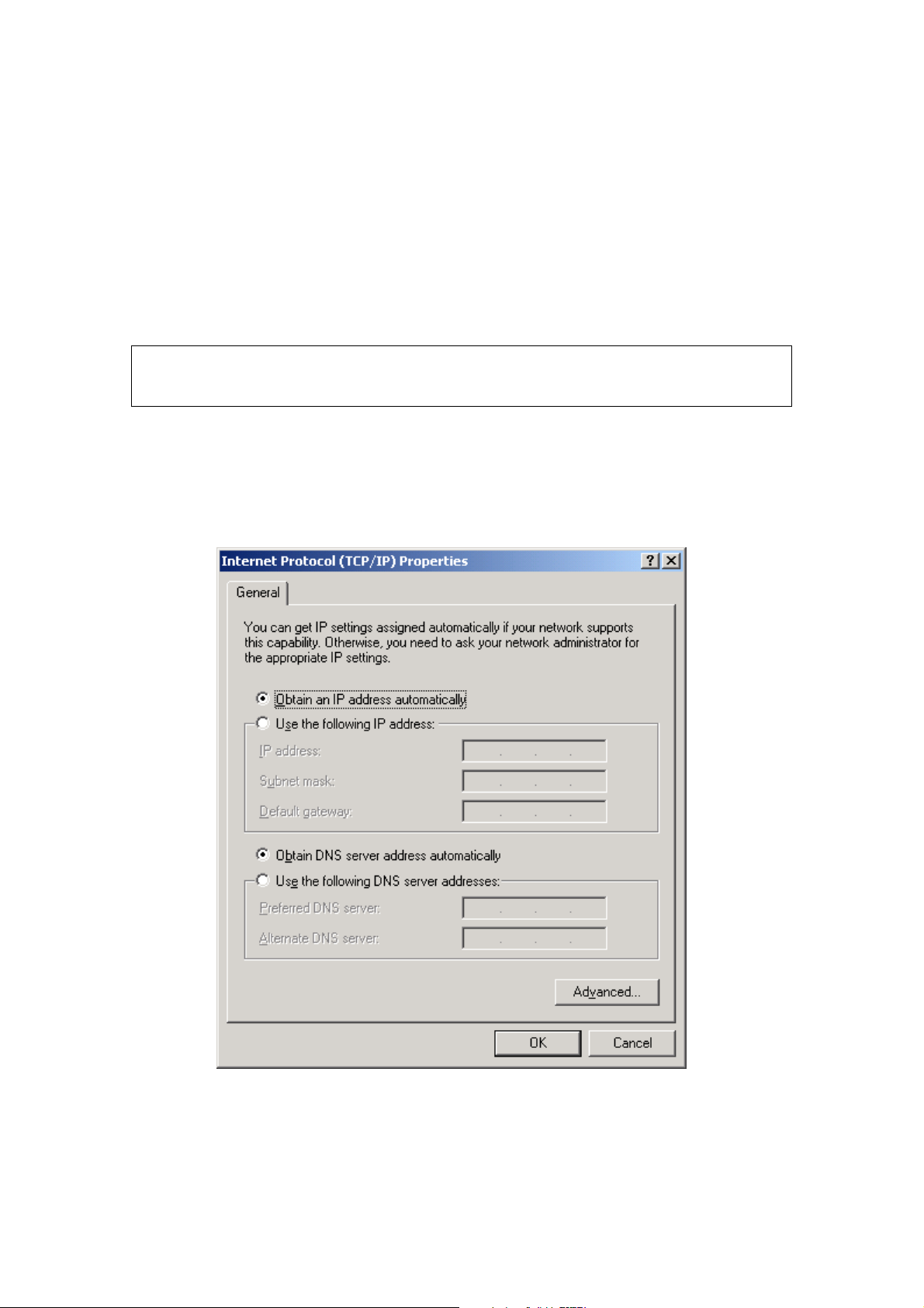
STEP 3: Select Obtain an IP address automatically as shown below.
STEP 4: Click OK to submit these settings.
If you experience difficulty with DHCP mode, you can try static IP mode instead.
12
Page 14
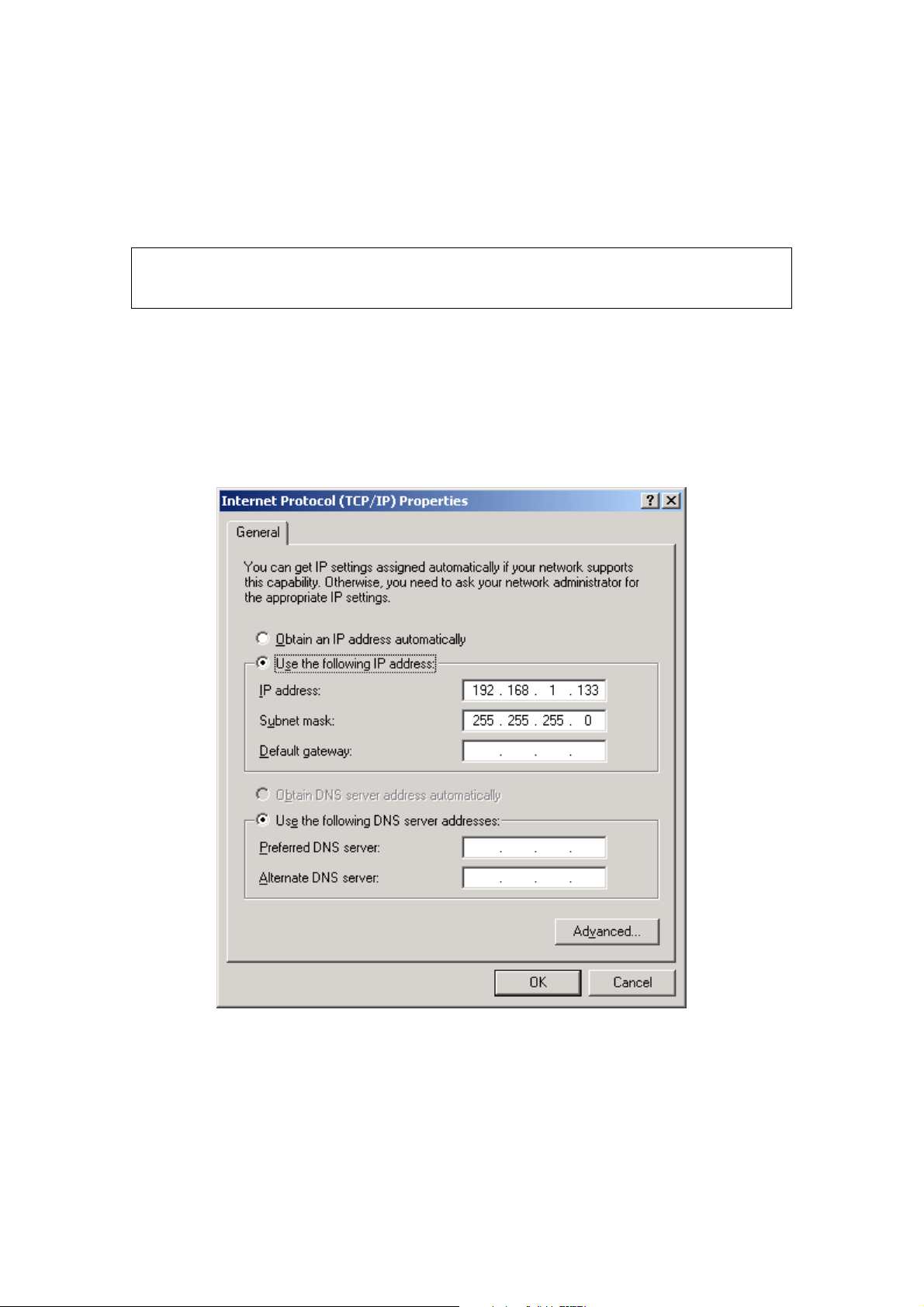
STATIC IP MODE
In static IP mode, you assign IP settings to your PC manually.
Follow these steps to configure your PC IP address to use subnet 192.168.1.x.
NOTE: The following procedure assumes you are running Windows XP.
However, the general steps involved are similar for most operating
systems (OS). Check your OS support documentation for further details.
STEP 1: From the Network Connections window, open Local Area Connection (You
may also access this screen by double-clicking the Local Area Connection
icon on your taskbar). Click the Properties button.
STEP 2: Select Internet Protocol (TCP/IP) and click the Properties button.
STEP 3: Change the IP address to the 192.168.1.x (1<x<255) subnet with subnet
mask of 255.255.255.0. The screen should now display as shown below.
STEP 4: Click OK to submit these settings.
13
Page 15
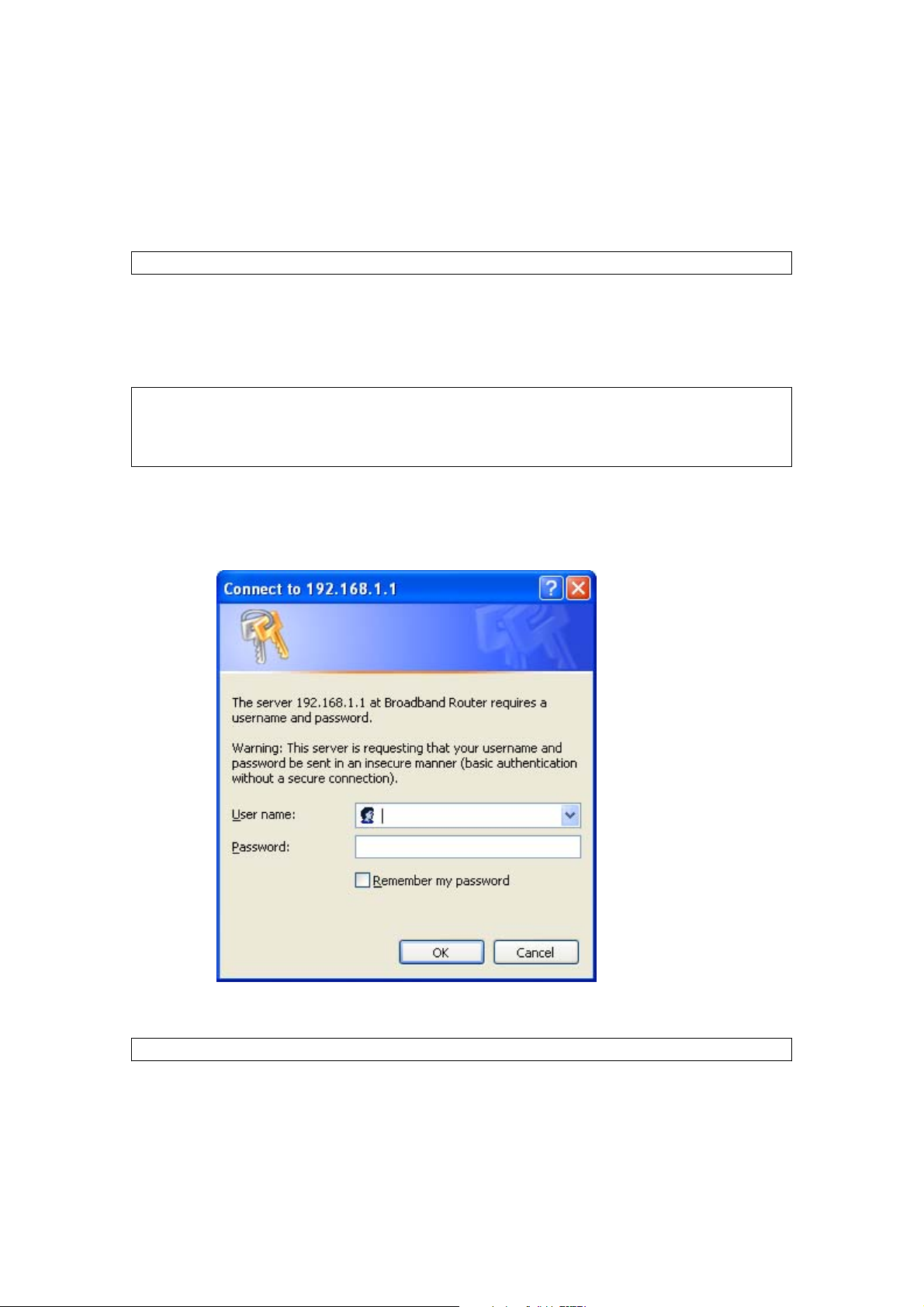
3.3 Login Procedure
Perform the following steps to login to the web user interface.
NOTE: The default settings can be found in section 3.1 Default Settings
STEP 1: Start the Internet browser and enter the default IP address for the device
in the Web address field. For example, if the default IP address is
192.168.1.1, type http://192.168.1.1.
NOTE: For local administration (i.e. LAN access), the PC running the browser
must be attached to the Ethernet, and not necessarily to the device.
For remote access (i.e. WAN), use the IP address shown on the Device
Information screen and login with remote username and password.
STEP 2: A dialog box will appear, such as the one below. Enter the default
username and password, as defined in section 3.1 Default Settings.
.
Click OK to continue.
NOTE: The login password can be changed later (see section 8.6.1 Passwords).
14
Page 16
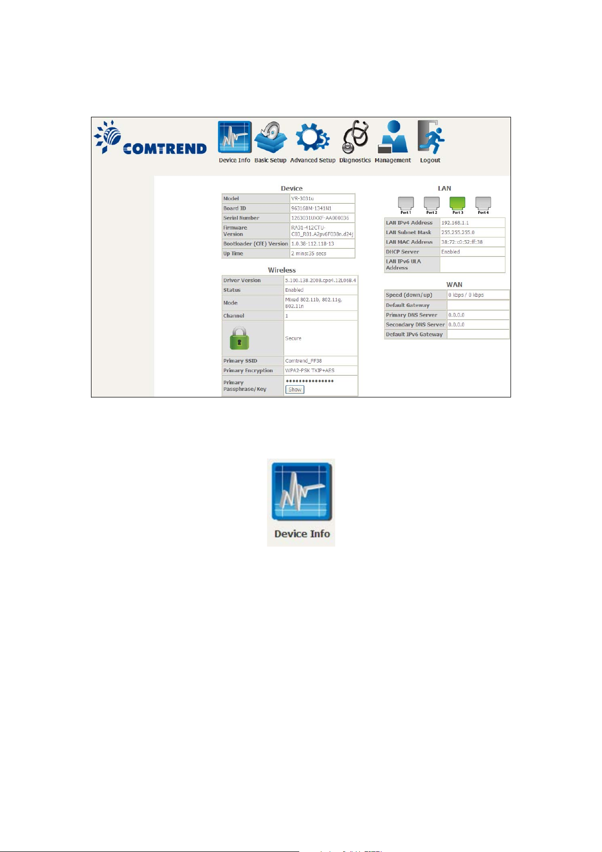
STEP 3: After successfully logging in for the first time, you will reach this screen.
You can also reach this page by clicking on the following icon located at the top of
the screen.
15
Page 17
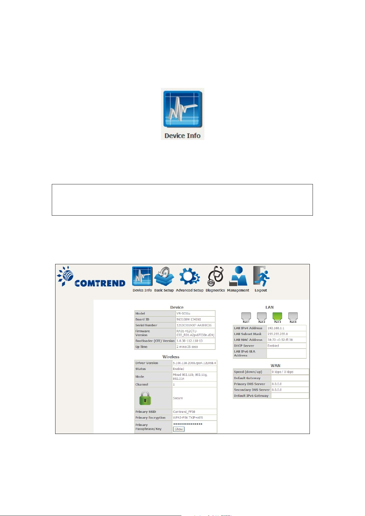
Chapter 4 Device Information
You can reach this page by clicking on the following icon located at the top of the
screen.
The web user interface window is divided into two frames, the main menu (at left)
and the display screen (on the right). The main menu has several options and
selecting each of these options opens a submenu with more selections.
NOTE: The menu items shown are based upon the configured connection(s) and
user account privileges. For example, if NAT and Firewall are enabled, the
main menu will display the NAT and Security submenus. If either is
disabled, their corresponding menu(s) will also be disabled.
Device Info is the first selection on the main menu so it will be discussed first.
Subsequent chapters will introduce the other main menu options in sequence.
The Device Info Summary screen displays at startup.
This screen shows hardware, software, IP settings and other related information.
16
Page 18
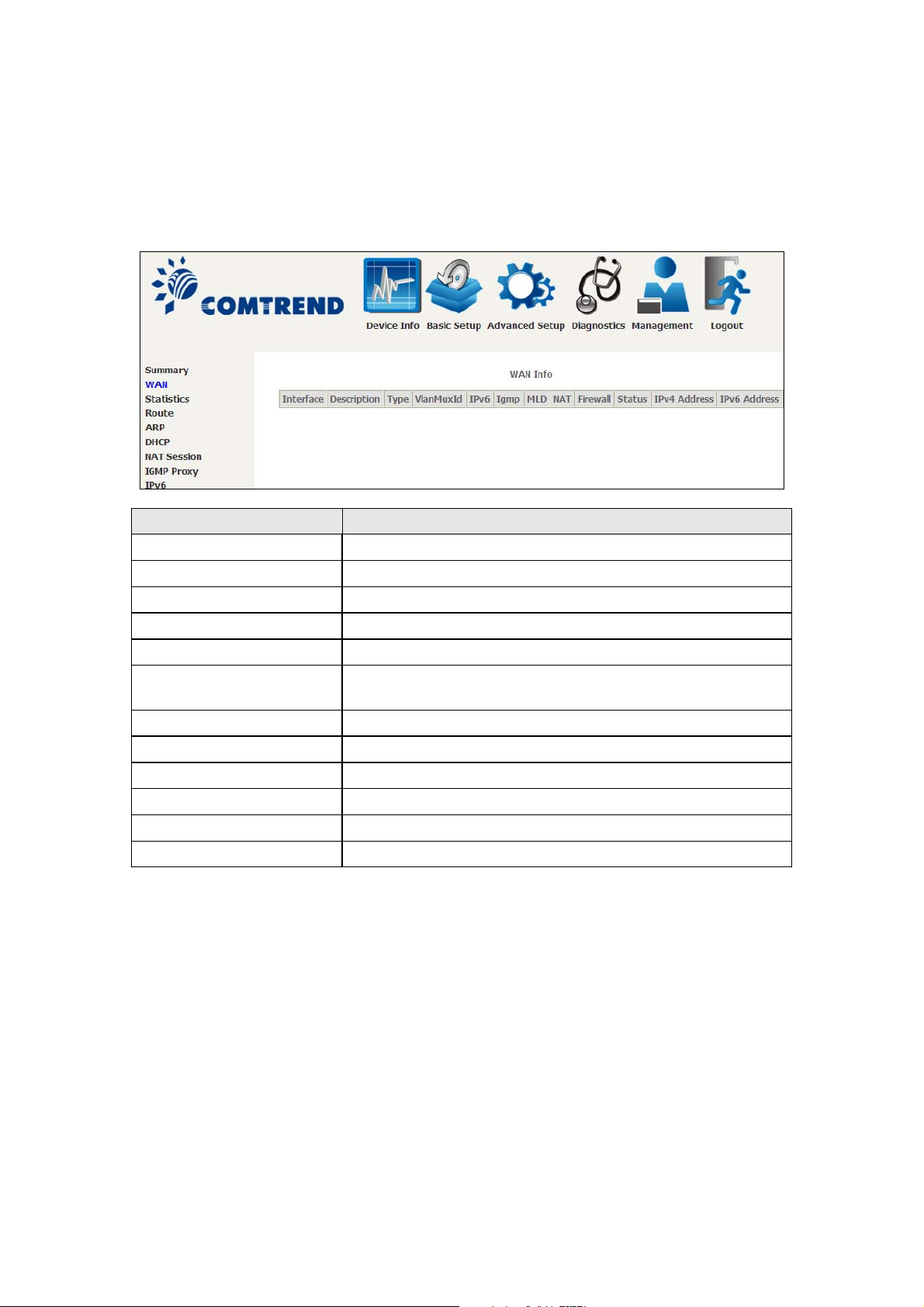
4.1 WAN
g
Select WAN from the Device Info submenu to display the configured PVC(s).
Headin
Interface Name of the interface for WAN
Description Name of the WAN connection
Type Shows the connection type
VlanMuxId Shows 802.1Q VLAN ID
IPv6 Shows WAN IPv6 status
IGMP Shows Internet Group Management Protocol (IGMP)
MLD Shows Multicast Listener Discovery (MLD) status
NAT Shows Network Address Translation (NAT) status
Firewall Shows the status of Firewall
Status Lists the status of DSL link
IPv4 Address Shows WAN IPv4 address
IPv6 Address Shows WAN IPv6 address
Description
status
17
Page 19
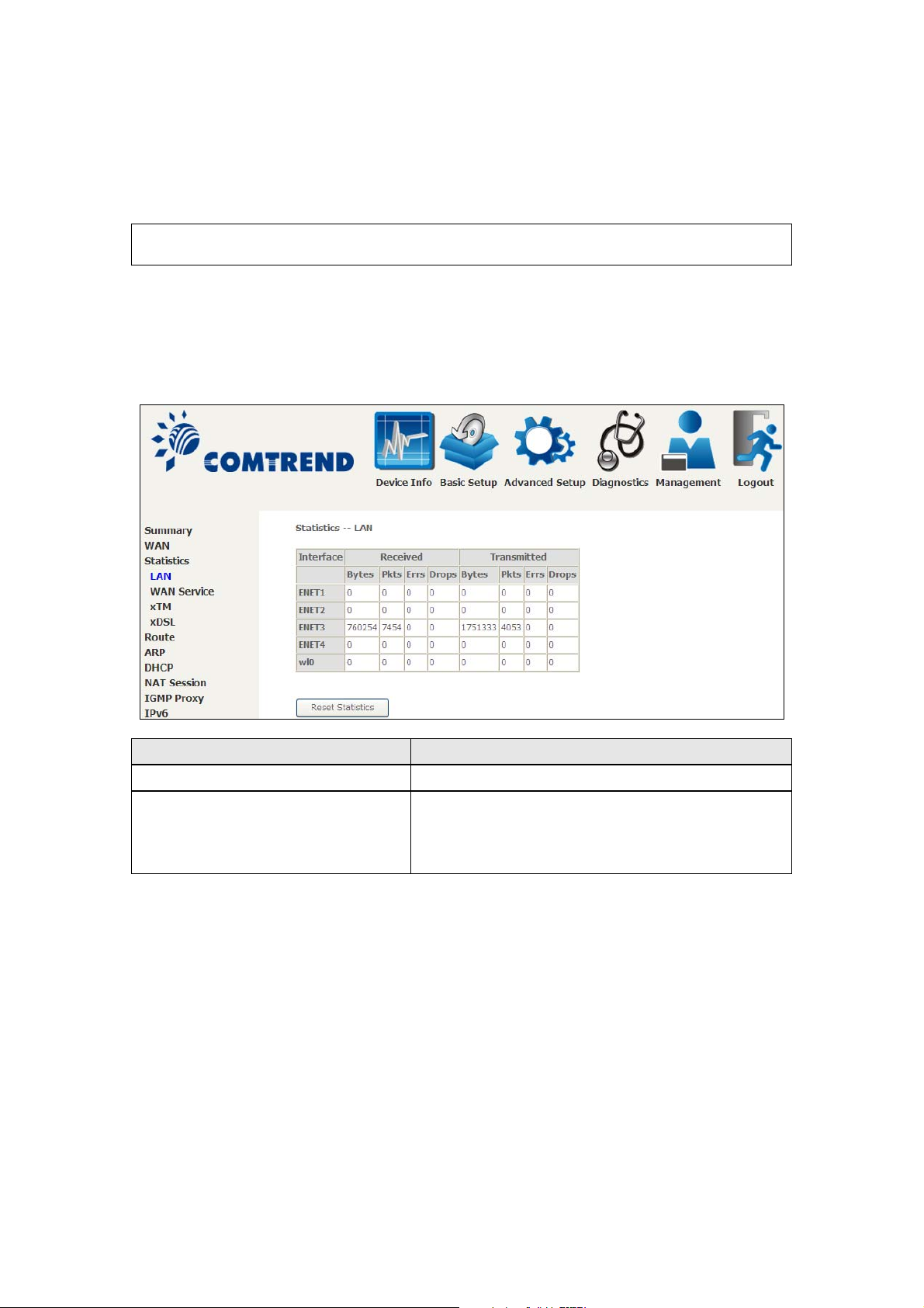
4.2 Statistics
g
This selection provides LAN, WAN, ATM and xDSL statistics.
NOTE: These screens are updated automatically every 15 seconds.
Click Reset Statistics to perform a manual update.
4.2.1 LAN Statistics
This screen shows data traffic statistics for each LAN interface.
Headin
Interface LAN interface(s)
Received/Transmitted: - Bytes
-Pkts
-Errs
-Drops
Description
Number of Bytes
Number of Packets
Number of packets with errors
Number of dropped packets
18
Page 20
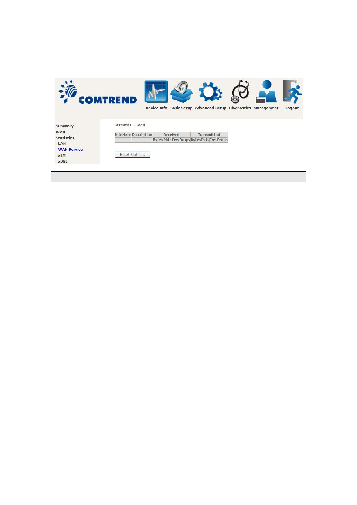
4.2.2 WAN Service
This screen shows data traffic statistics for each WAN interface.
Heading Description
Interface WAN interfaces
Description WAN service label
Received/Transmitted - Bytes
- Pkts
- Errs
- Drops
Number of Bytes
Number of Packets
Number of packets with errors
Number of dropped packets
19
Page 21
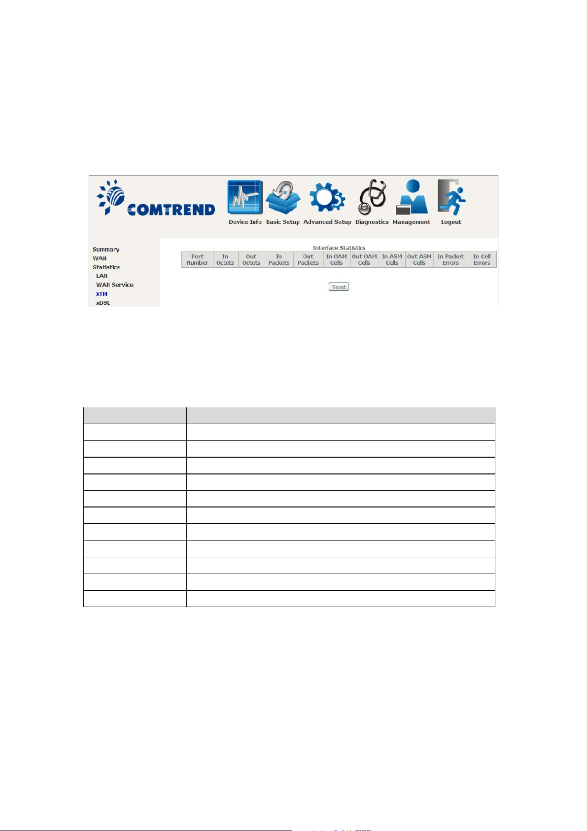
4.2.3 XTM Statistics
g
The following figure shows ATM (Asynchronous Transfer Mode)/PTM(Packet Transfer
Mode) statistics.
ATM Interface Statistics
Headin
Port Number ATM PORT (0-3)
In Octets Number of octets received over the interface
Out Octets Number of octets transmitted over the interface
In Packets Number of packets received over the interface
Out Packets Number of packets transmitted over the interface
In OAM Cells Number of OAM Cells received over the interface
Out OAM Cells Number of OAM Cells transmitted over the interface
In ASM Cells Number of ASM Cells received over the interface
Out ASM Cells Number of ASM Cells transmitted over the interface
In Packet Errors Number of packets in Error
In Cell Errors Number of cells in Error
Description
20
Page 22
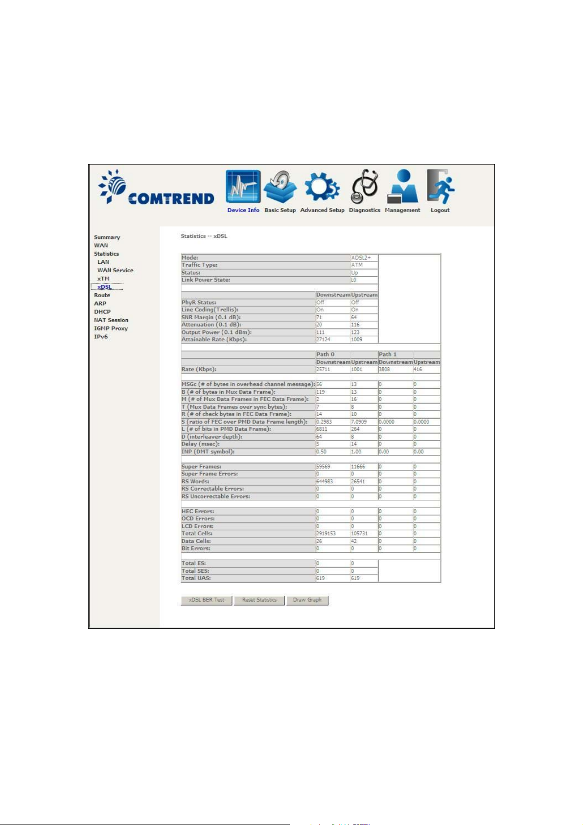
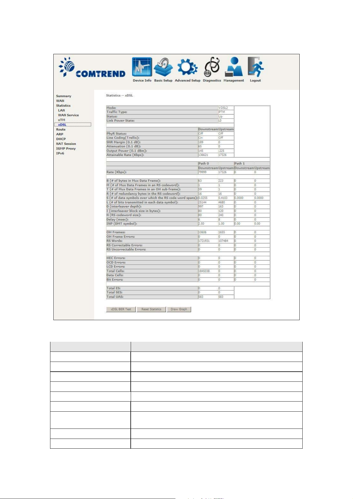
4.2.4 xDSL Statistics
The xDSL Statistics screen displays information corresponding to the xDSL type.
The two examples below (VDSL & ADSL) show this variation.
VDSL
21
Page 23
ADSL
Click the Reset Statistics button to refresh this screen.
Field Description
Mode G.Dmt, G.lite, T1.413, ADSL2, ADSL2+
Traffic Type Channel type Interleave or Fast
Status Lists the status of the DSL link
Link Power State Link output power state
Line Coding(Trellis) Trellis On/Off
SNR Margin (0.1 dB) Signal to Noise Ratio (SNR) margin
Attenuation (0.1 dB) Estimate of average loop attenuation in the downstream
direction
Output Power (0.1 dBm) Total upstream output power
Attainable Rate (Kbps) The sync rate you would obtain
22
Page 24

Field Description
g
Rate (Kbps) Current sync rates downstream/upstream
In VDSL mode, the following section is inserted.
B Number of bytes in Mux Data Frame
M Number of Mux Data Frames in a RS codeword
T Number of Mux Data Frames in an OH sub-frame
R Number of redundancy bytes in the RS codeword
S Number of data symbols the RS codeword spans
L Number of bits transmitted in each data symbol
D The interleaver depth
I The interleaver block size in bytes
N RS codeword size
Delay The delay in milliseconds (msec)
INP DMT symbol
In ADSL2+ mode, the following section is inserted.
MSGc Number of bytes in overhead channel messa
B Number of bytes in Mux Data Frame
M Number of Mux Data Frames in FEC Data Frame
T Mux Data Frames over sync bytes
R Number of check bytes in FEC Data Frame
S Ratio of FEC over PMD Data Frame length
L Number of bits in PMD Data Frame
D The interleaver depth
Delay The delay in milliseconds (msec)
INP DMT symbol
In G.DMT mode, the following section is inserted.
K Number of bytes in DMT frame
R Number of check bytes in RS code word
S RS code word size in DMT frame
D The interleaver depth
Delay The delay in milliseconds (msec)
e
Super Frames Total number of super frames
Super Frame Errors Number of super frames received with errors
RS Words Total number of Reed-Solomon code errors
RS Correctable Errors Total Number of RS with correctable errors
RS Uncorrectable Errors Total Number of RS words with uncorrectable errors
23
Page 25

HEC Errors Total Number of Header Error Checksum errors
OCD Errors Total Number of Out-of-Cell Delineation errors
LCD Errors Total number of Loss of Cell Delineation
Total Cells Total number of ATM cells (including idle + data cells)
Data Cells Total number of ATM data cells
Bit Errors Total number of bit errors
Total ES Total Number of Errored Seconds
Total SES Total Number of Severely Errored Seconds
Total UAS Total Number of Unavailable Seconds
xDSL BER TEST
Click xDSL BER Test on the xDSL Statistics screen to test the Bit Error Rate (BER).
A small pop-up window will open after the button is pressed, as shown below.
Click Start to start the test or click Close to cancel the test. After the BER testing is
complete, the pop-up window will display as follows.
24
Page 26
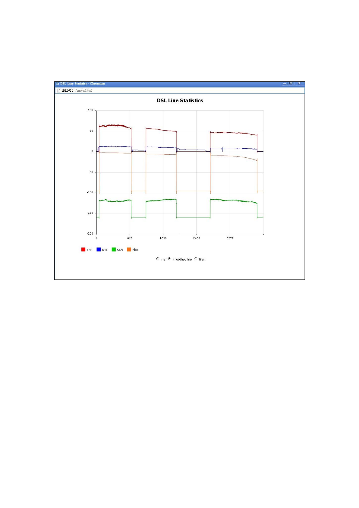
xDSL TONE GRAPH
Click Draw Tone Graph on the xDSL Statistics screen and a pop-up window will
display the xDSL bits per tone status, as shown below.
25
Page 27
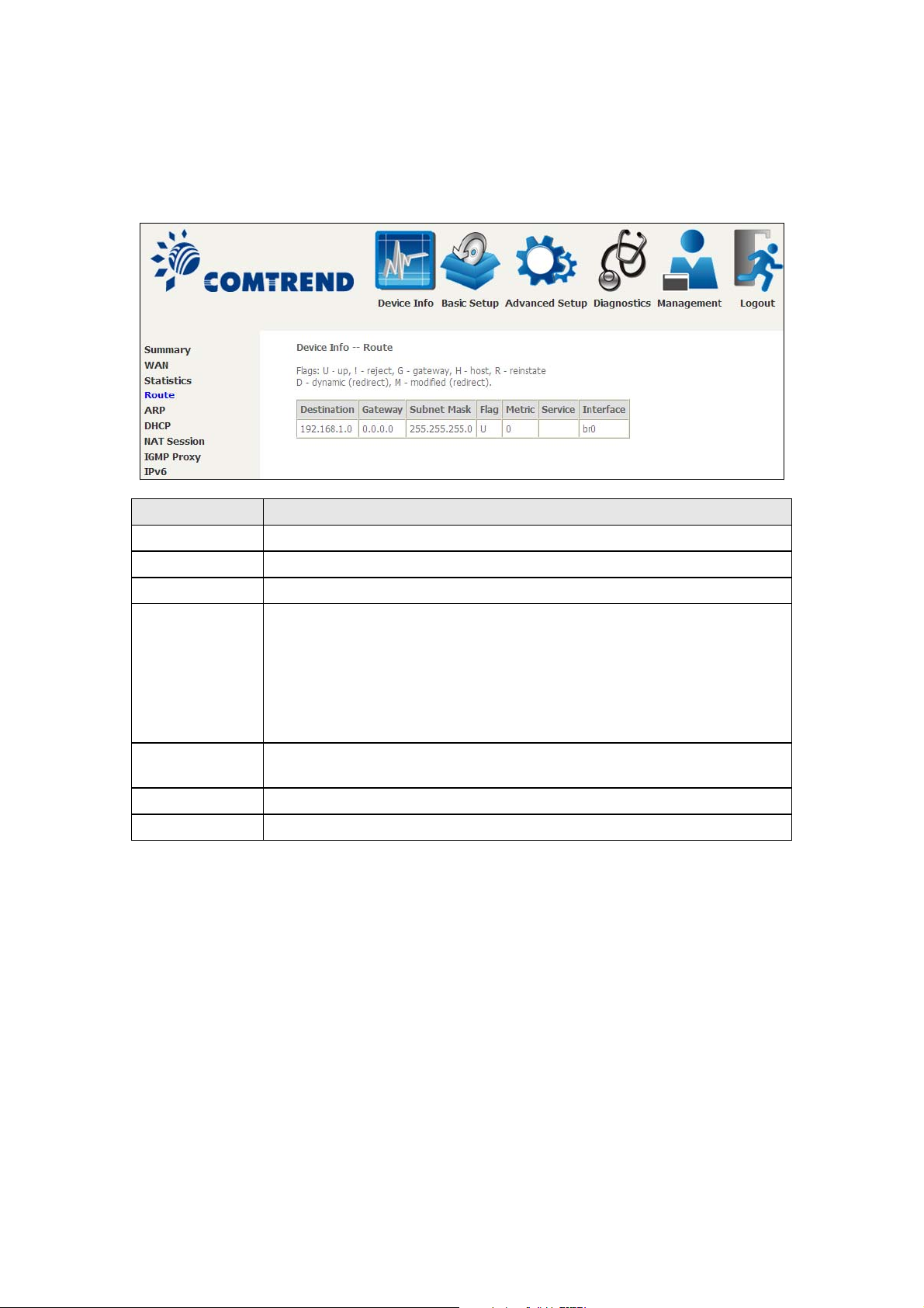
4.3 Route
Choose Route to display the routes that the VR-3031u has found.
Field Description
Destination Destination network or destination host
Gateway Next hop IP address
Subnet Mask Subnet Mask of Destination
Flag U: route is up
!: reject route
G: use gateway
H: target is a host
R: reinstate route for dynamic routing
D: dynamically installed by daemon or redirect
M: modified from routing daemon or redirect
Metric The 'distance' to the target (usually counted in hops). It is not
used by recent kernels, but may be needed by routing daemons.
Service Shows the WAN connection label
Interface Shows connection interfaces
26
Page 28
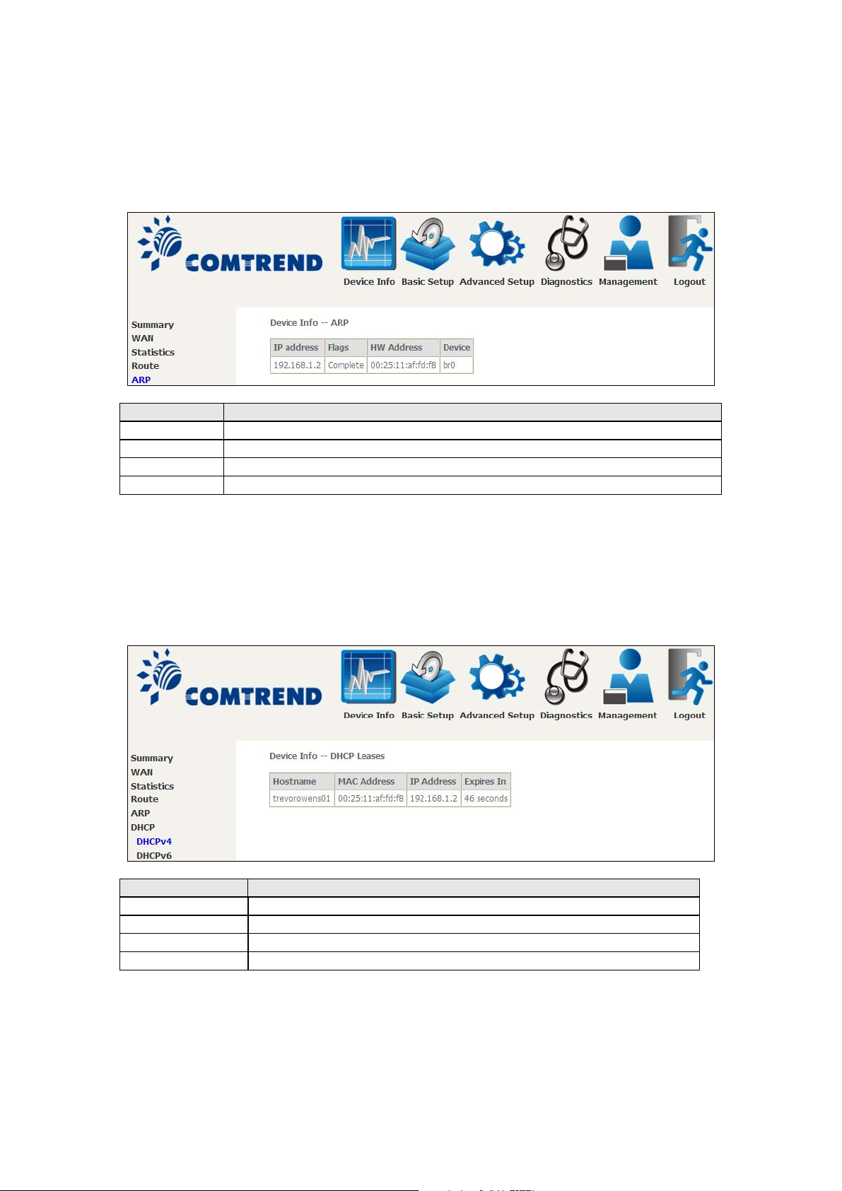
4.4 ARP
Click ARP to display the ARP information.
Field Description
IP address Shows IP address of host pc
Flags Complete, Incomplete, Permanent, or Publish
HW Address Shows the MAC address of host pc
Device Shows the connection interface
4.5 DHCP
Click DHCP to display all DHCP Leases.
Field Description
IPv6 Address Shows IP address of device/host/PC
MAC Address Shows the Ethernet MAC address of the device/host/PC
IP Address Shows IP address of device/host/PC
Expires In Shows how much time is left for each DHCP Lease
27
Page 29
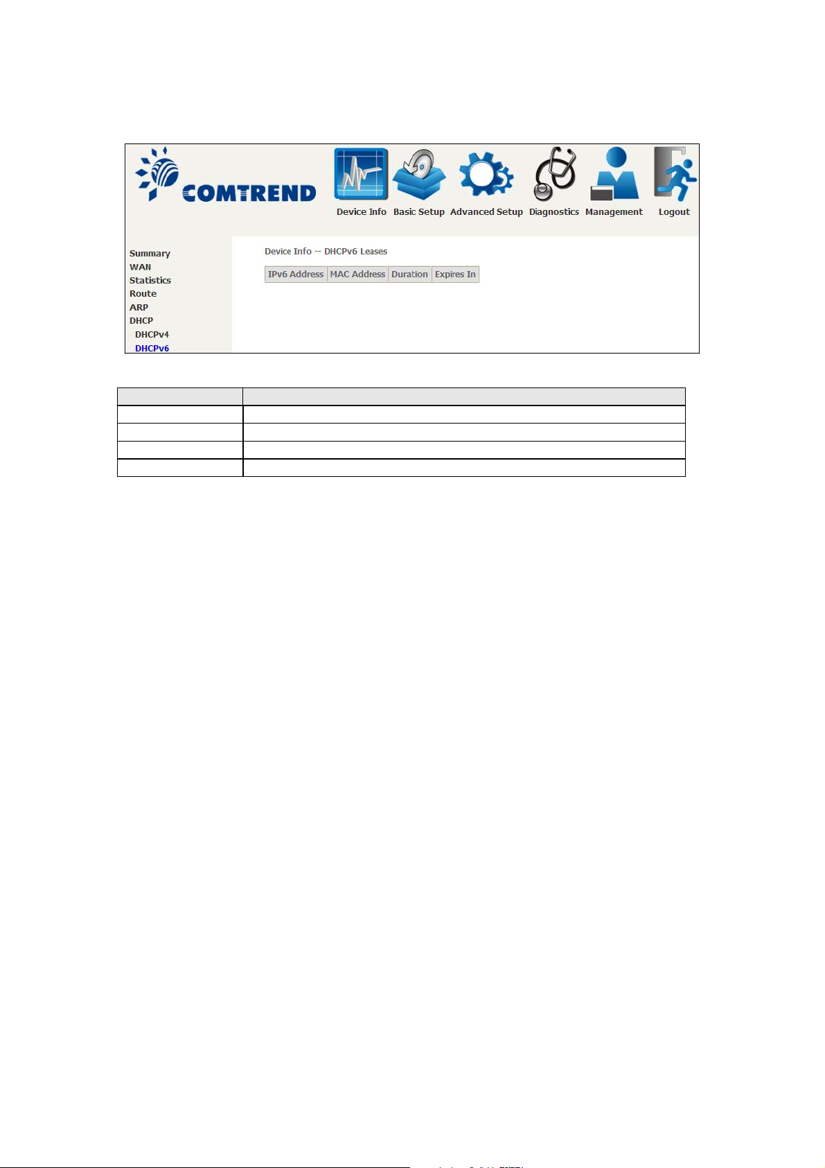
Field Description
IPv6 Address Shows IP address of device/host/PC
MAC Address Shows the Ethernet MAC address of the device/host/PC
Duration Shows leased time in hours
Expires In Shows how much time is left for each DHCP Lease
28
Page 30
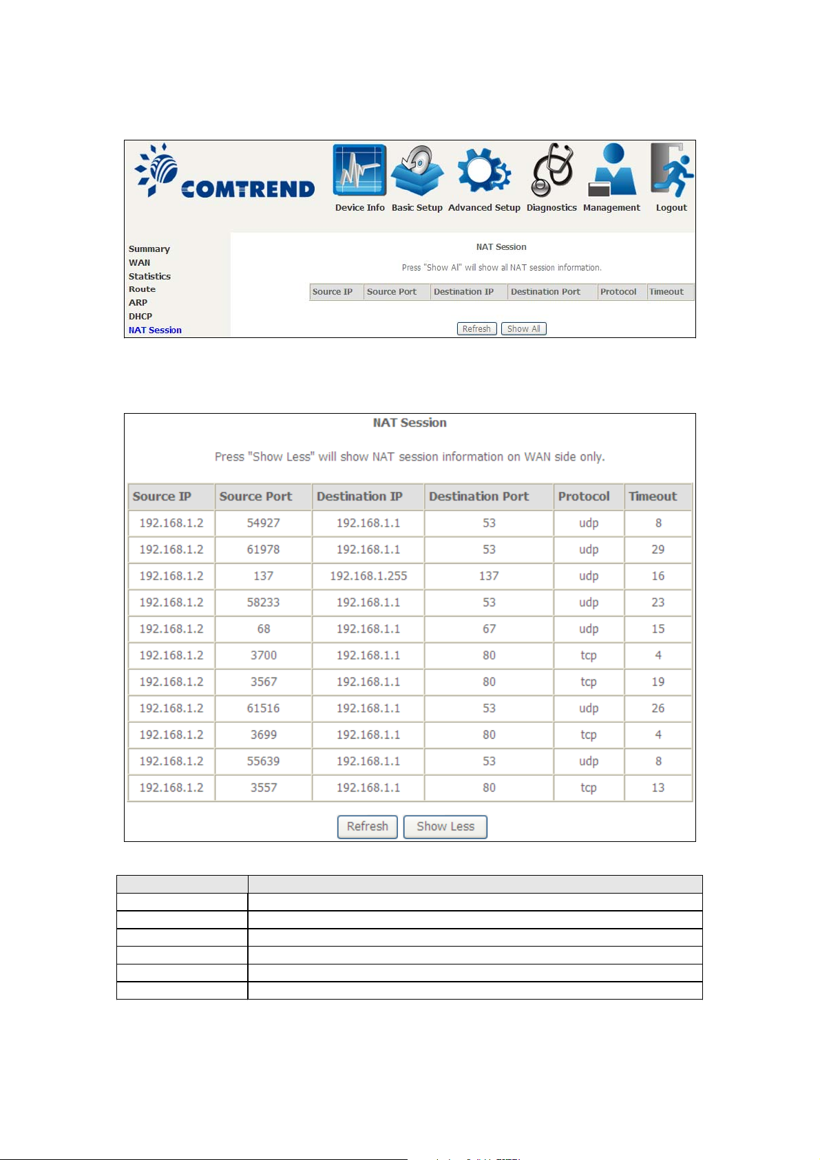
4.6 NAT Session
Click the “Show All” button to display the following.
Field Description
Source IP The source IP from which the NAT session is established
Source Port The source port from which the NAT session is established
Destination IP The IP which the NAT session was connected to
Destination Port The port which the NAT session was connected to
Protocol The Protocol used in establishing the particular NAT session
Timeout The time remaining for the TCP/UDP connection to be active
29
Page 31

4.7 IGMP Proxy
Field Description
Interface The Source interface from which the IGMP report was received
WAN The WAN interface from which the multicast traffic is received
Groups The destination IGMP group address
Member The Source IP from which the IGMP report was received
Timeout The time remaining before the IGMP report expires
30
Page 32

4.8 IPv6
4.8.1 IPv6 Info
Field Description
Interface WAN interface with IPv6 enabled
Status Connection status of the WAN interface
Address IPv6 Address of the WAN interface
Prefix Prefix received/configured on the WAN interface
Device Link-local Address The CPE's LAN Address
Default IPv6 Gateway The default WAN IPv6 gateway
IPv6 DNS Server The IPv6 DNS servers received from the WAN interface
/configured manually
31
Page 33

4.8.2 IPv6 Neighbor
Field Description
IPv6 Address Ipv6 address of the device(s) found
Flags Status of the neighbor device
HW Address MAC address of the neighbor device
Device Interface from which the device is located
32
Page 34

4.8.3 IPv6 Route
Field Description
Destination Destination IP Address
Gateway Gateway address used for destination IP
Metric Metric specified for gateway
Interface Interface used for destination IP
33
Page 35

4.8.4 Network Map
The network map is a graphical representation of router’s wan status and LAN
devices. The feature is only available using a non-IE browser.
34
Page 36

Chapter 5 Basic Setup
You can reach this page by clicking on the following icon located at the top of the
screen.
5.1 Layer 2 Interface
Add or remove ATM, PTM and ETH WAN interface connections here.
Click Add to create a new ATM interface (see Appendix E - Connection Setup).
NOTE: Up to 8 ATM interfaces can be created and saved in flash memory.
To remove a connection, select its Remove column radio button and click Remove.
35
Page 37

5.1.1 WAN Service Setup
This screen allows for the configuration of WAN interfaces.
Click the Add button to create a new connection. For connections on ATM or ETH
WAN interfaces see Appendix E - Connection Setup.
To remove a connection, select its Remove column radio button and click Remove.
Heading Description
Interface Name of the interface for WAN
Description Name of the WAN connection
Type Shows the connection type
Vlan8021p VLAN ID is used for VLAN Tagging (IEEE 802.1Q)
VlanMuxId Shows 802.1Q VLAN ID
IGMP Shows Internet Group Management Protocol (IGMP) status
NAT Shows Network Address Translation (NAT) status
Firewall Shows the Security status
IPv6 Shows the WAN IPv6 address
MLD Shows Multicast Listener Discovery (MLD) status
Remove Select interfaces to remove
To remove a connection, select its Remove column radio button and click Remove.
NOTE: ETH and ATM service connections cannot coexist. In Default Mode, up to
8 WAN connections can be configured; while VLAN Mux Connection Mode
supports up to 16 WAN connections.
NOTE: Up to 16 PVC profiles can be configured and saved in flash memory.
Also, ETH and PTM/ATM service connections cannot coexist.
36
Page 38

5.2 NAT
To display this option, NAT must be enabled in at least one PVC. NAT is not an
available option in Bridge mode.
5.2.1 Virtual Servers
Virtual Servers allow you to direct incoming traffic from the WAN side (identified by
Protocol and External port) to the internal server with private IP addresses on the
LAN side. The Internal port is required only if the external port needs to be
converted to a different port number used by the server on the LAN side.
A maximum of 32 entries can be configured.
To add a Virtual Server, click Add. The following will be displayed.
37
Page 39

Consult the table below for field and header descriptions.
Field/Header Description
Use Interface Select a WAN interface from the drop-down box.
Select a Service
Or
Custom Service
Server IP Address Enter the IP address for the server.
Enable NAT
Loopback
External Port Start Enter the starting external port number (when you select
External Port End Enter the ending external port number (when you select
Protocol TC P, T C P/ U D P, o r U D P.
Internal Port Start Enter the internal port starting number (when you select
Internal Port End Enter the internal port ending number (when you select
User should select the service from the list.
Or
User can enter the name of their choice.
Allows local machines to access virtual server via WAN IP
Address
Custom Server). When a service is selected, the port ranges
are automatically configured.
Custom Server). When a service is selected, the port ranges
are automatically configured.
Custom Server). When a service is selected the port ranges
are automatically configured
Custom Server). When a service is selected, the port ranges
are automatically configured.
5.2.2 Port Triggering
Some applications require that specific ports in the firewall be opened for access by
the remote parties. Port Triggers dynamically 'Open Ports' in the firewall when an
application on the LAN initiates a TCP/UDP connection to a remote party using the
'Triggering Ports'. The Router allows the remote party from the WAN side to
establish new connections back to the application on the LAN side using the 'Open
Ports'. A maximum 32 entries can be configured.
To add a Trigger Port, click Add. The following will be displayed.
38
Page 40

Click Save/Apply to save and apply the settings.
Consult the table below for field and header descriptions.
Field/Header Description
Use Interface Select a WAN interface from the drop-down box.
Select an Application
Or
Custom Application
Trigger Port Start Enter the starting trigger port number (when you select
Trigger Port End Enter the ending trigger port number (when you select
Trigger Protocol T CP, T CP / U D P, o r U D P.
Open Port Start Enter the starting open port number (when you select
Open Port End Enter the ending open port number (when you select
Open Protocol T C P, T C P/ U D P, o r U D P.
User should select the application from the list.
Or
User can enter the name of their choice.
custom application). When an application is selected, the
port ranges are automatically configured.
custom application). When an application is selected, the
port ranges are automatically configured.
custom application). When an application is selected, the
port ranges are automatically configured.
custom application). When an application is selected, the
port ranges are automatically configured.
39
Page 41

5.2.3 DMZ Host
The DSL router will forward IP packets from the WAN that do not belong to any of
the applications configured in the Virtual Servers table to the DMZ host computer.
To Activate the DMZ host, enter the DMZ host IP address and click Save/Apply.
To Deactivate the DMZ host, clear the IP address field and click Save/Apply.
Enable NAT Loopback allows PC on the LAN side to access servers in the LAN
network via the router’s WAN IP.
40
Page 42

5.2.4 IP Address Map
Mapping Local IP (LAN IP) to some specified Public IP (WAN IP).
Field/Header Description
Rule The number of the rule
Type Mapping type from local to public.
Local Start IP The beginning of the local IP
Local End IP The ending of the local IP
Public Start IP The beginning of the public IP
Public End IP The ending of the public IP
Remove Remove this rule
Click the Add button to display the following.
Select a Service, then click the Save/Apply button.
41
Page 43

One to One: mapping one local IP to a specific public IP
Many to one: mapping a range of local IP to a specific public IP
Many to many(Overload): mapping a range of local IP to a different range of
public IP
Many to many(No Overload): mapping a range of local IP to a same range of
public IP
42
Page 44

5.2.5 IPSEC ALG
IPSEC ALG provides multiple VPN passthrough connection support, allowing
different clients on LAN side to establish a secured IP Connection to the WAN server.
To enable IPSEC ALG, tick the checkbox and click the Save button.
43
Page 45

5.2.6 SIP ALG
This page allows you to enable / disable SIP ALG.
44
Page 46

5.3 LAN
Configure the LAN interface settings and then click Apply/Save.
Consult the field descriptions below for more details.
GroupName: Select an Interface Group.
st
1
LAN INTERFACE
IP Address: Enter the IP address for the LAN port.
Subnet Mask: Enter the subnet mask for the LAN port.
45
Page 47

IGMP Snooping:
Standard Mode: In standard mode, multicast traffic will flood to all
bridge ports when no client subscribes to a multicast
group – even if IGMP snooping is enabled.
Blocking Mode: In blocking mode, the multicast data traffic will be
blocked and not flood to all bridge ports when there are
no client subscriptions to any multicast group.
Enable LAN side firewall: Enable by ticking the checkbox ;.
DHCP Server: To enable DHCP, select Enable DHCP server and enter Start and
End IP addresses and the Leased Time. This setting configures the
router to automatically assign IP, default gateway and DNS server
addresses to every PC on your LAN.
Setting TFTP Server: Enable by ticking the checkbox ;. Then, input the TFTP
server address or an IP address.
Static IP Lease List: A maximum of 32 entries can be configured.
To add an entry, enter MAC address and Static IP address and then click
Apply/Save.
To remove an entry, tick the corresponding checkbox ; in the Remove column and
then click the Remove Entries button, as shown below.
46
Page 48

2NDLAN INTERFACE
To configure a secondary IP address, tick the checkbox ; outlined (in RED) below.
IP Address: Enter the secondary IP address for the LAN port.
Subnet Mask: Enter the secondary subnet mask for the LAN port.
Ethernet Media Type:
Configure auto negotiation, or enforce selected speed and duplex mode for the
Ethernet ports.
47
Page 49

5.3.1 LAN IPv6 Autoconfig
Configure the LAN interface settings and then click Save/Apply.
Consult the field descriptions below for more details.
48
Page 50

LAN IPv6 Link-Local Address Configuration
g
Heading Description
EUI-64 Use EUI-64 algorithm to calculate link-local address from MAC
address
User Setting Use the Interface Identifier field to define a link-local address
Static LAN IPv6 Address Configuration
Headin
Interface Address
(prefix length is
required):
IPv6 LAN Applications
Heading Description
Stateless Use stateless configuration
Refresh Time (sec): The information refresh time option specifies how long a
Stateful Use stateful configuration
Start interface ID: Start of interface ID to be assigned to dhcpv6 client
End interface ID: End of interface ID to be assigned to dhcpv6 client
Leased Time (hour): Lease time for dhcpv6 client to use the assigned IP address
Static IP Lease List: A maximum of 32 entries can be configured.
Description
Configure static LAN IPv6 address and subnet prefix
length
client should wait before refreshing information retrieved
from DHCPv6
To add an entry, enter MAC address and Interface ID and then click Apply/Save.
49
Page 51

To remove an entry, tick the corresponding checkbox ; in the Remove column and
then click the Remove Entries button, as shown below.
Heading Description
Enable RADVD Enable use of router advertisement daemon
RA interval Min(sec): Minimum time to send router advertisement
RA interval Max(sec): Maximum time to send router advertisement
Reachable Time(ms): The time, in milliseconds that a neighbor is
reachable after receiving reachability
confirmation
Default Preference: Preference level associated with the default
router
MTU (bytes): MTU value used in router advertisement
messages to insure that all nodes on a link use
the same MTU value
Enable Prefix Length Relay Use prefix length receive from WAN interface
Enable Configuration Mode Manually configure prefix, prefix length,
preferred lifetime and valid lifetime used in
router advertisement
Enable ULA Prefix Advertisement Allow RADVD to advertise Unique Local Address
Prefix
Randomly Generate Use a Randomly Generated Prefix
Statically Configure Prefix Specify the prefix to be used
Statically Configure The prefix to be used
Preferred Life Time (hour) The preferred life time for this prefix
Valid Life Time (hour) The valid life time for this prefix
Enable MLD Snooping Enable/disable IPv6 multicast forward to LAN
ports
50
Page 52

5.3.2 Static IP Neighbor
g
Click the Add button to display the following.
Click Apply/Save to apply and save the settings.
Headin
IP Version The IP version used for the neighbor device
IP Address Define the IP Address for the neighbor device
MAC Address The MAC Address of the neighbor device
Associated Interface The interface where the neighbor device is located
Description
51
Page 53

5.3.3 UPnP
Select the checkbox ; provided and click Apply/Save to enable UPnP protocol.
52
Page 54

5.4 Wireless
5.4.1 Basic
The Basic option allows you to configure basic features of the wireless LAN interface.
Among other things, you can enable or disable the wireless LAN interface, hide the
network from active scans, set the wireless network name (also known as SSID)
and restrict the channel set based on country requirements.
Click Apply/Save to apply the selected wireless options.
Consult the table below for descriptions of these options.
Option Description
Enable
Wireless
A checkbox ; that enables or disables the wireless LAN interface.
When selected, a set of basic wireless options will appear.
53
Page 55

Option Description
g
g
Hide Access
Point
Clients
Isolation
Disable WMM
Advertise
Enable
Wireless
Multicast
Forwardin
Enable WiFi
Button
SSID
[1-32
characters]
BSSID The BSSID is a 48-bit identity used to identify a particular BSS
Country A drop-down menu that permits worldwide and specific national
Max Clients The maximum number of clients that can access the router.
Wireless Guest /
Virtual
Access Points
Select Hide Access Point to protect the access point from detection
by wireless active scans. To check AP status in Windows XP, open
Network Connections from the start Menu and select View
Available Network Connections. If the access point is hidden, it
will not be listed there. To connect a client to a hidden access point,
the station must add the access point manually to its wireless
configuration.
When enabled, it prevents client PCs from seeing one another in My
Network Places or Network Neighborhood. Also, prevents one
wireless client communicating with another wireless client.
Stops the router from ‘advertising’ its Wireless Multimedia (WMM)
functionality, which provides basic quality of service for
time-sensitive applications (e.g. VoIP, Video).
Select the checkbox ; to enable this function.
Select the checkbox ; to enable the WiFi button.
Sets the wireless network name. SSID stands for Service Set
Identifier. All stations must be configured with the correct SSID to
access the WLAN. If the SSID does not match, that user will not be
ranted access.
(Basic Service Set) within an area. In Infrastructure BSS
networks, the BSSID is the MAC (Media Access Control) address of
the AP (Access Point); and in Independent BSS or ad hoc networks,
the BSSID is generated randomly.
settings. Local regulations limit channel range:
US= worldwide, Japan=1-14, Jordan= 10-13, Israel= 1-13
This router supports multiple SSIDs called Guest SSIDs or Virtual
Access Points. To enable one or more Guest SSIDs select the
checkboxes ; in the Enabled column. To hide a Guest SSID select
its checkbox ; in the Hidden column.
Do the same for Isolate Clients and Disable WMM Advertise.
For a description of these two functions, see the previous entries for
“Clients Isolation” and “Disable WMM Advertise”. Similarly, for
Enable WMF, Max Clients and BSSID, consult the matching
entries in this table.
NOTE: Remote wireless hosts cannot scan Guest SSIDs.
54
Page 56

5.4.2 Security
g
The following screen appears when Wireless Security is selected. The options shown
here allow you to configure security features of the wireless LAN interface.
Click Apply/Save to implement new configuration settings.
WIRELESS SECURITY
Setup requires that the user configure these settings using the Web User Interface
(see the table below).
Select SSID
Select the wireless network name from the drop-down box. SSID stands for Service
Set Identifier. All stations must be configured with the correct SSID to access the
WLAN. If the SSID does not match, that client will not be
Network Authentication
This option specifies whether a network key is used for authentication to the
wireless network. If network authentication is set to Open, then no authentication
is provided. Despite this, the identity of the client is still verified.
Each authentication type has its own settings. For example, selecting 802.1X
authentication will reveal the RADIUS Server IP address, Port and Key fields. WEP
Encryption will also be enabled as shown below.
55
ranted access.
Page 57

The settings for WPA authentication are shown below.
The settings for WPA-PSK authentication are shown next.
56
Page 58

WEP Encryption
g
This option specifies whether data sent over the network is encrypted. The same
network key is used for data encryption and network authentication. Four network
keys can be defined although only one can be used at any one time. Use the Current
Network Key list box to select the appropriate network key.
Security options include authentication and encryption services based on the wired
equivalent privacy (WEP) algorithm. WEP is a set of security services used to
protect 802.11 networks from unauthorized access, such as eavesdropping; in this
case, the capture of wireless network traffic.
When data encryption is enabled, secret shared encryption keys are generated and
used by the source station and the destination station to alter frame bits, thus
avoiding disclosure to eavesdroppers.
Under shared key authentication, each wireless station is assumed to have received
a secret shared key over a secure channel that is independent from the 802.11
wireless network communications channel.
Encryption Strength
This drop-down list box will display when WEP Encryption is enabled. The key
strength is proportional to the number of binary bits comprising the key. This
means that keys with a greater number of bits have a greater degree of security and
are considerably more difficult to crack. Encryption strength can be set to either
64-bit or 128-bit. A 64-bit key is equivalent to 5 ASCII characters or 10
hexadecimal numbers. A 128-bit key contains 13 ASCII characters or 26
hexadecimal numbers. Each key contains a 24-bit header (an initiation vector)
which enables parallel decodin
of multiple streams of encrypted data.
Please see Section 6.14 for MAC Filter, Wireless Bridge and Advanced Wireless
features.
57
Page 59

Chapter 6 Advanced Setup
You can reach this page by clicking on the following icon located at the top of the
screen.
6.1 Auto-detection setup
The auto-detection function is used for CPE to detect WAN service for either
ETHWAN or xDSL interface. The feature is designed for the scenario that requires
only one WAN service in different applications.
The Auto Detection page simply provides a checkbox allowing users to enable or
disable the feature. Check the checkbox to display the following configuration
options.
58
Page 60

Enter the PPP username/password given by your service provider for PPP service
detection.
Select a LAN-as-WAN Ethernet port for auto-detect:
Select the Ethernet Port that will be used as ETHWAN during auto-detection.
59
Page 61

WAN services list for ATM mode: A maximum of 7 WAN services with
corresponding PVC are required to be configured for ADSL ATM mode. The services
will be detected in order. Users can modify the 7 pre-configured services and select
disable to ignore any of those services to meet their own requirement and also
reduce the detection cycle.
WAN services list for PTM mode: A maximum of 7 WAN services with
corresponding VLAN ID (-1 indicates no VLAN ID is required for the service) are
required to be configured for ADSL/VDSL PTM mode and ETHWAN. The services will
be detected in order. Users can modify the 7 pre-configured services and select
disable to ignore any of the services to meet their own requirement and also reduce
the detection cycle.
60
Page 62

Click "Apply/Save" to activate the auto-detect function.
Options for each WAN service: These options are selectable for each WAN
service. Users can pre-configure both WAN services and other provided settings to
meet their deployed requirements.
Auto Detection status and Restart
The Auto-detection status is used to display the real time status of the
Auto-detection feature.
The Restart button is used to detect all the WAN services that are either detected
by the auto-detection feature or configured manually by users.
The following window will pop up upon clicking the Restart button. Click the OK
button to proceed.
61
Page 63

Auto Detection notice
Note: The following description concerning ETHWAN is for multiple LAN port devices
only.
1) This feature will automatically detect one WAN service only. If customers require
multiple WAN services, manual configuration is required.
2) If a physical ETHWAN port is detected, the Auto Detection for ETHWAN will be
fixed on the physical ETHWAN port and cannot be configured for any LAN port;
if the physical ETHWAN port is not detected, the Auto Detection for ETHWAN will
be configured to the 4
th
LAN port by default and allows it to be configured for any
LAN port as well.
3) For cases in which both the DSL port and ETHWAN port are plugged in at the
same time, the DSL WAN will have priority over ETHWAN. For example, the
ETHWAN port is plugged in with a WAN service detected automatically and then
the DSL port is plugged in and linked up. The Auto Detection feature will clear
the WAN service for ETHWAN and re-detect the WAN service for DSL port.
4) If none of the pre-configured services are detected, a Bridge service will be
created.
62
Page 64

6.2 Security
To display this function, you must enable the firewall feature in WAN Setup.
For detailed descriptions, with examples, please consult Appendix A - Firewall.
6.2.1 IP Filtering
This screen sets filter rules that limit IP traffic (Outgoing/Incoming). Multiple filter
rules can be set and each applies at least one limiting condition. For individual IP
packets to pass the filter all conditions must be fulfilled.
NOTE: This function is not available when in bridge mode. Instead, MAC Filtering
performs a similar function.
OUTGOING IP FILTER
By default, all outgoing IP traffic is allowed, but IP traffic can be blocked with filters.
To add a filter (to block some outgoing IP traffic), click the Add button.
On the following screen, enter your filter criteria and then click Apply/Save.
63
Page 65

Consult the table below for field descriptions.
Field Description
Filter Name The filter rule label
IP Version Select from the drop down menu.
Protocol TC P, TC P /U D P, U D P, o r I C M P.
Source IP address Enter source IP address.
Source Port (port or port:port) Enter source port number or range.
Destination IP address Enter destination IP address.
Destination Port (port or port:port) Enter destination port number or range.
INCOMING IP FILTER
By default, all incoming IP traffic is blocked, but IP traffic can be allowed with filters.
64
Page 66

To add a filter (to allow incoming IP traffic), click the Add button.
On the following screen, enter your filter criteria and then click Apply/Save.
Consult the table below for field descriptions.
Field Description
Filter Name The filter rule label.
IP Version Select from the drop down menu.
Protocol TC P, TC P /U D P, U D P, o r I C MP.
Policy Permit/Drop packets specified by the firewall
rule.
Source IP address Enter source IP address.
Source Port (port or port:port) Enter source port number or range.
65
Page 67

Field Description
Destination IP address Enter destination IP address.
Destination Port (port or port:port) Enter destination port number or range.
At the bottom of this screen, select the WAN and LAN Interfaces to which the filter
rule will apply. You may select all or just a subset. WAN interfaces in bridge mode or
without firewall enabled are not available.
66
Page 68

6.2.2 MAC Filtering
NOTE: This option is only available in bridge mode. Other modes use IP Filtering
to perform a similar function.
Each network device has a unique 48-bit MAC address. This can be used to filter
(block or forward) packets based on the originating device. MAC filtering policy and
rules for the VR-3031u can be set according to the following procedure.
The MAC Filtering Global Policy is defined as follows. FORWARDED means that all
MAC layer frames will be FORWARDED except those matching the MAC filter rules.
BLOCKED means that all MAC layer frames will be BLOCKED except those
matching the MAC filter rules. The default MAC Filtering Global policy is
FORWARDED. It can be changed by clicking the Change Policy button.
Choose Add or Remove to configure MAC filtering rules. The following screen will
appear when you click Add. Create a filter to identify the MAC layer frames by
specifying at least one condition below. If multiple conditions are specified, all of
them must be met. Click Save/Apply to save and activate the filter rule.
67
Page 69

Click Save/Apply to save and activate the filter rule.
Consult the table below for detailed field descriptions.
Field Description
Protocol Type PPPoE, IPv4, IPv6, AppleTalk, IPX, NetBEUI, IGMP
Destination MAC Address Defines the destination MAC address
Source MAC Address Defines the source MAC address
Frame Direction Select the incoming/outgoing packet interface
WAN Interfaces Applies the filter to the selected bridge interface
68
Page 70

6.3 Parental Control
This selection provides WAN access control functionality.
6.3.1 Time Restriction
This feature restricts access from a LAN device to an outside network through the
device on selected days at certain times. Make sure to activate the Internet Time
server synchronization as described in section 8.5 Internet Time, so that the
scheduled times match your local time.
Click Add to display the following screen.
69
Page 71

See below for field descriptions. Click Apply/Save to add a time restriction.
User Name: A user-defined label for this restriction.
Browser's MAC Address: MAC address of the PC running the browser.
Other MAC Address: MAC address of another LAN device.
Days of the Week: The days the restrictions apply.
Start Blocking Time: The time the restrictions start.
End Blocking Time: The time the restrictions end.
70
Page 72

6.3.2 URL Filter
This screen allows for the creation of a filter rule for access rights to websites based
on their URL address and port number.
Select URL List Type: Exclude or Include.
Tick the Exclude radio button to deny access to the websites listed.
Tick the Include radio button to restrict access to only those listed websites.
Then click Add to display the following screen.
Enter the URL address and port number then click Save/Apply to add the entry to
the URL filter. URL Addresses begin with “www”, as shown in this example.
71
Page 73

A maximum of 100 entries can be added to the URL Filter list.
72
Page 74

6.4 Quality of Service (QoS)
NOTE: QoS must be enabled in at least one PVC to display this option.
(see Appendix E - Connection Setup for detailed PVC setup instructions).
To Enable QoS tick the checkbox
Click Apply/Save to activate QoS.
and select a Default DSCP Mark.
QoS and DSCP Mark are defined as follows:
Quality of Service (QoS): This provides different priority to different users or data
flows, or guarantees a certain level of performance to a data flow in accordance with
requests from Queue Prioritization.
Default Differentiated Services Code Point (DSCP) Mark: This specifies the per hop
behavior for a given flow of packets in the Internet Protocol (IP) header that do not
match any other QoS rule.
73
Page 75

6.4.1 QoS Queue Setup
Configure queues with different priorities to be used for QoS setup.
In ATM mode, maximum 16 queues can be configured.
In PTM mode, maximum 8 queues can be configured.
For each Ethernet interface, maximum 3 queues can be configured.
To add a queue, click the Add button.
To remove queues, check their remove-checkboxes (for user created queues), then
click the Remove button.
The Enable button will scan through every queues in the table. Queues with
enable-checkbox checked will be enabled. Queues with enable-checkbox
un-checked will be disabled.
The enable-checkbox also shows status of the queue after page reload.
74
Page 76

Note that if WMM function is disabled in Wireless Page, queues related to wireless
will not take effect. This function follows the Differentiated Services rule of IP QoS.
You can create a new Queue entry by clicking the Add button.
Enable and assign an interface and precedence on the next screen. Click
Save/Reboot on this screen to activate it.
Click Add to display the following screen.
Click Apply/Save to apply and save the settings.
Name: Identifier for this Queue entry.
Enable: Enable/Disable the Queue entry.
Interface: Assign the entry to a specific network interface (QoS enabled).
75
Page 77

6.4.2 QoS Policer
To remove policers, check their remove-checkboxes, then click the Remove button.
The Enable button will scan through every policers in the table. Policers with
enable-checkbox checked will be enabled. Policers with enable-checkbox
un-checked will be disabled.
The enable-checkbox also shows status of the policer after page reload.
To add a policer, click the Add button.
Click Apply/Save to save the policer.
76
Page 78

Field Description
Name Name of this policer rule
Enable Enable/Disable this policer rule
Meter Type Meter type used for this policer rule
Committed Rate (kbps) Defines the rate allowed for committed packets
Committed Burst Size
(bytes)
Conforming Action Defines action to be taken if packets match this policer
Nonconforming Action Defines actions to be taken if packets do not match
Maximum amount of packets that can be processed by
this policer
this policer
77
Page 79

6.4.3 QoS Classification
The network traffic classes are listed in the following table.
Click Add to configure a network traffic class rule and Enable to activate it. To
delete an entry from the list, click Remove.
This screen creates a traffic class rule to classify the upstream traffic, assign
queuing priority and optionally overwrite the IP header DSCP byte. A rule consists of
a class name and at least one logical condition. All the conditions specified in the
rule must be satisfied for it to take effect.
Click Apply/Save to save and activate the rule.
78
Page 80

Field Description
Traffic Class Name Enter a name for the traffic class.
Rule Order Last is the only option.
Rule Status Disable or enable the rule.
Classification Criteria
Class Interface Select an interface (i.e. Local, eth0-4, wl0)
Ether Type Set the Ethernet type (e.g. IP, ARP, IPv6).
Source MAC Address A packet belongs to SET-1, if a binary-AND of its source
MAC address with the Source MAC Mask is equal to the
binary-AND of the Source MAC Mask and this field.
Source MAC Mask This is the mask used to decide how many bits are checked
in Source MAC Address.
Destination MAC
Address
Destination MAC Mask This is the mask used to decide how many bits are checked
Classification Results
Specify Class Queue Packets classified into a queue that exit through an
Specify Class Policer Packets classified into a policer will be marked based on
Mark Differentiated
Service Code Point
Mark 802.1p Priority Select between 0-7. Lower values have higher priority.
Set Rate Limit The data transmission rate limit in kbps.
A packet belongs to SET-1 then the result that the
Destination MAC Address of its header binary-AND to the
Destination MAC Mask must equal to the result that this
field binary-AND to the Destination MAC Mask.
in Destination MAC Address.
interface for which the queue is not specified to exist, will
instead egress to the default queue on the interface.
the conforming action of the policer
The selected Code Point gives the corresponding priority to
packets that satisfy the rule.
79
Page 81

6.5 Routing
The following routing functions are accessed from this menu:
Default Gateway, Static Route, Policy Routing, RIP and IPv6 Static Route.
NOTE: In bridge mode, the RIP menu option is hidden while the other menu
options are shown but ineffective.
6.5.1 Default Gateway
Default gateway interface list can have multiple WAN interfaces served as system
default gateways but only one will be used according to the priority with the first
being the highest and the last one the lowest priority if the WAN interface is
connected. Priority order can be changed by removing all and adding them back in
again.
80
Page 82

6.5.2 Static Route
This option allows for the configuration of static routes by destination IP.
Click Add to create a static route or click Remove to delete a static route.
After clicking Add the following will display.
IP Version: Select the IP version to be IPv4.
Destination IP address/prefix length: Enter the destination IP address.
Interface: select the proper interface for the rule.
Gateway IP Address: The next-hop IP address.
Metric: The metric value of routing.
After completing the settings, click Apply/Save to add the entry to the routing
table.
81
Page 83

6.5.3 Policy Routing
This option allows for the configuration of static routes by policy.
Click Add to create a routing policy or Remove to delete one.
On the following screen, complete the form and click Apply/Save to create a policy.
Field Description
Policy Name Name of the route policy
Physical LAN Port Specify the port to use this route policy
Source IP IP Address to be routed
Use Interface Interface that traffic will be directed to
Default Gateway IP IP Address of the default gateway
82
Page 84

6.5.4 RIP
To activate RIP, configure the RIP version/operation mode and select the Enabled
checkbox ; for at least one WAN interface before clicking Save/Apply.
83
Page 85

6.6 DNS
6.6.1 DNS Server
Select DNS Server Interface from available WAN interfaces OR enter static DNS
server IP addresses for the system. In ATM mode, if only a single PVC with IPoA or
static IPoE protocol is configured, Static DNS server IP addresses must be entered.
DNS Server Interfaces can have multiple WAN interfaces served as system dns
servers but only one will be used according to the priority with the first being the
highest and the last one the lowest priority if the WAN interface is connected.
Priority order can be changed by removing all and adding them back in again.
Click Apply/Save to save the new configuration.
NOTE: You must reboot the router to make the new configuration effective.
84
Page 86

6.6.2 Dynamic DNS
The Dynamic DNS service allows you to map a dynamic IP address to a static
hostname in any of many domains, allowing the VR-3031u to be more easily
accessed from various locations on the Internet.
To add a dynamic DNS service, click Add. The following screen will display.
Click Apply/Save to save your settings.
Consult the table below for field descriptions.
Field Description
D-DNS provider Select a dynamic DNS provider from the list
Hostname Enter the name of the dynamic DNS server
Interface Select the interface from the list
Username Enter the username of the dynamic DNS server
Password Enter the password of the dynamic DNS server
85
Page 87

6.6.3 DNS Entries
The DNS Entry page allows you to add domain names and IP address desired to be
resolved by the DSL router.
Choose Add or Remove to configure DNS Entry. The entries will become active after
save/reboot.
Enter the domain name and IP address that needs to be resolved locally, and click
the Add Entry button.
86
Page 88

6.6.4 DNS Proxy/Relay
DNS proxy receives DNS queries and forwards DNS queries to the Internet. After the
CPE gets answers from the DNS server, it replies to the LAN clients. Configure DNS
proxy with the default setting, when the PC gets an IP via DHCP, the domain name,
Home, will be added to PC’s DNS Suffix Search List, and the PC can access route with
“Comtrend.Home”.
87
Page 89

6.7 DSL
The DSL Settings screen allows for the selection of DSL modulation modes.
For optimum performance, the modes selected should match those of your ISP.
DSL Mode Data Transmission Rate - Mbps (Megabits per second)
G.Dmt Downstream: 12 Mbps Upstream: 1.3 Mbps
G.lite Downstream: 4 Mbps Upstream: 0.5 Mbps
T1.413 Downstream: 8 Mbps Upstream: 1.0 Mbps
ADSL2 Downstream: 12 Mbps Upstream: 1.0 Mbps
AnnexL Supports longer loops but with reduced transmission rates
ADSL2+ Downstream: 24 Mbps Upstream: 1.0 Mbps
AnnexM Downstream: 24 Mbps Upstream: 3.5 Mbps
VDSL2 Downstream: 100 Mbps Upstream: 60 Mbps
88
Page 90

DSL Mode Data Transmission Rate - Mbps (Megabits per second)
Options Description
Inner/Outer Pair Select the inner or outer pins of the twisted pair (RJ11 cable)
Bitswap Enable Enables adaptive handshaking functionality
SRA Enable Enables Seamless Rate Adaptation (SRA)
Select DSL LED
behavior
G997.1 EOC
xTU-R Serial
Number
Advanced DSL Settings
Click Advanced Settings to reveal additional options.
Normal (TR-68 compliant): Select this option for DSL LED to
operate normally (See menu 2.2 LED Indicator)
Off:DSL LED will always be OFF
Select Equipment Serial Number or Equipment MAC Address to
use router’s serial number or MAC address in ADSL EOC
messages
On this screen you select the required test mode, then click the Apply button.
Field Description
Normal DSL line signal is detected and sent normally
Reverb DSL line signal is sent continuously in reverb mode
Medley DSL line signal is sent continuously in medley mode
No Retrain DSL line signal will always be on even when DSL line is unplugged
L3 DSL line is set in L3 power mode
89
Page 91

6.8 Home Networking
6.8.1 Print Server
This page allows you to enable or disable printer support.
Please reference Appendix G to see the procedure for enabling the Printer Server.
90
Page 92

6.8.2 DLNA
Enabling DLNA allows users to share digital media, like pictures, music and video, to
other LAN devices from the digital media server.
Insert USB drive to the USB host port on the back of router. Modify media library
path to the corresponding path of the USB drive and click Apply/Save to enable the
DLNA media server.
91
Page 93

6.8.3 Storage Service
This page displays storage devices attached to USB host.
Display after storage device attached (for your reference).
92
Page 94

6.9 Interface Grouping
Interface Grouping supports multiple ports to PVC and bridging groups. Each group
performs as an independent network. To use this feature, you must create mapping
groups with appropriate LAN and WAN interfaces using the Add button.
The Remove button removes mapping groups, returning the ungrouped interfaces
to the Default group. Only the default group has an IP interface.
To add an Interface Group, click the Add button. The following screen will appear.
It lists the available and grouped interfaces. Follow the instructions shown
onscreen.
93
Page 95

Automatically Add Clients With Following DHCP Vendor IDs:
Add support to automatically map LAN interfaces to PVC's using DHCP vendor ID
(option 60). The local DHCP server will decline and send the requests to a remote
DHCP server by mapping the appropriate LAN interface. This will be turned on when
Interface Grouping is enabled.
For example, imagine there are 4 PVCs (0/33, 0/36, 0/37, 0/38). VPI/VCI=0/33 is
for PPPoE while the other PVCs are for IP set-top box (video). The LAN interfaces are
ENET1, ENET2, ENET3, and ENET4.
The Interface Grouping configuration will be:
94
Page 96

1. Default: ENET1, ENET2, ENET3, and ENET4.
2. Video: nas_0_36, nas_0_37, and nas_0_38. The DHCP vendor ID is "Video".
If the onboard DHCP server is running on "Default" and the remote DHCP server is
running on PVC 0/36 (i.e. for set-top box use only). LAN side clients can get IP
addresses from the CPE's DHCP server and access the Internet via PPPoE (0/33).
If a set-top box is connected to ENET1 and sends a DHCP request with vendor ID
"Video", the local DHCP server will forward this request to the remote DHCP server.
The Interface Grouping configuration will automatically change to the following:
1. Default: ENET2, ENET3, and ENET4
2. Video: nas_0_36, nas_0_37, nas_0_38, and ENET1.
95
Page 97

6.10 IP Tunnel
6.10.1 IPv6inIPv4
Configure 6in4 tunneling to encapsulate IPv6 traffic over explicitly-configured IPv4
links.
Click the Add button to display the following.
Options Description
Tun n el N a m e Input a name for the tunnel
Mechanism Mechanism used by the tunnel deployment
Associated WAN Interface Select the WAN interface to be used by the tunnel
96
Page 98

Options Description
g
Associated LAN Interface Select the LAN interface to be included in the tunnel
Manual/Automatic Select automatic for point-to-multipoint tunneling /
manual for point-to-point tunnelin
IPv4 Mask Length The subnet mask length used for the IPv4 interface
6rd Prefix with Prefix Length Prefix and prefix length used for the IPv6 interface
Border Relay IPv4 Address Input the IPv4 address of the other device
97
Page 99

6.10.2 IPv4inIPv6
g
Configure 4in6 tunneling to encapsulate IPv4 traffic over an IPv6-only environment.
Click the Add button to display the following.
Options Description
Tun n el N a m e Input a name for the tunnel
Mechanism Mechanism used by the tunnel deployment
Associated WAN Interface Select the WAN interface to be used by the tunnel
Associated LAN Interface Select the LAN interface to be included in the tunnel
Manual/Automatic Select automatic for point-to-multipoint tunneling /
manual for point-to-point tunnelin
AFTR Address of Address Family Translation Router
98
Page 100

6.11 Certificate
A certificate is a public key, attached with its owner’s information (company name,
server name, personal real name, contact e-mail, postal address, etc) and digital
signatures. There will be one or more digital signatures attached to the certificate,
indicating that these entities have verified that this certificate is valid.
6.11.1 Local
CREATE CERTIFICATE REQUEST
Click Create Certificate Request to generate a certificate-signing request.
The certificate-signing request can be submitted to the vendor/ISP/ITSP to apply for
a certificate. Some information must be included in the certificate-signing request.
Your vendor/ISP/ITSP will ask you to provide the information they require and to
provide the information in the format they regulate. Enter the required information
and click Apply to generate a private key and a certificate-signing request.
The following table is provided for your reference.
99
 Loading...