

Page 1

S
X
MIDA
MIDAS Version 4.
Operator’s Guide – Basic Configuration
Part Number MN/MID-BASIC.IOM Revision 1
Page 2

Page 3

MIDAS
Comtech EF Data is an ISO 9001
Registered Company.
MIDAS Version 4.X
Operator’s Guide – Basic Configuration
Part Number MN/MID-BASIC.IOM
Revision 1
May 17, 2002
Copyright © Comtech EF Data, 2000. All rights reserved. Printed in the USA.
Comtech EF Data, 2114 West 7th Street, Tempe, Arizona 85281 USA, 480.333.2200, FAX: 480.333.2161
Page 4

Network Customer Support
The Network Customer Support Plan identifies the steps to be followed in resolving the
Customer’s concern.
The resolution efforts will follow these levels of contact:
• Level One Contact – Factory Authorized Service Center.
• Level Two Contact – Comtech EF Data Customer Support.
• Level Three Contact – Network Test and Field Support
Procedural Steps
Step Procedure
1
2
The Customer raises a concern with the Level One Contact.
The Level One Contact will perform Hardware repairs and Network Operations
troubleshooting in accordance with the Comtech EF Data Service Center
agreement.
3
4
5
6
7
8
If the Level One Contact is unable to resolve the concern, then the Level One
Contact will inform the Level Two Contact of the concern in accordance with the
instructions found within the attached Comtech EF Data Customer Support
Department’s document.
The Level Two Contact will enter the concern into the Comtech EF Data database
and determine whether the concern is a Hardware concern or a Network
Operations concern
The Level Two Contact will interface with the Level One Contact and provide
the appropriate hardware support and enter all correspondence into the Comtech EF
Data database.
If the Level Two Contact determines that the concern is a Network Operations
concern, then the Level Two Contact will inform the Level Three Contact.
The Level Three Contact will interface with the Level One Contact and provide
the appropriate support and enter all correspondence into the Comtech EF Data
database.
If the Level Three Contact determines that there is a Hardware failure then the
Level Three Contact will inform the Level Two Contact. Go to Step 5.
MIDAS 4.2 Basic Configuration, Rev. 1
Getting Started,
ii
Page 5
Yes
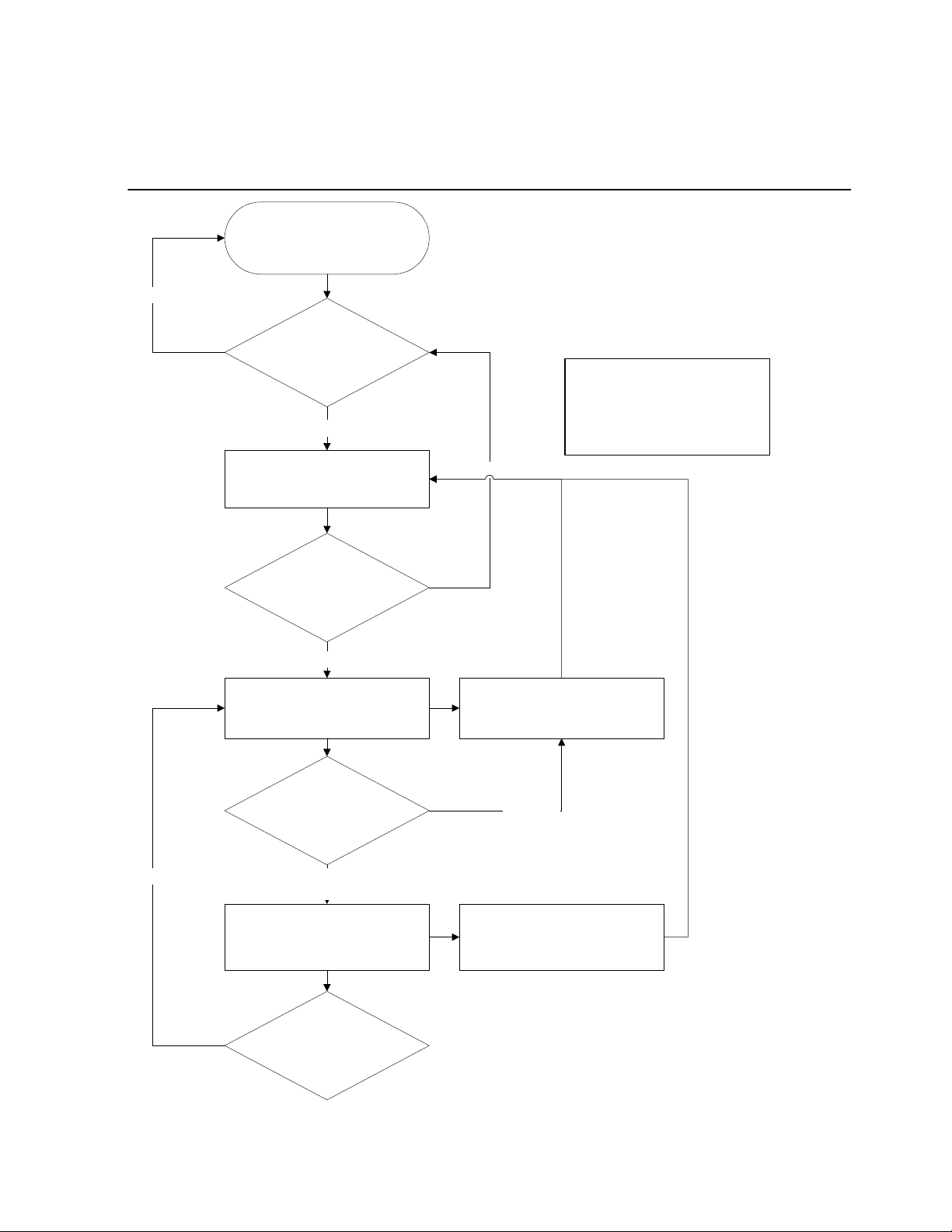
Network Customer Support Plan
Customer
Midas Network is functioning
properly?
No
Level One Contact is notified
Authorized Factory Service
Center
Resolved by Hardware repair
or Network Operations
troubleshooting?
No
Level Two Contact is notified
CEFD Customer Support
Hardware or Network
Operations issue?
*Note: If equipment was purchased
directly from Comtech EFData (not
through a Factory Authorized
Service Center), then CEFD
Customer Support will be the initial
point of contact.
Yes
CEFD Customer Support
provides HW support
Hardware
Hardware
Level Three Contact is notified
CEFD Network Test and Field
MIDAS 4.2 Basic Configuration, Rev. 1
Getting Started
iii
Network
Operations
Support
Hardware or Network
Operations issue?
CEFD Network Test and Field
Support
provides Network Operations
support
Page 6

See the Comtech EF Data website at www.comtechefdata.com for contact information
for a Factory Authorized Service Center.
Contact the Factory Authorized Service Center for product support or information on
upgrading or returning a product.
Contact the Comtech EF Data Customer Support Department for product support or
training, or information on upgrading or returning a product
A Customer Support representative may be reached at:
Comtech EF Data
Attention: Customer Support Department
2114 West 7th Street
Tempe, Arizona 85281 USA
480.333.2200 (Main Comtech EF Data Number)
480.333.4357 (Customer Support Desk)
480.333.2500 FAX
or, E-Mail can be sent to the Customer Support Department at:
service@comtechefdata.com
To return a Comtech EF Data product (in-warranty and out-of-warranty) for repair or
replacement:
1. Request a Return Material Authorization (RMA) number from the Comtech EF
Data Customer Support Department.
2. Be prepared to supply the Customer Support representative with the model
number, serial number, and a description of the problem.
3. To ensure that the product is not damaged during shipping, pack the product in
its original shipping carton/packaging.
4. Ship the product back to Comtech EF Data. (Shipping charges should be
prepaid.)
MIDAS 4.2 Basic Configuration, Rev. 1
Getting Started,
iv
Page 7

Contact the Comtech EF Data Network Test and Field Support
• System level Network Operations support
• Information on upgrading Network Operation software
• Reporting comments or suggestions concerning manuals
A Network Test and Field Support representative may be reached at:
Comtech EF Data
Attention: Network Test and Field Support
2114 West 7th Street
Tempe, Arizona 85281 USA
480.225.2200 (Main Comtech EF Data Number)
480.225.3693 (Network Test and Field Support)
480.333.2161 FAX
or, E-Mail can be sent to the Network Test and Field Support Department at:
mailto:midasfss@comtechefdata.com
Contact us via the web at www.comtechefdata.com
.
MIDAS 4.2 Basic Configuration, Rev. 1
Getting Started
v
Page 8

This page is intentionally left blank.
MIDAS 4.2 Basic Configuration, Rev. 1
Getting Started,
vi
Page 9

Table of Contents
CHAPTER 1. GETTING STARTED...........................................................................1–1
Introduction.............................................................................................................................................................1–1
MIDAS Overview.................................................................................................................................................1–1
MIDAS System Components............................................................................................................................1–3
Controller......................................................................................................................................................1–3
Local Client Workstation..............................................................................................................................1–3
Network Control Modem..............................................................................................................................1–3
LinkSync Modem.........................................................................................................................................1–3
Standard MIDAS System Features...................................................................................................................1–5
Options .........................................................................................................................................................1–5
Controller Server Redundancy ..........................................................................................................................1–5
Node ..................................................................................................................................................................1–7
Node Components........................................................................................................................................1–7
System Specifications ..............................................................................................................................................1–8
Using MIDAS...........................................................................................................................................................1–8
Starting the System ...............................................................................................................................................1–9
Logging On...........................................................................................................................................................1–9
Initial Configuration Startup ...............................................................................................................................1–10
Main Window......................................................................................................................................................1–11
Menu Bar.............................................................................................................................................................1–12
File Menu............................................................................................................................................................1–12
Reports Menu......................................................................................................................................................1–13
Configuration Menu............................................................................................................................................1–14
Maintenance Menu..............................................................................................................................................1–15
Window Menu..................................................................................................................................................... 1–15
Help Menu...........................................................................................................................................................1–15
Using Online Help...............................................................................................................................................1–16
About… Window................................................................................................................................................1–17
Logging Off.........................................................................................................................................................1–18
Exiting the System ..............................................................................................................................................1–19
Preparing for Software Setup...............................................................................................................................1–19
CHAPTER 2. SETUP AND OPERATION...................................................................2–1
Initial Setup Procedures..........................................................................................................................................2–1
System Settings.....................................................................................................................................................2–2
Satellite..................................................................................................................................................................2–3
Transponder...........................................................................................................................................................2–4
System Parameters................................................................................................................................................2–5
LinkSync ............................................................................................................................................................2–7
Power Setup......................................................................................................................................................2–8
AFC Setup ........................................................................................................................................................2–9
Data.....................................................................................................................................................................2–10
MIDAS 4.2 Basic Configuration, Rev. 1
Getting Started
vii
Page 10

Video...................................................................................................................................................................2–12
NMS (Controller)................................................................................................................................................2–14
Space Segment....................................................................................................................................................2–15
Bandwidth Pool Setup ....................................................................................................................................2–16
Major Bandwidth Pool Functions...................................................................................................................2–17
Adding Bandwidth Pools................................................................................................................................2–17
Private Pools...................................................................................................................................................2–18
Deleting Bandwidth Pools ..............................................................................................................................2–19
Space Segment Toolbar..................................................................................................................................2–20
Occupancy Graph Status Indicators....................................................................................................................2–22
Display Options...................................................................................................................................................2–23
Grid Properties................................................................................................................................................2–24
Legend Properties...........................................................................................................................................2–25
View Properties...............................................................................................................................................2–26
Control Channels.................................................................................................................................................2–26
Outbound Control Channel.............................................................................................................................2–26
Inbound Control Channel................................................................................................................................2–27
Control Channel Placement Selection........................................................................................................2–29
Outbound....................................................................................................................................................2–30
Inbound.......................................................................................................................................................2–31
Options .......................................................................................................................................................2–32
Aloha Parameters........................................................................................................................................2–33
Defining the Network Elements............................................................................................................................2–34
System Hierarchy................................................................................................................................................2–34
Site Types............................................................................................................................................................2–35
Sites..................................................................................................................................................................... 2–37
Nodes ..................................................................................................................................................................2–40
Channels..............................................................................................................................................................2–43
AUPC Settings for CDM-550, CDM-600, and CiM-550....................................................................................2–47
AUPC Settings for Other Comtech EF Data Modems........................................................................................2–48
Events Control Panel and Alarms .......................................................................................................................2–49
Security ...............................................................................................................................................................2–51
Assigning Connectivity..........................................................................................................................................2–53
Predefined Connections.......................................................................................................................................2–53
Communications Settings....................................................................................................................................2–58
Point to Multipoint Data Connections.................................................................................................................2–60
Point to Multipoint Data Details..........................................................................................................................2–63
Hunt Groups........................................................................................................................................................2–66
Available Channels....................................................................................................................................2–67
Assigned Channels .....................................................................................................................................2–68
Directory Numbers..............................................................................................................................................2–69
Video Conference................................................................................................................................................2–71
Adding a Video Conference............................................................................................................................2–71
Saving a Video Conference ............................................................................................................................2–73
CHAPTER 3. MIDAS REPORTS ............................................................................. 3–1
Report Options.........................................................................................................................................................3–2
Print Log Window...................................................................................................................................................3–3
Event Log .................................................................................................................................................................3–6
MIDAS 4.2 Basic Configuration, Rev. 1
Getting Started,
viii
Page 11

Occupancy Graph Report.......................................................................................................................................3–7
Completed Calls Report..........................................................................................................................................3–8
Active Calls Report................................................................................................................................................3–10
Control Channel Statistics Report.......................................................................................................................3–12
Control Channel Statistics Indicators..................................................................................................................3–12
Node Retry Statistics...........................................................................................................................................3–14
Resetting the Statistics ........................................................................................................................................3–15
Node-Channel Status Report................................................................................................................................3–16
Toolbar................................................................................................................................................................3–16
View....................................................................................................................................................................3–18
Summary Faults ..................................................................................................................................................3–19
Channel Faults.....................................................................................................................................................3–19
Node Faults .........................................................................................................................................................3–19
Site Faults............................................................................................................................................................3–19
CHAPTER 4. MAINTENANCE MENU........................................................................4–1
Controller Server.....................................................................................................................................................4–2
This Controller......................................................................................................................................................4–3
Other Controller....................................................................................................................................................4–3
Set Controller Mode..............................................................................................................................................4–4
Initiating Shutdown Mode................................................................................................................................4–4
Initiating Normal Mode ....................................................................................................................................4–5
Switch to Standby/Online Controller Server........................................................................................................4–5
Service Messages......................................................................................................................................................4–6
Set Time/Date...........................................................................................................................................................4–7
Export Billing Data..................................................................................................................................................4–7
Start the Backup....................................................................................................................................................4–8
Save As .................................................................................................................................................................4–8
Restoring a Backed Up Database.........................................................................................................................4–10
Restoring From Diskette .....................................................................................................................................4–11
Update Log Files....................................................................................................................................................4–12
APPENDIX A. FREQUENCY TRANSLATIONS.........................................................A–1
MIDAS 4.2 Basic Configuration, Rev. 1
Getting Started
ix
Page 12

About this Manual
This manual is written for the system operator using the MIDAS Bandwidth Management
System (BMS) software to configure and administer satellite communications network.
Metric Conversion
Metric conversion information is located on the inside back cover of this manual. This
information is provided to assist the operator in cross-referencing English to Metric
conversions.
Trademarks
Windows is a trademark of Microsoft Corporation.
Other product names mentioned in this manual may be trademarks or registered
trademarks of their respective companies, and are hereby acknowledged.
Reporting Comments or Suggestions
Comments and suggestions regarding the content and design of this manual will be
appreciated. To submit comments, please contact the Comtech EF Data Customer
Support Department.
MIDAS 4.2 Basic Configuration, Rev. 1
Getting Started,
x
Concerning this Manual
Page 13

Disclaimer
Comtech EF Data has reviewed this manual thoroughly in order that it will be an easy-touse guide to your equipment. All statements, technical information, and
recommendations in this manual and in any guides or related documents are believed
reliable, but the accuracy and completeness thereof are not guaranteed or warranted, and
they are not intended to be, nor should they be understood to be, representations or
warranties concerning the products described. Further, Comtech EF Data reserves the
right to make changes in the specifications of the products described in this manual at any
time without notice and without obligation to notify any person of such changes.
If you have any questions regarding your equipment or the information in this manual,
please contact the Comtech EF Data Customer Support Department.
MIDAS 4.2 Basic Configuration, Rev. 1
Getting Started
xi
Page 14

This page is intentionally left blank.
MIDAS 4.2 Basic Configuration, Rev. 1
Getting Started,
xii
Page 15
MULTIMEDIA INTEGRATED DIGITAL ACCESS SYSTEM
1
1
1
.
.
.
G
G
G
S
S
S
e
e
e
t
t
t
t
t
a
a
a
t
t
t
r
r
r
t
i
i
t
t
t
i
n
n
n
e
e
e
g
g
g
d
d
d
IInnttrroodduuccttiioonn
The Multimedia Integrated Digital Access System (MIDAS) is a sophisticated
power and transponder bandwidth management system for digital satellite
communication networks. MIDAS Controller software running in the server
provides the signaling and control elements for the network to provide
efficiently and cost effectively power transponder bandwidth and circuit
management on a demand basis.
The MIDAS software is distributed throughout the network with elements
residing within each MIDAS 1000 series control channel modem, providing
cost-effective scalability of the network. Portions of the MIDAS software also
reside in the network as the controller and in the operator workstation,
providing centralized control of power and transponder bandwidth, and
permitting enhanced features such as circuit prioritization and preemption.
MIDAS software provides a graphical user interface
(GUI) for bandwidth functions. Using MIDAS, the
operator configures, modifies, controls, and
monitors the elements in the satellite network. The
software provides:
• Graphical views of network statistics
• Input and maintenance of database
information
• Password-secured access to system functions
and data
MMIIDDAASS OOvveerrvviieeww
It is helpful to understand the basic description of a MIDAS satellite
communications network before proceeding with the explanation of the
MIDAS operating instructions.
MIDAS 4.2 Basic Configuration, Rev. 1
Getting Started 1–1
Page 16

MIDAS services include:
• Circuit Restoral
• Hunt Groups
• Priority Assignments and Preemption
• Bandwidth Pools
• Predefined Point-to-Point (P-P) and Point-to-Multipoint (PMP) Broadcast
Data and Video
• On-Demand PMP Symmetrical or Asymmetrical Return Channel
Assignments
The MIDAS Controller site hosts the combination of computers, printers,
software, and satellite modems responsible for managing the entire satellite
communications network. The site also could have one or more trafficcarrying nodes sharing the RF equipment with the controller. An on-site node
communicates with the controller over the satellite.
MIDAS 4.2 Basic Configuration, Rev. 1
1–2 Getting Started
Page 17

MIDAS System
Components
The MIDAS System consists of the following:
Call detail records can be
exported for offline billing.
LLooccaall CClliieenntt WWoorrkkssttaattiioonn
CCoonnttrroolllleerr
The Controller is a Pentium-based computer that also hosts the network
database. The control functions include:
• Network configuration maintenance (of both static and dynamic
information)
• Bandwidth and power management
• Circuit management
• Network monitoring and control
• Automatic Frequency Control (AFC)
The Controller Server also maintains an extensive log of all network events:
• Call detail records
• Alarms
• System events
The local client workstation is a Pentium desktop computer with the MIDAS
Client software (the GUI).
The local client workstation connects to the Controller Server through an
Ethernet LAN to provide the operator with an interface for configuring and
administering the network. Access to management functions is controlled
through passwords and access lists.
NNeettwwoorrkk CCoonnttrrooll MMooddeemm
LLiinnkkSSyynncc™™ MMooddeemm
The SNM-1001 Network Control Modem allows communication of call
control and network management messages with the remote nodes over the
control channels. The modem transmits on the outbound control channel to the
remote nodes and receives the incoming messages from the remote nodes on
the inbound control channel.
For detailed information on the network control modem, refer to the
SNM-1001 Network Control Modem Operation and Maintenance Manual.
The SNM-1002 LinkSync™ Modem monitors the outbound control channel
at the Controller Server site. The outbound control channel is used as the
frequency and power reference for LinkSync™ calculations.
MIDAS 4.2 Basic Configuration, Rev. 1
Getting Started 1–3
Page 18

LinkSync™ is a unique MIDAS feature that provides:
Automatic Frequency Control (AFC)
The AFC process compensates for earth station frequency drift due to
hardware aging and/or other factors, reducing the frequency uncertainty for
control and traffic channels. This compensation allows for faster call setup and
tighter carrier placement.
Uplink Power Control (UPC) at the Controller Server site
The UPC process dynamically adjusts the transmit power for the outbound
control channel, thereby allowing a constant power level to be received by the
downlink from the satellite. This adjustment makes it possible for the
outbound control channel to be used as a reference.
Circuit Disruption
MIDAS supports a family of single-channel traffic nodes using combined
control channel and traffic modems, such as the SNM-1010. These nodes
communicate on the control channel when no data circuit is active, and
reprogram themselves to become a traffic modem when the circuit is activated.
In the event that the network, or the network operator, needs to terminate or
preempt a circuit between two of these nodes, the LinkSync modem is used to
generate a carrier that forces the two nodes to lose carrier lock. This circuit
disruption causes the two nodes to reprogram themselves as control channel
modems and resume communication with the controller server.
Optional Circuit Power Management
Site-level call blocking ensures that a node does not transmit at a power level
beyond the capacity of the RF Amplifier. The system blocks circuit setup if
the total utilized power exceeds the power (less backoff) of the power
amplifier at that site, resulting in improved system stability.
For detailed information on the SNM-1002 LinkSync™ Modem, refer to the
SNM-1002 LinkSync™ Modem Operation and Maintenance Manual.
MIDAS 4.2 Basic Configuration, Rev. 1
1–4 Getting Started
Page 19

Standard MIDAS
System Features
Options
Standard features of the MIDAS System include:
• Network configuration and administration:
♦ Network monitoring and control
♦ Network data collection and processing
♦ Circuit setup, termination, and scheduling
♦ Call detail recording
♦ Printable logs and reports
• Bandwidth and power management:
♦ C-band or Ku-band operation
♦ Bandwidth and power allocation on demand
♦ Dedicated bandwidth pools
♦ Configurable channelization and carrier spacing
♦ LinkSync™ AFC and UPC
♦ Support 70/140 MHz and L-band modems
Controller Server
Redundancy
MIDAS System options include the following:
Redundancy
Redundant Network Control Modem
Redundant LinkSync™ Modem
LinkSync
Locally redundant Controller Server with automatic switch-over
Circuit Power Management
In an optional 1:1 redundant configuration, the backup Controller Server
monitors the active Controller Server and the RF chain.
MIDAS 4.2 Basic Configuration, Rev. 1
Getting Started 1–5
Page 20
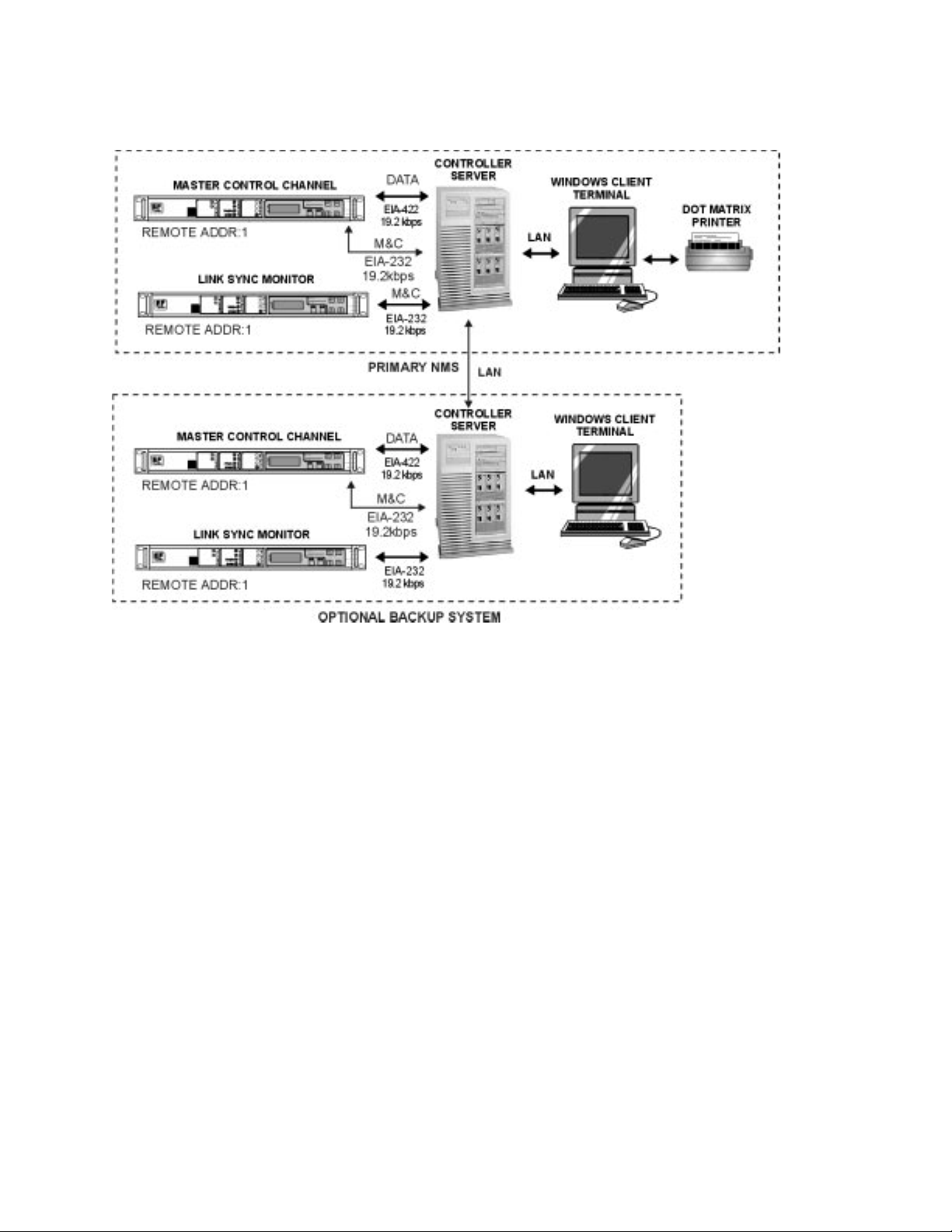
LAN
If a failure is detected in the active Controller Server or the RF chain, the
backup Controller Server assumes the active role. If required, the operator can
command a switch-over manually.
Active and backup Controller Server(s) synchronize the databases on the LAN
over a dedicated circuit.
Optional 1:1 redundancy for the Network Control Modem or the LinkSync™
Modem is provided via Comtech EF Data's SMS-301 Redundancy Switch.
Within 20 milliseconds of a detection of a fault in the online modem, the
SMS-301 switches to the backup modem.
The SMS-301 switch must be configured as remote address 1 running at
19.2 kbit/s. Modem A and Modem B must have remote addresses 2 and 3,
respectively. Those modems must be configured at 9600 bit/s.
For detailed information on the SMS-301 switch, refer to the SMS-301
Redundancy Switch Installation and Operation Manual.
MIDAS 4.2 Basic Configuration, Rev. 1
1–6 Getting Started
Page 21

Node
Node
Components
A MIDAS network node:
• Provides the interface for user traffic.
• Manages local resources in cooperation with the Controller Server.
A node can be located at a remote site, or at the controller server site. Multiple
nodes can be located at a remote site and share the RF equipment. As stated
previously, one or more nodes located at the controller site can share the RF
equipment.
A MIDAS node may consist of:
• SNM-1000 Node Control Modems, each controlling from 1 to 30 traffic
modems
• SNM-1010 Data/Control Modem, which serves as both the node control
modem and traffic modem
NNooddee CCoonnttrrooll MMooddeemm
DDaattaa//CCoonnttrrooll MMooddeemm
The SNM-1000 Node Control Modem performs as a dedicated node
controller. At a traffic node, it provides the interface to the controller server
and manages local resources under controller server control. It executes circuit
setup and termination, provides local M&C and diagnostics, and reports call
detail information to the controller server.
The SNM-1000 can manage up to 30 data modems.
For detailed information on the SNM-1000 Node Control Modem, refer to the
SNM-1000 Node Control Modem Operation and Maintenance Manual.
The SNM-1010 Data/Control Modem provides both control and traffic
functions, switching between the two modes as required. The unit is used at
sites that require single-channel data connectivity.
In control mode, the SNM-1010 provides the interface to the controller server.
The modulator (operating in burst mode) is tuned to the inbound control
channel; while the demodulator (operating in continuous mode) is tuned to the
outbound control channel.
To originate or receive a call, the SNM-1010 switches to traffic mode. While
carrying user traffic, the modem operates in continuous transmit and receive
mode. It supports data rates from 2.4 kbps to 5.0 Mbps.
MIDAS 4.2 Basic Configuration, Rev. 1
Getting Started 1–7
Page 22

For detailed information on the SNM-1010 Data/Control Modem, refer to the
SNM-1010 Data/Control Modem Operation and Maintenance Manual
EExxtteerrnnaall TTrraaffffiicc MMooddeemmss
SSyysstteemm
SSppeecciiffiiccaattiioonnss
Traffic requirements may be met by external traffic modems operating in
continuous mode.
Traffic modems supported by the SNM-1000 include:
Comtech EF Data SDM-100 Comtech EF Data SDM-8000
Comtech EF Data SDM-140
Comtech EF Data SDM-300/300A Comtech EF Data CDM-550
Comtech EF Data SDM-2020 Modulator
Comtech EF Data SDM-2020 Demodulator Comtech EF Data CDM-600
Comtech EF Data SDM-6000 Comtech EF Data CiM-550
Comtech EF Data SDM-9000
Comtech EF Data CDM-550T
For detailed information on the listed modems, refer to the applicable manuals.
Refer to the applicable manuals for specifications of the:
• System and Design Manual
UUssiinngg MMIIDDAASS
• MIDAS 4 Software Installation Guide
The MIDAS software consists of menus and windows designed for system
configuration, system administration, and reporting functions.
This section explains the general operating instructions for using the MIDAS
software, including
• Starting and exiting the Client software
• Working with the menus and windows
• Using the online help file
Subsequent chapters in this manual describe the configuration, administration,
and reporting functions of the software in detail.
MIDAS 4.2 Basic Configuration, Rev. 1
1–8 Getting Started
Page 23
SSttaarrttiinngg tthhee SSyysstteemm
p
Follow these steps to start the MIDAS software:
Power up the Controller Server and the local client workstation.
Double-Click the MIDAS CLIENT icon.
Progress messages are displayed as the software locates the server and loads
the database.
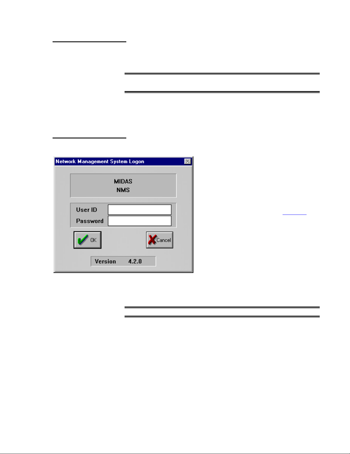
The Logon Window is displayed.
LLooggggiinngg OOnn
A valid User ID and Password must be entered to
gain access to the system.
The User ID and Password should be appropriate
to the authorized level of security. For setup
rocedures, use the Super User User ID and
Password. Refer to Security in Chapter 2
information about the Super User ID.
Follow these steps to log on to the system:
Type a valid User ID, Password, and click [OK].
for
MIDAS 4.2 Basic Configuration, Rev. 1
Getting Started 1–9
Page 24
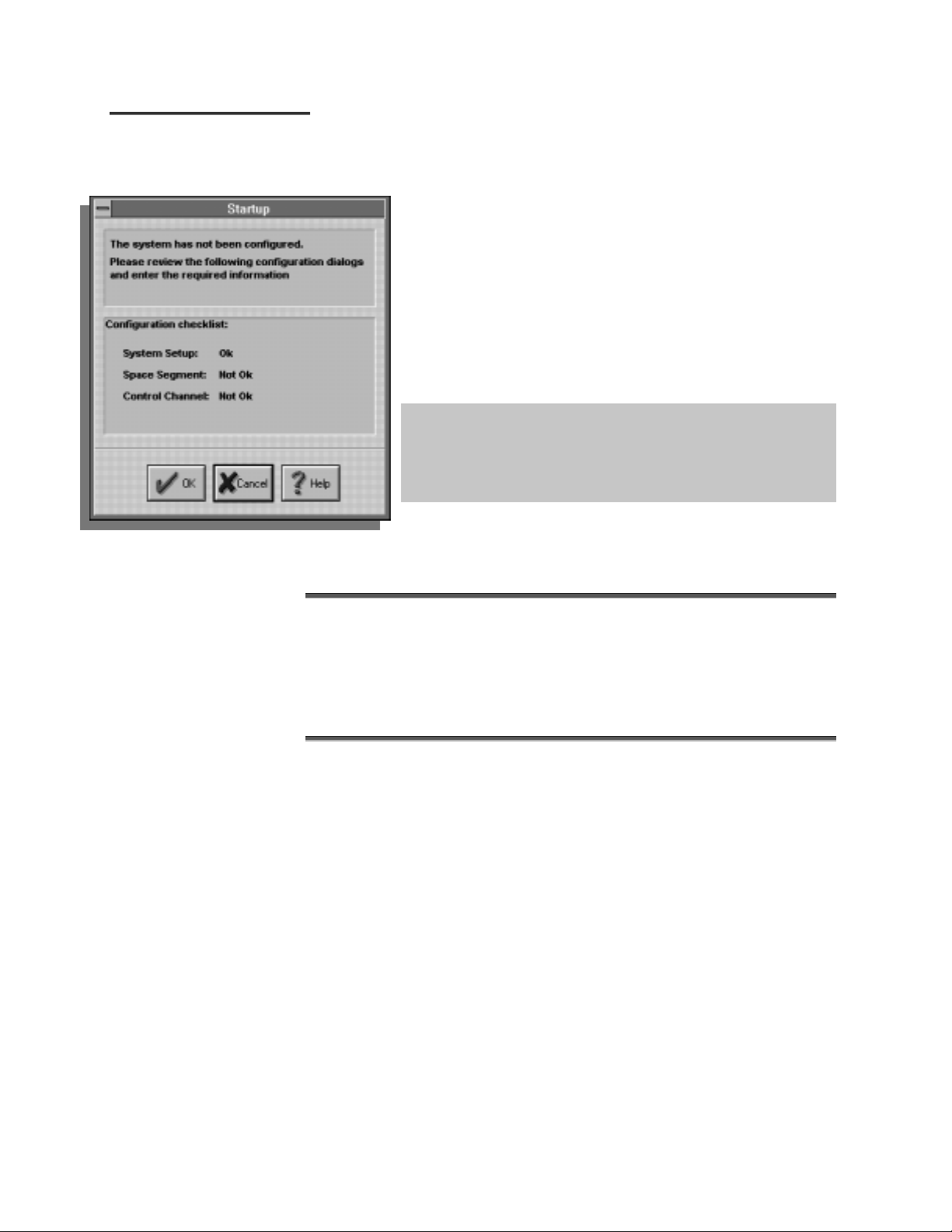
IInniittiiaall CCoonnffiigguurraattiioonn
SSttaarrttuupp
Refer to Chapter 2 for
detailed instructions on
configuring the system.
After logon, the Startup window is displayed in two instances:
after the first logon to a new system, and when all system
configuration information has not yet been entered into the
MIDAS database
The Startup window lists all sections of the system requiring
configuration data. Configuration status is indicated for each
section. Sections with complete configuration data are marked
as “Ok”. Sections with incomplete configuration data are
marked as “Not Ok”.
Because the system setup window contains default values that may not
apply to a particular setting, the user must verify the accuracy of system
setup values before initially configuring the system. It is critical that all
system setup values are understood and verified before proceeding
with system configuration.
The steps listed below describe the initial configuration scenario:
Click the [OK] button to configure the system. Each of the dialog boxes shown as “Not
Ok” on the checklist are automatically opened to allow the system to be configured.
Refer to Initial setup procedure in Section 2.
Verify the system setup. (Make changes if necessary.)
Configure the space segment.
Configure the control channel.
Once the system configuration has been completed, the Startup window will
no longer be displayed after logon.
MIDAS 4.2 Basic Configuration, Rev. 1
1–10 Getting Started
Page 25

MMaaiinn WWiinnddooww
Once valid Logon entries have been made, the Client’s main window is
displayed.
The main window contains the functional areas of MIDAS.
Note: After logon, a popup window will display “WAIT FOR CLIENT TO INITIATALIZE.”
This will take several seconds, dependent on the network database size.
Status Bar
The status bar (see illustration below) displays the current program status,
date, time, and alarm activity.
Displays NMS Controller State: Initializing, Running, or Exception.
Displays Controller Mode: Online or Standby.
Displays Controller Redundancy Configuration: Primary, Secondary, or No Backup
MIDAS 4.2 Basic Configuration, Rev. 1
Getting Started 1–11
Page 26
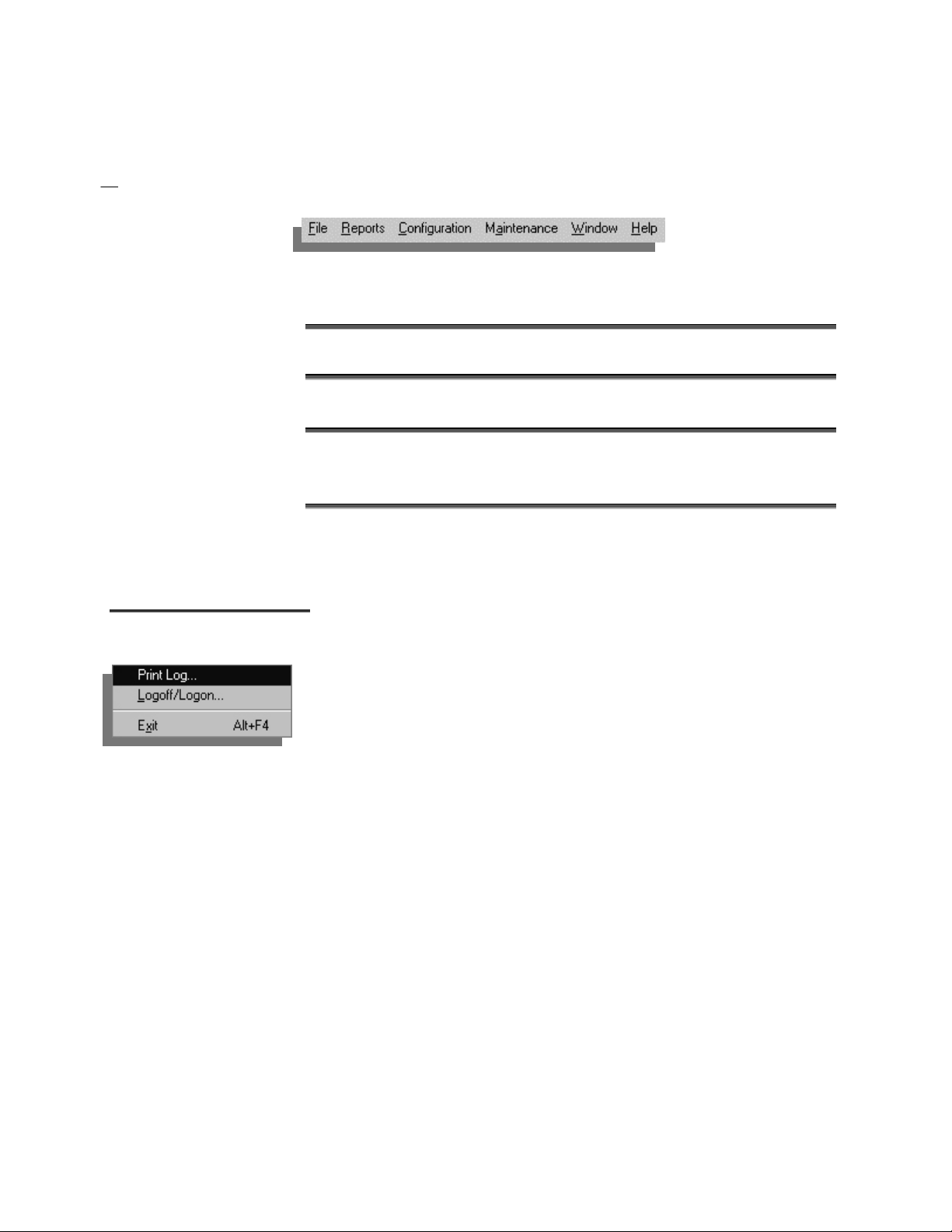
MMeennuu BBaarr
MIDAS Client is structured around a standard, Windows menu bar, which
provides access to several function-specific menus.
To use the menu bar:
Click on the desired menu title to open the menu.
Click on a menu option.
OR:
Type Alt+ the underlined letter of the desired menu title.
Use the Tab key to select a menu option.
Press the Enter key.
MIDAS menus are described in the following paragraphs.
FFiillee MMeennuu
The File menu contains these options:
PPrriinntt LLoogg
Select Print Log to set up the printer to print a real-time Event Log or
Completed Call Log. Customized reports are available as well.
LLooggooffff//LLooggoonn
Select Logoff/Logon to log on or off the MIDAS. Refer to the sections,
Logging On and Exiting the System, for a description of the Logon window.
EExxiitt
Select Exit to exit the MIDAS software.
MIDAS 4.2 Basic Configuration, Rev. 1
1–12 Getting Started
Page 27
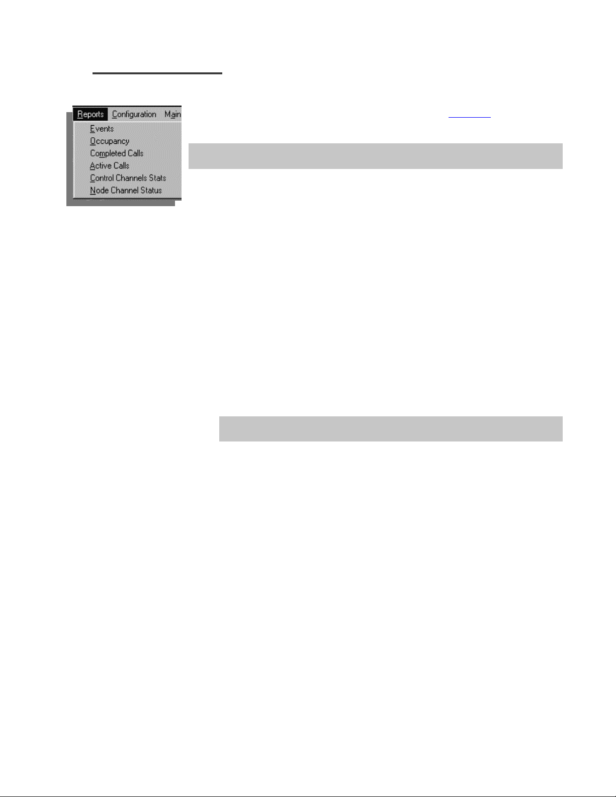
RReeppoorrttss MMeennuu
Select the Reports menu to view several reports online. See Chapter 3 for detailed
descriptions of these reports.
If a printer is connected to the operator workstation, a real-time Event Log or Completed Call
Log can be printed as well.
EEvveenntt LLoogg
The Event Log contains an account of system events that have occurred.
Events can be classified as normal events (start-up, shutdown, etc.), alarms,
warnings, etc.
OOccccuuppaannccyy RReeppoorrtt
CCoommpplleetteedd CCaallllss RReeppoorrtt
AAccttiivvee CCaallll
CCoonnttrrooll CChhaannnneell SSttaattiissttiiccss
The Occupancy Graph is a view-only, color-coded graphical representation of
the current status of the transponder bandwidth. It shows both free and
allocated bandwidth. The graph is updated automatically every 10 seconds.
The Completed Calls report lists all information about completed calls,
including the originating and destination terminals, start time and date, end
time and date, grade of service, etc.
The Controller Server maintains the call detail records, which can be exported in
comma-delimited format for offline billing.
The Active Call report shows all currently active calls. Information displayed
includes circuit and node identification, start time and date, circuit type and
status, and activity type.
The Control Channel Statistics report displays the parameters and current
statistics for a specified control channel. The default display shows “retries”
from all nodes associated with the control channel.
NNooddee--CChhaannnneell SSttaattuuss
The Node-Channel Status Report is a color-coded status report indicating the
current status of all sites, nodes, and channels within the network.
MIDAS 4.2 Basic Configuration, Rev. 1
Getting Started 1–13
Page 28
CCoonnffiigguurraattiioonn MMeennuu
Select the Configuration menu for access to the configuration maintenance
windows. See Chapter 2
• Security – used to create new system users, establish log-on passwords, and
assign individual access permission profiles
• Directory – used to maintain directory (phone) numbers for nodes and hunt
groups
• Sites – used to define site-specific configurations, including node and
channel definitions
• Site Types – used to create site type definitions and configure transmit
power for different combinations of sites
• Hunt Groups – used to set up logical “hunt” groups of one or more traffic
channels
• Predefined Connections – used to define the connection table and details, to
enable/disable connections, and to schedule reservation times
• Point to Multipoint - used to configure groups, channels, and broadcast
communications settings
• Video Conference – used to edit the video conference table and details, and
to save conference group information for future use
• Space Segment – used to view and administer the bandwidth utilization of
the transponder
• Control Channels – used to configure control channel parameters and set
polling sub-system options
• Events Control Panel – used to view all system events, and to set up the
events and alarm options
• System Setup – used to establish general system operating parameters for
the satellite, transponder, and LinkSync, and to store settings for Data,
Video, Modem, NMS operation, and slots.
for detailed descriptions of these items.
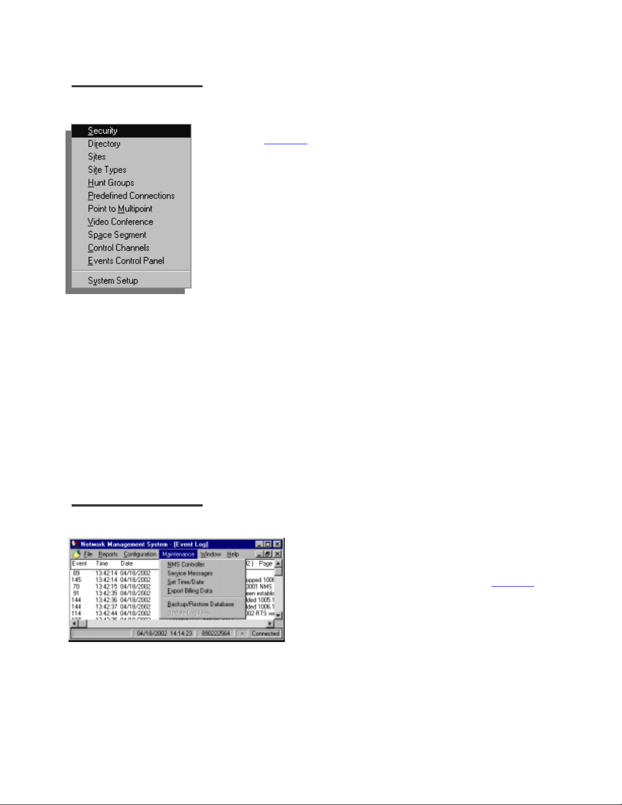
MMaaiinntteennaannccee MMeennuu
MIDAS 4.2 Basic Configuration, Rev. 1
1–14 Getting Started
Select the Maintenance menu for access to the following
system maintenance functions:
Maintenance Menu items are explained in Chapter 4
• NMS Controller (Controller Server)
• Service Messages
• Set Time/Date
• Backup Database
• Backup/Restore Database
.
Page 29
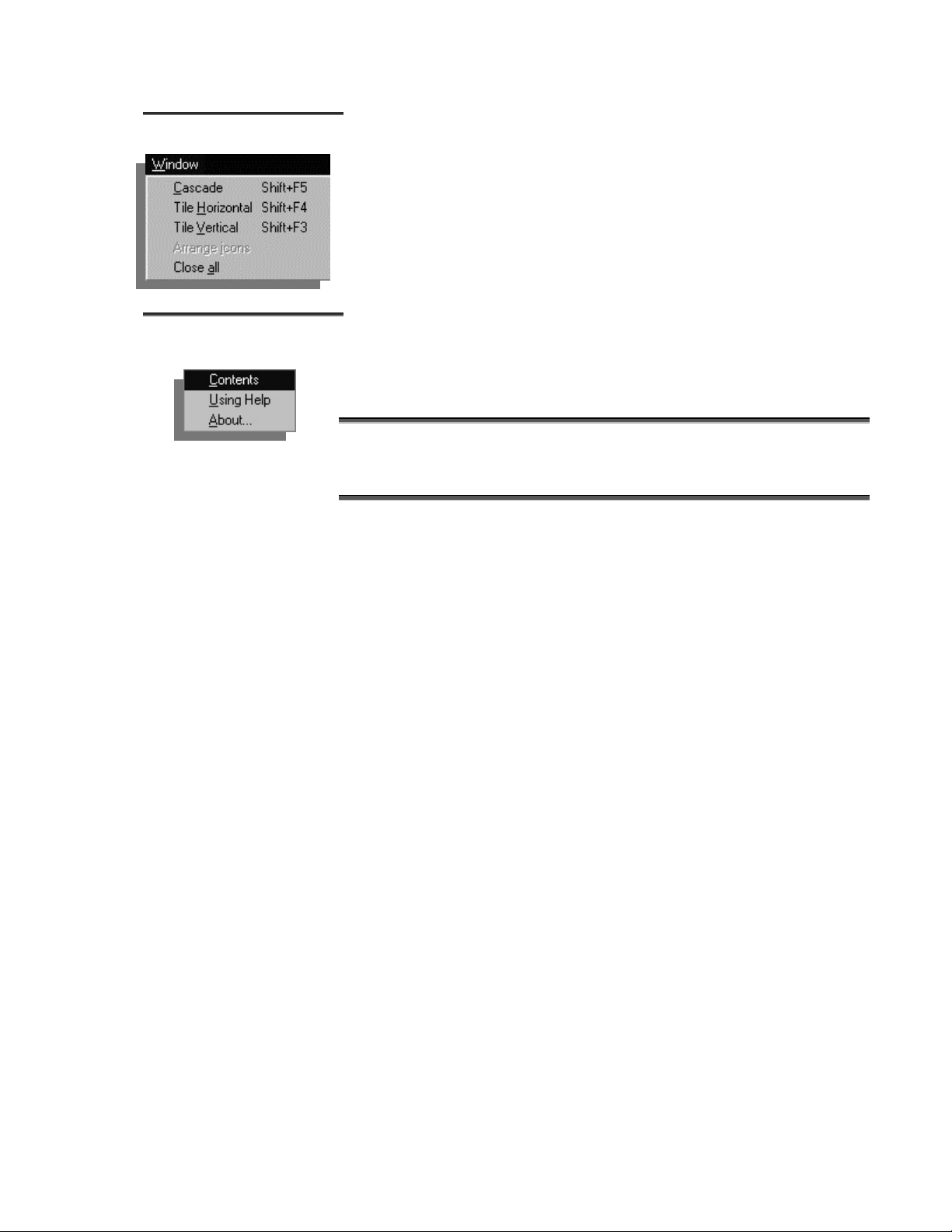
WWiinnddooww MMeennuu
The options on the Window menu are used for window manipulation.
HHeellpp MMeennuu
Access to the online help reference system is available by selecting the Help
menu on the menu bar.
Select Contents to display the online help Table Of Contents.
Select Using Help to display instructions for navigating within the online help reference.
Select About… to display the About MIDAS window.
MIDAS 4.2 Basic Configuration, Rev. 1
Getting Started 1–15
Page 30
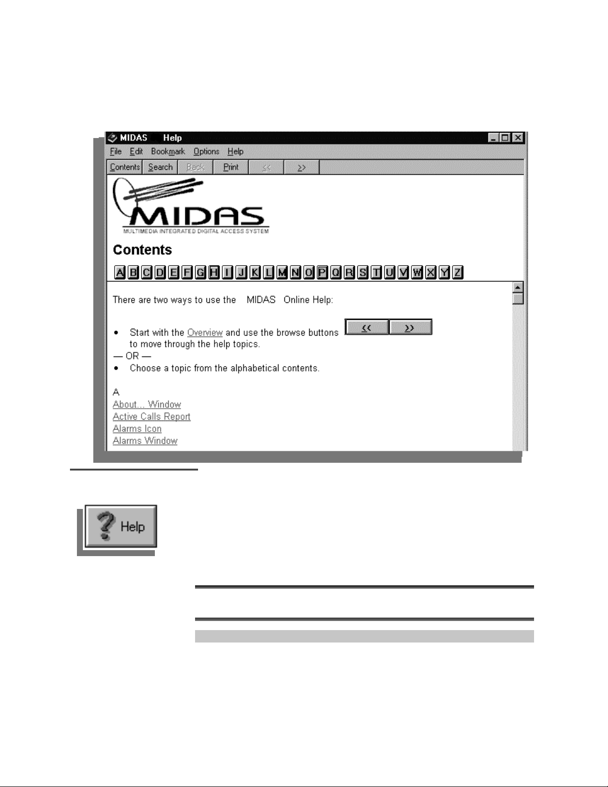
The online help Table of Contents also contains instructions for moving
through the help system.
UUssiinngg OOnnlliinnee HHeellpp
MIDAS 4.2 Basic Configuration, Rev. 1
1–16 Getting Started
A complete and detailed help reference system is provided with the MIDAS
software.
Window-specific help is available on most windows. To use this contextsensitive help:
Click on the [HELP] button where it appears on any MIDAS window .
If no [HELP] button is present, press [F1] to display help.
Use the Help menu (see page 1–15) to access the online help reference as well.
Page 31

AAbboouutt…… WWiinnddooww
The About... window displays information such as serial number, software
version, and copyright information. Options installed are also listed on the
About… window.
Click [OK] to exit the About... window.
MIDAS 4.2 Basic Configuration, Rev. 1
Getting Started 1–17
Page 32

LLooggggiinngg OOffff
TToo lloogg ooffff MMIIDDAASS::
Select File, Logoff/Logon….
Click OK on the Network Management System Logon window .
Another user may now log on.
Clicking the Cancel button exits the system.
MIDAS 4.2 Basic Configuration, Rev. 1
1–18 Getting Started
Page 33

EExxiittiinngg tthhee SSyysstteemm
TToo eexxiitt MMIIDDAASS::
PPrreeppaarriinngg ffoorr
SSooffttwwaarree SSeettuupp
Select File, Exit.
Or
Click the [X] button at the top right corner of the window.
Note: Manufacturer recommends performing all of the following steps before
connecting MIDAS controlled modems to external RF equipment.
Network configuration information must be collected, verified, and recorded
before proceeding with the software setup described in Chapter 2.
MIDAS windows will prompt for network parameters such as:
• Circuit connectivity
• Satellite/Transponder parameters and descriptions
• Site parameters and descriptions
• Site transmit power parameters
• Node parameters and descriptions
• Traffic channel parameters and descriptions
• System user data (security)
• Control channel parameters and descriptions
• Directory numbers and hunt group members
Detailed descriptions of the information required for each of these categories
are provided in Chapter 2
the applicable configuration information for your network before performing
the initial setup.
and Appendix A. After reading Chapter 2, document
MIDAS 4.2 Basic Configuration, Rev. 1
Getting Started 1–19
Page 34

This page is intentionally left blank.
MIDAS 4.2 Basic Configuration, Rev. 1
1–20 Getting Started
Page 35

MULTIMEDIA INTEGRATED DIGITAL ACCESS SYSTEM
2
2
2
.
.
.
S
S
S
O
O
O
e
e
e
p
p
p
t
t
t
u
u
u
e
e
e
r
r
r
p
p
p
a
a
a
a
a
a
t
t
t
i
i
i
n
n
n
o
o
o
d
d
d
n
n
n
IInniittiiaall SSeettuupp
PPrroocceedduurreess
After collecting the applicable network information described in this chapter,
complete the initial MIDAS software setup. In general, software setup consists
of the following sections:
• System Settings (System Setup window)
♦ System Setup (System Setup window)
♦ Space Segment (Space Segment wi ndow)
♦ Control Channel (Control Channel window)
• Defining the Network Elements
♦ Site Types
♦ Sites
♦ Nodes
♦ Channels
• Assigning Connectivity
♦ Predefined Connections
♦ Connection
♦ Point to Multipoint Data Connections
♦ Hunt Groups
♦ Directory Numbers
♦ Video Confe re n ce
MIDAS 4.2 Basic Configuration, Rev. 1
Setup and Operation 2–1
Page 36

SSyysstteemm SSeettttiinnggss
Use the System Setup window to configure the various system-specific
settings.
Because the system setup window contains default values that may not
apply to a particular setting, verify the accuracy of system setup values
before initially configuring the system. It is critical that all system setup
values are entered accurately before proceeding with system
configuration.
From the main window, click Configuration then System Setup to access the System
Setup window.
Enter the System Se tup in fo rma tion an d mak e the de sired selecti ons in the Sy stem
Setup window, which consists of four majo r sections (Satel lite, Tra nspo nder, Sy stem
Parameters, and LinkSy nc), and five additional setup bu tton s (Da ta, Vi deo, Mode m,
and Slots).
MIDAS 4.2 Basic Configuration, Rev. 1
2–2 Setup and Operation
Page 37

SSaatteelllliittee
Note: The settings for the System Setup are critical for the MIDAS System
to operate. It is necessary to configure the parameters correctly and in the
following order. For additional information on Satellite Frequency
Translations, refer to Appendix A.
Step Nomenclature Description
1 Satellite Name Enter the Satellite Name.
2 Frequency Band Select the frequency band, C or Ku.
For C-band, high-side injection is the default. For Ku-band, low-side injection is the default.
High-side injection is calculated as follows:
LBand = Uplink Factor – Transponder TX Center
- or -
L-band = Downlink Factor – Transponder RX Center
Low-side injection is calculated as follows:
L-band = Transponder TX Center – Uplink Factor
- or -
L-band = Transponder RX Center – Downlink Factor
3 High-Side Injection Click the checkbox to select high-side injection, leave blank for low-side injection.
Default : For C-Band - High-Side Injection
For Ku-Band – Low-Side Injection
4 Translation Factor Enter the value (in GHz) for the Translation Factor to be used for low- or high-side injection calculations.
Translation Factor = Transponder TX Center – Transponder RX Center
Default is 2.225 GHz for C-Band and 2.3 GHz for Ku-Band.
5 Downlink Factor Enter the value (in GHz) for the Downlink Factor to be used for low- or high-side injection calculations.
Downlink Factor = LO (Low Oscillator Frequency) of the LNB (Low Noise Block Converter)
Typical C-Band Lo’s are: 5.15 GHz and 5.76 GHz
Typical Ku-Band LO’s are: 10.75 GHz, 10.0 GHz, and 11.3 GHz.
6 Uplink Factor No entry is required, the MIDAS System will calculate this based upon the transponder frequency setting.
MIDAS 4.2 Basic Configuration, Rev. 1
Setup and Operation 2–3
Page 38

TTrraannssppoonnddeerr
Step Nomenclature Description
1 Transponder Name Enter the transponder name.
2 Transponder Size Enter 36, 54, or 72 MHz.
3
By entering either the TX or RX Center frequency, MIDAS will calculate the
other frequency based upon the Satellite Translation frequency. MIDAS also
will calculate the L-Band frequency based upon the difference between the
Satellite Downlink Factor (LNB LO) and the Transponder RX Center
frequency. Valid L-Band range is: 950 to 1750 MHz.
Note: When operating a MIDAS System that supports any L-Band
modems, it is critical to have the correct settings. Refer to Appendix A for
additional information on Satellite Frequency Translation.
Note: This is not critical for MIDAS operation. It
only affects the viewable amount in the Space
Segment window.
TX Center Enter the RF TX (transmit) center frequency of the
transponder.
Valid range is:
C-band = 5.85 to 8 GHz
Ku-band = 12 to 14.5 GHz
RX Center
Enter the RF RX (receive) center frequency of the
transponder.
Valid range is:
C-Band = 3 to 5 GHz
Ku-Band = 10 to 12.75 GHz
MIDAS 4.2 Basic Configuration, Rev. 1
2–4 Setup and Operation
Page 39

SSyysstteemm PPaarraammeetteerrss
This section of the System Setup window allows selection of the following
System Parameters:
AAllllooccaattiioonn FFaaccttoorr
SStteepp SSiizzee
IIFF CCeenntteerr
This is a factor, or multiplier, used as a carrier spacing placed between carrier
assignments to avoid interference (roll-offs, skirts). A typical Allocation Factor
is 1.4. Using a larger number will provide a larger spacing, but will also take
up valuable transponder space.
This is the smallest unit of bandwidth that will be displayed and allocated on
the Space Segment. Range: 2.5 to 25.0 kHz.
Note: This will define the frequency resolution of the MIDAS System.
This is the IF Center frequency of the transponder, depending on the specific
hardware involved, 70 or 140 MHz.
Caution! The Step Size and IF Center values should be changed only
when configuring the system for the first time, or if a substantial system
reconfiguration is required. Ch angin g these values requires a system reset
(reboot), and will cause the loss of key bandwidth related information.
Additionally, all Active Calls will be deleted.
After the system is restarted, the Space Segment and Control Channels
must be reconfigured.
KKeeeepp LLooggss ffoorr
LLoocckk TTiimmee
EEnnaabbllee PPoowweerr MMaannaaggeemmeenntt
This parameter sets the numb er of da ys that l ogs will be ke p t be f ore th e y are
deleted from the system.
This sets the amount of time, in seconds, that a node will wait after a circuit is
successfully established before checking the traffic modems for loss of carrier.
It is only after this "stabilization" period that the node sends a terminate
message back to the Controller Server if the circuit failed due to carrier loss.
When this checkbox is selected, the MIDAS controller can perform power
calculations during call setup, as defined on the Power Setup window.
MIDAS 4.2 Basic Configuration, Rev. 1
Setup and Operation 2–5
Page 40

EEnnaabbllee AAFFCC
When this checkbox is selected, the MIDAS controller can perform Automatic
Frequency Contr ol (A FC) as de f i ned on the AF C Se tu p w in dow .
EEnnaabbllee RReedduunnddaanntt NNMMSS
This checkbox enables or disables the Redundant NMS (Controller) function,
which allows configuration of redundant NMS servers as Primary and
Secondary units. Enabling this function automatically displays the Network
Control Modem window.
The operator can also click the Setup button
on the System Setup window at any time to
display the Redundant NMS window, and
configure the following settings.
Configure as: – this refers to the NMS status
(Primary, Secondary, or No Backup).
Listen for Outbound for How Long? – this
refers to the length of time the Primary NMS
will listen for the Outbound Control Channel
during startup in order to avoid interfering
with other si gn a ls .
For a Secondary NMS, this is the period of
delay before the unit comes online or takes
over the operation of the network.
Example: If the Primary NMS fails and is then backed up by the Secondary
NMS, the failed NMS will automatically be restored to Primary status as soon
as it is operational again.
MIDAS 4.2 Basic Configuration, Rev. 1
2–6 Setup and Operation
Auto restore Primary – this enables or
disables the function which will automatically
restore the Primary NMS. Auto restoration
occurs in less than 5 minutes.
Page 41

LLiinnkkSSyynnc
c
LinkSync™ is a unique MIDAS feature providing:
• Automatic Frequency Control (AFC)
• Uplink Power Control (UPC) at Controller Server site
• Circuit Power Management (Optional)
♦ Site-level call blocking based on HPA power
The AFC process compensates for earth station frequency drift, thereby
reducing the frequency uncertainty for control and traffic channels to within
± 500 Hz of the nominal. This allows for faster call setup, tighter placement of
carriers, and reduced maintenance for RF equipment.
The UPC process dynamically adjusts the uplink transmit power level of the
outbound control channel, thereby allowing it to be downlinked at a constant
power level from the satellite. This function makes it possible for the outbound
control channel to be used as a network wide reference.
Site level call blocking ensures that a node does not transmit at a power level
beyond the High Power Amplifier (HPA) capacity. The system blocks a circuit
from being set up if the HPA will exceed the rated power (less backoff), thus
improving system stability.
The LinkSync section of the System Setup window consists of two buttons
and two checkboxes that allow the operator to enable/disable and configure the
Power and Automatic Frequency Control settings.
MIDAS 4.2 Basic Configuration, Rev. 1
Setup and Operation 2–7
Page 42

Power Setup
Click the Power Setup button to display the Power Setup window, which allows the
operator to configure the following power control settings when LinkSync is enabled:
UPC Time Interval – this setting
determines how frequently the system
will calculate and adjust the power levels
of the outbound control channel. This
time interval will vary depending on the
specific equipment involved, but will
generally be more frequent for Ku-band,
due to rain fade, for example.
UPC Threshold – this is the threshold level at which the Uplink Power
Control feature will be enabled, and the level adjusted. In other words, the
minimum difference between the current and calculated control channel power
levels before the power level will be adjusted (Range .1 to 1.0 dB).
MIDAS 4.2 Basic Configuration, Rev. 1
2–8 Setup and Operation
Page 43

AFC Setup
Click the AFC Setup button to display the AFC Settings window.
The AFC Settings window allows the
operator to configure the following
Automatic Frequency Control settings:
AFC Start Delay – this is the amount of
time that the Automatic Frequency Control
function will be delayed before starting
periodic frequency measurement and
adjustment functions. This delay is
designed to allow the oscillator crystals to
achieve operating temperature and
stabilize, therefore providing better
frequency accuracy. It also allows time for
nodes to execute their startup procedures.
NMS (Controller) Freq. Check Interval
– this setting determines how often the
NMS (Controller) will take readings of
and perform adjustments to the Inbound
Control Channel frequency.
Node Alignment
Start Time of day– this is the time of day the operator wants the Node
Alignment function to occur. The best time to perform this function is during
periods of low system traffic, to minimize slowing of the network.
Nodes per day – this is the number of nodes to be aligned per day. The system
will perform node alignment in sequential order, continuing each day from
wherever it stopped the previous day. The actual number of nodes aligned is
Nodes per day, or the total number of enabled nodes, whichever is less.
Time between – this setting determines the amount of time in between node
alignments, according to the specific needs of the operator.
Alarm threshold – this is the threshold frequency level at which an event or
alarm (as specified in the events control panel) will occur as a result of
excessive transmit frequency offset at the node, as measured by the NMS
during a periodic alignment.
Acquisition Timeout – this is the maximum amount of time that the NMS will
wait for a response from a node during node alignment, before bypassing
frequency alignment of that node.
MIDAS 4.2 Basic Configuration, Rev. 1
Setup and Operation 2–9
Page 44

DDaattaa
Click the Data button to display the Data Settings window.
The Data Settings window allows the
operator to select the following Data
settings:
SSNNMM
EEnnccooddiinngg
This is the default power level for the Satellite Network Modem, in dBm.
This drop-down box allows the operator to select the Encoding type, Viterbi,
Sequential, Turbo, TCM, TCM with Reed-Solomon, Viterbi with ReedSolomon, or Sequential with Reed-Solomon.
MIDAS 4.2 Basic Configuration, Rev. 1
2–10 Setup and Operation
Note: The power level setting must be based upon the link budget
with a 10 kbps, QPSK, R=1/2 carrier.
The MIDAS System will give a recommended power level for any
data call based upon the data rate, modulation, and FEC of that
call. The operator can use the recommended power level or selects
Page 45

RRiinngg TTiimmeeoouutt
This drop-down box allows the operator to select the amount of time, in
seconds, that the call will ring waiting for call setup before disconnecting.
MMaaxx CCaallll DDuurraattiioonn
UUnnlliimmiitteedd
DDoopppplleerr BBuuffffeerr
This is the maximum call length allowed, in seconds, and will only apply if the
Unlimited checkbox is not selected. This will vary according to the operator’s
discretion, and/or system bandwidth limitations.
When selected, this checkbox allows calls of unlimited time duration. When it
is not selected, the amount of time specified in the Max Call Duration field will
apply.
This allows the operator to enter the Doppler Buffer size, in bits, to
compensate for satellite movement.
• The depth of the receive buffer will depend upon four parameters:
• Doppler shift caused by satellite movement
• Stability of each clock (plesiochronous/Doppler operation only)
• Frame/Multiframe length of multiplexed data format
• Allowable time between clock slips
Doppler shift results from the movement of the satellite in space over a
period of one day in relation to the earth station. Doppler shift should not
result in a clock slip as the buffer will constantly fill and empty due to the
cyclic nature of the satellite motion .
DDVVBB FFrraammee
Depending on the location of the earth station relative to the satellite, the
variation in propagation delay will typically be 1.15 ms (up to satellite and
back down). So, 2 ms will be sufficient for most commercial satellites.
Bits to Seconds:
1/DATA RATE * BITS = SECONDS
Seconds to Bits:
DATA RATE * SECONDS = BITS
When an SDM-2020 modulator/demodulator is in use, this drop-down box
allows the operator to select from three types of DVB frame: 187 (none), 188,
or 204.
MIDAS 4.2 Basic Configuration, Rev. 1
Setup and Operation 2–11
Page 46

VViiddeeoo
EEnnccooddiinngg
Click the Video button to display the Video Settings window.
The Video Settings window allows the operator
to select the following video settings for the video
signals:
This drop-down box allows the operator to select the Encoding type, Viterbi,
Sequential, Turbo, TCM, TCM with Reed-Solomon, Viterbi with ReedSolomon, or Sequential with Reed-Solomon.
Note: SDM-300 Satellite Modem does not incorporated Turbo
capabilities.
DDeeffaauulltt PPoowweerr
This is the default TX power level of the traffic modem for the Video call, in
dBm (Range: -30 to -5 dBm). This power applies to the selected grade of
service. If a videoconference is i nitia te d at a di ffe rent da ta rate , the power is
scaled accordingly.
Note: The power level setting must be based upon the link budget with a 10
kbps, QPSK, R=1/2 carrier.
The MIDAS System will give a recommended power level for any video call
based upon the data rate, modulation, and FEC of that call. The operator
can use the recommended power level or select the appropriate power level.
MIDAS 4.2 Basic Configuration, Rev. 1
2–12 Setup and Operation
Page 47

GGrraaddee ooff SSeerrvviiccee
RRiinngg TTiimmeeoouutt
This drop-down box allows the operator to select the Grade of Service for their
Video call. Thi s wi ll d e pend on t he des i red cost versus quality requirements.
The GOS choices f o r Video include:
• 128 1/2, 128 3/4 • 256 1/2, 256 3/4
• 384 1/2, 384 3/4 • 512 1/2, 512 3/4
• 768 1/2, 768 3/4
This drop-down box allows the operator to select the amount of time, in
seconds, that the system will ring waiting for call setup before disconnecting.
MMaaxx CCaallll DDuurraattiioonn
UUnnlliimmiitteedd
DDoopppplleerr BBuuffffeerr
This is the maximum call length allowed, in seconds, and will only apply if the
Unlimited checkbox is not selected. This will vary according to the operator’s
discretion, and/or system bandwidth limitations.
When selected, this checkbox allows calls of unlimited time duration. When it
is not selected, the amount of time specified in the Max Call Duration field will
apply.
This allows the operator to enter the Doppler Buffer size, in bits, to
compensate for satellite movement.
• The depth of the receive buffer will depend upon four parameters:
• Doppler shift caused by satellite movement
• Stability of each clock (plesiochronous/Doppler operation only)
• Frame/Multiframe length of multiplexed data format
• Allowable time between clock slips
Doppler shift results from the movement of the satellite in space over a
period of one day in relation to the earth station. Doppler shift should not
result in a clock slip as the buffer will constantly fill and empty due to the
cyclic nature of the satellite motion .
Depending on the location of the earth station relative to the satellite, the
variation in propagation delay will typically be 1.15 ms (up to satellite and
back down). So, 2 ms will be sufficient for most commercial satellites.
Bits to Seconds: 1/DATA RATE * BITS = SECONDS
Seconds to Bits: DATA RATE * SECONDS = BITS
MIDAS 4.2 Basic Configuration, Rev. 1
Setup and Operation 2–13
Page 48

NNMMSS ((CCoonnttrroolllleerr))
Click the NMS button to display the Network Control Modem window.
Note: The Control Channel settings will need to be entered before
configuring Control Modem Redundancy (Default is No Redundancy for
Network Control Modem and LinkSync Modem. Therefore, the
MIDAS System shall have the transponder, space segment, and control
channel frequencies entered without redundant control or LinkSync
modems.
The Network Control Modem
window allows the operator to select
whether the Network Control Modem
and LinkSync modem will be set up
with redundant backup modems in
their particular system configuration.
NNeettwwoorrkk CCoonnttrrooll MMooddeemm
LLiinnkkSSyynnc
This drop-down box allows the operator to select either Redundant or No
Redundant backup for the Network Control Modem. Redundant selects an
SMS-301 switch, to provide modem redundancy. No Redundant selects a
control modem, which is not connected via a switch and therefore does not
provide redundant backup.
c
This drop-down box allows the operator to select either Redundant or No
Redundant backup for the LinkSync modem. Redundant selects an SMS-301
switch, to provide modem redundancy. No Redundant selects a control
modem, which is not connected via a switch and therefore does not provide
redundant backup.
MIDAS 4.2 Basic Configuration, Rev. 1
2–14 Setup and Operation
Page 49

SSppaaccee SSeeggmmeenntt
The Space Segment window allows the operator to view and change the
bandwidth utilization of the transponder.
From the main window, click Configuration then Space Segment display the Space
Segment window.
The Occupancy Graph Report (refer to Chapter 3
Segment, but only allows viewing. The allocated Space Segment consists of
one or more fractions of transponder bandwidth. These fractions do not have to
be contiguous. The bandwidth allocation granularity (step size) is user
selectable from 2.5 to 25.0 kHz, in 2.5 kHz increments.
) looks similar to the Space
MIDAS 4.2 Basic Configuration, Rev. 1
Setup and Operation 2–15
Page 50

Bandwidth Pool
Setup
The display consists of the following major functional areas:
• Space Segment Graph – shows the entire bandwidth of the transponder.
♦ Each bloc k on th e gr ap h repr es e nts one channel or allocation unit.
♦ Row and column headers label the position of the graph display within
the transponder range.
♦ Labels indicate either channel numbers or IF values, depending on the
selection of the Show Frequency option.
♦ Bandwidth can be allocated from either public or private pools. The
public pool will be allocated on a “first come, first served” basis, but
the private pools will be dedicated, guaranteed bandwidth for
customers who require it.
♦ Each block in the graph is color-coded to represent allocated
bandwidth, free bandwidth, control channels, or active calls.
♦ In ‘Display by Circuit Type’ mode, the graph is color-coded to
represent the Data, and Video circuits.
Allocated bandwidth belongs to a pool. By default, bandwidth belongs to the
public pool, but private pools can be created using the Add Bandwidth
window, in which the user can specify the pool type and parameters.
The Space Segment’s bandwidth allocation method is based on the use of
Bandwidth Pools. Pools are segments of bandwidth that are designated as one
of the following:
• Private pools – this pool type is used for customers that require full-time
dedicated bandwidth. Private pools are a means of having guaranteed
available bandwidth at any time. The private pool’s bandwidth is
exclusively allocated to a single customer, and will not be shared or
reallocated, even though it may be unused at certain times. In addition to
the private pool, customers can choose to have an Overflow percentage
added to their account, which allows a certain amount of excess bandwidth
to be borrowed (when available) from the Free pool, if their bandwidth
needs exceed their private pool size.
• Public pools – this pool type is for general use, and is allocated to
customers on a simple “first come, first served” basis. Customers that do
not need full-time dedicated bandwidth may use public pools.
• Free pool – this is the unused, or unallocated, portion of available
bandwidth on the transponder. The size of the free pool is constantly
changing as bandwidth is allocated from and returned to the free pool.
MIDAS 4.2 Basic Configuration, Rev. 1
2–16 Setup and Operation
Page 51

Major Bandwidth
Pool Functions
Adding Bandwidth
Pools
The major functions within the Space Segment include Adding, Deleting,
Locking and Unlocking Bandwidth Pools.
The Add Bandwidth window allows the operator to add new bandwidth pools
on the Space Segment grid.
To add bandwidth from the Free pool to the Public pool (as pictured below) or a Private
pool, double-click on the desired Free bandwidth area within the Space Segment grid,
or click on the Free bandwidth, then click
Bandwidth window.
To add bandwidth from the Public pool to a Private pool, click the desired Public pool
area, then click
on the Toolbar. This displays the Add Bandwidth w indow .
on the Toolbar. This displays the Add
Click the “To:” drop-down box and select from list which pool the bandw idth w ill be
added to (Public, or the specific customer name fo r Private).
Select the appropriate radio button for the desired measurement unit to view the Range
(RF RX, RF TX, IF, LBand or Channel ).
Enter the desired bandwidth range values (Start and End) of the poo l to be add ed, the n
click OK.
MIDAS 4.2 Basic Configuration, Rev. 1
Setup and Operation 2–17
Page 52

Private Pools
Private bandwidth pools provide dedicated bandwidth for customers requiring
full-time access, as opposed to the “first come, first served” method used with
the bandwidth in the Public pool. If Private is selected, the Allow Public
Overflow Usage function can be en abled. If Allow Public Overflow Us a ge is
enabled, the pe rc ent a ge of ov e rfl o w ba n dwi dt h all owe d f or t he pa rt icul a r
account/customer (if any) can be entered. Should overflow occur, this amount
limits private pool customers’ usage up to the specified percent of the available
public pools.
To add a Private pool, click the button, which displays the Pools window.
Click the Add button to display the Pool Customer window.
Enter the Name and Account ID for the new pool (for billing purposes).
Indicate whether the pool is Public or Private.
Indicate whether to allow overflow, and the percentage allowed in the public pool.
MIDAS 4.2 Basic Configuration, Rev. 1
2–18 Setup and Operation
Page 53

Deleting Bandwidth
Pools
The Delete Bandwidth window allows the operator to delete allocated
bandwidth pools on the Space Segment, which will then be returned to the Free
or Public bandwidth pool, according to the operator’s selection.
Double-click on the desired a llo cated bandwidth area within the Space Segment grid, or
click on the allocated bandwidth, then press the Delete key, or click the button on
the Toolbar to display the Delete Ba ndw idth w indow .
Enter the desired bandwidth range (Start and End) to be deleted , then click OK.
MIDAS 4.2 Basic Configuration, Rev. 1
Setup and Operation 2–19
Page 54

Space Segment
Toolbar
The Toolbar on the Space Segment window provides the operator with quick
one-click access to several functions, as shown below in detail.
Zoom In
Zoom Out
Zoom
Show IF Frequency
Show Grid
Wrap
Show Labels
Options
Add Bandwidth
This increases the magnification of the Space Segment graph.
This decreases the magnification of the Space Segment graph.
This sets the graph magnification to display the entire transponder bandwidth on the screen.
The Zoom menu option displays a sub-menu that allows selection of various zoom values: Less, More,
25%, 75%, 200%, 400% or Whole Segment.
This toggles the frequency display mode.
When the button is selected, the display shows frequencies. When the button is not selected, the display
shows channels or allocation units, where each block on the graph represents one channel or allocation
unit.
This toggles the grid display mode.
When the button is selected, the display shows a light gray background grid. When the button is not
selected, the grid is removed.
This toggles the wrap display mode.
When the button is selected, the display is wrapped so that as many columns as possible are shown on
the graph and horizontal scrolling is disabled. When the button is not selected, the display shows a fixed
number of columns, determined in the Options window, and horizontal scrolling is required to show the
remaining columns.
This toggles the label display mode.
When the button is selected, the display shows row and column headers when possible. When the
button is not selected, the row and column headers are not displayed.
This opens the Options window.
This window allows configuration of the Occupancy Graph display options, including Grid Properties,
View Properties, Legend Properties, and Colors.
When the operator clicks on the desired unallocated area in the Space Segment grid, this opens the Add
Owned Bandwidth window, which allows bandwidth to be added to the Public pool from the Free pool, or
from the Public pool to the a Private pool.
MIDAS 4.2 Basic Configuration, Rev. 1
2–20 Setup and Operation
Page 55

Delete Bandwidth
Show By Data Rate
Reset Statistics
Edit Legend
Add Legend
Delete Legend
When the operator clicks on the desired allocated area in the Space Segment grid, this opens the Delete
Bandwidth window, which allows allocated bandwidth to be deleted and returned to the Free pool or
Public pool.
This toggles the display mode
When the button is selected, the graph shows calls by Circuit Type; when the button is not selected, calls
are shown by Data Rate.
In each display mode, separate color codes indicate the circuit types or data rates. In Circuit Type mode,
the following circuit types are shown: Free, Owned, Control Channel, Data, ISDideo
The colors for each of these types may be configured (refer to the Options menu).
This prompts the operator to reset the cumulative statistics.
This opens the Options window with the properties page for the selected legend item.
This creates a new default legend item and then opens the Options window, so that the default settings
can be changed.
This deletes the selected legend item from the list.
Use the vertical scroll bar to see additional bandwidth segments.
Use the horizontal scroll bar to see additional statistics.
To alter the width of a column or height of a row, position the mouse cursor
over the separator near the column or row label. When the cursor changes to a
sizing cursor, drag the separator to change the width or height.
MIDAS 4.2 Basic Configuration, Rev. 1
Setup and Operation 2–21
Page 56

OOccccuuppaannccyy GGrraapphh
SSttaattuuss IInnddiiccaattoorrss
To move a status indicator, position the mouse cursor over the title (but not
near a divider). Drag the indicator to a new position.
To alter the width of a status indicator column, position the mouse cursor over
a vertical separator. When the cursor changes to a sizing cursor, drag the
separator to change the width as desired.
Start Time The date and time when the statistics began accumulating.
Chn Size Transponder channel size
Transponder Total number of transponder channels
Managed Chn Number of channels being managed by the Controller Server
Free Chn Number and percentage of managed channels not allocated (in use by
active calls)
Allocated Chn Number and percentage of managed channels allocated to active calls
Ctrl Link Chn Number and percentage of channels in use for control links
Managed Chn-Mins Number of channels managed per minute
Allocated Chn-Mins Number and percentage of channels allocated per minute
Req Links Number of allocation requests
Granted Links Number and percentage of allocation requests granted
Blocked Links Number and percentage of allocations blocked
Preempted Links Number and percentage of allocations preempted
Requested Chn Number of channels requested
Granted Chn Number and percentage of channel requests granted
Blocked Chn Number and percentage of channels blocked
Preempted Chn Number and percentage of channels preempted
Granted Overflow Links Number of overflow links granted
Granted Overflow Chn Number of overflow channels granted
MIDAS 4.2 Basic Configuration, Rev. 1
2–22 Setup and Operation
Page 57

DDiissppllaayy OOppttiioonnss
The Occupancy Gra ph pr ovi des se ve ra l options for customizing the display.
These options are accessible using two methods:
• Click the buttons on the tool bar:
• Right-click to display a pop-up menu:
Display controls are described on p. 2–20.
MIDAS 4.2 Basic Configuration, Rev. 1
Setup and Operation 2–23
Page 58

Grid Properties
Use the Grid Properties window to change the
number of columns, rows, and labels displayed on
the Occupancy Gra ph gri d .
GGrriidd CCoolluummnnss
GGrriidd RRoowwss
LLaabbeell CCoolluummnnss
LLaabbeell RRoowwss
In this field, enter the number of columns to be displayed in the graph, or click
on the up or down arr ows to in creas e or de cr ease t he num be r.
This field reflects the number of rows to be displayed, which is automatically
calculated from the number of selected grid columns and the total number of
allocation units of the transponder.
Use this field to set the number of columns between labels on the graph header.
Type a number, or click on the up or down arrows to increase or decrease the
number.
To remove the column labels, set the value to zero.
Use this field to set the number of rows between labels on the graph header.
Type a number, or click on the up or down arrows to increase or decrease the
number.
To remove the row labels, set the value to zero.
MIDAS 4.2 Basic Configuration, Rev. 1
2–24 Setup and Operation
Page 59

View Properties
Legend Properties
Use the View Properties window to display or hide
the following optional items on the Occupancy
Graph: Tool Bar, Legend, and Status Bar
Select a checkbox to display the item. Clea r the ch eckb ox
to hide the item.
Use the Legend Properties window to change the
caption text, colors, and separators for the current
legend caption.
CCaappttiioonn
FFoorreeggrroouunndd
SSeeppaarraattoorr
WWiiddtthh
Displays the caption text currently appearing in the Legend field. To change
the caption, type over the existing text.
Select Foreground, then click the [Color…] button to change the color for the
owned, free, or active call items.
Select Separator, then click the [Color…] button to change the color for the
call separator.
Enter the new wi dt h (i n pi xe ls ) of t he se le ct ed se pa ra t or, or cl ic k th e up or
down arrows to increase or decrease the values.
MIDAS 4.2 Basic Configuration, Rev. 1
Setup and Operation 2–25
Page 60

[[CCoolloorr......]]
Click the [Color...] button to change the color for the selected item
(Foreground or Separator). This
opens the color selection
window. The currently selected
color is highlighted.
Click a new color for the item.
Click [OK].
MIDAS 4.2 Basic Configuration, Rev. 1
2–26 Setup and Operation
Page 61

CCoonnttrrooll CChhaannnneellss
Outbound Control
Channel
MIDAS uses dedicated satellite channels, called Control Channels, to
communicate all network management, monitoring and control, and call
control information between the controller server and the nodes. Based on
functionality, there are two types of control channels: Outbound and Inbound.
All the network management, monitoring and control, and call control
messages from the controller server to the nodes are sent on a dedicated
outbound control channel, whose characteristics are summarized as follows:
• Pre-assigned digital SCPC channel using Time Division Multiplex (TDM)
• Transmission is continuous mode at 19.2 kbit/s, QPSK, FEC1/2
• The slot size is 55 ms
• The outbound messages are contained in an HDLC frame
• Each message contains the address of the destination node(s), or is
broadcast to all the nodes
Inbound Control
Channel
• Only one outbound control channel is supported at this time
All messages from the nodes to the controller server are sent on the inbound
control channel, which is a digital SCPC channel specifically reserved for this
purpose.
The Modified Slotted-Aloha access method is used on the inbound control
channel. The nodes trigger their transmit off the trailing edge of the controller
server outbound messages. The nodes transmit in burst mode at the typical data
rate of 19.2 kbit/s on the inbound control channel.
In the Slotted-Aloha access method, the bursts can collide resulting in lost
data. To guarantee the reception of a message at the controller server, the
protocol relies on an HDLC level acknowledgment being sent by the controller
server for every inbound message. If the message is not received by the
controller server, then the message is not acknowledged. In this case, the node
retransmits the message after a random delay.
MIDAS 4.2 Basic Configuration, Rev. 1
Setup and Operation 2–27
Page 62

The inbound control channel characteristics are summarized as follows:
• Pre-assigned digital SCPC channel using TDMA.
• Transmission is burst mode at 19.2 kbit/s, QPSK, FEC1/2.
• Only one inbound control channel is supported.
• Messages on the inbound control channel are contained in an HDLC
frame.
• The nodes trigger the transmit off the trailing edge of the controller server
outbound transmissions.
• As the inbound control channel operates in a contention mode, the node
waits for an HDLC level acknowledgment from the controller server on
the outbound control channel. A lack of acknowledgment leads to message
re-transmission after a random bac k-off ..
MIDAS 4.2 Basic Configuration, Rev. 1
2–28 Setup and Operation
Page 63

From the main window, click Configura tion then Con trol Channe l s to disp lay the Con tro l
Channels window. This window allows the ope rator to se t the follow ing Con tro l Channe l
parameters. The Control Channel window will also be displayed fro m a Col d Star t for
the initial System Setup.
Control Channel
Placement Selection
Three selections at the top of this window allow the operator to place the
Control Channel at specific locations in the Space Segment, as follows:
• Place the control channel at the beginning of the public pool.
• Place the control channel at the end of the public pool.
• Place the control channel at the center frequencies specified below.
(Frequencies are specified in the Outbound and Inbound Center IF fields.)
MIDAS 4.2 Basic Configuration, Rev. 1
Setup and Operation 2–29
Page 64

Outbound
CCeenntteerr FFrreeqquueennccyy MMHHzz
IIFF
LL--bbaanndd
This is the Center intermediate frequency (IF) of the Outbound Control
channel, the continuous carrier that is transmitted from the controller server to
the various netwo rk e lem ent s . This f ie ld allows the operator to define the IF
frequency on which the controller server will transmit to the nodes.
Accordingly, the nodes’ Inbound Center frequency (via the User Port) are set
to this frequency to receive the Outbound Control channel transmissions.
Acceptable values include 70 +/- 18 MHz and 140 +/- 36 MHz (in accordance
with the IF Center and Transponder Size settings on the System Setup
window), to accommodate the operating frequency ranges of the full spectrum
of satellite transponders and Comtech EF Data hardware capabilities. On
controller server startup, this frequency will be automatically programmed to
the control channel modem, modulator frequency (both primary and secondary
modems, if redundant), and the LinkSync modem demodulator frequency.
This is the L-band frequency of the Outbound Control channel, the continuous
carrier that is transmitted from the controller server to the various network
elements. This field allows the operator to define the L-band frequency on
which the controller server will transmit to the nodes. Accordingly, the nodes’
Inbound Center frequency (via the User Port) are set to this frequency to
receive the Outbound Control channel transmissions. Acceptable values
include 950 to 1450 (in accordance with the L-band Center and Transponder
Size settings on the System Setup window), to accommodate the operating
frequency ranges of the full spectrum of satellite transponders and Comtech EF
Data hardware capabilities. On controller server startup, this frequency will be
automatically programmed to the control channel modem, modulator
frequency (both primary and secondary modems, if redundant), and the
LinkSync modem demodulat or fre q uenc y.
DDeeffaauulltt PPoowweerr
This is the default transmit power setting for the network control modem(s).
E
N
RReeffeerreennccee E
//N
b
o
b
o
This is the stored value at which the received Outbound Control Channel
E
b/No
SNM-1002 LinkSync modem.
MIDAS 4.2 Basic Configuration, Rev. 1
2–30 Setup and Operation
will be maintained under clear sky conditions, as measured at the
Page 65

Inbound
CCeenntteerr FFrreeqquueennccyy MMHHzz
IIFF
LL--bbaanndd
This is the Center Intermediate Frequency (IF) of the Inbound Control channel,
for the burst-transmissions sent to the controller server from the various
network elements. This field allows the operator to define the IF frequency on
which the various network elements will transmit to the controller server.
Accordingly, the nodes’ Inbound Center frequency (via the User Port) are set
to this frequency to receive the Outbound Control channel transmissions.
Acceptable values include 70 +/- 18 MHz and 140 +/- 36 MHz (in accordance
with the IF Center and Transponder Size settings on the System Setup
window), to accommodate the operating frequency ranges of the full spectrum
of satellite transponders and Comtech EFData hardware capabilities. On
controller server startup, this frequency will be automatically programmed to
the control channel modem, modulator frequency (both primary and secondary
modems, if redundant), and the LinkSync modem demodulator frequency.
This is the center L-band frequency of the Inbound Control channel, for the
burst-transmissions sent to the controller server from the va r io us ne tw or k
elements. This field allows the operator to define the L-band frequency on
which the various network elements will transmit to the controller server.
Accordingly, the nodes’ Inbound Center frequency (via the User Port) are set
to this frequency to receive the Outbound Control channel transmissions.
Acceptable values include: 950 to 1450 MHz (in accordance with the L-band
Center and Transponder Size settings on the System Setup window), to
accommodate the operating frequency ranges of the full spectrum of satellite
transponders and Comtech EF Data hardware capabilities. On controller server
startup, this frequency will be automatically programmed to the control
channel modem, modulator frequency (both primary and secondary modems, if
redundant), and the LinkSync modem demodulator frequency.
MIDAS 4.2 Basic Configuration, Rev. 1
Setup and Operation 2–31
Page 66

AAccqquuiissiittiioonn RRaannggee
Options
The Acquisition Range is a value (in kilohertz) that is used to provide
additional guard band for the bursting Inbound Control Channel. This value is
used to complement the operation of Automatic Frequency Control (AFC), and
allows nodes a wider sweep range when performing transmit acquisition by the
nodes in systems where satellite frequency translation error may exceed the
limited demodulator sweep range of the SNM-1001 Control Channel modem.
This value is stored in the database and used by the bandwidth manager task to
assign frequencies for traffic channels, with respect to the additional guard
band. This value is also sent to the nodes when they are commanded to become
“enabled”, where it is stored and then used by the Node Control modem to
limit the transmit sweep range when performing transmit acquisition. This
allows the node to have a controlled sweep range to compensate for excessive
frequency offsets in the network, while preventing interference with adjacent
carriers.
SSttaattuuss PPoollll IInntteerrvvaall
EEnnaabbllee UUpplliinnkk
PPoowweerr CCoonnttrrooll
This is a timing parameter (in seconds) that is used to detect if the node is
“alive”, or functioning properly. Status polls apply only to enabled, active
nodes. Every poll interval, the controller server will send a keep alive poll to
the node. If the node responds, then the node is “alive”. If there is no response
from the node after three consecutive polls, the node is marked inactive by the
controller server.
This checkbox allows the operator to enable/disable the Uplink Power Control
option.
Uplink Power Control (UPC), a standard feature of the MIDAS system, is the
method used to establish a network-wide reference for power. Specifically,
UPC is used to ensure that the Outbound Control Channel carrier is
downlinked from the satellite at a constant power level. This reference allows
each of the nodes in the network to determine and report (via regular polling
from the controller server) if, and to what degree, downlink degradation of a
node (and its associated traffic channels) may be occurring due to fade,
whether from rain or other non-atmospheric conditions.
The SNM-1002 LinkSync modem is used to constantly measure the
reference (Outbound Control Channel) carrier. The controller server compares
the measured E
with a “Reference Eb/No” stored in the database, and
b/No
adjusts the Outbound Control Channel modem’s (SNM-1001) transmit power
level from the default power level, compensating for any uplink degradation,
thereby maintaining a constant transmit power level (downlink) at the satellite.
MIDAS 4.2 Basic Configuration, Rev. 1
2–32 Setup and Operation
Page 67

Aloha Parameters
MMiinn BBaacckkooffff//
MMaaxx BBaacckkooffff
If a node does not receive an acknowledgement from the controller server, it
will pick a random number of frames between the selected Minimum and
Maximum Backoff values to wait before re-transmitting the last message sent.
This is done to minimize data collisions on the control channel. System default
settings are 1 slot minimum, and 10 slots maximum.
The access method by which remote nodes are accessing the inbound channel
is modeled after the Slotted Aloha random access scheme. This is due to the
fact that in most cases, the two causes of relative timing errors (namely local
oscillator drifts and node location uncertainty) are insignificant to the inbound
channel slot size. Slot timing drifts caused by local oscillator drifts are
insignificant, since the beginning of the slot is triggered based on the timing
message received (all remote nodes) on the outbound channel from the
controller server. Node location relative errors is typically in the order of few
tens of microseconds, for satellite with small inclination angles (e.g.,
for satellites with 0.05
°
inclination angles, and 10° relative node latitude
differences). [For systems with large inclined satellites orbits e.g. 3
~ ± 15 µs
°
inclination, and networks where nodes have maximum large latitude
differences (say in the order of 10
°
), a guard time or an open loop burst
synchronization strategy should be employed.]
These parameters, permanently stored in the controller server database and sent
to the network elements (nodes) when they are enabled, are stored in static
RAM of the DAC. When there has been a response (or a request) that goes
unacknowledged by the NMS, these parameters control the minimum and
maximum amount of random backoff (delay in slots, referenced to a system
timing signal received from the outbound control channel) that the DAC will
wait before attempting to re-transit the unacknowledged message. The
minimum and maximum amounts of backoff are used to tune the inbound
control channel efficiency, regulating the re-transmission of messages to a time
which is not too soon, nor too long, after transmission of a message would
normally occur. This prevents further collisions without excessive delays for
the successful re-transmission of any one message.
The node receives the following configuration information from the controlle r:
No Ack Count = 12 + Min Backoff
Min Backoff = 0
Max Backoff = Max Backoff – Min Backoff
MIDAS 4.2 Basic Configuration, Rev. 1
Setup and Operation 2–33
Page 68

DDeeffiinniinngg tthhee
NNeettwwoorrkk EElleemmeennttss
SSyysstteemm HHiieerraarrcchhyy
The MIDAS software uses the following windows to set up the structure, or
hierarchy, of the various network elements, and as a basis for relational
database records: Sites, Nodes, and Channels. Because of this progressive
structure, it is required that these elements be set up in this sequence, due to the
referential integrity rules of the database; i.e., a Node cannot exist until a Site is
created, etc.
• Site Types – this group of windows allows the operator to add, edit, and
Site Types define the power management aspects of the system, and are
not required to be set up in the MIDAS software unless the power
management features were purchased with the system.
• Sites – this pair of windows allows the operator to set up the network Sites.
configure Site Types with a type and description.
The Sites must be configured for contact information, control channel
power levels, etc. Each Site will have one or more Node s asso ciated with
it. The lower portion of the Site window also displays the list of associated
nodes within the Site, and provides access to the Node window, which
allows the operator to edit the channels within each node.
• Nodes – this pair of windows is accessed via the Edit button (Node
• Channels – this pair of windows is accessed via the Edit button (Channel
MIDAS 4.2 Basic Configuration, Rev. 1
2–34 Setup and Operation
window), which allows the operator to edit an existing Node within a Site,
or the Add button (Enter Node),which allows the operator to Add a Node
to a Site, on the lower portion of the Site window. Each Node can have up
to 30 channels assigned to it.
Details), or the Add button (Enter New Channel) on the lower portion of
the Node window.
Page 69

SSiittee TTyyppeess
The operator must first set up the Site Type(s) that will be used in their
network.. The MIDAS system allows for ten different Site Types. The first site
type defined must be the NMS Site.
From the main window, click Configuration then Site Types. The Site Types window is
displayed. This window shows the list of Site Types, and allows the operator to
Configure Site Power, and Add, Edit, and Delete Site Types.
To Add a new Site Type, click Add. The Enter Site Type window is displ ayed:
Enter the Site Type identifier, and click OK.
MIDAS 4.2 Basic Configuration, Rev. 1
Setup and Operation 2–35
Page 70

The Site Type window is di sp layed.
Enter a description for the Site Type and click OK to accept.
After the Site Power Configuration has been completed, click OK to accept.
MIDAS 4.2 Basic Configuration, Rev. 1
2–36 Setup and Operation
Page 71

SSiitteess
Setting Power
Levels for Traffic
Channels
This window allows the operator to create and configure the Sites, of the
following descriptions:
• Controller Server Site – the Controller Server Site hosts the MIDAS
System, which is responsible for managing the entire network, as well as
the necessary RF equ i pment . The c ont ro ller ser ve r m ay a ls o ha ve one or
more traffic-carrying nodes sharing the equipment with the controller
server. If a node exists at the controller server location, it will still
communicate with the controller server over the satellite.
An Controller Server Site record is required in the MIDAS database. The
system will not function without an Controller Server Site record, and it
will not allow the Controller Server Site to be de lete d. Howe ve r, the
system does permit changes to the Controller Server Site record.
• Remote Site – a Remote Site consists of one or more traffic-carrying nodes
with common RF equipment. The site is configured to specific customer
requirements. In a multi-node Remote Site, the co-located nodes still
communicate with each other over the satellite.
When power management is not enabled, or was not purchased, power levels
are set as follows:
• Pre-defined circuits – the power level is specified in the circuit definition,
along with data rate and other parameters (see Communications Settings).
• Remote-initiated calls – the power level is derive d fr om Sys tem Se tup ,
using the Data or Video setting as appropriate (see System Settings.
• Remote requests specifying a different data rate or FEC than that shown in
the System Setup – the power level from System Setup is scaled to match
the parameters requested.
MIDAS 4.2 Basic Configuration, Rev. 1
Setup and Operation 2–37
Page 72

From the main window, click Configuration then Sites. The Sites window is
N
displayed. This window displays the list of Sites, and allows the operator to
Add, and Delete Sites, and Edit Sites via the Site Window.
eed new screen capture.
The first Site created is by default automati cally design ated as the Control ler Se rver
Site, as shown in the “Is Controller Server” checkbox. Additional Sites can be created
and then designated as Controller Serve r Si tes, su ch as Redundan t Cont rolle r Server
systems, but there must always one Controller Server Site.
To create a new Site, click Add. The Enter Site window is d isplayed. Enter the name of
the Site, and click OK to accept. The Site window is then displayed, which allows the
operator to enter Site in form a tion, and sel ec t the app ropr ia te pa rame t ers .
MIDAS 4.2 Basic Configuration, Rev. 1
2–38 Setup and Operation
Page 73

The Site window provides fields fo r Si te information and parameters, displays the li s t of
Nodes, and allows the operator to Edi t, Ad d, Enable, Di sab le, and Dele te Nodes.
Note: TX Gain, HPA Power, and Control Channel Burst TX Power only
apply when Power Management option is enabled.
MIDAS 4.2 Basic Configuration, Rev. 1
Setup and Operation 2–39
Page 74

NNooddeess
Once the operator has established a Site, one or more Nodes can be created and
configured. A Node in the MIDAS system provides the traffic channel
characteristics for the required services, and operates with the Controller
Server to support satellite network circuit management and local resource
management. The node responsibilities can be summarized as:
• Managing local resources in cooperation with the Controller Server
• Allowing
• Providing one or more (up to 30) traffic channels for user traffic interface
The node equipment consists of a Node Control modem, equipped with a DAC
card, and one or more traffic modems.
The Node Control modem functions as the local controller for the node,
maintains communication with the Controller Server on the inbound and
outbound control channels, and controls the internal or external traffic
modem(s).
One or more nodes (not co-located with the Controller Server) along with the
RF equipment and the customer
the local user to request circuits
equipment is referred to as a remote site.
The transmit burst power entry is used to allocate power from the site’s HPA
as part of power management. This is to ensure that the amplifier is not
overdriven during burst transmission. It does not actually set the burst power at
the node. That must be done manually at the node, and must match the value
entered in the site configuration.
Click the Add button on the lower portion of the Site window to access the Enter Node
window, which allows the operator to Add a Node to a Site.
The operator must enter a Node Number into the field on this window, which
must correspond to the Node address in the remote control modem, in
accordance with their particular numbering scheme.
MIDAS 4.2 Basic Configuration, Rev. 1
2–40 Setup and Operation
Page 75

Click the Edit button on the lower portion o f the Site window, or double-cl ick on a liste d
Node to access the Node window, which allows the operator to edit an existing Node
within a Site.
NNooddee IIDD
This (Display Only) field is the Node ID number, which is used to give each
node its own individual identifying number.
NNaammee
This field allows the operator to enter the name of the node, based on the
particular naming scheme that the operator chooses, with a limit of 30characters.
SSiittee
This (Display Only) field displays the Site number that the currently selected
Node is associated with.
MIDAS 4.2 Basic Configuration, Rev. 1
Setup and Operation 2–41
Page 76

Mode
This allows the operator to select the Mode for the modem, either Internal or
External, by selecting the appropriate button.
• When the node is set to Internal mode, there can be only one channel; the
Add button will be disabled, and no additional channels can be added.
• When the node is set to External mode, up to 30 channels can be added to
a node, and they will all be displayed on the Channels list portion of the
Node window.
When a Node is enabled, its mode cannot be changed; i.e., from Internal
to External.
CCoonnttrrooll CChhaannnneell
CChhaannnneellss LLiisstt
This drop-down box is used to select the Control Channel that the node will be
assigned to. Each node is assigned to one Control Channel, and many nodes
can be assigned to one Control Channel.
The current system requires that the Control Channel be set to 1.
This is a list of the Channels associated with the currently selected node, and is
located on the lower portion of the Node window. This list displays the
following properties:
• Ch ID – displays the Channel ID number
• Enable – displays the Enabled/Disabled status of the Channels
• Type – displays the Channel Type (Data or Video)
• Ch Status – displays the Active/Inactive status of the Channels
• Description – displays the Channel description, if any, as entered by the
operator in the Channel Details window
SSoorrtt OOrrddeerr
This allows the operator to select the Sorting Order method that will be used,
either Ascending (1, 2, 3)or Descending (3, 2, 1), to display the Channels in
the Channels List, by selecting the appropriate button.
A vertical scroll-bar will appear automatically when the number of
channels exceeds the viewing capacity of the box.
MIDAS 4.2 Basic Configuration, Rev. 1
2–42 Setup and Operation
Page 77

CChhaannnneellss
AAdddd
Once a Site Type, Site, and Node have been establis he d, t h e o per at or ca n A dd ,
Channels to the currently selected Node. Once a Channel, or Channels, have
been created, the operator can also Edit, Enable, Disable, and Delete Channels
by using the appropriate buttons on the Node window.
This button allows the operator to Add Channels to the currently selected
Node. When this button is clicked, the Enter New Channel window is
displayed.
Enter the new channel number, click the appropriate button to select the desired
channel type (Data or Video), and click OK to accept.
EEddiitt
This button allows the operator to Edit the existing Channels on the currently
selected Node. When this button is clicked, the Channel Details window is
displayed.
MIDAS 4.2 Basic Configuration, Rev. 1
Setup and Operation 2–43
Page 78

NNooddee IIDD
This displays the ID number of the currently selected Node.
CChhaannnneell
This displays the number of the currently selected Channel.
DDeessccrriippttiioonn
This allows the operator to enter a description of the Channel, if any.
CChhaannnneell TTyyppee
This option group allows the operator to select the Channel Type (Data or
Video), by selecting the appropriate button.
MIDAS 4.2 Basic Configuration, Rev. 1
2–44 Setup and Operation
Page 79

MMooddeemm TTyyppee
This drop-down box allows the operator to select the type of traffic modem
that will be used for the channel.
PPrriioorriittyy
MMooddeemm CCaappaabbiilliittyy OOppttiioonnss
HHiigghh PPoowweerr
This option group allows the operator to select the channel’s priority status
(High, or Normal), by selecting the appropriate button.
This checkbox enables/disables the High Power option for the selected modem
type. If a modem does not have the high power option, there will be no change
to the power output that was previously selected.
Table 2-1. Modem Power Ranges
Standard Range High Power Range
Modem Type Min Max Min Max
SDM-100 -30.0 -5.0 -20.0 +5.0
SDM-150 -30.0 -5.0 -20.0 +5.0
SDM-300/300A -30.0 -5.0 -20.0 +5.0
SDM-6000 -30.0 -5.0 -20.0 +5.0
SDM-8000 -30.0 -5.0 -20.0 +5.0
SNM-1010 -30.0 -5.0 -20.0 +5.0
SDM-300L -40.0 0.0 -40.0 0.0
SDM-1010L -40.0 0.0 -40.0 0.0
CDM-550 -20.0 0.0 -20.0 0.0
CDM-550T -20.0 0.0 -20.0 0.0
CDM-600 -20.0 0.0 -20.0 0.0
CiM-550 -20.0 0.0 -20.0 0.0
RReeeedd--SSoolloommoonn
DDiirreeccttoorryy NNuummbbeerr
DDeeffaauulltt GGaatteewwaayy//DDeessttiinnaattiioonn
This allows the operator to enable/disable the Reed-Solomon function.
This (Display Only) portion of the Channel Details window allows the
operator to view the Directory Numbers that are associated with the currently
selected Channel.
This drop-down box allows the operator to select the Default (a Directory
Number that is associated with a Hunt Group).
MIDAS 4.2 Basic Configuration, Rev. 1
Setup and Operation 2–45
Page 80

PPooooll//AAccccoouunntt IIDD
AAUUPPCC
This drop-down box allows the operator to select the Pool/Account ID
(customer account number) from the list that will be used for billing purposes,
for the currently selected Channel. The only Pool/Account IDs shown on the
list are those that have been previously created by the operator in the Space
Segment window, as part of adding Bandwidth Pools during the system setup.
The AUPC feature takes advantage of the Automatic Uplink Power Control
capability of some traffic modems. This allows Ku-band terminals, for
example, to deal with rain fade without excessive communications with the
controller server to exchange E
readings and updated power levels.
b/N0
When initiating a call, AUPC is enabled only if both channels are capable of
AUPC, as indicated in the database. If either channel is not AUPC-capable,
the call is run without AUPC, allowing for interoperability with other modems.
For AUPC calls, the controller server determines the power level in the usual
way, and stores it as the nominal power. The maximum power is the nominal
plus the delta specified in the channel record. The controller server limits the
maximum value to the maximum allowable power of the modem in use. The
minimum power is set in a similar fashion.
SSeettttiinnggss……
The AUPC checkbox and associated Settings… button provide the means for
enabling or disabling the AUPC function, and for setting the AUPC parameters
(on a channel basis). This configuration information must then be passed on to
the affected node.
To enable Automatic Uplink Power Control for the selected channel, click the
AUPC checkbox so that it is checked. To disable the feature, click the box to
remove the check mark.
To set the AUPC parameters, click the Settings button. Enter the appropriate
values (see the following table for ranges and defaults).
If a value of zero is entered for the Carrier Loss Timeout, the node
controller will use its default value of two seconds.
MIDAS 4.2 Basic Configuration, Rev. 1
2–46 Setup and Operation
Page 81

AUPC Settings for
CDM-550,
CDM-600, and
CiM-550
Automatic Uplink Power Control can only be viewed when channel is Inactive. The
N/A Sections will be ‘GREYED’ out.
Parameter Range Default
Max Power (delta from
nominal)
Min Power (delta from
nominal)
Target Eb/N0 0 to 9 .9 dB
Max Tracking Rate N/A
Carrier Loss Local Action N/A
Carrier Loss Remote Action Nominal, Max Nominal, Max
Carrier Loss Timeout 0 to 255 0
O to 9 dB 1
N/A 3
MIDAS 4.2 Basic Configuration, Rev. 1
Setup and Operation 2–47
Page 82

AUPC Settings for
other Comtech EF
Data Modems
MMeemmbbeerr ooff HHuunntt GGrroouupp((ss))::
AUPC Settings
Parameter Range Default
Max Power (delta from nominal) +3 to +20 db +10 db
Min Power (delta from nominal) -3 to -20 db -10 db
Target Eb/N0 3.2 to 16.0 db 12 db
Max Tracking Rate 0.5 to 6.0 db/min 2.0 db/min
Carrier Loss Local Action (Hold,Nominal,Max) Max
Carrier Loss Remote Action (Hold,Nominal,Max) Max
Carrier Loss Timeout 0 to 255 sec 0
This (Display Only) portion of the Channel Details window is a list of the Hunt
Group ID(s) and Directory Number(s) associated with the currently selected
Channel.
MIDAS 4.2 Basic Configuration, Rev. 1
2–48 Setup and Operation
Page 83

EEvveennttss CCoonnttrrooll PPaanneell
aanndd AAllaarrmmss
The Events Control Panel allows the operator to select specific Controller
Server System Events to be logged and flagged as alarms.
From the main window, click Configuration then Events Control Panel to display the
Events Control Panel window.
SSyysstteemm EEvveennttss
This scrolling window displays the system events in a numbered format.
To configure a specific system event to register as a system alarm and/or be
displayed in the Event Log, follow these steps:
Click on the desired system event.
Select the Trigger Alarm button.
Select the Alarm Level.
Check the Show in Event Log che c kbox.
System Events are, by default, set to “Show in Event Log”, but this can be
disabled by unchecking the checkbox. However, when a system event is
configured to Trigger an Alarm (at either Alarm level), it will
automatically be displayed in the Event Log, and cannot be disabled.
MIDAS 4.2 Basic Configuration, Rev. 1
Setup and Operation 2–49
Page 84

EEvveenntt CCoonnddiittiioonnss
This section of the Events Control Panel window consists of three buttons for
selecting and configuring alarms, and a checkbox to select whether system
events will “Show in Event Log”.
• Trigger Alarm — selecting this button configures the selected system
event to trigger an alarm within the Controller Server system.
♦ Alarm Level 1 — this alarm level is critical, and will be displayed in
red-colored text in the Alarms window.
♦ Alarm Level 2 — this alarm level is serious, and will be displayed in
yellow-colored text in the Alarms window.
• Show in Event Log — selecting this checkbox configures the selected
system event to be listed in the MIDAS Event Log.
When all system events have been configured, click OK to accept.
MIDAS 4.2 Basic Configuration, Rev. 1
2–50 Setup and Operation
Page 85

SSeeccuurriittyy
The Security features allow the operator to create new system users, establish
their logon passwords, and assign individual access permission profiles.
From the main window, click Configuration then Security to display the Security window.
Highlight the desired user, then click Edit to disp lay the User Secu ri ty Settin gs w indow .
This window allows the operator to edit the individual Security profiles.
MIDAS 4.2 Basic Configuration, Rev. 1
Setup and Operation 2–51
Page 86

To add a new user, click Add, which displays the Enter User Name window.
Type the name of the u se r , and click OK. The User Security Settings window is
displayed.
This window allows the operator to configure the new user’s access permission
profile; i.e., which parts of the system they are allowed to access. The
functions on this window include setting the user as a Super User (supervisory
control and all-access permission), permitting access limited to individual
areas/reports, setting access capabilities as View, Update, or All, and setting
the user passwords .
To assign a function to a user, select the available function (in the left column) and click
the [ADD] button to copy it to the user functions (right column).
Deleting the original Super User may result in a loss of system access and
require a comple te da ta bas e eras ur e an d restoration to get the system back
CAUTION
online. For example; the original Super User exists, and a new Super User
is created with a new Password. If the original Super User is deleted, and the
Password for the newly created Super User is lost or forgotten, there will be
no system access.
MIDAS 4.2 Basic Configuration, Rev. 1
2–52 Setup and Operation
Page 87

AAssssiiggnniinngg
CCoonnnneeccttiivviittyy
PPrreeddeeffiinneedd
CCoonnnneeccttiioonnss
A Predefined Connection is a record within the controller server database
which defines the connection parameters between two specific network
elements of the same channel type (Data or Video).
Predefined Connections can be initiated by the operator at the controller server
site, or remotely from a remote site by using the proper commands or
signaling. Predefined Connections contain the parameters for da ta rate ,
clocking, etc between the two specific network elements. Each Predefined
Connection is identified by a unique ID number, which is entered as a Circuit
ID.
The Predefined Connections window displays the list of Predefined
Connections, with headings that describe the various details of each Predefined
Connection, as shown below.
From the main window, click Configuration then Predefined Connections to display the
Predefined Connections window.
MIDAS 4.2 Basic Configuration, Rev. 1
Setup and Operation 2–53
Page 88

Click the Add button to display the Enter Circuit ID window, which allows the operator to
create a new Predefined Circuit.
CCiirrccuuiitt IIDD
CCiirrccuuiitt TTyyppee
This is the unique number given to each Circuit ID, which must be a number in
the range of 1 through 4998.
• Data – this button selects a Predefined Data Circuit.
• Video – this button selects a predefined Video Circuit.
Enter the Circuit ID number, select the desired C ircui t type by clickin g the approp ria te
button, and click OK to accept. The Data Circu it Deta ils window will be displayed, which
allows the operator to configure the various Predefined Connection parameters.
MIDAS 4.2 Basic Configuration, Rev. 1
2–54 Setup and Operation
Page 89

CCiirrccuuiitt IIDD//CCiirrccuuiitt TTyyppee
CCiirrccuuiitt DDeessccrriippttiioonn
CCoonnnneeccttiivviittyy
(Display-Only) These fields show the previously entered unique Circuit ID and
Circuit Type.
This field allows the operator to enter a text description for the circuit, for
quick identification purposes.
This drop-down box allows the operator to select either Simplex or Duplex
communications for the circuit. (Duplex is the default setting.)
• Simplex – this type of circuit provides one-way communications.
• Duplex – this type of circuit provides two-way communications.
Note: An internal node (such as an SNM-1010) cannot function as the
“From/A” side of a simplex call.
MIDAS 4.2 Basic Configuration, Rev. 1
Setup and Operation 2–55
Page 90

PPrriioorriittyy
This option group allows the operator to select either Normal or High Priority
status for the circuit. (Normal is the default setting.)
• Normal – this circuit type will have normal status, when compared with all
other circuits.
• High Priority – this circuit type will preempt normal priority circuits if a
shortage of available bandwidth occurs. In this situation, the Normal
priority circuit will be terminated, and the High Priority circuit will be
established at the upper limit of the bandwidth on the transponder.
FFrroomm//AA
Set up these parameters for the origination (From/A) side of the Predefined
circuit. These parameters consist of the Node number, Channel number,
Modem type, and the Communications Settings.
TToo//BB
Set up these parameters for the destination (To/B) side of the Predefined
circuit. These parameters consist of the Node number, Channel number,
Modem type, and the Communications Settings.
• If the circuit connectivity type is Simplex, the “To/B” section will
have the Modem type and Communications Settings button disabled,
because the communication is one-way.
AAccttiivvaattiioonn
• If the circuit connectivity type is Duplex, the “From/A” side of the
Predefined circuit will also serve as the “To/B” side in the two-way
communications, and likewise, the “To/B” side will serve as the
“From/A” side in the reverse role.
A directory number associated with a hunt group may be supplied. In this case,
the end point of the call will be one member of the hunt group.
Select the Activation type for the Predefined Circuit, and set up Scheduled
connections, if necessary.
• Permanent – this type of Predefined Connection is typically used as a
dedicated, exclusive connection for guaranteed availability.
• RTS – Request to Send; this type of Predefined Connection can be
established only from a remote site, and is typically used as an emergency
backup for circuit restoration purposes when terrestrial circuits fai l.
MIDAS 4.2 Basic Configuration, Rev. 1
2–56 Setup and Operation
Page 91

Calls that retry: Calls that don't retry:
Permanent Remote-initiated calls
Scheduled RTS-initiated calls
(although the node will automatically re-issue the request,
giving the effect of retry)
Retry only applies to abnormal termination and startup failures. Normal
termination will always end a call without retry, and in the case of a permanent
call, a normal termination will set the circuit to disabled.
The permanent call option for the DC command at the node's user port creates
a true permanent call, which w ill retr y. If the call is te rm ina ted la te r fr om the
user port via the TE command, this will disable the permanent circuit, since it
will be a normal termination.
Note: If activation type is RTS and CiM modems are used, the From/A
side will have to configure the RTS T e ardown Delay.
The Tear Down Time Out field is displayed in the Communications Setting
window ONLY when a Comtech IP Modem (CiM) is s elected. This field is
provided to keep a circuit from being inactivated prematurely due to the bursty
nature of the IP traffic. It is used only for RTS circuits to define how long after
the last packet was routed that a circuit connection should remain active. Valid
entries include any number of seconds from 1 to 65,535 (more than 18 hours).
Note: These two fields do not display simultaneously as each is specific to
a modem type.
MIDAS 4.2 Basic Configuration, Rev. 1
Setup and Operation 2–57
Page 92

Communications
Settings
This window allows the operator to select the following Communications
Settings for the traffic modems in the selected Predefined Connection.
PPoowweerr
Enter the power level for the traffic modem. If the power level differs from the
system setup SNM power, MIDAS will display the corrected power for this
call. The operator can change to the corrected power or remain at the current
displayed power level.
CClloocckk MMooddee
Use this drop-down list to select the clock mode for the traffic modem:
Terrestrial, Internal, Satellite, Loop Timing, or Ext Ref (External Reference).
PPrreesseett
Use this drop-down list to select the preset for the traffic modem, if available.
MMoodduullaattiioonn
Use this drop-down list to select the modulation type for the traffic modem,
either BPSK, QPSK, OQPSK, 8PSK, or QAM16.
MIDAS 4.2 Basic Configuration, Rev. 1
2–58 Setup and Operation
Page 93

FFEECC RRaattee
Use this drop-down list to select the Forward Error Correction (FEC) rate for
the traffic modem, either 5/16, 21/44, 1/2, 3/4, 2/3, 5/6, 7/8, 8/9, or 1/1
DDaattaa RRaattee
EEnnccooddiinngg
DDoopppplleerr BBuuffffeerr
Select a data rate for t he tr affi c m odem .
Using the drop-down box allows the user to select the Encoding type, Viterbi,
Sequential, Turbo, TCM, TCM with Reed-Solomon, Viterbi with ReedSolomon, or Sequential with Reed-Solomon.
Enter the Doppler Buffer size, in bits, to compensate for satellite movement.
The depth of the receive buffer will depend upon four parameters:
• Doppler shift caused by satellite movement
• Stability of each clock (plesiochronous/Doppler operation only)
• Frame/Multiframe length of multiplexed data format
• Allowable time between clock slips
Doppler shift results from the movement of the satellite in space over a period
of one day in relation to the earth station. Doppler shift should not result in a
clock slip as the buffer will constantly fill and empty due to the cyclic nature of
the satellite motion.
Depending on the location of the earth station relative to the satellite, the
variation in propagation delay will typically be 1.15 ms (up to satellite and
back down). So, 2 ms will be sufficient for most commercial satellites.
DDVVBB FFrraammee
Bits to Seconds:
Seconds to Bits:
The DVB Frame field is displayed in the Communication Settings window
ONLY when an SDM-2020 is selected. Valid entries are 187, 188, and 204.
1/DATA RATE * BITS = SECONDS
DATA RATE * SECONDS = BITS
MIDAS 4.2 Basic Configuration, Rev. 1
Setup and Operation 2–59
Page 94

TTeeaarr DDoowwnn TTiimmee OOuutt
Note: This window will only be displayed when the modem being
configured is a CiM and the activation is RTS.
The Tear Down Time Out field is displayed in the Communications Setting
window ONLY when a Comtech IP Modem (CiM) is s elected. This field is
provided to keep a circuit from being inactivated prematurely due to the bursty
nature of the IP traffic. It is used only for RTS circuits to define how long after
the last packet was routed that a circuit connection should remain active. Valid
entries include any number of seconds from 1 to 65,535 (more than 18 hours).
Note: The “DVB Frame” field and the Tear Down fields do not display
simultaneously as each is specific to a modem type.
PPooiinntt ttoo MMuullttiippooiinntt
DDaattaa CCoonnnneeccttiioonnss
The Point to Multipoint Data window lists the existing groups, and allows
configuring of groups, channels, and broadcast communications settings.
From the main window, click
Configuration, then Point to Multipoint, to
display the Point to Mul tip oint Da ta
MIDAS 4.2 Basic Configuration, Rev. 1
2–60 Setup and Operation
Page 95

ID
This is the Group identifier.
DDeessccrriippttiioonn
EEnnaabblleedd
BBrrooaaddccaasstt
SSttaattuuss
EEddiitt
This is a free text description of the group.
This indicates the Enabled/Disabled status of the group.
This is the directory number of the current broadcaster.
Notes:
1. An internal node such as an SNM-1010 cannot be the broadcaster
in a point to multipoint call.
2. In a point to multipoint call, a broadcaster can be set up with no
receivers.
This shows the activation status of the circuit.
The following configuration buttons are available:
Selecting Edit displays the Point to Multipoint Data Details window, where the
highlighted group and its associated channels may be edited.
AAdddd
Select Add to display the Enter Group ID window. Enter the desired number
for the new group. After a valid group ID number has been entered and
accepted (by clicking OK), the Point to Multipoint Data Details window
appears.
When adding the first channel to the group, the Point to Multipoint
Communications Settings window is automatically displayed. Because the
first channel assigned is automatically designated as the broadcaster, this
display sequence helps ensure that the settings for the broadcaster are
correct.
CCooppyy
Select Copy to copy an existing group and save it as a new group.
EEnnaabbllee
Select Enable to enable the selected Point to Multipoint circuit.
MIDAS 4.2 Basic Configuration, Rev. 1
Setup and Operation 2–61
Page 96

DDiissaabbllee
Select Disable to disable the selected Point to Multipoint circuit.
DDeelleettee
Select Delete to delete the selected, disabled group.
The group must be disabled first in order to delete it.
MIDAS 4.2 Basic Configuration, Rev. 1
2–62 Setup and Operation
Page 97

Point to Multipoint
Data Details
AAssssiiggnneedd CChhaannnneell LLiissttiinngg
DDiirreeccttoorryy NNuummbbeerr
CChhaannnneell
DDeessccrriippttiioonn
SSttaattuuss
This is the list of channels assigned to the current group. The channel shown at
the top of the list is the current broadcaster channel, which is indicated by the
symbol ** preceding the directory number.
This is the directory number associated with the channel.
This is the node and channel of the item.
This is a text description of the channel.
This indicates the Active/Inactive status of the channel.
MIDAS 4.2 Basic Configuration, Rev. 1
Setup and Operation 2–63
Page 98

AAvvaaiillaabbllee CChhaannnneellss LLiissttiinngg
DDiirreeccttoorryy NNuummbbeerr
This is the directory number associated with the channel.
CChhaannnneell
DDeessccrriippttiioonn
CChhaannnneell SSttaattuuss
AAdddd
This is the node and channel of the item.
This is a text description of the channel.
This displays the Enabled/Disabled status of the channel, as well as the
Active/Inactive status of the channel.
This adds the highlighted available channel(s) to the group.
Clicking ADD to add the first channel to the group will display the
Communications Settings window.
This allows the operator to ensure that the settings for the broadcaster are
correct, because the first channel is automatically assigned as the broadcaster.
This also applies when the operator clicks Delete when deleting the
BROADCAST channel.
The next channel in the list automatically becomes the new broadcaster.
The Communications Settings window is automatically displayed to assign the
correct settings to that channel.
RReemmoovvee
This removes the highlighted assigned channels from the group.
When the operator deletes the Broadcast channel, the next channel in the
list automatically becomes the new broadcaster. The Communications
Settings window is automatically displayed to assign the correct settings to
the newly designated broadc ast ch annel .
CCoommmmuunniiccaattiioonnss……
This button displays the Communications Settings window, where the operator
can change or verify the communications parameters.
VViieeww……
This toggles between the View and Edit display modes. In the Edit mode, the
list of assigned channels can be edited. In the View mode, the list of available
channels is not visible.
MIDAS 4.2 Basic Configuration, Rev. 1
2–64 Setup and Operation
Page 99

BBrrooaaddccaasstt
This assigns the highlighted channel as the broadcaster channel for the group.
Clicking this button displays the Communications Settings window (see p. 2–
58). This is to allow the operator to ensure that the settings for the broadcaster
are correct
The broadcaster becomes the first entry on the list of assigned channels.
Channels must have directory numbers assigned to them, or they will not
appear in the list of available channels.
MIDAS 4.2 Basic Configuration, Rev. 1
Setup and Operation 2–65
Page 100

HHuunntt GGrroouuppss
Hunt Groups are used to provide access to a single destination point with
multiple node-channels assigned to it. Three different search modes are
available (Forward, Reverse, or Pack).
Example: In an environment where many Data calls are placed to the
destination (gateway), but individual circuits may be busy, the Hunt
Group will search for and connect with the first available circuit.
From the main window, click Configuration then Hunt Groups. The Hunt Groups window
is displayed. This window shows a list of the current Hunt Groups, and provides butto ns
to Add, Edit, and Delete Hunt Groups.
To Add a new Hunt Group, click the Add button. The Enter
Hunt Group ID window is di sp la y ed. Enter a Hunt Group ID
text description, select the type and click OK to accept.
MIDAS 4.2 Basic Configuration, Rev. 1
2–66 Setup and Operation
Hunt Groups can only be deleted when no
Directory Numbers are associated with them, and
all channels have been disabled and removed.
 Loading...