

Page 1

3
IMPORTANT NOTE: The information contained in this document supersedes all previously published
information regarding this product. Product specifications are subject to change without prior notice.
MBT-500
L-Band Up/Down Converter System
Installation and Operation Manual
Part Number MN-MBT5003 Revision 1
Page 2

Page 3

MBT-5003
L-Band Up/Down Converter System
Installation and Operation Manual
Part Number MN-MBT5003
Revision 1
October 29, 2010
Copyright © 2010 Comtech EF Data. All rights reserved. Printed in the USA.
Comtech EF Data, 2114 West 7th Street, Tempe, Arizona 85281 USA, 480.333.2200, FAX: 480.333.2161
Page 4

This page is intentionally blank.
ii
Page 5

Table of Contents
TABLE OF CONTENTS .............................................................................................................. III
TABLES ..................................................................................................................................... VII
FIGURES ................................................................................................................................... VII
PREFACE ................................................................................................................................... IX
About this Manual
Reporting Comments or Suggestions Concerning this Manual ............................................................... ix
Conventions and References ...................................................................................................................... x
Cautions and Warnings ............................................................................................................................. x
Recommended Standard Designations ...................................................................................................... x
Trademarks ............................................................................................................................................... x
Metric Conversion .................................................................................................................................... x
Electromagnetic Compatibility (EMC) Compliance ................................................................................ x
EN55022 –1998 Compliance ...................................................................................................... .............. x
EN55082-1 – 1997 Compliance ............................................................................................................... xi
Federal Communications Commission (FCC) ......................................................................................... xi
Safety Compliance ..................................................................................................................................... xi
EN60950 .................................................................................................................................................. xi
Low Voltage Directive (LVD) ................................................................................................................. xi
Warranty Policy ........................................................................................................................................ xii
Limitations of Warranty .......................................................................................................................... xii
Exclusive Remedies ............................................................................................................................... xiii
Customer Support .................................................................................................................................... xiv
Online Customer Support ...................................................................................................................... xiv
..................................................................................................................................... ix
CHAPTER 1. INTRODUCTION ............................................................................................. 1–1
1.1 Overview ...................................................................................................................................... 1–1
1.2 Functional Description ............................................................................................................... 1–2
1.3 Features ........................................................................................................................................ 1–5
1.3.1 Block Up Converter (BUC-5003) ............................................................................................. 1–5
1.3.2 Block Down Converter (BDC-5003) ........................................................................................ 1–5
1.4 Summary of Specifications ......................................................................................................... 1–6
iii
Page 6

MBT-5003 L-Band Up/Down Converter System Revision 1
Table of Contents MN-MBT5003
1.4.1 Physical & Environmental ........................................................................................................ 1–6
1.4.2 Prime Power ............................................................................................................................. 1–6
1.4.3 Monitor & Control .................................................................................................................... 1–6
1.4.4 Reference .................................................................................................................................. 1–6
1.4.5 BUC-5003 Block Up Converter (featured on MBT-5003-XUR) ............................................. 1–7
1.4.6 BDC-5003 Block Down Converter (featured on MBT-5003-XDR) ........................................ 1–8
1.5 Dimensional Envelope ................................................................................................................ 1–9
CHAPTER 2. INSTALLATION .............................................................................................. 2–1
2.1 Unpacking and Inspection .......................................................................................................... 2–1
2.2 Installation ................................................................................................................................... 2–2
2.2.1 Standard Rack Mount Installation ............................................................................................ 2–2
2.2.2 Installation Using Optional Bearingless Rack Slide Set ........................................................... 2–3
2.3 Connect External Cables ............................................................................................................ 2–4
CHAPTER 3. EXTERNAL CONNECTORS ........................................................................... 3–1
3.1 External Connectors Overview .................................................................................................. 3–1
3.2 MBT-5003 External Connectors ................................................................................................ 3–2
3.2.1 F ront Panel Con n e c tors .............................................................................................................. 3–2
3.2.1.1 REF OUT Connector, Type ‘BNC’ Female ...................................................................... 3–2
3.2.1.2 RF OUT Connector (MBT-5003-XUR only), Type ‘N’ Female ...................................... 3–2
3.2.1.3 RF IN Connector (MBT-5003-XDR only), Type ‘N’ Female .......................................... 3–3
3.2.2 Rear Panel Connectors (Typical MBT-5003-XUR / MBT-5003-XDR) .................................. 3–3
3.2.2.1 J1 | 5/10 MHz EXT REF IN Connector, Type ‘BNC’ Female ......................................... 3–3
3.2.2
.2 J2 | IF Connector, Type ‘TNC’ Female............................................................................. 3–3
3.2.2.3 J3 | COM Connector (EIA-485 Interface), DB-9F ............................................................ 3–3
3.2.2.4 J4 | RELAY (Summary Fault Output) Connector, DB-9F ................................................ 3–4
3.2.2.5 J5 | 10/100 Ethernet (M&C 10/100 BaseT Ethernet) Port, (RJ-45) .................................. 3–4
3.2.2.6 POWER IN (IEC Line Input AC Power) Connector ........................................................ 3–5
3.2.2.7 Ground Connector ............................................................................................................. 3–5
CHAPTER 4. FLASH UPGRADING ...................................................................................... 4–1
4.1 Introduction ................................................................................................................................. 4–1
4.2 Ethernet FTP Upload Procedure ............................................................................................... 4–2
CHAPTER 5. FRONT PANEL OPERATION ......................................................................... 5–1
5.1 Introduction ................................................................................................................................. 5–1
5.1.1 Switch Power On ...................................................................................................................... 5–2
5.1.2 LED Indicators ......................................................................................................................... 5–2
5.1.3 Keypad ...................................................................................................................................... 5–3
iv
Page 7

MBT-5003 L-Band Up/Down Converter System Revision 1
Table of Contents MN-MBT5003
5.1.4 Vacuum Fluorescent Display (VFD) ........................................................................................ 5–3
5.2 Opening Screen ........................................................................................................................... 5–4
5.3 SELECT: (Main) Menu .............................................................................................................. 5–5
5.3.1 SELECT: Config (Configuration) ............................................................................................ 5–6
5.3.1.1 CONFIG: Remote (Remote Control) ................................................................................ 5–7
CONFIG: Remote Control Æ Local ............................................................................. 5–7
CONFIG: Remote Control Æ Serial ............................................................................. 5–7
CONFIG: Remote Control Æ Ethernet ......................................................................... 5–7
5.3.1.2 CONFIG: FltRec (Fault Recovery) ................................................................................... 5–9
5.3.1.3 CONFIG: ConvA or ConvB (Converter Unit ‘A’ or C o nver t e r Unit ‘ B’) ............................ 5–9
5.3.1.4 CONFIG: RefAdj (Reference Oscillator Adjustment) .................................................... 5–10
5.3.1.5 CONFIG: Redun (Redundancy) ...................................................................................... 5–10
5.3.2 SELECT: Monitor .................................................................................................................. 5–11
5.3.2.1 MONITOR: Faults .......................................................................................................... 5–11
5.3.2.2 MONITOR: Mask ........................................................................................................... 5–11
5.3.2.3 MONITOR: Event-Log (Stored Events) ......................................................................... 5–12
5.3.3 SELECT: Info ......................................................................................................................... 5–13
5.3.3.1 INFO: Remote (Remote Control).................................................................................... 5–13
5.3.3.2 INFO: ConvA or ConvB (Converter Unit ‘A’ or Converter Unit ‘B’) ........................... 5–13
5.3.3.3 INFO: PSA or PSB (Power Supply ‘A’ or Power Supply ‘B’) ...................................... 5–13
5.3.3.4 INFO: RefOsc (Reference Oscillator) ............................................................................. 5–14
5.3.4 SELECT: Utility ..................................................................................................................... 5–14
5.3.4
.1 UTILITY: Date/Time (Set Real-time Clock) .................................................................. 5–14
5.3.4.2 UTILITY: CID (Circuit ID) ............................................................................................ 5–15
5.3.4.3 UTILITY: Display (VFD Display Brightness) ............................................................... 5–15
5.3.4.4 UTILITY: Firmware ....................................................................................................... 5–15
UTILITY: Firmware Æ Info ....................................................................................... 5–15
UTILITY: Firmware Æ Select .................................................................................... 5–16
5.3.5 SELECT: Test ......................................................................................................................... 5–16
CHAPTER 6. ETHERNET MANAGEMENT .......................................................................... 6–1
6.1 Overview ...................................................................................................................................... 6–1
6.2 Ethernet Management Interface Protocols ............................................................................... 6–1
6.3 SNMP Interface ........................................................................................................................... 6–1
6.3.1 Management Information Base (MIB) Files ............................................................................. 6–2
6.3.2 SNMP Community Strings ....................................................................................................... 6–2
6.3.3 SNMP Traps ............................................................................................................................. 6–3
6.4 Telnet Interface ........................................................................................................................... 6–4
6.5 Web Server (HTTP) Interface ................................................................................................... 6–5
6.5.1 Web Server Page Introduction .................................................................................................. 6–5
6.5.2 Enabling the Web Server Interface ........................................................................................... 6–5
6.5.3 Web Server Interface Access .................................................................................................... 6–6
6.5.4 Web Server Interface “Splash” Page ........................................................................................ 6–7
v
Page 8

MBT-5003 L-Band Up/Down Converter System Revision 1
Table of Contents MN-MBT5003
6.5.5 Web Server Page Descriptions ................................................................................................. 6–7
6.5.5.1 Home Pages ...................................................................................................................... 6–8
6.5.5.1.1 Home | Home .............................................................................................................. 6–8
6.5.5.1.2 Home | Contact ............................................................................................................ 6–9
6.5.5.1.3 Home | Support ......................................................................................................... 6–10
6.5.5.2 Admin Pages ................................................................................................................... 6–11
6.5.5.2.1 Admin | Access ......................................................................................................... 6–11
6.5.5.2.2 Admin | SNMP .......................................................................................................... 6–13
6.5.5.3 Config Pages ................................................................................................................... 6–14
6.5.5.3.1 Config | MBT ............................................................................................................ 6–14
6.5.5.3.2 Config | Utility .......................................................................................................... 6–16
6.5.5.3.3 Config | Redundancy ................................................................................................. 6–17
6.5.5.4 Status Pages .................................................................................................................... 6–18
6.5.5.4.1 Status | Events ........................................................................................................... 6–18
6.5.5.4.2 Status | Status ............................................................................................................ 6–20
APPENDIX A. REMOTE CONTROL .................................................................................... A–1
A.1 Introduction ................................................................................................................................ A–1
A.2 EIA-485 ....................................................................................................................................... A–1
A.3 Basic Protocol ............................................................................................................................. A–2
A.4 Packet Structure ......................................................................................................................... A–3
A.4.1 Start of Packet .......................................................................................................................... A–3
A.4.2 Target Address ......................................................................................................................... A–4
A.4.3 Address Delimiter
.................................................................................................................... A–4
A.4.4 Instruction Code ...................................................................................................................... A–4
A.4.5 Instruction Code Qualifier ....................................................................................................... A–5
A.4.6 Optional Message Arguments .................................................................................................. A–6
A.4.7 End of Packet ........................................................................................................................... A–6
A.5 Configure Mute Mode ............................................................................................................... A–6
A.6 Remote Commands / Queries .................................................................................................... A–7
A.6.1 MBT-5003 Base Unit Remote Commands and Queries .......................................................... A–8
A.6.2 Block Converter (BUC/BDC) Remote Commands and Queries ........................................... A–17
APPENDIX B. MBT-5003 REDUNDANCY OPERATION .................................................... B–1
B.1 Introduction ................................................................................................................................ B–1
B.2 Redundant Operation ................................................................................................................ B–2
B.2.1 Auto Mode ............................................................................................................................... B–2
B.2.2 Force Switchover ..................................................................................................................... B–2
B.2.3 Gain Equalization of Redundant Units .................................................................................... B–2
B.2.4 Operational Configuration Commands .................................................................................... B–2
vi
Page 9

MBT-5003 L-Band Up/Down Converter System Revision 1
Table of Contents MN-MBT5003
Tables
Table 3-1. MBT-5003 Front and Rear Panel External Connectors ........................................................... 3–2
Table 3-2. J3 | COM – EIA-485 (4-Wire) Interface .................................................................................. 3–3
Table 3-3. J4 | RELAY – Summary Fault Output ..................................................................................... 3–4
Table 3-4. J5 | 10/100 ETHERNET – M&C ............................................................................................. 3–4
Figures
Figure 1 - 1 . Co mtech EF Da ta MBT-5003 L - B a n d U p /D o wn Converter (MBT-50 03 - X D R s h ow n ) .......... 1–1
Figure 1-2. MBT-5003 Front and Rear Panels ......................................................................................... 1–2
Figure 1-3. MBT-5003-XUR L-Ba nd IF to X-Band RF Up Converter Block Diagram ............................. 1–3
Figure 1-4. MBT-5003-XDR L-Ba nd IF to X-Band RF Down Converter Block Diagram ........................ 1–4
Figure 1-5. MBT-5003 Dimensional Envelope ........................................................................................ 1–9
Figure 2-1. Standard Rack Cabinet Installation ........................................................................................ 2–2
Figure 2-2. Optional Bearingless Rack Slide Installation (FP/SL0006) ................................................... 2–3
Figure 3-1. MBT-5003 External Connectors ............................................................................................ 3–1
Figure 4-1. Flash Upgrade via Internet ..................................................................................................... 4–1
Figure 5-1. MBT-5003 Front Panel (MBT-5003-XUR shown) ................................................................ 5–1
Figure 5-2. MBT-5003 Principal Menu Tree ............................................................................................ 5–5
Figure 6-1. MBT-5003 Home | Home page .............................................................................................. 6–8
Figure 6-2. Home | Contact page .............................................................................................................. 6–9
Figure 6-3. Home | Support page ............................................................................................................ 6–10
Figure 6-4. Admin | Access page ............................................................................................................ 6–11
Figure 6-5. Admin | SNMP page ............................................................................................................ 6–13
Figure 6-6. Config | MBT page ............................................................................................................... 6–14
Figure 6-7. Config | Utility page ............................................................................................................. 6–16
Figure 6-8. Config | Redundancy page ................................................................................................... 6–17
Figure 6-9. Status | Events page .............................................................................................................. 6–18
Figure 6-10. Status | Status page ............................................................................................................. 6–20
Figure B-1. MBT-5003 Operational Schematic ....................................................................................... B–1
vii
Page 10

MBT-5003 L-Band Up/Down Converter System Revision 1
Table of Contents MN-MBT5003
This page is intentionally blank.
viii
Page 11

About this Manual
This manual provides installation and operation information for the Comtech EF Data MBT-5003
L-Band Up/Down Converter System. This is a technical document intended for earth station
engineers, technicians, and operators responsible for the operation and maintenance of the
MBT-5003.
Comtech EF Data has reviewed this manual thoroughly in order to provide an easy-to-use guide
to your equipment. All statements, technical information, and recommendations in this manual
and in any guides or related documents are believed reliable, but the accuracy and completeness
thereof are not guaranteed or warranted, and they are not intended to be, nor should they be
understood to be, representations or warranties concerning the products described. Further,
Comtech EF Data reserves the right to make changes in the specifications of the products
described in this manual at any time without notice and without obligation to notify any person of
such changes.
If you have any questions regarding your equipment or the information in this manual, contact the
Comtech EF Data Customer Support Department.
PREFACE
Reporting Comments or Suggestions Concerning this Manual
Comments and suggestions regarding the content and design of this manual will be appreciated.
To submit comments, please contact the Comtech EF Data Technical Publications Department:
TechnicalPublications@comtechefdata.com
ix
.
Page 12

MBT-5003 L-Band Up/Down Converter System Revision 1
Preface MN-MBT5003
Conventions and References
Cautions and Warnings
IMPORTANT or NOTE indicates information cri tical for proper equipm ent functio n.
IMPORTANT
CAUTION indicates a hazardous situation that, if not avoided, may result in
minor or moderate injury. CAUTION may also be used to indicate other unsafe
CAUTION
practices or risks of property damage.
WARNING indicates a potentially hazardous situation that, if not avoided,
WARNING
could result in death or serious injury.
Recommended Standard Designations
Recommended Standard (RS) Designations have been superseded by the new designation of the
Electronic Industries Association (EIA). References to the old designations are shown only when
depicting actual text displayed on the screen of the unit (RS-232, RS-485, etc.). All other references
in the manual will be shown with the EIA designations.
Trademarks
Other product names mentioned in this manual may be trademarks or registered trademarks of
their respective companies and are hereby acknowledged.
Metric Conversion
Metric conversion information is located on the inside back cover of this manual. This information
is provided to assist the operator in cross-referencing non-metric to metric conversions.
Electromagnetic Compatibility (EMC) Compliance
This is a Class A product. In a domestic environment, it may cause radio interference that
requires the user to take adequate protection measures.
EN55022 –1998 Compliance
This equipment meets the radio disturbance characteristic specifications for information
technology equipment as defined per EN55022 1998.
x
Page 13
MBT-5003 L-Band Up/Down Converter System Revision 1
Preface MN-MBT5003
EN55082-1 – 1997 Compliance
This equipment meets the EMC/generic immunity standard as defined per EN55082-1 1997.
Federal Communications Commission (FCC)
This equipment has been tested and found to comply with the limits for a Class A digital device,
pursuant to Part 15 of the FCC rules. These limits are designed to provide reasonable protection
against harmful interference when the equipment is operated in a commercial environment.
This equipment generates, uses, and can radiate radio frequency energy. If not installed and used in
accordance with the instruction manual, it may cause harmful interference to radio communications.
Operation of this equipment in a residential area is likely to cause harmful interference; in which case,
users are required to correct the interference at the ir own expe nse.
To ensure compliance, properly shielded cables for DATA I/O shall be used. More
specifically, these cables shall be shielded from end to end, ensuring a
NOTE
continuous shield.
Safety Compliance
EN60950
Applicable testing is routinely performed as a condition of manufacturing on all units to ensure
compliance with safety requirements of EN60950. This equip ment meets the Safety of Information
Technology Equipment specification as defined in EN60950.
Low Voltage Directive (LVD)
The following information is applicable for the European Low Voltage Directive (2006/95/EC):
International Symbols:
<HAR>
Type of power cord required for use in the Europea n Community.
CAUTION: Double-pole/Neutral Fusing
!
ACHTUNG: Zweipolige bzw. Neutralleiter-Si cherung
Symbol Definition Symbol Definition
Alternating Current
Protective Earth / Safety Ground
Fuse
Chassis Ground
For additional symbols, refer to Cautions and Warnings listed earlier in this Preface.
NOTE
xi
Page 14

MBT-5003 L-Band Up/Down Converter System Revision 1
Preface MN-MBT5003
Warrant y Policy
Comtech EF Data products are warranted against defects in material and workmanship
for a specific period from the date of shipment, and this period varies by product. In
most cases, the warranty period is two years. During the warranty period, Comtech EF
Data will, at its option, repair or replace products that prove to be defective. Repairs are
warranted for the remainder of the original warranty or a 90 day extended warranty,
whichever is longer. Contact Comtech EF Data for the warranty period specific to the
product purchased.
For equipment under warranty, the owner is responsible for freight to Comtech EF Data
and all related customs, taxes, tariffs, insurance, etc. Comtech EF Data is responsible for
the freight charges only for return of the equipment from the factory to the owner.
Comtech EF Data will return the equipment by the same method (i.e., Air, Express,
Surface) as the equipment was sent to Comtech EF Data.
All equipment returned for warranty repair must have a valid RMA number issued prior
to return and be marked clearly on the return packaging. Comtech EF Data strongly
recommends all equipment be returned in its original packaging.
Comtech EF Data Corporation’s obligations under this warranty are limited to repair or
replacement of failed parts, and the return shipment to the buyer of the repaired or
replaced parts.
Limitations of Warranty
The warranty does not apply to any part of a product that has been installed, altered,
repaired, or misused in any way that, in the opinion of Comtech EF Data Corporation,
would affect the reliability or detracts from the performance of any part of the product, or
is damaged as the result of use in a way or with equipment that had not been previously
approved by Comtech EF Data Corporation.
The warranty does not apply to any product or parts thereof where the serial number or
the serial number of any of its parts has been altered, defaced, or removed.
The warranty does not cover damage or loss incurred in transportation of the product.
The warranty does not cover replacement or repair necessitated by loss or damage from
any cause beyond the control of Comtech EF Data Corporation, such as lightning or other
natural and weather related events or wartime environments.
The warranty does not cover any labor involved in the removal and or reinstallation of
warranted equipment or parts on site, or any labor required to diagnose the necessity for
repair or replacement.
The warranty excludes any responsibility by Comtech EF Data Corporation for incidental
or consequential damages arising from the use of the equipment or products, or for any
inability to use them either separate from or in combination with any other equipment or
products.
xii
Page 15

MBT-5003 L-Band Up/Down Converter System Revision 1
Preface MN-MBT5003
Exclusive Remedies
Comtech EF Data Corporation’s warranty, as stated is in lieu of all other warranties,
expressed, implied, or statutory, including those of merchantability and fitness for a
particular purpose. The buyer shall pass on to any purchaser, lessee, or other user of
Comtech EF Data Corporation’s products, the aforementioned warranty, and shall
indemnify and hold harmless Comtech EF Data Corporation from any claims or liability
of such purchaser, lessee, or user based upon allegations that the buyer, its agents, or
employees have made additional warranties or representations as to product preference or
use.
The remedies provided herein are the buyer’s sole and exclusive remedies. Comtech EF
Data shall not be liable for any direct, indirect, special, incidental, or consequential
damages, whether based on contract, tort, or any other legal theory.
xiii
Page 16

MBT-5003 L-Band Up/Down Converter System Revision 1
Preface MN-MBT5003
Customer Support
Refer to p. xii in this Preface for information regarding this product’s Warranty Policy.
Contact the Comtech EF Data Customer Support Department for:
• Product support or training
• Reporting comments or suggestions concerning manuals
• Information on upgrading or returning a product
A Customer Support representative may be reached during normal business hours at:
Comtech EF Data
Attention: Customer Support Department
2114 West 7th Street
Tempe, Arizona 85281 USA
480.333.2200 (Main Comtech EF Data number)
480.333.4357 (Customer Support Desk)
480.333.2161 FAX
To return a Comtech EF Data product (in-warranty and out-of-warranty) for repair or
replacement:
• Contact the Comtech EF Data Customer Support Department during normal business
hours. Be prepared to supply the Customer Support representative with the model number,
serial number, and a description of the problem.
• Request a Return Material Authorization (RMA) number from the Comtech EF Data
Customer Support representative.
• Pack the product in its original shipping carton/packaging to ensure that the product is
not damaged during shipping.
• Ship the product back to Comtech EF Data. (Shipping charges should be prepaid.)
Online Customer Support
An RMA number can be requested electronically by accessing Comtech EF Data’s online
Support page (www.comtechefdata.com/support.asp). From this page:
• Click the Service hyperlink, then read the Return Material Authorization section for
detailed instructions on Comtech EF Data’s return procedures.
• Click [Send RMA Request] on the Support page or the RMA Request hyperlink provided
in the
Service | Return Material Authorization section; fill out the Billing Information,
Return Information, and Unit to be Returned sections completely, the n clic k [Send em ail]
– or –
• Send an e-mail providing this same detailed information to the Customer Support
Department at
service@comtechefdata.com.
xiv
Page 17
1.1 Overview
Comtech EF Data’s MBT-5003 L-Band Up/Down Converter System is an indoor product
designed to convert between L-Band IF signals to satellite X-Band RF signals. The MBT-5003 is
configurable at time of order for either up or down converter operation:
• The MBT-5003-XUR L-Band Up Converter incorporates two internal up converter
(BUC-5003) modules;
Chapter 1. INTRODUCTION
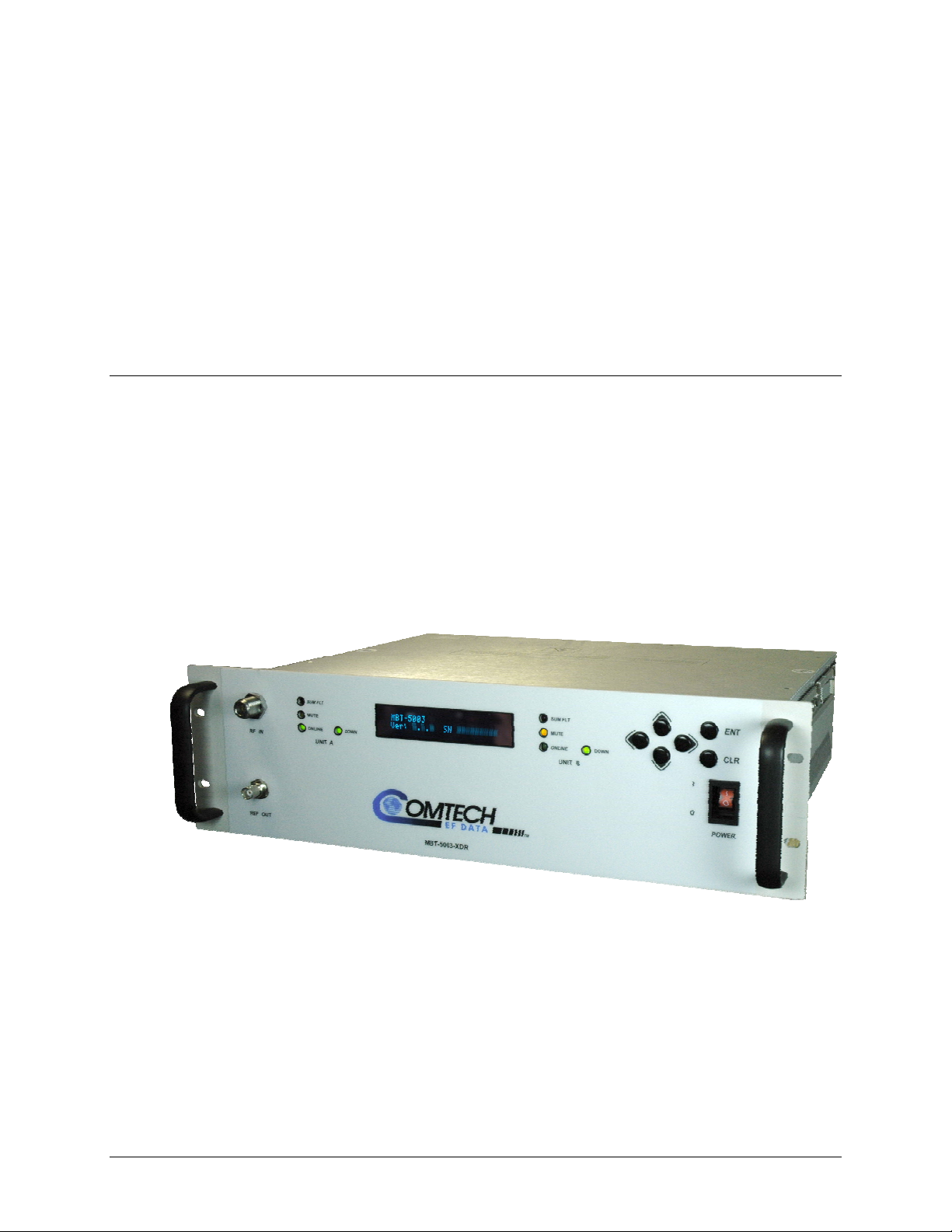
• The MBT-5003-XDR L-Band Down Converter (shown in Figure 1-1) incorporates
two internal down converter (BDC-5003) modules.
Figure 1-1. Comtech EF Data MBT-5003 L-Band Up/Down Converter
(MBT-5003-XDR shown)
1–1
Page 18
MBT-5003 L-Band Up/Down Converter System Revision 1
Introduction MN-MBT5003
1.2 Functional Description
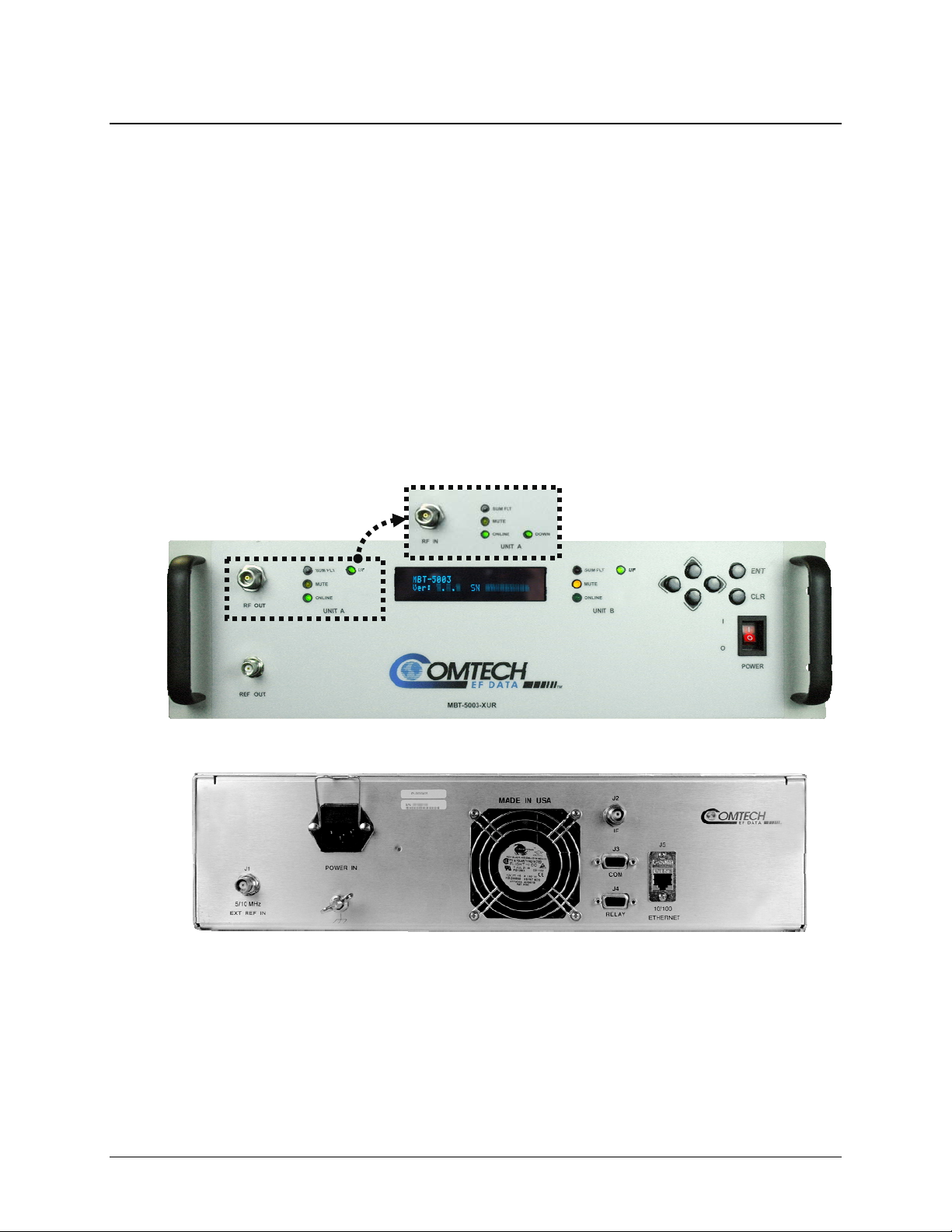
The MBT-5003’s 3RU-high, 19-inch wide chassis is designed for rack mounting into a standard
19-inch equipment rack. As shown in Figure 1-2, handles instal
ease of installation into and removal from the equipment rack.
All operator controls, indicators and displays for local and remote operation are located on the
front panel of the MBT-5003.
External interface connectors are located on the front and rear panels of the MBT-5003 chassis.
External equipment (e.g., a modem) is connected to each internal converter module via a
standard, off-the-shelf coaxial cable. A coaxial cable is also used to connect the output for each
module to RF equipment either at the same location or at the antenna location.
The system contains two diode “OR-ed” internal power supplies for increased reliability, and
microprocessor-based Monitor and Control (M&C) functions. Particular care has been given to
the RF performance of the MBT-5003 to facilitate its successful use in MIL-STD-188-164A
systems.
(MBT-5003-XDR Panel Detail)
MBT-5003 Front Panels
MBT-5003 Typical Rear Panel
led on the front panel facilitate
Figure 1-2. MBT-5003 Front and Rear Panels
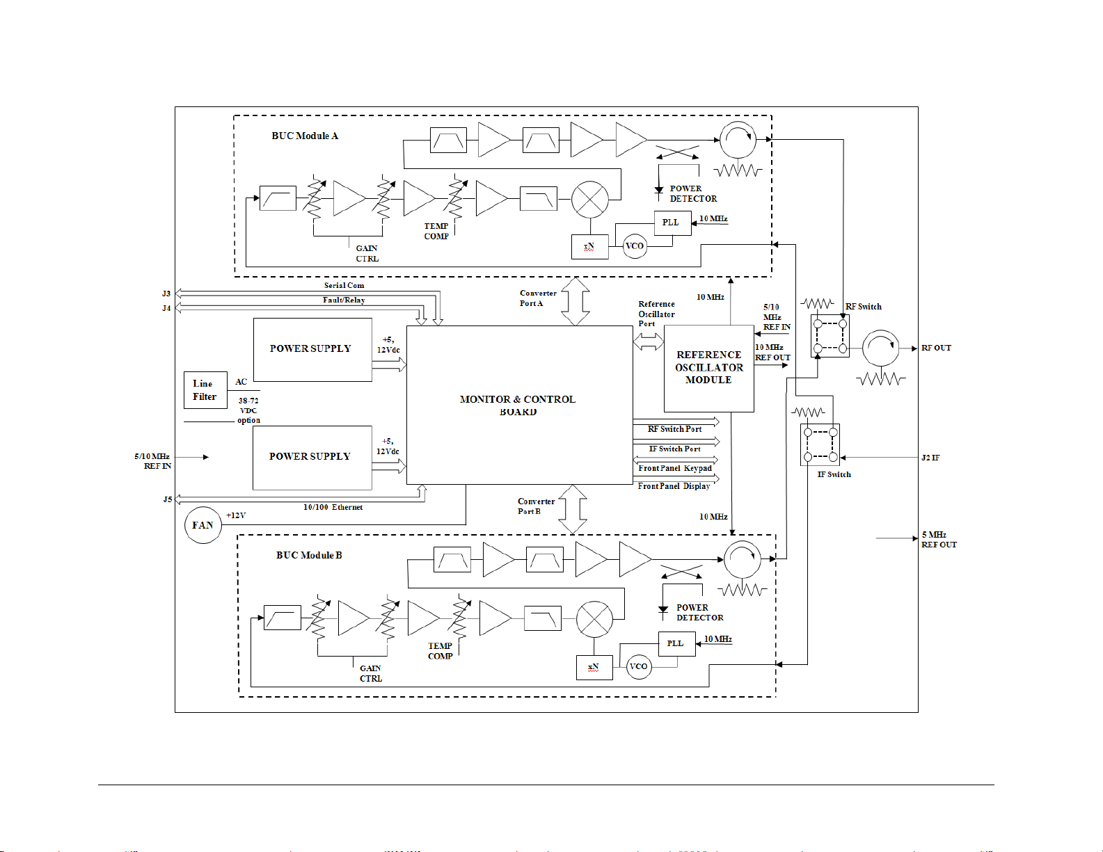
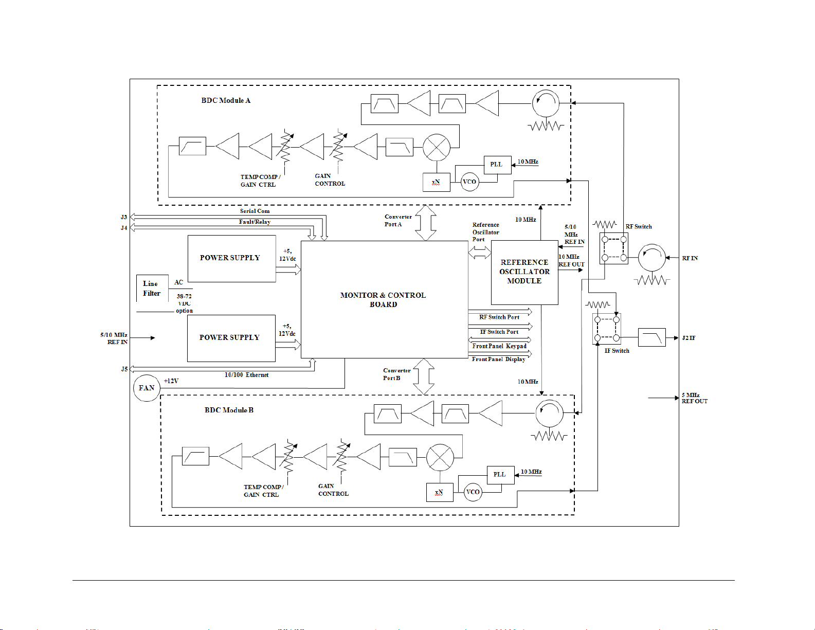
On the pages that follow, Figure 1-3 depicts the blo
ck diagram for the MBT-5003-XUR L-Band
Up Converter; Figure 1-4 shows the MBT-5003-XDR L-Band Down Converter’s
1–2
block diagram.
Page 19
MBT-5003 L-Band Up/Down Converter System Revision 1
Introduction MN-MBT5003
Figure 1-3. MBT-5003-XUR L-Band IF to X-Band RF Up Converter Block Diagram
1–3
Page 20
MBT-5003 L-Band Up/Down Converter System Revision 1
Introduction MN-MBT5003
Figure 1-4. MBT-5003-XDR L-Band IF to X-Band RF Down Converter Block Diagram
1–4
Page 21

MBT-5003 L-Band Up/Down Converter System Revision 1
Introduction MN-MBT5003
1.3 Features
• Meets or exceeds IESS-308/309
• Low phase noise
• Designed to facilitate operation within MIL-STD-188-164A systems
• Flexible configuration
• Guarded front panel power switch
• Output power monitor (up converter)
1.3.1 Block Up Converter (BUC-5003)
The BUC-5003 Block Up Converter module translates an L-Band (1000 to 1500 MHz) input
carrier to the desired X-Band (7900 to 8400 MHz) output frequency with an output level capable
of driving either solid state or tube-based amplifiers.
1.3.2 Block Down Converter (BDC-5003)
The BDC-5003 Block Down Converter module translates any X-Band (7250 to 7750 MHz)
signal to a corresponding L-Band (1000 to 15000 MHz) frequency.
1–5
Page 22

MBT-5003 L-Band Up/Down Converter System Revision 1
Introduction MN-MBT5003
1.4 Summary of Specifications
1.4.1 Physical & Environmental
Weight 20 lbs. (9.07 kg) Nominal
Dimensions (excluding connectors) 19” x 5.25” x 14” (482.6 x 133.35 x 355.6 mm) (Se e Figure 1-3)
Temperature
Operational Altitude 15,000 ft above sea level
Shock Normal commercial shipping and handling
Operating 32º to 132.8ºF (0º to 56ºC)
Non-operating (Storage) -58º to 158ºF (-50º to 70ºC)
1.4.2 Prime Power
AC Input
Voltage
Frequency 47 – 63 Hz
Dissipation
AC
DC (optional)
Up converter 100 Watts, typical
Down converter 80 Watts, typical
IEC-320 w/retainer
90 – 260 VAC
48 VDC
1.4.3 Monitor & Control
Serial M&C Interface TIA/EIA-485, 4-wire DB-9F
Alarm Form C, DB-9F
Remote Interface RJ-45 Ethernet
Physical Controls 6-button keypad entry
Display Vacuum Fluorescent Display (VFD), 24x2 alphanumeric
Status Indicators 5 LEDs per unit: SUM FLT, MUTE, ONLINE, UP, DOWN
1.4.4 Reference
External Input
Output
Internal 10 MHz
Setability
(by remote control)
Stability over Time
Stability over Temp
Resolution Better than 2.5 x 10⁻⁸
Range
5 or 10 MHz 5 ±5 dBm, BNC Female
5 MHz 10 ±5 dBm Front Panel, BNC Female
-9
±1 x 10
±1 x 10
>±5 x 10
/day (higher stability optional)
-8
-7
1–6
Page 23

MBT-5003 L-Band Up/Down Converter System Revision 1
Introduction MN-MBT5003
1.4.5 BUC-5003 Block Up Converter (featured on MBT-5003-XUR)
Output Frequency 7900-8400 MHz
Input Frequency 1000-1500 MHz
Frequency Sense No Inversion
Impedance
Input Return Loss 15 dB minimum
Output Return Loss 18 dB minimum
Input Connector Type ‘TNC’ Female
Output Connector Type ‘N’ Female
Full Band
Gain
Per 36 MHz
Per 20 MHz
0° to +56° C
Mute 80dB
User Attenuation Range 0-50 dB, in 0.25 dB steps
Output Power, P1dB 22 dBm minimum
Noise Figure 15 dB @ minimum attenuation
Intermodulation Distortion -30 dBc min w/2 output carriers @ 17 dBm each
AM/PM Conversion 0.1°/dB @ 0 dBm Output
Carrier Related -75 dBc (<-80 dBc, typical)
Spurious (In-band)
Non-Carrier Related -70 dBm
Lo Leakage -75 dBm
Related
60 Hz & Harmonics <-36 dBc (typically <-50 dBc)
Per 20 MHz BW 8 degrees p-p
Phase Non-linearity
Per 36 MHz BW 12 degrees p-p
Meets or exceeds MIL-STD-188-164A
100 Hz -68 dBc/Hz
1 kHz -78 dBc/Hz
Phase Noise
10 kHz -88 dBc/Hz
100 kHz -98 dBc/Hz
1 MHz -108 dBc/Hz
50Ω
38 ±2 dB nominal @ minimum attenuation
±1.0 dB
±0.50 dB
±0.35 dB
.75 dB/15°C (±1 dB, 0°-56 °C)
1–7
Page 24

MBT-5003 L-Band Up/Down Converter System Revision 1
Introduction MN-MBT5003
1.4.6 BDC-5003 Block Down Converter (featured on MBT-5003-XDR)
Input Frequency 7250-7750 MHz
Output Frequency 1000-1500 MHz
Frequency Sense No Inversion
Impedance
Input Return Loss 18 dB minimum
Output Return Loss 15 dB minimum
Input Connector Type ‘N’ Female
Output Connector Type ‘TNC’ Female
Full Band
Gain
Per 36 MHz
Per 20 MHz
0° to +56° C
Mute -80 dBm
User Attenuation Range 0 to 20 dB, in 0.25 dB steps
Signal Level 10 dBm maximum (non-damage)
Output Power, P1dB 20 dBm minimum
Noise Figure 15 dB @ minimum attenuation
Intermodulation Distortion -56 dBc w/2 carriers @ 0 dBm each, 3 dBm Total Output Pwr
AM/PM Conversion 0.1°/dB @ 0 dBm Output
Image Rejection 90dB
Carrier Related -75 dBc (<-80 dBc typical)
Spurious (In-band)
Non-Carrier Related -70 dBm
2nd Harmonic -20 dBc maximum (-40 dBc typical)
Lo Leakage -75 dBm
Related
60 Hz & Harmonics <-36 dBc (typically <-50 dBc)
per 20 MHz BW 3 degrees p-p
Phase Non-linearity
per 36 MHz BW 4 degrees p-p
Meets or exceeds MIL-STD-188-164A
100 Hz -68 dBc/Hz
1 kHz -78 dBc/Hz
Phase Noise
10 kHz -88 dBc/Hz
100 kHz -98 dBc/Hz
1 MHz -108 dBc/Hz
50Ω
38 ±2 dB nominal @ minimum attenuation
±1.0 dB
±0.50 dB
±0.35 dB
.75 dB/15°C (±1 dB, 0 to 56 °C)
1–8
Page 25

MBT-5003 L-Band Up/Down Converter System Revision 1
Introduction MN-MBT5003
1.5 Dimensional Envelope
Figure 1-5. MBT-5003 Dimensional Envelope
1–9
Page 26

MBT-5003 L-Band Up/Down Converter System Revision 1
Introduction MN-MBT5003
Notes:
1–10
Page 27

Chapter 2. INSTALLATION
2.1 Unpacking and Inspection
The MBT-5003 L-Band Up/Down Converter System and its Installation and Operation Manual
are packaged and shipped in a pre-formed, reusable cardboard carton containing foam spacing for
maximum shipping protection.
Inspect shipping containers for damage. If shipping containers are damaged, keep them until the
contents of the shipment have been carefully inspected and checked for normal operation.
Do not use any cutting tool that will extend more than 1” into the container
CAUTION
Unpack and inspect the MBT-5003 as follows:
Step Procedure
and cause damage to the converter.
1
2
3
4
5
6
7
Cut the tape at the top of the carton indicated by OPEN THIS END.
Remove the cardboard/foam space covering the MBT-5003.
Remove the MBT-5003, manual, and power cord from the carton.
Save the packing material for storage or reshipment purposes.
Inspect the equipment for any possible damage incurred during shipment.
Check the equipment against the packing list to ensure the shipment is correct.
Refer to the next section (Section 2.2) for installation instructions.
2–1
Page 28
MBT-5003 L-Band Up/Down Converter System Revision 1
Installation MN-MBT5003
2.2 Installation
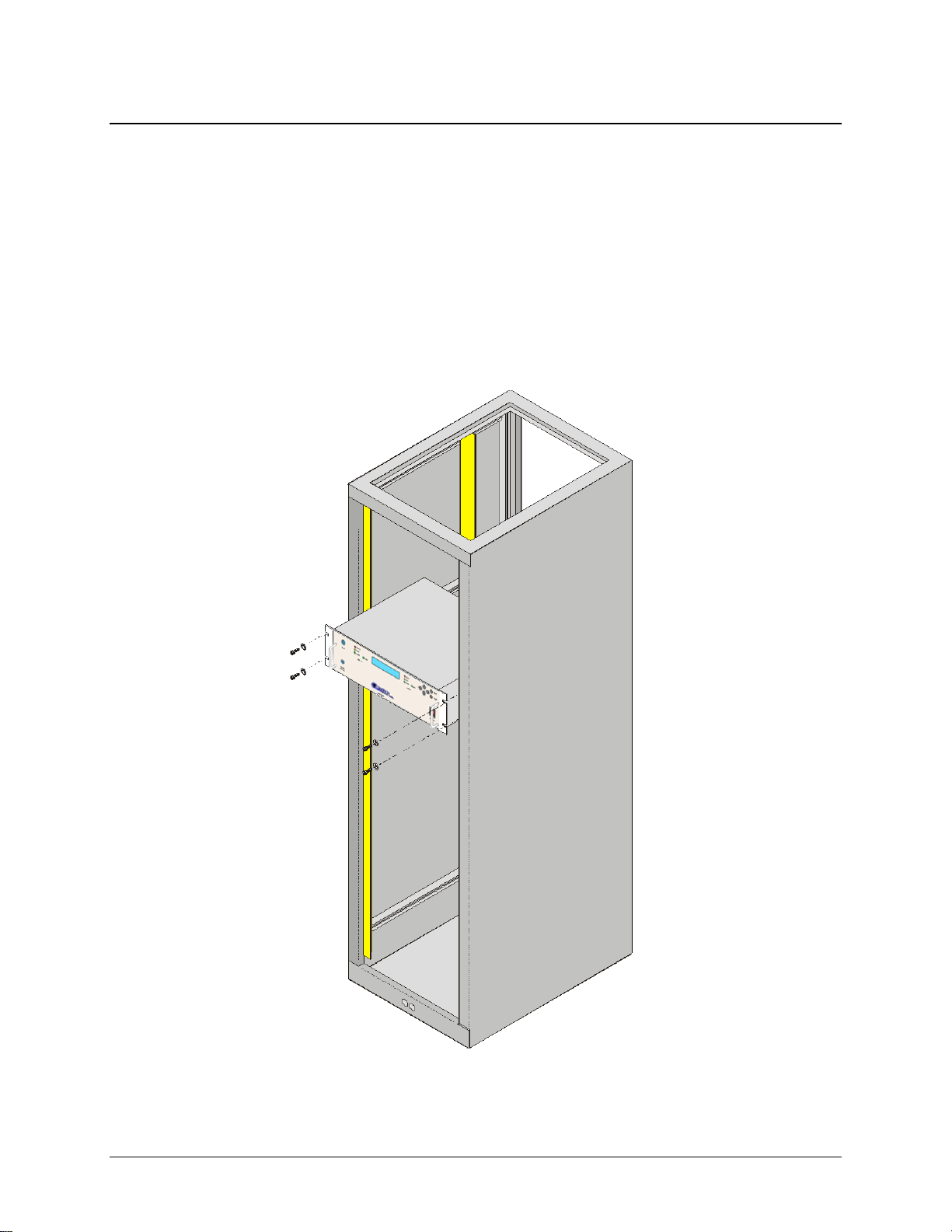
2.2.1 Standard Rack Mount Installation
The MBT-5003 is designed for installation in a standard 19-inch (48.26 cm) rack cabinet or
enclosure. Figure 2-1 p
The converter chassis requires 3RU (5.25 inches) of panel height space. Adequate air venti lation
should be provided on both sides of the rack-mounted equipment. In rack systems where there is
high heat dissipation, forced air cooling must be provided by top or bottom mounted fans or
blowers. Under no circumstance shou ld the highest internal rack temperature be allo wed to exceed
50°C (122°F).
rovides a “cut-away” side view of a typical MBT-5003 rack configuration.
Figure 2-1. Standard Rack Cabinet Installation
2–2
Page 29

MBT-5003 L-Band Up/Down Converter System Revision 1
Installation MN-MBT5003
2.2.2 Installation Using Optional Bearingless Rack Slide Set
If the converter is to be mounted on slides, install the optional bearingless rack slide set FP/SL0006
(Figure 2-2)
Install the components of the rack slide set as follows:
Step Procedure
using both included and use r-pr ovided m ounti ng har dware:
1
2
3
4
5
Using the provided mounting hardware, install the rack slides to either side of the
MBT-5003 chassis.
Using the provided mounting hardware, install the slide rail components into each
side of the rack cabinet.
Mount the unit into the equipment rack, ensuring that the slides properly engage the
cabinet-mounted slide rails.
Slide the unit into the rack cabinet until the front panel’s back surfaces abut the rack
cabinet’s front mounting rails.
Secure the unit to the rack cabinet front mounting rails using four user-provided
screws installed through the front panel mounting slots.
CEFD Part Number Description
FP/SL0006 Bearingless Rack Slide Set – 26”
Figure 2-2. Optional Bearingless Rack Slide Installation (FP/SL0006)
2–3
Page 30

MBT-5003 L-Band Up/Down Converter System Revision 1
Installation MN-MBT5003
2.3 Connect External Cables
Proceed to connect all external cables to the connectors identified in the next chapter (Chapter 3.
EXTERNAL CONNECTORS). Should difficulties occur, contact Comtech EF Data Customer
Support for assistance.
2–4
Page 31

Chapter 3. EXTERNAL
3.1 External Connectors Overview
As shown in Figure 3-1, connectors located on the front and rear panels of the MBT-5003
L-Band Up/Down Converter System provide all necessary external connections between the
converter and other equipment.
(MBT-5003-XDR Panel Detail)
MBT-5003 Front Panels
MBT-5003 Typical Rear Panel
CONNECTORS
Figure 3-1. MBT-5003 External Connectors
3–1
Page 32

MBT-5003 L-Band Up/Down Converter System Revision 1
External Connectors MN-MBT5003
3.2 MBT-5003 External Connectors
Table 3-1 summarizes the external connectors and identifies the chapter sections that provide
more detailed information. The rear panel connectors are typical for both the MBT-5003-XUR
Up Converter and MBT-5003-XDR Down Converter units. Front panel connectors, if not typical,
are identified as unique to either unit, both in the table as well as chapter sections that follow.
Table 3-1. MBT-5003 Front and Rear Panel External Connectors
Ref Des Name Sect Connector Type Function
N/A REF OUT
N/A RF OUT
N/A RF IN
J1
J2 IF
J3 COM
J4 RELAY
J5 10/100 ETHERNET
N/A POWER IN AC Plug
N/A GND
5/10 MHz
EXT REF IN
3.2.1 Front Panel Connectors
3.2.1.1
3.2.1.2
3.2.1.3
3.2.2.1
3.2.2.2
3.2.2.3
3.2.2.4
3.2.2.5
3.2.2.6
3.2.2.7
BNC (female)
Type ‘N’ (female)
Type ‘N’ (female)
BNC (female) External 5/10 MHz Reference Input
Type ‘TNC’ (female)
9-Pin Type ‘D’ (male) Serial Remote Control Interface
9-Pin Type ‘D’ (female) Form C Unit Alarm
RJ-45 10/100 Ethernet M&C
IEC Converter Power
#10-32 Stud Grounding
(Front panel – typical)
External 5/10 MHz Reference Output
(Front panel – MBT-5003-XUR only)
RF Output
(Front panel – MBT-5003-XDR only)
RF Input
Upconverted L-Band Input Signal
(MBT-5003-XUR only)
Downconverted L-Band Output Signal
(MBT-5003-XDR only)
3.2.1.1 REF OUT Connector, Type ‘BNC’ Female
The REF OUT interface is a type ‘BNC’ female coaxial connector provided on the
MBT-5003-XUR Up Converter and MBT-5003-XDR Down Converter front panels. It is
used to supply a 5 MHz signal from the chassis reference oscillator. The impedance is
matched for 50/75Ω, and provides an output level of 10 ±5 dBm.
3.2.1.2 RF OUT Connector (MBT-5003-XUR only), Type ‘N’ Female
The RF OUT connector is a type ‘N’ female coaxial connector provided only on the
MBT-5003-XUR Up Converter front panel. It provides the upconverted RF output
signal for customer use.
3–2
Page 33

MBT-5003 L-Band Up/Down Converter System Revision 1
External Connectors MN-MBT5003
3.2.1.3 RF IN Connector (MBT-5003-XDR only), Type ‘N’ Female
The RF IN connector is a type ‘N’ female coaxial connector provided only on the
MBT-5003-XDR Down Converter front panel. It provides the downconverted RF input
signal for customer use.
3.2.2 Rear Panel Connectors (Typical MBT-5003-XUR / MBT-5003-XDR)
3.2.2.1 J1 | 5/10 MHz EXT REF IN Connector
, Type ‘BNC’ Female
The J1 | 5/10 MHz EXT REF IN interface is a type ‘BNC’ female coaxial connector,
used to supply a master reference to the entire chassis. The input signal supplied here by
the user is used for phase-locking the internal 5/10MHz reference oscillator. The
impedance is matc hed for 50/75Ω, and requires an input level of 5 ±5 dBm.
3.2.2.2 J2 | IF Connector, Type ‘TNC’ Female
The J2 | IF connector is a type ‘TNC' female coaxial connector. For the
MBT-5003-XUR, it provides the L-Band input signal to be upconverted; for the
MBT-5003-XDR, it provides the L-Band output signal to be downconverted.
3.2.2.3 J3 | COM Connector (EIA-485 Interface), DB-9F
The J3 | COM EIA-485 4-wire interface is a 9-pin type ‘D’ (DB-9F) connector (the
mating connector is a DB-9M connector). The pinout specifications for EIA-485 are
contained in Table 3-2.
Table 3-2. J3 | COM – EIA-485 (4-Wire) Interface
Pin # Description
1 +Tx; Signal
2
3
4
5 GND; Ground
6 -TX; Signal Complement
7
8 +RX; Signal
9 -RX; Signal Complement
Note: Tx is the signal which transmits out of the MBT-5003.
3–3
Page 34

MBT-5003 L-Band Up/Down Converter System Revision 1
External Connectors MN-MBT5003
3.2.2.4 J4 | RELAY (Summary Fault Output) Connector, DB-9F
The J4 | RELAY summary fault output interface is a 9-pin type ‘D’ (DB-9F)
connector (the mating connector is a DB-9M connector). The pinout specifications
are contained in Table 3-3.
Table 3-3. J4 | RELAY –
Pin # Description
1 SUMFLT1_NC
2 SUMFLT1_NO
3 SUMFLT2_NC
4 SUMFLT2_NO
5 GND
6 SUMFLT1_COM
7 EXT_FLT_IN#
8 SUMFLT2_COM
9 NC
Summary Fault Output
Notes:
1. Pin 1 to Pin 6: Unit ‘A’ Fault
2. Pin 2 to Pin 6: Unit 'A' OK
3. Pin 3 to Pin 8: Unit ‘B’ Fault
4. Pin 4 to Pin 8: Unit ‘B’ OK
3.2.2.5 J5 | 10/100 Ethernet (M&C 10/100 BaseT Ethernet) Port, (RJ-45)
The J5 | 10/100 ETHERNET port provides a standard RJ-45 female interface for
10/100 BaseT Ethernet M&C (used for management and control via Telnet, HTTP,
and SNMP). It is also used for upgrading MBT-5003 firmware. This CAT5 receptacle
uses a UTP cable to connect to an Ethernet hub, router, switch, PC, etc. The pinout
specifications are contained in Table 3-4.
Table 3-4. J5 | 10/100 ETHERNET –
Pin # Description Direction
1 Tx+ Out
2 TX- Out
3 Rx+ In
4 N/A
5 N/A
6 Rx- In
M&C
3–4
Page 35

MBT-5003 L-Band Up/Down Converter System Revision 1
External Connectors MN-MBT5003
3.2.2.6 POWER IN (IEC Line Input AC Power) Connector
For continued operator safety, always replace the fuses with the correct type
IMPORTANT
Observe the following:
Input Power 290W maximum, 110W typical.
Input Voltage 100 to 240 volts AC, +6/-10% - autosensing
Connector Type IEC-320
Fuse Protection T2A (2.0A) Slow-blow
and rating.
A standard, detachable, non-locking, 3-prong power cord (IEC plug) supplies the
Alternating Current (AC) power to the converter.
AC Power Specifications
(total absolute max. range is 90 to 254 VAC)
Line and neutral fusing
20 mm type fuses
3.2.2.7 Ground Connector
A #10-32 stud is used for connecting a common chassis ground among equipment.
Note: The AC power connector provides the safety ground.
3–5
Page 36

MBT-5003 L-Band Up/Down Converter System Revision 1
External Connectors MN-MBT5003
Notes:
3–6
Page 37

Chapter 4. FLASH UPGRADING
4.1 Introduction
The MBT-5003 uses ‘Flash memory’ technology, and new firmware can be uploaded from an
external Microsoft Windows
and upgrade files containing the current version of firmware are available over the Internet
(Figure 4-1),
The complete upgrading process is as follows:
• New firmware can be downloaded via the Internet to an external PC.
• The upgrade can be performed without opening the MBT-5003 by simply connecting the
• The firmware update is transferred, via File Transfer Protocol (FTP), from the external
via e-mail, or on CD.
unit to the Ethernet port or serial port of the external PC.
PC to the MBT-5003.
®
-compatible computer. This makes software upgrading very simple,
Figure 4-1. Flash Upgrade via Internet
4–1
Page 38

MBT-5003 L-Band Up/Down Converter System Revision 1
Flash Upgrading MN-MBT5003
4.2 Ethernet FTP Upload Procedure
Step Procedure
Identify the reflashable product, firmware number, and version for download.
1
The current unit M&C version can be viewed at the top-level menu of the front panel display
(press the [CLR] key several times to view). The firmware information can also be found
within the SELECT: Utility Æ Firmware Æ Info Æ Image#1 or Image#2 menu trees.
Using serial remote control, the firmware revision levels may be obtained with the <0/SWR?
query. For more information, refer to Appendix A. REMOTE CONTROL.
Alternately, when using the Web Server Interface, the Bootrom, Bulk1 and Bulk2 firmware
loads may be viewed after selecting the Utility hyperlink, available under the Config page
tab. For more information, refer to Chapter 6.5. WEB SERVER INTERFACE.
2
Create a temporary folder (directory) on an external PC:
• For Windows Explorer: Select File > New > Folder to create a new folder, then
rename it from “New Folder” to "temp" or another convenient, unused name. Assuming
"temp" works, a "c:\temp" folder should now be created.
Note: The drive letter c: is used in this example. Any valid writable drive letter can be
used.
• For Windows Command-line: Click [Start] on the Windows taskbar, then click the
“Run...” icon (or, depending on Windows OS versions prior to Windows 95, click the
“MS-DOS Prompt” icon from the Main Menu). Then, to open a Command-line
window…
o For Windows 95 or Windows 98 – Type “command”.
o For any Windows OS versions later
“command”.
Alternately, from [Start], select All Programs > Accessories > Command
Prompt.
At the Command-line prompt (c:\>), type “mkdir temp” or “md temp” (without quotes – mkdir
and md stand for make directory). This is the same as creating a new folder from Windows
Explorer. There should now be a "c:\temp" subdirectory created (where c: is the drive letter
used in this example).
Download the correct firmware file to this temporary folder. As shown in Figure 4-1:
3
a) Go online to: www.comtechefdata.com;
b) Click on: Support tab;
c) Click on: Software Downloads drop-down or hyperlink from Support page;
d) Click on: Download Flash and Software Update Files icon;
e) Click on: (Select a Product Line) Converters hyperlink;
f) Click on: The MBT-5003 product hyperlink;
g) Select the appropriate firmware hyperlink.
About Firmware Numbers, File Versions, and Formats: The flashable files on the download
server are organized by product prefix; firmware number (verify that the correct firmware
number is known – see Step 1) and, where applicable, revision letter and release version.
The MBT-5003 firmware archive file hyperlink is FW-0000303x_V### (where ‘x’ denotes the
revision letter, and V### denotes the firmware version number).
than Windows 98 – Type “cmd” or
4–2
Page 39

MBT-5003 L-Band Up/Down Converter System Revision 1
Flash Upgrading MN-MBT5003
The current version firmware release is provided. If applicable, one version prior to the
3
(cont)
current release is also available. Be sure to identify and download the desired version.
The downloadable files are stored in two formats: *.exe (self-extracting) and *.zip
(compressed). Some firewalls will not allow the downloading of *.exe files. In this case,
download the *.zip file instead.
For additional help with "zipped" file types, refer to PKZIP for Windows, WinZip, or ZipCentral
help files. PKZIP for DOS is not supported due to file naming conventions.
Extract the files to the temporary folder on the PC. A minimum of two files should be
4
extracted:
a) FW-0000303x_#_#_#.bin – the bulk firmware file (where ‘x’ denotes the revision
letter, and #_#_# denotes the firmware version number).
b) ReleaseNotes_MBT5003_V###.pdf (where “###” denotes the firmware version
number).
5 Confirm that the files have been extracted to the specified temporary folder on the PC:
In Command-line, use “cd c:\temp” to change to the temporary directory created in Step 2,
then use the “dir” command to list the files extracted from the downloaded archive file.
Connect the client PC to the MBT-5003’s J5 | 10/100 Ethernet M&C port via a hub or a
6
switch, or directly to the PC with a crossover cable.
7
8
9
10
11
Send a “ping” command to the unit to verify the connection and communication:
First, determine the IP address of the unit remotely or by using the MBT-5003 Front Panel:
• Remotely – use the <0/IPA? command
• Via Front Panel – use the SELECT: Configure Æ Remote Æ EthernetConfig Æ
IP Address/ Range menu.
Then, using Command-line to PING: At the Command-line prompt, type “ping
xxx.xxx.xxx.xxx” (where ‘xxx.xxx.xxx.xxx’ is the Management IP address of the unit).
The results should confirm whether or not the unit is connected and communicating.
Initiate an FTP session with the unit (this example uses Command-line):
a) From the PC, type "ftp xxx.xxx.xxx.xxx" where "xxx.xxx.xxx.xxx" is the IP address
of the MBT-5003.
b) Enter the Admin User Name (there will be no prompt for a password) to complete
login.
c) Verify the FTP transfer is binary by typing "bin".
d) Type "prompt", then type "hash" to facilitate the file transfers.
Transfer the files from the temporary folder on the PC:
Type "put FW-0000303x_#_#_#.bin bulk:” to begin the file transfers. The destination “bulk:”
must be all lower-case. Approximately one minute is required to transfer the file.
Verify the file transfer:
a) The PC should report that the file transfer has occurred, and the display on the unit
will start reporting “Programming App Flash … Please wait”. After a few minutes, the
unit will display “Programming main FPGA … Please wait”.
b) Terminate the FTP session by typing "bye" and close the Command-line window.
c) Confirm that the new file was loaded by using the procedure in Step 1.
Change the desired image to boot.
From the MBT-5003 front panel menu: SELECT: Utility Æ Firmware Æ Select
Use the ◄ ► arrow keys to change to the other image, then cycle power to reboot the unit.
4–3
Page 40

MBT-5003 L-Band Up/Down Converter System Revision 1
Flash Upgrading MN-MBT5003
12
Notes:
Verify the new firmware version has booted by observing the firmware version displayed on
the MBT-5003 front panel:
MBT-5003
Version: #.#.# SN #########
Note: To load the second image, repeat Steps 8 through 11.
The Flash Upgrade Procedure is now complete.
4–4
Page 41

5.1 Introduction
Chapter 5. FRONT PANEL
OPERATION
Figure 5-1 identifies the key
System front panel. The front panel features (from left) two sets of four Light-Emitting Diode
(LED) indicators, a Vacuum Fluorescent Display (VFD), a six-button keypad, and the prime
power switch.
The function and behavior of the LED indicators, keypad, and VFD is described in detail in this
chapter. The keypad comprises six individual keyswitches. The user can fully control and monitor
the operation of the MBT-5000 from the front panel using the keypad and display. The user enters
data via the keypad, and messages are displayed on the VFD. The LEDs indicate, in a summary
fashion, the status of the unit.
Unit A LED
Indicators
Figure 5-1. MBT-5003 Front Panel (MBT-5003-XUR shown)
Vacuum Fluorescent
Display (VFD)
operational features of the MBT-5003 L-Band Up/Down Converter
Unit B LED
Indicators
Keypad
Power
Switch
5–1
Page 42

MBT-5003 L-Band Up/Down Converter System Revision 1
Front Panel Operation MN-MBT5003
5.1.1 Switch Power On
Prior to turning power on to the unit, check to ensure that installation is
complete, and verify that the MBT-5003 is connected to the proper prime power
source, RF Input, and RF Output.
For more information, refer to Chapter 2. INSTALLATION and Chapter 3.
EXTERNAL CONNECTORS.
Switch on the unit and verify that the cooling fan is operational, the LED indicators illuminate as
expected, and the Vacuum Fluorescent Display is readable.
5.1.2 LED Indicators
MBT-5003-XUR MBT-5003-XDR
Unit A / Unit B LED Array Unit A / Unit B LED Array
The following table defines the operational condition, when lit, of the front panel LED indicator
arrays (four LEDs each per Units A and B, as depicted above):
LED Color Operational Condition (When Lit)
SUM FLT Red
MUTE Amber
ON LINE Green
UP Green
DOWN Green
The designated unit has active faults.
The designated unit is in Mute Mode.
The designated unit is operational when lit.
(MBT-5003-XUR only) The designated unit is operating as an Up Converter when lit.
(MBT-5003-XDR only) The designated unit is operating as a Down Converter when lit.
5–2
Page 43

MBT-5003 L-Band Up/Down Converter System Revision 1
Front Panel Operation MN-MBT5003
5.1.3 Keypad
The keypad comprises six individual key switches. They have a
positive ‘click’ action, which provides tactile feedback. The
function of the front panel keypad is as follows:
The ENT (ENTER) key is used to select a displayed function or to execute a
modem configuration change.
(Up, Down)
(Left, Right)
IMPORTANT
The CLR (CLEAR) key is used to back out of a selection or to cancel a
configuration change which has not been executed using ENT. Pressing CLR
generally returns the display to the previous selection.
These arrows are used primarily to change configuration data (numbers), at the
current cursor position. Occasionally, they may be used to scroll through a
number of choices at the current cursor position. Most of the menus (space
permitting) include arrow key hints to guide the user.
These arrows are used to move to the next selection or to move the cursor
position. Most of the menus (space permitting) include arrow key hints to guide
the user.
The keypad has an auto-repeat feature. If a key is held down for more than 1
second, the key action will repeat, automatically, at the rate of 15 keystrokes
per second. This is particularly useful when editing numeric fields, with many
digits, such as frequency or data rate.
5.1.4 Vacuum Fluorescent Display (VFD)
The MBT-5003 features a Vacuum Fluorescent
Display (VFD). The VFD is an active display
showing two lines of 24 characters each. It
produces a blue light, the brightness of which
can be controlled by the user. Compared to a Liquid Crystal Display (LCD), it has greatly
superior viewing characteristics and does not suffer problems of viewing angle or contrast.
On most menu screens, the user will observe a flashing solid block cursor, which blinks at a onceper-second rate. This indicates the currently selected item, digit, or field. Where this solid block
cursor would obscure the item being edited (e.g., a numeric field) the cursor will automatically
change to an underline cursor.
If the user were to display the same screen for weeks at a time, the display could become ‘burnt’
with this image. To prevent this, the unit has a ‘screen saver’ feature, which will activate after a
few minutes. The top line of the VFD will display the Circuit ID, and the bottom line will display
‘Press any key...’. The message moves from right to left across the screen, then wraps
around. Pressing any key will restore the previous screen.
5–3
Page 44

MBT-5003 L-Band Up/Down Converter System Revision 1
Front Panel Operation MN-MBT5003
5.2 Opening Screen
MBT-5003
Ver: #.#.# SN #########
This screen is displayed whenever power is first applied to the unit. When the prime power is
turned on, this VFD ‘splash’ display indicates the converter model number – i.e., ‘MBT-5003’ –
along with the version number of the firmware installed, and the serial number assigned for the
unit in use.
The opening screen may be accessed from any location within the MBT-5003 menu structure by
pressing the CLR key repeatedly. Otherwise, press any key to access the SELECT: (Main)
menu.
5–4
Page 45

MBT-5003 L-Band Up/Down Converter System Revision 1
Front Panel Operation MN-MBT5003
5.3 SELECT: (Main) Menu
SELECT: Config Monitor
Info Utility Test
Figure 5-2 illustrates the hierarchal structure of the SELECT: (Main) menu tree. The converter
commands are in a tree structured menu format designed for access and execution of all control
functions, and to prevent the execution of an invalid entry by the operator.
Figure 5-2. MBT-5003 Principal Menu Tree
5–5
Page 46

MBT-5003 L-Band Up/Down Converter System Revision 1
Front Panel Operation MN-MBT5003
Use the ◄ ► arrow keys to select from the choices shown, then press ENT. The following table
identifies each menu branch available from the SELECT: (Main) menu, its content section in this
chapter, and the functional description of each branch:
Menu Branch Sect Description
Config 5.3.1
Monitor 5.3.2
Info 5.3.3
Utility 5.3.4
Test 5.3.5
(Configuration) Available submenus permit the user to fully configure the MBT-5003.
Available submenus permit the user to monitor the alarm status of the unit, to view
the log of stored events, and to display the Receive Parameters screen.
(Information) Available submenus permit the user to view information on the unit,
without having to go into configuration screens.
Available submenus permit the user to perform miscellaneous functions, such as
setting the Real-time clock, adjusting the display brightness, etc.
Runs diagnostics tests on the front panel LEDs and VFD to verify operation.
5.3.1 SELECT: Config (Configuration)
CONFIG: Remote FltRec
ConvA ConvB RefAdj Redun
Use the ◄ ► arrow keys to select from the submenu choices shown, then press ENT. The following
table identifies each submenu available from the SELECT: Config menu branch – typical for
Converter Unit A or Unit B – its content section in this chapter, and functional description of each
submenu:
Submenu Sect Functional Description
(Remote Control) Permits the user to define whether the unit is being controlled
Remote 5.3.1.1
FltRec 5.3.1.2
ConvA
ConvB
RefAdj 5.3.1.4
Redun 5.3.1.5
5.3.1.3
locally or remotely, and identifies the unit address, interface type, and rate and
format of the baud parameters.
(Fault Recovery) Permits the user to configure Fault Recovery (AFR) in Auto or
Manual mode.
(Converter Unit A or B) Displays the current configuration of the selected converter,
including the frequency, attenuation, and slope.
(Ref-Osc Adjust) Permits the user to adjust the reference oscillator.
(Redundancy) Permits the user to identify the redundancy state and mode (refer to
Appendix B. MBT-5003 REDUNDANCY OPERATION for further information).
5–6
Page 47

MBT-5003 L-Band Up/Down Converter System Revision 1
Front Panel Operation MN-MBT5003
5.3.1.1 CONFIG: Remote (Remote Control)
Remote Control: Local
Serial Ethernet (◄ ► E)
Select Local, Serial, or Ethernet using the ◄ ► arrow keys, then press ENT.
CONFIG: Remote Control Æ Local
If Remote Control: Local is selected, then remote control will be disabled. Remote monitoring is
still possible.
CONFIG: Remote Control Æ Serial
If Remote Control: Serial is selected:
Serial Config: Interface
Address Baudrate
Select Interface, Address, or Baudrate using the ◄ ► arrow keys, then press ENT.
If Serial Config: Interface is selected:
M&C Bus Interface:
RS485-2W RS485-4W
Select RS485-2W (2-wire) or RS-485 (4-wire) using the ◄ ► arrow keys, then press ENT.
If Serial Config: Address is selected:
Remote Address: 0001
(◄ ► ▲ ▼ E)
The valid range of addresses is from 1 to 9997. Use the ◄ ► arrow keys to select the
character to edit, then the ▲ ▼ arrow keys to edit the value of the digit, then press ENT.
If Serial Config: Baudrate is selected:
Local M&C Bus Baud Rate:
19200 Baud (▲ ▼ E)
Edit the baud rate of the remote control bus, connected locally to the M&C computer. The
value is changed using the
baud are available. Press ENT when done.
Note: The asynchronous character format is FIXED at 8 data bits, 1 stop bit, no parity (8-N-1).
▲ ▼ arrow keys. Values of 2400, 4800, 9600,19200, and 38400
CONFIG: Remote Control Æ Ethernet
If Remote Control: Ethernet is selected:
Ethernet Config: Gateway
Address MAC SNMP (◄ ► E)
Select Gateway, Address, MAC, or SNMP using the ◄ ► arrow keys, then press ENT.
5–7
Page 48

MBT-5003 L-Band Up/Down Converter System Revision 1
Front Panel Operation MN-MBT5003
If Ethernet Config: Gateway is selected:
Ethernet IP Gateway:
192.168.001.002 (◄ ► ▲ ▼)
To edit the IP Gateway Address for the Ethernet M&C port for this unit, first use the ◄ ►
arrow keys to select the digit to edit, then the ▲ ▼ arrow keys to edit the value of that digit.
Press ENT when done.
If Ethernet Config: Address is selected:
Ether IP Address/Range:
192.168.001.002/24(◄ ►▲ ▼)
To edit the IP Address and Range for the Ethernet M&C port for this unit, first use the ◄ ►
arrow keys to select the digit to edit, then the ▲ ▼ arrow keys to edit the value of that digit.
Press ENT when done.
If Ethernet Config: MAC is selected:
M&C Port MAC Address:
00-06-B0-00-01-06
This read-only menu shows the unit MAC address. Once the MAC address has been noted,
press ENT or CLR to return to the previous menu.
If Ethernet Config: SNMP is selected:
SNMP:
Community Traps (◄ ► E)
Select Community or Traps using the ▲ ▼ arrow keys, then press ENT.
If SNMP: Community is selected:
SNMP Community:
Read Write Trap (◄ ► E)
Select Read, Write, or Trap using the ▲ ▼ arrow keys, then press ENT.
If Read is selected:
Read Community: (◄ ►▲▼ E)
public
The user may view or edit the SNMP Read Community string. To edit, first use the ◄
►arrows keys to select the character to edit, then the ▲ ▼ arrows keys to edit that
character. Press ENT when done.
If Write is selected:
Write Community: (◄ ►▲▼ E)
private
The user may view or edit the SNMP Write Community string. To edit, first use the ◄
►arrows keys to select the character to edit, then the ▲ ▼ arrows keys to edit that
character. Press ENT when done.
5–8
Page 49

MBT-5003 L-Band Up/Down Converter System Revision 1
Front Panel Operation MN-MBT5003
If Trap is selected:
Trap Community: (◄ ►▲▼ E)
comtech
The user may view or edit the SNMP Trap Community string. To edit, first use the ◄
►arrows keys to select the character to edit, then the ▲ ▼ arrows keys to edit that
character. Press ENT when done.
If SNMP: Traps is selected:
SNMP Trap IP Address:
IP1 IP2 Version
Select IP1, IP2, or Version using the ◄ ► arrow keys to, then press ENT.
If SNMP Trap IP Address: IP1 or IP2 is selected:
Trap IP #1:
000.000.000.000 (◄ ►▲▼ E)
Trap IP #2:
000.000.000.000 (◄ ►▲▼ E)
The user may edit the Trap Destination’s IP Addresses. To edit, first use the ◄ ►
arrow keys to select the digit to edit, then the ▲ ▼ arrow keys to edit the value of that
digit. Press ENT when done.
Note: If both Trap IP Addresses are 000.000.000.000, it means Traps are disabled.
If SNMP Trap IP Address: Version is selected:
Trap Version:
SNMPv1 SNMPv2 (◄ ► E)
Select the trap version – SNMPv1 or SNMPv2 – using the ▲ ▼ arrow keys, then
press ENT.
5.3.1.2 CONFIG: FltRec (Fault Recovery)
Fault Recovery: Manual
Automatic
Select Manual or Automatic using the ◄ ► arrow keys, then press ENT.
5.3.1.3 CONFIG: ConvA or ConvB (Converter Unit ‘A’ or Converter Unit ‘B’)
Converter X
Mute/Freq Attenuation
Where ‘X’ is the selected converter – i.e., Converter (Unit) A or Converter (Unit) B – select
Mute/Freq or Attenuation using the ◄ ► arrow keys, then press ENT.
5–9
Page 50

MBT-5003 L-Band Up/Down Converter System Revision 1
Front Panel Operation MN-MBT5003
If Mute/Freq is selected, and the unit is an MBT-5003-XUR Up Converter:
CONFIG CnvX:
Tx=On
Use the ▲ ▼ arrows keys to set Tx as ON or OFF (mute), then press ENT.
If Mute/Freq is selected, and the unit is an MBT-5003-XDR Down Converter:
CONFIG CnvX:
Rx=On
Use the ▲ ▼ arrows keys to set Rx as ON or OFF (mute), then press ENT.
Typical for both the MBT-5003-XUR and MBT-5003-XDR units, if Attenuation is selected:
CONFIG CnvX: Offst=+2.00
Attenuation = 00.00 dB
Note: Offst (Offset) will display only if the unit is an offline unit.
5.3.1.4 CONFIG: RefAdj (Reference Oscillator Adjustment)
Reference Frequency
Adjust: 087
Adjust the reference oscillator by using the ◄ ► arrow keys to select the digit to edit, then the ▲
▼ arrow keys to edit the value of that digit. Press ENT when done.
The default Reference Frequency tuning adjustment is 087, with allowable values from 0 to 255.
5.3.1.5 CONFIG: Redun (Redundancy)
Redundancy:
Disable/Enable Force
Note: While the user may select Disable/Enable or Force using the ◄ ► arrow keys, the
Disable option is nonfunctional with the MBT-5003.
Redundancy Mode:
Disable Enable (◄ ► E)
Should the user attempt to select Disable using this menu, the following message displays:
Redundancy is always
Enabled for this unit.
The Disable/Enable menu will redisplay with the cursor set to Enable. Press ENT or CLR
to return to the previous menu.
If Force is selected:
Press ENTER to Force
Converter A to Standby
As the display instructs, press ENT to force the redundant unit into standby mode.
Refer to Appendix B. MBT-5003 REDUNDANCY OPERATION for further information
on this feature.
5–10
Page 51

MBT-5003 L-Band Up/Down Converter System Revision 1
Front Panel Operation MN-MBT5003
5.3.2 SELECT: Monitor
Note: Low Noise Amplifier (LNA) operation is not supported by the MBT-5003. The LPT
selection on this submenu is therefore nonfunctional.
Monitor: Faults Mask
Event-Log LPT
Use the ◄ ► arrow keys to select from the submenu choices shown, then press ENT. The following
table identifies each submenu available from the SELECT: Monitor menu branch – typical for
Converter Unit A or Unit B – its content section in this chapter, and functional description of each
submenu:
Submenu Sect Functional Description
Faults 5.3.2.1
Mask 5.3.2.2
Event-Log 5.3.2.3
Displays the active faults for the base unit and the converters.
Permits the user to configure Alarm Mask (MSK) conditions.
Display stored events. Also permits the user to clear the events.
5.3.2.1 MONITOR: Faults
Live Faults: Unit ConvA
ConvB (◄ ► E)
Select Unit, ConvA, or ConvB using the ◄ ► arrow keys, then press ENT.
If Unit is selected, the highest level fault for the base unit will appear. If no Unit faults exist,
the message “
Unit Fault:
No Errors
Press ENT to return to the previous menu.
If ConvA or ConvB is selected, the highest fault for the converter will appear. If no converter
faults exist, the message “
ConvA Fault:
No Errors
No Errors” is displayed:
No Errors” is displayed:
Press ENT to return to the previous menu.
5.3.2.2 MONITOR: Mask
Note: The Power selection on this submenu is operable only when the MBT-5003-XUR is
optionally configured with the Power Monitor option. Low Noise Amplifier (LNA) operation is
not supported by the MBT-5003 – the LNA selection is therefore nonfunctional.
Alarm Mask: Power ExtRef
ConvA ConvB LNA (◄ ► E)
5–11
Page 52

MBT-5003 L-Band Up/Down Converter System Revision 1
Front Panel Operation MN-MBT5003
Select Power (when applicable), ExtRef, ConvA, or ConvB using the ◄ ► arrow keys, then press
ENT.
For each menu selection, three typical options are available. Using the ExtRef menu as an example:
Ext Ref Lock Detect:
Fault Alarm Masked(◄ ► E)
Select Fault, Alarm, or Masked using the ◄ ► arrow keys, then press ENT to return to the
previous menu.
5.3.2.3 MONITOR: Event-Log (Stored Events)
Stored Events: View
Clear-All (◄ ► E)
Select View or Clear-All using the ◄ ► arrow keys, then press ENT.
If View is selected:
Log015 05/23/08 09:27:15
Fault – FPGA Checksum
The user may scroll backwards or forwards through the entries in the event log by using the ▲ ▼
arrow keys. Press ENT or CLR to return to the previous menu.
The event log can store up to 300 events. When a fault condition occurs, it is time-stamped and
put into the log. Similarly, when the fault condition clears, this is also recorded, as shown per the
following example:
Log015 05/23/08 10:45:35
Clear – FPGA Checksum
If Clear-All is selected:
Clear all Stored Events
No Yes (◄ ► E)
If Clear-All is selected, the user is prompted to choose No or Yes. Use the ◄ ► arrow keys, then
press ENT. If the user selects Yes, the event log is cleared, and the user is taken directly back to
the previous menu. However, if there are faults present on the unit at this time, they will be retime-stamped, and new log entries will be generated.
5–12
Page 53

MBT-5003 L-Band Up/Down Converter System Revision 1
Front Panel Operation MN-MBT5003
5.3.3 SELECT: Info
INFO:Remote ConvA ConvB
PSA PSB RefOsc
The Info menu branch displays read-only information on the current configuration of the unit.
Use the
table identifies each submenu available from the SELECT: Info menu branch – typical for Converter
Unit A or Unit B – its content section in this chapter, and functional description of each submenu:
◄ ► arrow keys to select from the submenu choices shown, then press ENT. The following
Submenu Sect Functional Description
Remote 5.3.3.1
ConvA
ConvB
PSA
PSB
RefOsc 5.3.3.4
5.3.3.2
5.3.3.3
(Remote Control) Displays if the unit is in Local or Remote mode and gives details of the
interface type selected, etc.
Displays the temperature and RF power for Converter Unit A or Converter Unit B.
Displays the 12V, 8V, and 5V power supplies for Power Supply A or Power Supply B.
Displays the raw voltage of the voltage tuning monitor, and the external reference status.
5.3.3.1 INFO: Remote (Remote Control)
This screen displays if the unit is in Local or Remote mode and gives details of the interface type
selected, etc. For example:
Remote M&C: 100BaseTx
IP Addr: 192.168.001.004
Press ENT or CLR to return to the previous menu.
5.3.3.2 INFO: ConvA or ConvB (Converter Unit ‘A’ or Converter Unit ‘B’)
Where ‘X’ is the selected converter – i.e., Converter (Unit) A or Converter (Unit) B – this screen
displays the unit temperature and, when an MBT-5003-XUR Up Converter is optionally
configured with the Power Monitor feature, the RF power. For example:
ConvX: Temp = +34.1 C
RF Power = +10.0 dBm
Press ENT or CLR to return to the previous menu.
5.3.3.3 INFO: PSA or PSB (Power Supply ‘A’ or Power Supply ‘B’)
Where ‘X’ is the selected power supply – i.e., Power Supply (Unit) A or Power Supply (Unit) B –
this screen displays the 12V, 8V, and 5V power supply. For example:
Power Supply X:
12V=12.2 8V=08.3 5V=05.3
Press ENT or CLR to return to the previous menu.
5–13
Page 54

MBT-5003 L-Band Up/Down Converter System Revision 1
Front Panel Operation MN-MBT5003
5.3.3.4 INFO: RefOsc (Reference Oscillator)
Note: This selection is used for debugging purposes only.
This screen displays the raw voltage of the voltage tuning monitor, and the external reference
status. For example:
Ref Osc: Vtune = 04.7
Ext Ref: N/A
Press ENT or CLR to return to the previous menu.
5.3.4 SELECT: Utility
Note: Low Noise Amplifier (LNA) operation is not supported by the MBT-5003. The LNA
selection on this submenu is therefore nonfunctional.
UTILITY: Date/Time CID
Display Firmware LNA
Use the ◄ ► arrow keys to select from the submenu choices shown, then press ENT. The following
table identifies each submenu available from the SELECT: Utility menu branch – typical for
Converter Unit A or Unit B – its content section in this chapter, and functional description of each
submenu:
Submenu Sect Functional Description
Date/Time 5.3.4.1
CID 5.3.4.2
Display 5.3.4.3
Firmware 5.3.4.4
Edits the Real-Time Clock time and date settings
Edits the 24-character Circuit ID string.
Adjusts the brightness level of the Vacuum Fluorescent Display (VFD).
Displays the installed internal firmware and permits user the boot using a selected
firmware image.
5.3.4.1 UTILITY : Date/Time (Set Real-time Clock)
Edit Real-Time Clock:
12:00:00 10/31/10(◄ ►▲ ▼ E)
To edit the time and date settings of the real-time clock, first select the digit to be edited using the
◄ ► arrow keys, then change the value of that digit using the ▲ ▼ arrow keys. Press ENT
when done.
5–14
Page 55

MBT-5003 L-Band Up/Down Converter System Revision 1
Front Panel Operation MN-MBT5003
5.3.4.2 UTILITY : CID (Circuit ID)
Edit Circuit ID:
24 CHARACTER TST MESSAGE
To edit the Circuit ID string: On the bottom line, first use the ◄ ► arrow keys to select the
character to edit, then change that character using the ▲ ▼ arrow keys.
A maximum of 24 characters are available, as follows:
[Space] ( ) * + - , . / 0-9 and A-Z.
Once the ID string is composed, press ENT.
5.3.4.3 UTILITY : Display (VFD Display Brightness)
Display Brightness:
100%
To edit the display brightness: Use the ▲ ▼ arrow keys to select a brightness value of 25%,
50%, 75%, or 100%. Press ENT when the brightness is suitable.
5.3.4.4 UTILITY : Firmware
THESE MENUS ARE INTENDED FOR DIAGNOSTIC PURPOSES ONLY. DO NOT
CHANGE AN IMAGE UNLESS OTHERWISE INSTRUCTED BY COMTECH EF
IMPORTANT
This series of submenus permits the user to view information about the MBT-5003 internal
firmware. The converter can store two complete firmware images; either image is selectable for
loading the next time the unit reboots.
Firmware Images:
Info Select (◄ ► E)
Select either Info or Select using the ◄ ► arrow keys, then press ENT.
UTILITY: Firmware Æ Info
If Info is selected:
Firmware Info: Bootrom
Image#1 Image#2
Select Bootrom, Image#1 or Image#2 using the ◄ ► arrow keys, then press ENT to view the
information.
DATA CUSTOMER SUPPORT.
Each image is further broken down as follows (where Image#X denotes Image#1 or
Image#2):
Image#X: Bulk APP FPGA
Select Bulk, App, or FPGA using the ◄ ► arrow key, then press ENT.
5–15
Page 56

MBT-5003 L-Band Up/Down Converter System Revision 1
Front Panel Operation MN-MBT5003
If, for example, Bulk is selected, a screen formatted similar to the following example is
displayed:
Bulk: FW-0000303
2.#.# MM/DD/YY
UTILITY: Firmware Æ Select
If Select is selected:
Current Active Image: #1
Next Reboot Image: #1 #2
The top line shows the current active image. From the bottom line, select the Next Reboot Image
(i.e., the image that will be active the next time the unit is rebooted) as #1 or #2 using the
arrow keys. Press ENT when done.
◄ ►
5.3.5 SELECT: Test
TEST: Lamptest
Press ENT to begin the diagnostics run on the front panel’s Light-Emitting Diode arrays and
Vacuum Fluorescent Display. The LEDs for Unit A and Unit B will cycle, and the VFD will briefly
generate a test pattern.
Once the test has run, press CLR to return to the SELECT: (Main) menu.
5–16
Page 57

Chapter 6. ETHERNET
MANAGEMENT
6.1 Overview
The sections that follow describe the functionality of the MBT-5003 Ethernet Interface. Refer to the
Remote Commands Specifications tables found in Appendix A. REMOTE CONTROL for
detailed descriptions of the configuration parameters featured on the individual Web pages depicted
in this section.
6.2 Ethernet Management Interface Protocols
The MBT-5003 100BaseT/10BaseTx Ethernet Management Interface supports three (3) different
management protocols:
• SNMP with public and private MIB
• Telnet interface for remote product M&C
• Web Server (HTTP) Interface for complete product management
For SNMP, Telnet, or Web Server operation, the MBT-5003 must be configured
with the Ethernet control option. Via the front panel, select CONFIG: Remote
IMPORTANT
Control Æ Ethernet. See Chapter 5. FRONT PANEL OPERATION for further
information.
6.3 SNMP Interface
The Simple Network Management Protocol (SNMP) is an application-layer protocol designed to
facilitate the exchange of management information between network devices. The MBT-5003
SNMP agent supports both SNMPv1 and SNMPv2c.
For proper SNMP operation, the MBT-5003 MIB files must be used with the
associated version of the MBT-5003 M&C. Refer to the MBT-5003 FW Release
IMPORTANT
Notes for information on the required FW/SW compatibility.
6–1
Page 58

MBT-5003 L-Band Up/Down Converter System Revision 1
Ethernet Management MN-MBT5003
6.3.1 Management Information Base (MIB) Files
MIB files are used for SNMP remote management and consist of Object Identifiers (OIDs). Each
OID is a node that provides remote management of a particular function. A MIB file is a tree of
nodes that is unique to a particular device.
The following MIB files are associated with the MBT-5003:
MIB File/Name Description
FW-0000235-.mib
ComtechEFData
Root MIB file
FW-0000101- .mib
MBT-5003 MIB file
FW-0000102- .mib
MBT-5003 Traps
MIB file
ComtechEFData MIB file gives the root tree for ALL Comtech EF Data products
and consists of only the following OID:
Name: comtechEFData
Type: MODULE-IDENTITY
OID: 1.3.6.1.4.1.6247
Full
path: iso(1).org(3).dod(6).internet(1).private(4).enterprises(1).comtechEFData(6247)
Module: ComtechEFData
MIB file consists of all of the OID’s for management of the amplifier functions
Trap MIB file is provided for SNMPv1 traps common for MBT-5003.
These MIB files should be compiled in a MIB Browser or SNMP Network Monitoring System server.
Note: As noted previously, the SNMP agent supports both SNMPv1 and SNMPv2c. The
“Traps” file only needs to be compiled if SNMPv1 traps are to be used.
6.3.2 SNMP Community Strings
The MBT-5003 uses community strings as a password scheme that provides authentication before
gaining access to the MBT-5003 agent’s MIBs.
In SNMP v1/v2c, the community string is sent unencrypted in the SNMP packets. Caution must
be taken by the network administrator to ensure that SNMP packets travel only over a secure and
private network if security is a concern. A packet sniffer can easily obtain the community string
by viewing the SNMP traffic on the network.
The community string is entered into the MIB Browser or Network Node Management software
and is used to authenticate users and determine access privileges to the SNMP agent.
The user defines three Community Strings for SNMP access:
• Read Community default = public
• Write Community default = private
• Trap Community default = comtech
6–2
Page 59

MBT-5003 L-Band Up/Down Converter System Revision 1
Ethernet Management MN-MBT5003
6.3.3 SNMP Traps
The MBT-5003 has the ability to send out SNMP traps when certain events occur in the unit. The
MBT-5003 sends out traps when a fault occurs in the unit. A trap is sent both when a fault occurs
and is cleared.
The MBT-5003 supports both SNMPv1 traps and SNMPv2 notifications. Which style of traps
the MBT-5003 sends can be configured by the user using the MBT-5003SNMPTrapVersion OID.
The following are the MIB2 v1traps / v2 notifications that the MBT-5003 supports:
MIB2 SNMPv1 trap: Authentication Failure 5
MIB2 SNMPv2 notifications: Authentication Failure 1.3.6. 1.6.3.1.1.5.5
The following tables are the Faults v1 traps / v2 notifications that the MBT-5003 supports.
Faults SNMPv1 traps:
mbt5000BaseUnitFaultV1 6247501
mbt5000ConvAFaultV1 6247502
mbt5000ConvBFaultV1 6247503
Faults SNMPv2 notifications:
mbt5000BaseUnitFaultEvent
1.3.6.1.4.1.6247.50.2.1.1
mbt5000ConvAFaultEvent 1.3.6.1.4.1.6247.50.2.1.2
mbt5000ConvBFaultEvent
1.3.6.1.4.1.6247.50.2.1.3
6–3
Page 60

MBT-5003 L-Band Up/Down Converter System Revision 1
Ethernet Management MN-MBT5003
6.4 Telnet Interface
The MBT-5003 provides a Telnet interface for the purpose of Equipment M&C via the standard
equipment Remote Control protocol.
The Telnet interface requires user login at the Administrator level and Read/Write level.
The example shown to the
right illustrates the login
procedure:
Once logged into the
Telnet interface as
Administrator, the user can
access the standard remote
control interface defined in
Appendix A. REMOTE
CONTROL, as shown in
example to the right:
There is a disadvantage when using Windows DOS as Telnet Client. Since Windows DOS cannot
translate a ‘\r’ to a ‘\r\n’ for the messages coming from Telnet Server, the multi-line command
response (for example, FRW? response) will be displayed as one line, with the latt er lines ove rwriti ng
the previous lines. In order to view the full response messages, CEFD recommends using
HyperTerminal configured as Telnet Client.
Configure HyperTerminal as follows:
1. Use TCP/IP (Winsock)
nstead of COM1 or COM2 for
the connection, as per the
example to the near right.
2. ASCII Setup (FileÆ
Properties ÆSettingsÆASCII
Setup):
Check the "Send line ends
with line feeds" option in the
ASCII Sending section and the
"Append line feeds to
incoming line ends" option in
the ASCII Receiving section, as
per the example to the far right.
6–4
Page 61

MBT-5003 L-Band Up/Down Converter System Revision 1
Ethernet Management MN-MBT5003
3. Login and remote
command execution
via HyperTerminal
configured as Telnet
Client appears as p er
the example to the
right:
6.5 Web Server (HTTP) Interface
Refer to the Remote Commands Specifications tables found in Appendix A. REMOTE
CONTROL for detailed descriptions of the configuration parameters featured on the individual
Web pages shown in this chapter.
6.5.1 Web Server Page Introduction
The embedded Web Server application provides the user with an easy to use interface to
configure and monitor all aspects of the MBT-5003. These Web pages have been designed for
optimal performance when using Microsoft’s Internet Explorer Version 5.5 or higher (the
examples shown use Internet Explorer Version 6.0).
The user can fully control and monitor base operations of
the MBT-5003 from the Web Server Interface. By rolling
the cursor over the navigation tabs located at the top of
each page (right), the user can select from the available
nested hyperlinks.
6.5.2 Enabling the Web Server Interface
Note: The IP Address can be found by following the pathway CONFIG: Remote Control Æ
Ethernet Æ Address.
To enable the Web Server Interface in the MBT-5003 using only a 100BaseTx remote interface
(this assumes the user’s PC is configured to run the Microsoft Windows OS):
1. Select Start, then Run,
then type “cmd” to open
the command prompt
window:
See Chapter 5. FRONT PANEL OPERATION for further information.
6–5
Page 62

MBT-5003 L-Band Up/Down Converter System Revision 1
Ethernet Management MN-MBT5003
2. Start a Telnet session
with the unit at the
default IP address of
192.168.1.5:
3. Enter the Telnet username
and password (the default
for both parameters is
comtech):
Failure to enter the correct User name and Password will return the user to a blank login
screen.
6.5.3 Web Server Interface Access
Note: The IP Address can be found by following the pathway CONFIG: Remote Control Æ
Ethernet Æ Address.
1. From the PC, type http://192.168.1.5 (the
default IP address for the MBT-5003) into
the Address area of the Web browser:
2. The Login window will appear, and the user is prompted to
type a User Name and Password:
Default User Name – comtech
Default Password – comtech
Type the User Name and Password, then click [OK].
Failure to enter the correct
User name and Password will
return the user to a blank
Login window. If multiple
invalid logins are attempted,
the browser will display the
following access error
message:
See Chapter 5. FRONT PANEL OPERATION for further information.
6–6
Page 63

MBT-5003 L-Band Up/Down Converter System Revision 1
Ethernet Management MN-MBT5003
6.5.4 Web Server Interface “Splash” Page
Once the valid IP address and
login information has been
entered, the MBT-5003 Web
Server Interface “Splash” page
is displayed:
The options available through the MBT-5003 Web Server Interface are illustrated via the following
menu tree:
Home Admin Config Status
Home Access MBT Events
Contact SNMP Utility Status
Support Redundancy
6.5.5 Web Server Page Descriptions
The sections and subsections that follow detail the Web pages accessible via hyperlink from the
“Splash” page navigation tabs shown in Sect. 6.5.4:
Sect. 6.5.5.1 Home Pages
Sect. 6.5.5.2 Admin (Administration) Pages
Sect. 6.5.5.3 Config (Configure MBT-5003) Pages
Sect. 6.5.5.4 Status Pages
6–7
Page 64

MBT-5003 L-Band Up/Down Converter System Revision 1
Ethernet Management MN-MBT5003
6.5.5.1 Home Pages
Select the Home, Contact, or Support hyperlink to continue.
6.5.5.1.1 Home | Home
Figure 6-1. MBT-5003 Home | Home page
From any location within the Web Server Interface, the user can select the Home tab and/or
hyperlink to return back to this page.
6–8
Page 65

MBT-5003 L-Band Up/Down Converter System Revision 1
Ethernet Management MN-MBT5003
6.5.5.1.2 Home | Contact
Figure 6-2. Home | Contact page
The ‘Home | Contact’ page (Figure 6-2) provides
basic contact information to reach Comtech
EF Data Sales and Customer Support via phone and e-mail or Web site hyperlinks.
6–9
Page 66

MBT-5003 L-Band Up/Down Converter System Revision 1
Ethernet Management MN-MBT5003
6.5.5.1.3 Home | Support
For this page to operate correctly, the MBT-5003’s administrator is required to
specify the SMTP server, domain name, and destination on the Admin | Access
IMPORTANT
page (see Sect. 6.5.5.2.1).
Figure 6-3. Home | Support page
The MBT-5003 ‘Home | Support’ page (Figure 6-3) uses SMTP (Sim
ple Mail Transport
Protocol) to allow the user to e-mail questions about or problems with the MBT-5003 to Comtech
EF Data IP Product Support (cdmipsupport@comtechefdata.com
).
Fill in the appropriate user information as required under Contact Information; the Problem
Report text window allows up to 256 characters maximum.
Once the Contact Information is entered and a message composed in the Problem Report text
window, click [Submit Email] to send the message.
6–10
Page 67

MBT-5003 L-Band Up/Down Converter System Revision 1
Ethernet Management MN-MBT5003
6.5.5.2 Admin Pages
Select the Access or SNMP hyperlink to continue.
The Admin pages are available only to users who have logged in using the
IMPORTANT
Administrator Name and Password.
6.5.5.2.1 Admin | Access
Figure 6-4. Admin | Access page
The ‘Admin | Access’ page (Figure 6-4)
provides the means to set up and maintain user names,
passwords, the e-mail server, and the host IP addresses to facilitate communication with the
MBT-5003 Web Server Interface.
Network Maintenance
• IP Gateway, IP Address/Range: Enter the desired IP Gateway Address and IP Address/
Range in these text boxes.
MAC Address (read-only): The MAC is set at the factory to a guaranteed unique address
•
that cannot be modified by the user.
Once the desired configuration settings have been made in this section, click [Change IP
Address] to save these changes. If it is desired to revert back to the previously assigned IP
Gateway and IP Address/Range, the user should instead click [Reset].
6–11
Page 68

MBT-5003 L-Band Up/Down Converter System Revision 1
Ethernet Management MN-MBT5003
System Account Access Information
• Admin, Read/Write, and Read Only Names and Passwords:
The factory defaults for these names/passwords are:
o Admin comtech/comtech
o Read/Write opcenter/1234
o Read Only monitor/1234
Note the following:
o These Name fields can be any alphanumeric combination with a maximum
length of 10 characters.
o These Password fields can be any alphanumeric combination with a maximum
length of 10 characters.
• SMTP Server: Specify the mail server IP address from where you want to send the
e-mail.
• SMTP Domain Name / Destination: The Administrator can assign the SMTP Domain
Name and Destination. This is required if the e-mail feature of the Support Page (Sect.
6.5.5.1.3) is to be used.
o For SMTP Domain Name, specify the domain of the e-mail server (usually
found to the right of the @ symbol in an e-mail address).
o For SMTP Domain Destination, specify the e-mail recipient name (usually
found to the left of the @ symbol in an e-mail address).
Once the desired configuration settings have been made in this section, click [Submit Access] to
save these changes. Otherwise, click [Reset] if it is desired to revert back to the previously
assigned System Account Access Information.
6–12
Page 69

MBT-5003 L-Band Up/Down Converter System Revision 1
Ethernet Management MN-MBT5003
6.5.5.2.2 Admin | SNMP
Figure 6-5. Admin | SNMP page
The ‘Admin | SNMP’ page (Figure 6-5) sets and
returns administration information for the
MBT-5003 Simple Network Management Protocol (SNMP) feature.
Simple Network Management Operational Status: Using the drop-down menu, select the
Simple Network Management operational setting as Enabled or Disabled.
The SNMP Read and Write Community String fields can be any combination of characters and
a length of 0 - 20 characters:
• The factory default for the Read Community String parameter is public.
• The factory default Write Community String is private.
Enable Authentication Trap: Using the drop-down menu, select the Enable Authentication Trap
operational setting as Enabled or Disabled.
The Administrator can assign up to two SNMP Trap IP addresses and one SNMP Trap
Community String. The SNMP Trap Community String field can be any combination of
characters and a length of 0 - 20 characters:
• The factory default for the Trap Community String is comtech.
Trap Version: Using the drop-down menu, select the SNMP Trap Version as SNMPv1 or
SNMPv2.
For details pertaining to the remaining configuration parameters available on this page, refer to
Sect. 6.3 SNMP INTERFACE.
Once the desired SNMP assignations have been made on this page, click [Submit SNMP] to save
these changes. Otherwise, click [Reset] if it is desired to revert back to the previously assigned
SNMP.
6–13
Page 70

MBT-5003 L-Band Up/Down Converter System Revision 1
Ethernet Management MN-MBT5003
6.5.5.3 Config Pages
Select the MBT, Utility, or Redundancy hyperlink to continue.
6.5.5.3.1 Config | MBT
Note: Low Noise Amplifier (LNA) operation is not supported by the MBT-5003. The Converter
A LNA and LPT, Converter B LNA and LPT, and Calibrate LNA Current sections of this
page are therefore nonfunctional.
Figure 6-6. Config | MBT page
The ‘Config | MBT’ page (Figure 6-6)
provides the means to configure the communications,
operations, and alarms/faults handling for the MBT-5003 base unit and individual converters.
6–14
Page 71

MBT-5003 L-Band Up/Down Converter System Revision 1
Ethernet Management MN-MBT5003
Serial
• Interface Type: Using the drop-down menu, select the operating interface type as RS-485
2-wire or RS-485 4-wire.
• Remote Address: Enter a valid physical remote address from 0001 to 9999.
• Baud Rate: Using the drop-down menu, select the operating baud rate as 2400, 4800,
9600, 19200, or 38400 baud
Once the desired configuration settings have been made in this section, click [Change Serial
Configuration] to save these changes. Otherwise, click [Reset] if it is desired to revert back to
the previously assigned interface settings.
Base Unit
Fault Recovery: Using the drop-down menu, select the Fault Recovery function as either
•
Manual or Automatic.
• Reference Frequency Adjust: Enter a numeric value from 0 to 255 to adjust the
reference oscillator tuning voltage. The default value is set to 87.
Once the desired configuration settings have been made in this section, click [Change Base Unit
Configuration] to save these changes.
Converter A / B
Typical for both sections:
• Attenuation (dB): Enter a valid attenuation level (00.00 to 20.00 dB) in 0.25 dB steps.
• Attenuation Offset (Converter A only): Enter a valid value, in dB, for the attenuation
offset.
• Mute: Using the drop-down menu, select the Mute function as either On or Off.
• Frequency: This text field is fixed at N/A for the MBT-5003.
Once the desired configuration settings have been made in this section, click [Change Convert X
Configuration] (where ‘X’ designates Converter A or Converter B) to save these changes.
6–15
Page 72

MBT-5003 L-Band Up/Down Converter System Revision 1
Ethernet Management MN-MBT5003
6.5.5.3.2 Config | Utility
Figure 6-7. Config | Utility page
The ‘Config | Utility’ page (Figure 6-7) is used t
parameters.
o configure MBT-5003 base unit operating
Date and Time
• The user may enter a date in the form MM/DD/YY (where MM = month [01 to 12],
DD = day [01 to 31], and YY = year [00 to 99]).
• The user may enter a time using HH:MM:SS format (where HH = hour [00 to 23],
MM = minutes [00 to 59], and SS = seconds [00 to 59]).
Click [Change Date/Time] as needed once the desired date and time have been entered here.
Circuit ID
The user may create a Circuit ID string of up to 24 characters. Click [Change CID] once the
desired string has been entered here.
Current Active Firmware Image (read-only)
The selected Current Active Firmware Image is identified here. In this example, Image 2 is the
Current Active Firmware Image.
Next Reboot Image
Using the drop-down menu, select the Next Reboot Image as 1 or 2, then press [Submit] when
done.
Perform Soft Reboot
Click [Reboot Now] to reboot the MBT-5003 using the Current Active Firmware Image.
6–16
Page 73

MBT-5003 L-Band Up/Down Converter System Revision 1
Ethernet Management MN-MBT5003
6.5.5.3.3 Config | Redundancy
For detailed information about 1:1 Redundant operations, see Appendix B.
MBT-5003 REDUNDANCY OPERATION.
IMPORTANT
Figure 6-8. Config | Redundancy page
The ‘Config | Redundancy’ page (Figure 6-8) is used to configur
e the MBT-5003’s Redundancy
Switch operation.
Redundancy Mode
Use the drop-down menu to Enable or Disable Redundancy Mode, then click [Change
Redundancy Mode] to update MBT-5003 operation to the current Redundancy Mode status.
Redundancy Switch Override
Click [Force Converter A Offline] to force the Converter A into standby mode.
6–17
Page 74

MBT-5003 L-Band Up/Down Converter System Revision 1
Ethernet Management MN-MBT5003
6.5.5.4 Status Pages
The hyperlinks available under the ‘Status’ tab provide the user access to event logging, operational
statistics and status windows. Select the Events or Stat us hype rlin k to conti nue.
6.5.5.4.1 Status | Events
Figure 6-9. Status | Events page
The ‘Status | Events’ page (Figure 6-9) provi
stored events, and provides the user with a means to define the MBT-5003 alarm parameters that
determine how those events are triggered.
des the user with all pertinent information about
Current Faults (Display only the highest)
This read-only window displays the running tally of stored events log for the entire MBT-5003
unit (i.e., Base Unit and Converters A and B).
Unread Stored Events
This read-only scrollable window displays the unread stored events log in sequential, datestamped format. A running tally of the number of unread stored events is displayed in the window
header. The unit returns and displays the five oldest stored events in the alarm log. All events that
are read from the log are also automatically removed from the log.
The user has the ability to manage the Unread Stored Events window as follows:
• Read Next Five Events: Select to display the next five unread stored events in the log.
6–18
Page 75

MBT-5003 L-Band Up/Down Converter System Revision 1
Ethernet Management MN-MBT5003
• Clear Events Log: Select to clear all stored events from the log.
• Initialize Events Pointer: Select to reset the internal pointer to allow queries to start at
the beginning of the stored events log.
Once a selection has been made, click [Submit] to execute the choice – the window will update
according to the selection made.
Alarm Mask
Note the following:
• Low Noise Amplifier (LNA) operation is not supported by the MBT-5003. All alarm masks
associated with this feature are therefore nonfunctional.
• The Low Forward RF Power alarm masks are valid, when optionally configured, only for
the MBT-5003-XUR Up Converter.
Using the drop-down menus, select each alarm as Fault, Alarm or Masked for:
• Low Forward RF Power (MBT-5003-XUR only)
• Converter A Not Inserted
• External Reference Lock Detected
• Converter B Not Inserted
Once the desired configuration settings have been made in this section, click [Change Alarm
Mask] to save these changes. Otherwise, click [Reset] if it is desired to revert back to the
previously assigned Alarm Mask settings, the user should instead click.
6–19
Page 76

MBT-5003 L-Band Up/Down Converter System Revision 1
Ethernet Management MN-MBT5003
6.5.5.4.2 Status | Status
Figure 6-10. Status | Status page
The ‘Status | Status’ page (Figure 6-10) is a read-only page that provides
the user with all
pertinent information about the MBT-5003 operating configuration:
• General Information, including product identification (i.e., model and serial numbers),
active software image information, active operating temperature, and power readings for
the Base Unit, Converter A, and Converter B.
Note the following:
o Low Noise Amplifier (LNA) operation is not supported by the MBT-5003. All
parameter readings associated with this feature are therefore invalid.
o Valid Conv A/ConvB Forward RF Power readings are provided only if the
MBT-5003-XUR Up Converter is optionally configured with the Power Monitor
feature. These parameters otherwise will display as N/A if the pertinent converter
is an MBT-5003-XDR Down Converter.
• Firmware Information for Bootrom, Bulk Image#1 and Bulk Image #2.
• Part Numbers for the Base Unit, Converter A, and Converter B.
6–20
Page 77

A.1 Introduction
This appendix describes the protocol and message command set for remote monitor and control of the MBT-5003 L-Band Up/Down
Converter System.
The electrical interface is an EIA-485 multi-drop bus for the control of many devices, and data is transmitted in asynchronous serial form,
using ASCII characters. Control and status information is transmitted in packets of variable length, in accordance with the structure and
protocol defined in later sections.
The Remote Control connector pinout is shown in Chapter 3.2.6 COM (EIA-485 Interface), J3 (DB-9F).
NOTE
A.2 EIA-485
For applications where multiple devices are to be monitored and controlled, a full-duplex (4-wire plus ground) EIA-485 is preferred. Halfduplex (2-wire plus ground) EIA-485 is possible, but is not preferred. In full-duplex EIA-485 communication, there are two separate,
isolated, independent, differential-mode twisted pairs, each handling serial data in different directions.
Appendix A. REMOTE CONTROL
It is assumed that a 'Controller' device (a PC or dumb terminal) transmits data in a broadcast mode via one of the pairs. Many 'Target'
devices are connected to this pair, and all simultaneously receive data from the Controller. The Controller is the only device with a linedriver connected to this pair; the Target devices have only line-receivers connected.
A–1
Page 78

MBT-5003 L-Band Up/Down Converter System Revision 1
Appendix A MN-MBT5003
In the other direction: On the other pair, each Target has a tri-state line driver connected; the Controller has a line-receiver connected. All
the line drivers are held in high-impedance mode until one – and only one – Target transmits back to the Controller. Each Target has a
unique address; each time the Controller transmits, the address of the intended recipient Target is included in a framed 'packet' of data. All
of the Targets receive the packet, but only one (the intended) will reply. The Target enables its output line driver and transmits its return
data packet back to the Controller in the other direction on the physically separate pair.
EIA-485 (full duplex) summary:
• Two differential pairs - one pair for Controller-to-Target, one pair for Target-to-Controller.
• Controller-to-Target pair has o ne line driver (C ontrol ler), a nd all Ta rgets have line- receivers .
• Target-to-Controller pair has one line receiver (Controller), and a ll Targets have tri-state drivers.
A.3 Basic Protocol
With EIA-485 mode, all data is transmitted as asynchronous serial characters, suitable for transmission and reception by a UART. The
asynchronous character format is 8-N-1 (8 data bits, no parity, one stop bit). The supported baud rates are 2400, 4800, 9600, 19200, and
38400 baud.
All data is transmitted in framed packets. The Controller is assumed to be a PC or ASCII dumb terminal that is in charge of the process of
monitor and control. The Controller is the only device that is permitted to initiate, at will, the transmission of data. Targets are only
permitted to transmit when they have been specifically instructed to do so by the Controller.
All bytes within a packet are printable ASCII characters, less than ASCII code 127. In this context, the Carriage Return and Line Feed
characters are considered printable.
All messages from Controller-to-Target require a response, with one exception: This will be either to return data that has been requested by the
Controller, or to acknowledge reception of an instruction to cha nge th e configurat ion of the Target.
A–2
Page 79

MBT-5003 L-Band Up/Down Converter System Revision 1
r
Appendix A MN-MBT5003
A.4 Packet Structure
Controller-to-Target
Start of Packet Target Address Address Delimiter Instruction Code Code Qualifier
<
ASCII code 60
(1 character)
(4 characters)
/
ASCII code 47
(1 character)
ASCII codes 61 or 63
(3 characters)
Example: <0412/MUT=1{CR}
Target-to-Controlle
Start of Packet Target Address Address Delimiter Instruction Code Code Qualifier
>
ASCII code 62
(1 character) (4 characters)
/
ASCII code 47
(1 character) (3 characters)
ASCII codes 61,63, 33
Example: >0412/MUT=1{CR}{LF}
A.4.1 Start of Packet
= or ?
(1 character)
=, ?, !, or *
or 42
(1 character)
Optional
Arguments
(n characters)
Optional
Arguments
(From 0 to n
characters)
End of Packet
Carriage Return
ASCII code 13
(1 character)
End of Packet
Carriage Return,
Line Feed
ASCII codes
13,10
(2 characters)
Controller-to-Target: This is the character '<' (ASCII code 60).
Target-to-Controller: This is the character '>' (ASCII code 62).
Because this is used to provide a reliable indication of the start of packet, these two characters may not appear anywhere else within the
body of the message.
A–3
Page 80

MBT-5003 L-Band Up/Down Converter System Revision 1
Appendix A MN-MBT5003
A.4.2 Target Address
Up to 9,999 devices can be uniquely addressed; in EIA-485 applications, the permissible range of values is 1 to 9999. The address is
programmed into a Target unit using the remote control port.
Each block converter module has its own address:
Module Address
MBT-5003 Base
Block Converter A Base + 1
Block Converter B Base + 2
If several devices share an EIA-485 bus, it must be noted that the MBT-5003 will require three addresses, and should be spaced apart
accordingly.
The Controller sends a packet with the address of a Target – the destination of the packet. When the Target
responds, the address used is the same address, to indicate to the Controller the source of the packet. The
IMPORTANT
Controller does not have its own address.
A.4.3 Address Delimiter
This is the “forward slash” character '/' (ASCII code 47).
A.4.4 Instruction Code
This is a three-character alphabetic sequence that identifies the subject of the message. Wherever possible, the instruction codes have been
chosen to have some significance. For example,
FRE is for Operating FREquency,
FBU is for Force Backup Unit, etc.
This aids in the readability of the message if seen in its raw ASCII form. Upper case and lower case alphabetic characters may be used (AZ and a-z, ASCII codes 65 – 90 and 97-172).
A–4
Page 81

MBT-5003 L-Band Up/Down Converter System Revision 1
Appendix A MN-MBT5003
A.4.5 Instruction Code Qualifier
This single character further qualifies the preceding instruction code. Code Qualifiers obey the following rules:
1. From Controller-to-Target, the only permitted values are ‘=’ and ‘?’:
=
(ASCII code 61)
?
(ASCII code 63)
The = code is used as the assignment operator, and is used to indicate that the parameter defined by the preceding byte
should be set to the value of the argument(s) which follow it.
For example, in a message from controller to target, MUT=1 would mean ‘enable the mute function’.
The ? code is used as the query operator, and is used to indicate that the target should return the current value of the
parameter defined by the preceding byte.
For example, in a message from controller to target, MUT? denotes ‘return the current state of the mute function.’
2. From Target-to-Controller, the only permitted values are ‘=’, ‘?’, ‘!’, ‘*’, ‘#’, a nd ‘$’:
=
(ASCII code 61)
?
(ASCII code 63)
!
(ASCII code 33)
The = code is used in two ways:
First, if the controller has sent a query code to a ta rget (for example: MUT? meaning 'is mut e e nab le d or d isabled ?'), th e targ et
would respond with MUT=x, where x represents the state in question: 1 being enabled, and 0 being disabled.
Second, if the controller sends an instruction to set a param eter to a particular value, then, providing the value sent in the
argument is valid, the target will acknowledge the message by replying with MUT= (with no message arguments).
The ? code is only used as follow s:
If the controller sends an instruction to set a parameter to a particular value, then, if the value sent in the argu ment is not vali d,
the target will acknowledge the message by r eplying (for example) with MUT? (without message arguments). This indicates
that there was an error in the argument of the message sent by the controller.
The ! code is only used as follows:
If the controller sends an instruction code that t he target does not recognize, the target will acknowledge the message by
echoing the invalid instruction, followed by the ! character with. Example: XYZ!
*
(ASCII code 42)
The * code is only used as follows:
If the controller sends an instruction to set a parameter to a particular value, and, if the value sent in the argument is vali d,
however the target is in the wrong mode (for example, standby mode in redundancy configuration) that it will not permit that
particular parameter to be changed at that time, then the target will acknowledge the message by replying (for example)
with MUT* (without message arguments).
A–5
Page 82

MBT-5003 L-Band Up/Down Converter System Revision 1
Appendix A MN-MBT5003
#
(ASCII code 35)
$
(ASCII Code 36)
The # code is only used as follows:
If the controller sends an instruction code which the target cannot currently perform because of hardware resource issues,
then the target will acknowledge the message by echoing the invalid instruction, followed by the # character. This response
can only occur if the operator sends two or more ‘hardware configuration’ type commands without allowing adequate time
between commands for the hardware to be configured. For example, if the operator issued commands to change both the
frequency and the attenuation with less than 100 milliseconds between commands, and if this response is returned, then
the command has not been accepted and the operator must resend the command.
The $ code is only used as follows:
The target acknowledges the message indicating that this block converter is not installed.
A.4.6 Optional Message Arguments
Arguments are not required for all messages. Arguments are ASCII codes for the characters 0 to 9 (ASCII codes 48 to 57), period (ASCII
code 46), and comma (ASCII code 44).
A.4.7 End of Packet
Controller-to-Target: This is the 'Carriage Return' character (ASCII code 13).
Target-to-Controller: This is the two-character sequence 'Carriage Return', 'Line Feed'. (ASCII code 13, and ASCII code 10).
Both indicate the valid termination of a packet.
A.5 Configure Mute Mode
Turns the mute mode ON or OFF. When mute mode is OFF (default), the unit will mute upon changing RF frequency. When mute mode
is ON, the unit will remain whatever its mute state upon changing RF frequency.
Command Details
Configure Mute Mode: <DEV/MUT=y'cr' DEV = Conv A or Conv B address, y = 0 or 1
Confirmation: >DEV/MUT='cr''lf'
Mute Mode Status: <DEV/MUT?'cr'
Confirmation: >DEV/MUT=y'cr''lf'
A–6
Page 83

MBT-5003 L-Band Up/Down Converter System Revision 1
XXA
XXA
X
A
X
A
AXX
A
XXA
XXA
X
A
KXX
A
XXA
XXA
X
A
X
A
X
A
X
A
X
A
X
A
XXA
XXA
X
A
X
A
X
A
Appendix A MN-MBT5003
A.6 Remote Commands / Queries
Index Notes: Where Column ‘C’ = Command; Column ‘Q’ = Query; columns marked ‘X’ designate instruction code as Command only, Query only,
or Command/Query.
Instr Code C Q Page
AFR X X A-8 IPG
ATT X X A-17 ISP
SP
LRS
CAE X A-8 SWR
CID X X A-8
MAC X A-11
DAY X X A-8 MS
MUT
ESA X X A-9
ESL X X A-9 NUE
ESW X X A-9 NUS
FLT X A-10 PNM
FRE X X A-17
FRW X A-10
RBT
RCS
GCC X X A-17 RED
REF
IEP X A-10 RMS
IMG X X A-10 RNE
IPA X X A-11 RNS
Instr Code C Q Page Instr Code C Q Page
-11 SBR
-11 SNO
-11 SSI
-12 TIM
-17 TMP
-12
-12
-12, A-18
-12
-13
-18
-13
-13, A-18
-14
-15
-15
-16, A-18
-16
-16
-6
-16
-18
NOTE – Instruction Code Qualifiers, as defined in Sect. A.5.5, are used as follows in the command/query tables’ ‘Re sponse to Comma nd ’ column s:
= Message OK * Message OK, but not permitted in current mode
? Received OK, but invalid arguments found # Message OK, but unit is not in Remote mode
A–7
Page 84

MBT-5003 L-Band Up/Down Converter System Revision 1
Appendix A MN-MBT5003
A.6.1 MBT-5003 Base Unit Remote Commands and Queries
Parameter
Type
Auto Fault
Recovery
Clear All
Stored Events
Circuit
Identification
Set RTC
(Real-TimeClock) Date
Command
(Instruction
Code and
Qualifier)
AFR= 1 byte,
CAE= None
CID= 24 bytes,
DAY= 6 bytes
Arguments
for Command
or Response
to Query
Command or Query.
The BUC/BDC output will automatically be muted in the event of
detected fault. If auto fault recovery is enabled, it will cause the
output return to its pre-fault mute condition if all faults are cleared.
If disabled, the output will remain muted even if all faults are
cleared.
The clearing of the fault condition will not cause a switch over in a
redundant system unless the currently online unit is faulted. In
which case the newly un-faulted unit will be brought online.
Default Value: 1
Example: <1/AFR=1’cr’
>0001/AFR=’cr’’lf’
Command only.
Instructs the MBT to clear all Stored Events
This command takes no arguments.
Example: <1/CAE=’cr’
>0001/CAE=’cr’’lf’
Command or Query.
Sets or queries the user-defined Circuit ID string, which is a fixed
length of 24 characters.
Default value: -----------------------Valid characters include:
Space ( ) * + – . / 0 9 and A thru Z
Command or Query.
A command in the form ddmmyy, where; dd = day of the month,
between 01 and 31, mm = month of the year, between 01 and 12
and yy = year, between 00 and 99 (2000 to 2099)
Example: <1/DAY=240403’cr’
>0001/DAY=’cr’’lf’
(date = April 24, 2003):
(Note that all arguments are ASCII numeric codes
Description of Arguments
between 48 and 57)
Response to
Command
(Target to
controller)
AFR =
AFR?
AFR*
CAE= N/A N/A
CID=
CID?
DAY=
DAY?
DAY*
Query
(Instruction
Code and
qualifier)
AFR? AFR=x
CID? CID=x…x
DAY?
(Same format as command
arguments)
(See Description of
Arguments)
DAY=xxxxxx
(Same format as command
arguments)
Response to query
(Target to controller)
A–8
Page 85

MBT-5003 L-Band Up/Down Converter System Revision 1
Appendix A MN-MBT5003
Parameter
Type
Enable
Statistics
Averaging
Enable
Statistics
Logging
Enable
Redundancy
Switch Mode
Command
(Instruction
Code and
Qualifier)
ESA= 1 byte
ESL= 1 byte
ESW= 1 byte
Arguments
for Command
or Response
to Query
(Note that all arguments are ASCII numeric codes
Description of Arguments
between 48 and 57)
Command or Query.
Enables or Disables averaging of statistics data at a rate of once
per second for 10 second. If Disabled, burst values will be logged
instead of averaged values.
0 = Disabled
1 = Enabled
Default Value: 0
Example: <1/ESA=0’cr’
>0001/ESA=’cr’’lf’
Command or Query.
Enables or Disables the statistics logging function.
0 = Disable
1 = Enable
Default Value: 0
Example: <1/ESL=1’cr’
>0001/ESL=’cr’’lf’
Command or Query.
Turns ON or OFF the redundancy state, where:
0 = Off
1 = On
Default value: 1
Example: <1/ESW=1’cr’
>0001/ESW=’cr’’lf’
Response to
Command
(Target to
controller)
ESA=
ESA?
ESL=
ESL?
ESW=
ESW?
ESW *
Query
(Instruction
Code and
qualifier)
ESA? ESA=x
ESL? ESL=x
ESW? ESW=x
Response to query
(Target to controller)
(Same format as command
arguments)
(Same format as command
arguments)
A–9
Page 86

MBT-5003 L-Band Up/Down Converter System Revision 1
Appendix A MN-MBT5003
Parameter
Type
Faults and
Status
Retrieve
Firmware
Number
Initialize
Events Pointer
Software
Image
Command
(Instruction
Code and
Qualifier)
N/A 4 bytes
N/A variable length
IEP= None
IMG= 1 byte
Arguments
for Command
or Response
to Query
(Note that all arguments are ASCII numeric codes
Query Only.
Unit returns the current fault and status codes for the Base Unit,
Converter A and B, in the form abcd, where:
a = Base Unit Faults:
0 = No faults
1 = +12V Power Supply 1
2 = +12V Power Supply 2
3 = +5V Power Supply 1
4 = +5V Power Supply 2
5 = +7.8V Power Supply
6 = Flash Checksum
7 = FPGA Done
8 = External Ref Lock Detect
9 = Converter A Not Inserted
A = Converter B Not Inserted
B = Switch Fault
b, c = Converter A and B Faults:
0 = No faults
1 = Synthesizer Lock Detect
2 = Heat-sink Temperature
3 = Low Forward RF Power (BUC only)
d = New Faults:
0 = No change in fault status since last check
1 = Change in fault status, since last check
Query only.
Returns the firmware type loaded into the unit.
i = Bulk Image Number (1 or 2)
a = Firmware Image
b = Firmware Revision
c = Firmware Date
Command only.
Resets internal pointer to allow RNE? Queries to start at the
beginning of the stored events log.
Example: IEP=
Command or Query.
Current Active software image, where:
1=Bulk Image # 1 currently active
2=Bulk Image # 2 currently active
Example: IMG=1 (which is Image #1 active)
Description of Arguments
between 48 and 57)
Response to
Command
(Target to
controller)
N/A FLT? FLT=abcd
N/A FRW?i FRW={CR}Boot:{CR}abc{C
IEP=
IEP?
IEP*
IMG=
IMG?
IMG*
IMG#
Query
(Instruction
Code and
qualifier)
N/A N/A
IMG?
Response to query
(Target to controller)
d=Change in fault status
since last poll.
Note: Each section has
faults listed in order of
priority. For each section,
only the highest priority
fault is returned. There may
be multiple faults for each
section, but only the
highest fault is returned.
R}Bulki:{CR}abc{CR}abc
(See Description of
Arguments)
IMG=x
(See description of
arguments)
A–10
Page 87

MBT-5003 L-Band Up/Down Converter System Revision 1
Appendix A MN-MBT5003
Parameter
Type
IP Address IPA= 18 bytes
Gateway
Address
Initialize
Statistics
Pointer
Local/Remote
State
Unit MAC
Address
Command
(Instruction
Code and
Qualifier)
IPG= 15 bytes
ISP= None
LRS= 1 byte
N/A 17 bytes
Arguments
for Command
or Response
to Query
(Note that all arguments are ASCII numeric codes
Description of Arguments
between 48 and 57)
Command or Query.
Used to set the IP address and network prefix for the 10/100
BaseT Ethernet management port, in the format
xxx.xxx.xxx.xxx.yy, where:
xxx.xxx.xxx.xxx is the IP address, and
yy is the network prefix (8-30)
Default Value: 192.168.001.004.24
Example: IPA=-192.168.001.004.24
Command or Query.
Used to set the Gateway IP address for the
10/100 Base Tx Ethernet management port, in the format:
xxx.xxx.xxx.xxx, where:
xxx.xxx.xxx.xxx is the IP address
Default Value: 192.168.001.005
Example: IPG=192.168.001.005
Command only.
Resets internal pointer to allow RNS? Queries to start at the
beginning of the stored statistics log.
Example: ISP=
Command or Query.
Set Local or Remote
0 = Local, 1=Serial, 2=Ethernet\
Default value: 0
Example: LRS=1
Note: The customer will always have query access in either mode.
Also, the LRS command is available in all modes as a means of
acquiring control. The intent of this command is to limit changes
from being made on multiple interfaces at the same time.
Query only.
MAC address of the unit, reported in hexadecimal.
Example: MAC=00-06-B0-00-D2-A7
Response to
Command
(Target to
controller)
IPA=
IPA?
IPA*
IPA#
IPG=
IPG?
IPG *
ISP=
ISP?
ISP*
LRS=
LRS?
MAC=
MAC*
Query
(Instruction
Code and
qualifier)
IPA? IPA= xx.xxx.xxx.xxx.yy
IPG? IPG = xxx.xxx.xxx.xxx
N/A N/A
LRS? LRS=x
MAC? MAC=xx-xx-xx-xx-xx-xx
Response to query
(Target to controller)
(See Description of
Arguments)
(Same format as command
arguments)
(See Description of
Arguments)
A–11
Page 88

MBT-5003 L-Band Up/Down Converter System Revision 1
Appendix A MN-MBT5003
Parameter
Type
Unit Alarm
Mask
Number of
Unread stored
Events
Number of
Unread stored
Statistics
Part Number N/A Various 1-96
Reboot RBT= 1 byte
Command
(Instruction
Code and
Qualifier)
MSK= 5 bytes
N/A 3 bytes
N/A 3 bytes
Arguments
for Command
or Response
to Query
bytes
(Note that all arguments are ASCII numeric codes
Description of Arguments
between 48 and 57)
Command or Query.
Alarm mask conditions. If an alarm is masked, neither an alarm or a
fault is set, and the user will not know of a problem. Form of abcd,
where:
0 = Alarm, 1 = Fault, 2 = Masked
a = Low Forward RF Power
b = External Reference Lock detect
c = Converter A Not Inserted
d = Converter B Not Inserted
Default value: 2200.
There could be a variable delay in the time it takes for the internal
reference to lock to an external reference, due warm-up
characteristics and frequency differences between the references.
Therefore, the default setting is "masked" for the reference lock
detect. This setting may be changed if the customer so desires.
The delay should be less than 1 s after 30 minutes of warm-up
time.
Query only.
Unit returns the Number of stored Events, which remain Unread in
the form of xxx.
Example: NUE=126
Query only.
Unit returns the Number of stored Statistics, which remain Unread
in the form of xxx.
Example: NUS=126
Query only.
Returns the Comtech EF Data part number of the unit. This part
number is the unit’s DOTCODE at the time it was manufactured.
The DOTCODE may be up to 96 printable ASCII characters long.
Example: <1/PNM?’cr’
>0001/PNM=MBT5003.350WRSW00’cr’’lf’
Command only.
Soft Reboot
1 = Reboot System
Response to
Command
(Target to
controller)
MSK=
MSK?
MSK*
N/A NUE? NUE=xxx
N/A NUS? NUS=xxx
N/A PNM? PNM=x….x
RBT =
RBT?
RBT*
Query
(Instruction
Code and
qualifier)
MSK? MSK=abcde
N/A RBT=x
Response to query
(Target to controller)
(See Description of
Arguments)
(See Description of
Argumen ts for return string
details)
(See Description of
Arguments)
A–12
Page 89

MBT-5003 L-Band Up/Down Converter System Revision 1
Appendix A MN-MBT5003
Parameter
Type
Retrieve
Configuration
Status
Reference
Oscillator
Tuning
Retrieve
Maintenance
Status
Command
(Instruction
Code and
Qualifier)
N/A variable length
REF= 3 bytes
N/A variable length
Arguments
for Command
or Response
to Query
(Note that all arguments are ASCII numeric codes
Query only.
Used to Query the Configuration status of the unit
Example: Description:
<1/RCS?’cr’
>0001/RCS=’cr’
ESW=1’cr’
AFR=1’cr’
XRF=N/A’cr’’lf’
XRF = External reference status, N/A = no external reference, 05M
for 5 MHz, and 10M for a 10 MHz
Note: XRF will always be N/A if the internal r eference oscillator
option is not installed.
Command or Query.
Adjusts the reference oscillator tuning voltage by sending a DAC
value in the following format: REF=xxx, where xxx is a numeric
value from 0 to 255.
Default value: 087
Example: <1/REF=087’cr’
>0001/REF=’cr’’lf’
Note: This command sets the DAC value, but the actual Reference
Oscillator tuning voltage can be monitored using the RMS
command.
Query only.
Used to Query the Maintenance status of the unit.
Example: Description:
<1/RMS?’cr’
>0001/RMS=’cr’
P12V1=12.1’cr’
P12V2=12.3’cr’
P05V1=04.9’cr’
P05V2=05.1’cr’
P7V8T=07.8’cr’
REFVT=01.2’lf’
SWITC=A’cr’’lf’
Description of Arguments
between 48 and 57)
Redundancy Mode
Auto Fault Recovery
+12V power supply 1
+12V power supply 2
+5V power supply 1
+5V power supply 2
+7.8V power supply
Ref. Osc. Tuning
RF switch
Response to
Command
(Target to
controller)
N/A RCS?
REF=
REF?
REF*
N/A RMS?
Query
(Instruction
Code and
qualifier)
REF? REF=xxx
RCS=x….x
(See Description of
Arguments)
(Same format as command
arguments)
RMS=x….x
(See Description of
Arguments)
Response to query
(Target to controller)
A–13
Page 90

MBT-5003 L-Band Up/Down Converter System Revision 1
Appendix A MN-MBT5003
Parameter
Type
Retrieve Next
5 unread
stored Events
Command
(Instruction
Code and
Qualifier)
N/A 75 bytes
Arguments
for Command
or Response
to Query
Query only.
Unit returns the oldest 5 Stored Events which have not yet been
read over the remote control. Reply format: {CR}Subbody{CR}Sub-body{CR}Sub-body{CR}Sub-body{CR}Sub-body,
where Sub-body= ABCddmmyyhhmmss:
A being the fault/clear indicator.
F = Fault
C = Clear
I = Info
B being the fault type where:
1 = Base Unit
2 = Converter A
3 = Converter B
C is Fault Code numbers
If there are less than 5 events to be retrieved, the remaining
positions are padded with zeros.
If there are no new events, the response is RNE*.
(Note that all arguments are ASCII numeric codes
Description of Arguments
between 48 and 57)
Response to
Command
(Target to
controller)
N/A RNE? RNE={CR}ABCddmmyyhh
Query
(Instruction
Code and
qualifier)
Response to query
(Target to controller)
mmss{CR}ABCddmmyyhh
mmss{CR}ABCddmmyyhh
mmss{CR}ABCddmmyyhh
mmss{CR}ABCddmmyyhh
mmss
(See Description of
Arguments)
A–14
Page 91

MBT-5003 L-Band Up/Down Converter System Revision 1
Appendix A MN-MBT5003
Parameter
Type
Retrieve Next
5
unread stored
Statistics
Remote Baud
Rate
Command
(Instruction
Code and
Qualifier)
N/A variable length
SBR= 4 bytes
Arguments
for Command
or Response
to Query
(Note that all arguments are ASCII numeric codes
Query only.
Unit returns the oldest 5 Stored Statistics entries which have not
yet been read over the remote control. Reply format: {CR}Subbody{CR}Sub-body{CR}Sub-body{CR}Sub-body{CR}Sub-body,
where Sub-body=
ddmmyyhhmmssaaa.abbb.bccc.cddd.dee.eeff.ffghijkk.kll.l
ddmmyy = day/month/year
hhmmss = hour:minute:second
aaa.a = Conveter A Operating Temperature
bbb.b = Conveter B Operating Temperature
ccc.c = Converter A RF Power output
ddd.d = Converter B RF Power output
ee.ee = Converter A Attenuation Setting
ff.ff = Converter B Attenuation Setting
g = Converter A Mute On/Off
h = Converter B Mute On/Off
i = Converter A Online/Offline Status
j = Converter B Online/Offline Status
kk.k = Converter A Tuning Voltage
ll.l = Converter B Tuning Voltage
If there are less than 5 entries to be retrieved, the remaining
positions are padded with zeros.
If there are no new entries, the response is RNS*.
Command or Query.
Set remote baud rate as follows:
2400 = 2400 baud
4800 = 4800 baud
9600 = 9600 baud
19K2 = 19200 baud
38K4 = 38400 baud
Default Value: 9600
Example: <1/SBR=9600’cr’
>0001/SBR=9600’cr’’lf’
Note: When changing baud rates remotely the response to the
command will be returned using the same baud rate as that used
to send the command.
Description of Arguments
between 48 and 57)
Response to
Command
(Target to
controller)
N/A RNS? RNS={CR}Sub-
SBR=
SBR?
Query
(Instruction
Code and
qualifier)
SBR?
Response to query
(Target to controller)
body{CR}Subbody{CR}Subbody{CR}Subbody{CR}Sub-body
(See Description of
Arguments)
SBR=xxxx
(Same format as command
arguments)
A–15
Page 92

MBT-5003 L-Band Up/Down Converter System Revision 1
Appendix A MN-MBT5003
Parameter
Type
Serial Number N/A 9 bytes
Remote
Address
Set Statistics
Interval
Software
Revision
Set RTC Time TIM= 6 bytes
Command
(Instruction
Code and
Qualifier)
SPA= 4 bytes
SSI= 2 bytes
N/A variable length
Arguments
for Command
or Response
to Query
(Note that all arguments are ASCII numeric codes
Description of Arguments
between 48 and 57)
Query only.
Used to query the unit 9-digit serial number. Unit returns its S/N in
the form xxxxxxxxx.
Example: SNO=176500143
Command or Query.
Set Physical Address-between 0001 to 9997.
Resolution 0001
Default Value: 0001
Example: <1/SPA=0412’cr’
>0001/SPA=’cr’’lf’
Note: 9998 and 9999 are reserved for the block converter A and B
if the base address is 9997.
Command or Query.
Sets the interval at which statistics are logged. Minimum resolution
is 10 minutes, maximum is 90 minutes in 10 minute intervals.
Default Value: 90
Example: <1/SSI=90’cr’
>0001/SSI=’cr’’lf’
Query only.
Unit returns the value of the internal software revision installed in
the unit, in the form :
Boot:x.y.z Bulk1:x.y.z Bulk2:x.y.z
-orBoot:x.y.zz Bulk1:x.y.zz Bulk2:x.y.zz
Command or Query.
A command in the form hhmmss, indicating the time from
midnight, where hh = hours, between 00 and 23; mm=minutes
between 00 and 59, and ss= seconds between 00 and 59
Example: <1/TIM=231259’cr’
>0001/TIM=’cr’’lf’
(time = 23 hours, 12 minutes and 59 seconds since midnight)
Response to
Command
(Target to
controller)
N/A SNO? SNO=xxxxxxxxx
SPA=
SPA?
SSI=
SSI?
N/A SWR? SWR=Boot:x.y.zz
TIM =
TIM?
TIM *
Query
(Instruction
Code and
qualifier)
SPA?
SSI? SSI=xx
TIM?
Response to query
(Target to controller)
(See Description of
Arguments)
SPA=xxxx
(Same format as command
arguments)
(Same format as command
arguments)
Bulk1:x.y.zz Bulk2:x.y.zz
(See description
of arguments)
TIM=xxxxxx
(Same format as command
arguments)
A–16
Page 93

MBT-5003 L-Band Up/Down Converter System Revision 1
Appendix A MN-MBT5003
A.6.2 Block Converter (BUC/BDC) Remote Commands and Queries
Parameter
Type
Attenuation ATT= 5 bytes, Command or Query.
Operating RF
Frequency
Global
Converter
Configuration
Mute State MUT= 1 byte Command or Query.
Command
(Instruction
Code and
Qualifier)
FRE=xxxxx.x
xx
GCC= variable length Command or Query.
Arguments
for Command
or Response
to Query
9 bytes Command or Query.
(Note that all arguments are ASCII numeric codes
Valid attenuation level (00.00 to 50.00 for x-band BUC units, 00.00
to 20.00 for all other), in dB, in 0.25 dB steps as factory default.
Default Value: 00.00
Example: <2/ATT=12.25’cr’
>0002/ATT=’cr’’lf’
Note: Attenuation cannot be changed for the offline unit when in
redundancy mode.
Valid Operating RF frequency, in MHz.
For Ku BDCs only:
FRE values: 10950-11700 MHz an LO of 10000 MHz is activated
FRE values: 11700-12250 MHz an LO of 10750 MHz is activated
FRE values: 12250-12750 MHz an LO of 11300 MHz is activated
Example: FRE=11300.000‘cr’
Note: Operating Frequency cannot be changed for the offline unit
when in redundancy mode.
Used to set up and query the global status of the BUC/BDC.
Example: GCC=aa.aa;b;ccccc.cc; ‘cr’ where:
aa.aa = attenuation in dB (ATT)
b = mute state, 0 = un-muted, 1 = muted (MUT)
ccccc.ccc = frequency in MHz (FRE, Ku BDC only, other units will
display xxxxx.xxx)
Note: This command can only be queried for the offline unit when
in redundancy mode.
Mute the unit, where:
0 = Disabled (Not Muted)
1 = Enabled (Muted)
Default Value: 0
Example: <2/MUT=1’cr’
>0002/MUT=1’cr’’lf’
Note: Mute State cannot be changed for the offline unit when in
redundancy mode.
Description of Arguments
between 48 and 57)
Response to
Command
(Target to
controller)
ATT=
ATT?
ATT*
FRE=
FRE?
FRE*
GCC=
GCC?
GCC*
MUT=
MUT?
MUT*
Query
(Instruction
Code and
qualifier)
ATT? ATT=xx.xx
FRE? FRE=x….x
GCC? GCC=x….x
MUT? MUT=x
Response to query
(Target to controller)
(Same format as command
arguments)
(See Description of
Arguments)
(See Description of
Arguments)
(same format as command
arguments)
A–17
Page 94

MBT-5003 L-Band Up/Down Converter System Revision 1
Appendix A MN-MBT5003
Parameter
Type
Part Number N/A Various 1-96
Redundancy
Online Status
Retrieve
Maintenance
Status
Serial Number N/A 9 bytes Query only.
Temperature N/A 4 bytes Query Only.
Command
(Instruction
Code and
Qualifier)
RED= 1 byte Command or Query.
N/A variable length Query only.
Arguments
for Command
or Response
to Query
bytes
(Note that all arguments are ASCII numeric codes
Query only.
Returns the Comtech EF Data part number of the unit. This part
number is the unit’s DOTCODE at the time it was manufactured.
The DOTCODE may be up to 96 printable ASCII characters long.
Example: <2/PNM?’cr’
>0002/PNM=BUCC0.350WRSW00’cr’’lf’
When this command is used it will force the unit to throw the
switches causing the unit to go offline (if it is currently online). The
unit cannot be forced online, and sending a 1 will have no effect.
0 = Offline
1 = Online (query only)
Default value: 0
Example: <2/RED=0’cr’
>0002/RED=’cr’’lf’
Used to Query the Maintenance status of the unit.
<2/RMS?’cr’
>0002/RMS=’cr’
SYNVT=001.2’cr’
HSTMP=+12.3’cr’
FWPWR=004.9’cr’lf’
Note: If the converter does not support power monitor, will display
FWPWR=xxx.x
Used to query the unit 9-digit serial number. Unit returns its S/N in
the form xxxxxxxxx.
Example: SNO=176500143
Returns the temperatures of the heat sink in the form of a sign byte
followed by 3 bytes for the temperature.
Example: TMP=+26.0
Description of Arguments
between 48 and 57)
Example Description
Synthesizer Voltage
Temperature
Forward Power
Response to
Command
(Target to
controller)
N/A PNM? PNM=x….x
RED=
RED?
RED*
N/A RMS?
N/A SNO? SNO=xxxxxxxxx
N/A TMP? TMP=sxxx
Query
(Instruction
Code and
qualifier)
RED? RED=x
Response to query
(Target to controller)
(See Description of
Arguments for return string
details)
RMS=x….x
(See Description of
Arguments)
(See Description of
Arguments)
(See Description of
Arguments)
A–18
Page 95

REDUNDANCY OPERATION
B.1 Introduction
The Comtech EF Data MBT-5003 L-Band Up/Down Converter System is designed to operate in
redundant configuration.
Appendix B. MBT-5003
Figure B-1 depicts the redundant sig
System. The cables, switches, circuitry and logic necessary to perform all the functions of
redundancy operation are self-contained within the MBT-5003 chassis.
Figure B-1. MBT-5003 Operational Schematic
nal path for the MBT-5003 L-Band Up/Down Converter
B–1
Page 96

MBT-5003 L-Band Up/Down Converter System Revision 1
Appendix B MN-MBT5003
B.2 Redundant Operation
Refer to Appendix A. REMOTE CONTROL for further information about the remote commands
mentioned in this section.
B.2.1 Auto Mode
In this mode, one converter is always online (determined by the switch position and indicated on
the fro nt p anel), and the other converter is always offline and muted. If a fault is detected on the
online converter, either by loss of communications between the base unit and the online
converter, or via the summary fault, the base unit will switch the RF and IF switches and the
offline converter then become the active (online) unit (assuming the offline unit is not faulted).
B.2.2 Force Switchover
The online converter can be forced to become the offline unit (assuming the offline unit is not
faulted) either via the remote command (RED) or by front panel operation (
FORCE).
CONFIG ► REDUN ►
B.2.3 Gain Equalization of Redundant Units
Both converters are temperature compensated at same gain level, so the gain will stay the same
during a switchover.
B.2.4 Operational Configuration Commands
The attenuation command (ATT) sent to the online u nit will be mirrored in the offline unit. The
commands sent to the offline unit will be rejected.
B–2
Page 97

METRIC CONVERSIONS
Units of Length
Unit
1 centimeter — 0.3937 0.03281 0.01094
Centimeter
Inch
Foot Yard Mile
6.214 x 10
Meter Kilometer Millimeter
-6
0.01 — —
—
-5
0.254 — 25.4
-4
0.3048 — —
-4
0.9144 — —
-4
— — —
1.609 x 10³
1.609 —
1 inch 2.540 — 0.08333 0.2778
1 foot 30.480 12.0 — 0.3333
1 yard 91.44 36.0 3.0 —
1 meter 100.0 39.37 3.281 1.094
1 mile
1 mm — 0.03937 — — — — — —
1 kilometer — — — — 0.621 — — —
1.609 x 10
5
6.336 x 10⁴ 5.280 x 10³ 1.760 x 10³
1.578 x 10
1.893 x 10
5.679 x 10
6.214 x 10
Temperature Conversions
Unit
32° Fahrenheit
212° Fahrenheit
-459.6° Fahrenheit
° Fahrenheit ° Centigrade
—
—
—
0
(water freezes)
100
(water boils)
273.1
(absolute 0)
Formulas
C = (F - 32) * 0.555
F = (C * 1.8) + 32
Units of Weight
Unit Gram
Ounce
Avoirdupois
Ounce
Troy
Pound
Avoirdupois
Pound
Troy
Kilogram
1 gram — 0.03527 0.03215 0.002205 0.002679 0.001
1 oz. avoir. 28.35 — 0.9115 0.0625 0.07595 0.02835
1 oz. troy 31.10 1.097 — 0.06857 0.08333 0.03110
1 lb. avoir. 453.6 16.0 14.58 — 1.215 0.4536
1 lb. Troy 373.2 13.17 12.0 0.8229 — 0.3732
1 kilogram
1.0 x 10
3
35.27 32.15 2.205 2.679 —
Page 98

2114 WEST 7TH STREET TEMPE ARIZONA 85281 USA
480 • 333 • 2200 PHONE
480
• 333 • 2161 FAX
 Loading...