

Comtech EF Data LPOD-R PS .5, LPOD-R PS 1.5, LPOD-R PS 1, LPOD-R Series Installation And Operation Manual
Page 1

LPOD-R
Outdoor Amplifier / Block Up Converter (BUC)
LPOD-R PS .5
(Running FW-0020841 firmware only – see MN-LPODR Rev. 0 for
LPOD-R PS .5 running FW-0020765 firmware)
LPOD-R PS 1, PS 1.5
(Running FW-0020880 firmware)
Installation and Ope ration Ma nual
Part Number MN-LPODR / CD-LPODR
Revision 3
IMPORTANT NOTE: The information contained in this document supersedes all previously published
information regarding this product. Product specifications are subject to change without prio r not ice.
Part Number MN-LPODR / CD-LPODR Revision 3
Page 2

USA. Comtech EF
480.333.2161
Data, 2114 West 7th Street, Tempe, Arizona 85281 USA, 480.333.2200, FAX:
Copyright © 2016 Comtech EF Data. All rights reserved. Printed in the
Page 3
Errata A for MN-LPODR Rev 3
Subject:
Chapter 1, Section 1.4.4, Power Supply, 2nd Bullet
Errata Part Number:
ER-LPODR-EA3 (Errata documents are not subject to revision.)
Comments:
The new information will be included in the next released revision of the manual.
Comtech EF Data Documentation Update
Section 1.4.4 Power Supply
The LPOD-R features a power supply that is power factor corrected. It supplies several voltages
necessary for the unit to operate:
• The 10V power supply output state is controlled by circuitry within the RF module. If the RF
module does not have the –5.8V supply for any reason, i t will not allow the 10V power supply to
turn on. This protects the power transistors within the RF module from failure due to improper
power supply sequencing.
• The +24V output powers the cooling fans and is the source of power for waveguide switching
when the SSPA is used in redundant configurations.
• The +5.8V, -5.8V, +7.8V and +13.5V outputs are used to operate the M&C board and other
overhead functions.
ER-LPODR-EA3 Rev -
Page 4

Blank Page
ER-LPODR-EA3 Rev - 2
Page 5

TABLE OF CONTENTS
TABLE OF CONTENTS ............................................................................ III
TABLES ................................................................................................. VIII
FIGURES ................................................................................................. IX
PREFACE................................................................................................. XI
About this Manual .......................................................................................... xi
Related Documents ............................................................................................. xi
Disclaimer ............................................................................................................ xi
Conventions and References .......................................................................... xii
Patents and Trademarks ..................................................................................... xii
Warnings, Cautions, Notes, and References ...................................................... xii
Examples of Multi-Hazard Notices .................................................................... xiii
Recommended Standard Designations ............................................................. xiii
Safety and Compliance ................................................................................. xiii
Electrical Safety and Compliance ...................................................................... xiii
Installation Guidelines Regarding Power Line Quality ................................... xiv
Product Support ............................................................................................ xv
Comtech EF Data Headquarters ..................................................................... xv
Warranty Policy ............................................................................................. xv
Limitations of Warranty ..................................................................................... xvi
Exclusive Remedies........................................................................................... xvii
CHAPTER 1. INTRODUCTION ........................................................... 1–1
1.1 Overview .......................................................................................... 1–1
1.2 Functional Description ...................................................................... 1–1
1.3 Features ............................................................................................ 1–2
iii
Page 6

LPOD-R Outdoor Amplifier / Block Up Converter (BUC) MN-LPODR / CD-LPODR
Tabl e of Contents Revision 3
1.3.1 The Solid-State Advantage ................................................................... 1–2
1.3.2 “Smart BUC” Functionality................................................................... 1–2
1.3.3 Enhanced Standard Features ............................................................... 1–2
1.3.3.1 Advanced FSK ............................................................................ 1–2
1.3.3.2 Data Logging Capability ............................................................. 1–3
1.3.3.3 Hand-Held Controller Devices ................................................... 1–3
1.4 Theory of Operation .......................................................................... 1–3
1.4.1 SSPA Block Diagrams ............................................................................ 1–3
1.4.2 SSPA Module ........................................................................................ 1–4
1.4.3 Cooling System ..................................................................................... 1–5
1.4.4 Power Supply ....................................................................................... 1–5
1.4.5 Block Up Converter (BUC) Input .......................................................... 1–5
1.4.6 Monitor and Control (M&C) ................................................................. 1–6
1.5 Summary of Specifications ................................................................ 1–7
1.5.1 Characteristics ...................................................................................... 1–7
1.5.2 Environmental ...................................................................................... 1–9
1.5.3 Physical ................................................................................................. 1–9
1.6 Dimensional Envelopes ................................................................... 1–10
1.6.1 LPOD-R PS .5 Dimensional Envelopes ................................................ 1–10
1.6.2 LPOD-R PS 1 Dimensional Envelopes ................................................. 1–14
1.6.3 LPOD-R PS 1.5 Dimensional Envelopes .............................................. 1–17
CHAPTER 2. SYSTEM CONNECTORS, INSTALLATION, AND
STARTUP ....................................................................................... 2–1
2.1 Overview .......................................................................................... 2–1
2.2 Water Tight Sealing ........................................................................... 2–2
2.2.1 Customer Cable Assemblies ................................................................. 2–2
2.3 LPOD-R Interface Connectors ............................................................. 2–3
2.3.1 ‘J1 | LBAND IN’ Signal Input Port ......................................................... 2–4
2.3.2 ‘J2 | RF OUT’ Signal Output Interface .................................................. 2–4
2.3.3 ‘J3 | POWER IN’ AC Power Main (PS 1, PS 1.5 ONLY) ........................... 2–5
2.3.4 ‘J3 | POWER IN’ Standard or Optional DC Power Mains...................... 2–6
2.3.4.1 ‘J3 | POWER IN’ – PS .5 Standard DC Power Main .................... 2–6
2.3.4.2 ‘J3 | POWER IN’ – PS 1 Optional DC Power Main ...................... 2–7
iv
Page 7

LPOD-R Outdoor Amplifier / Block Up Converter (BUC) MN-LPODR / CD-LPODR
Tabl e of Contents Revision 3
2.3.4.3 ‘J3 | POWER IN’ – PS 1.5 Optional DC Power Main ................... 2–7
2.3.5 ‘J6 | COM1’ Ethernet Communications Port ........................................ 2–8
2.3.5.1 Fabricating a Weatherproof Ethernet Cable ............................. 2–9
2.3.6 ‘J6 | COM1’ Remote Communications and Discrete Control Port
(OPTIONAL).................................................................................................... 2–11
2.3.6.1 About Circular Connectors ...................................................... 2–12
2.3.7 Ground Connector ............................................................................. 2–13
2.4 LPOD-R Standalone (Single-Thread) Installations ............................. 2–14
2.4.1 Installation Manpower Recommendation ......................................... 2–14
2.4.2 Typical Required Installation Tools ..................................................... 2–14
2.4.3 Pole Mount Installations (PS 1, PS 1.5) .............................................. 2–15
2.4.3.1 PL/12319 Universal Pole Mounting Kit ................................... 2–16
2.4.3.2 KT-0000095 Single Unit Mounting Kit (PS 1, PS 1.5) ............... 2–19
2.4.4 Spar Mount Installation (PS 1, PS 1.5) ............................................... 2–20
2.4.5 KT-0020987 OMT-Mount Installation (PS .5) ..................................... 2–22
2.5 LPOD-R Startup ............................................................................... 2–23
2.5.1 Set the LPOD-R Power ON.................................................................. 2–23
2.5.2 Monitoring LPOD-R Operation with the LED Indicator (PS .5 ONLY) . 2–23
2.5.3 Recovering the User Interface Access ................................................ 2–24
2.5.3.1 Recovery Steps Using a Windows PC ...................................... 2–24
CHAPTER 3. FIRMWARE UPDATE .................................................... 3–1
3.1 Firmware Overview ........................................................................... 3–1
3.1.1 LPOD-R Firmware Update Procedure Summary .................................. 3–1
3.1.2 About Firmware Numbers, File Versions, and Formats ....................... 3–2
3.2 Prepare for the Firmware Download .................................................. 3–3
3.2.1 Required User-supplied Items ............................................................. 3–3
3.2.1.1 LPOD-R Connections for All Current Production Units ............. 3–3
3.2.1.2 LPOD-R Connections for Earlier PS 1 or PS 1.5 Units ................ 3–4
3.2.2 Configure the Terminal Emulator Program .......................................... 3–5
3.2.3 Get the LPOD-R Management IP Address and Firmware Information 3–5
3.2.3.1 Use the HTTP Interface to Find the Firmware Information ....... 3–6
3.2.3.2 Use the Optional Serial Interface to Find the Firmware
Information .................................................................................................. 3–7
3.2.4 Make a Temporary Folder (Subdirectory) on the User PC ................... 3–7
v
Page 8

LPOD-R Outdoor Amplifier / Block Up Converter (BUC) MN-LPODR / CD-LPODR
Tabl e of Contents Revision 3
3.2.4.1 Use Windows Desktop to Make a Folder .................................. 3–8
3.2.4.2 Use Windows Explorer to Make a Folder .................................. 3–8
3.2.4.3 Use the Run and Browse Windows to Make a Folder ............... 3–9
3.2.4.4 Use Windows Command-line or Command Prompt to Make a
Folder ................................................................................................... 3–9
3.3 Download and Extract the Firmware Update Files ............................ 3–10
3.3.1.1 Use Windows Desktop to View Folder Contents..................... 3–12
3.3.1.2 Use Windows Command-line to View Folder Contents .......... 3–13
3.4 Upload the Firmware Files and Update the LPOD-R Unit .................. 3–13
3.4.1 Important Considerations .................................................................. 3–13
3.4.2 Steps to “CReflash” Upload the Firmware Files (All LPOD-R Models)
............................................................................................................ 3–13
3.4.3 Steps to FTP Upload the Firmware Files ............................................ 3–14
3.4.4 Steps to Update the LPOD-R Unit ...................................................... 3–15
CHAPTER 4. ETHERNET INTERFACE OPERATION ........................ 4–1
4.1 Overview .......................................................................................... 4–1
4.1.1 Prerequisites ........................................................................................ 4–1
4.2 SNMP Interface ................................................................................. 4–2
4.2.1 Management Information Base (MIB) Files ......................................... 4–2
4.2.1.1 ComtechEFData Root MIB file ................................................... 4–3
4.2.1.2 LPOD-R MIB file ......................................................................... 4–3
4.2.1.3 LPOD-R Traps MIB file ................................................................ 4–3
4.2.2 SNMP Community Strings .................................................................... 4–3
4.3 Telnet Interface ................................................................................. 4–4
4.3.1 Using HyperTerminal for Telnet Remote Control Operation ................ 4–4
4.3.1.1 Configure HyperTerminal for Telnet Remote Control Operation
................................................................................................... 4–5
4.4 HTTP (Web Server) Interface ............................................................. 4–6
4.4.1 Set Up Access to the HTTP Interface .................................................... 4–6
4.4.2 HTTP Interface User Login .................................................................... 4–7
4.4.3 HTTP Interface Features ....................................................................... 4–8
4.4.3.1 Menu Tree ................................................................................. 4–8
4.4.3.2 Page Navigation ......................................................................... 4–9
vi
Page 9

LPOD-R Outdoor Amplifier / Block Up Converter (BUC) MN-LPODR / CD-LPODR
Tabl e of Contents Revision 3
4.4.3.3 Page Sections ............................................................................. 4–9
4.4.3.4 Action Buttons ........................................................................... 4–9
4.4.3.5 Drop-down Lists......................................................................... 4–9
4.4.3.6 Text or Data Entry .................................................................... 4–10
4.5 HTTP Interface Page Examples and Descriptions .............................. 4–11
4.5.1 Home Pages........................................................................................ 4–11
4.5.1.1 Home | Home .......................................................................... 4–11
4.5.1.2 Home | Contact / Home | Support pages ............................... 4–11
4.5.2 Admin Pages ....................................................................................... 4–12
4.5.2.1 Admin | Access ........................................................................ 4–12
4.5.2.2 Admin | SNMP ......................................................................... 4–14
4.5.3 Config Pages ....................................................................................... 4–15
4.5.3.1 Config | Amplifier .................................................................... 4–15
4.5.3.2 Config | Utility ......................................................................... 4–16
4.5.4 Status Pages ....................................................................................... 4–18
4.5.4.1 Status | Summary .................................................................... 4–18
4.5.4.2 Status | Status ......................................................................... 4–19
4.5.4.3 Status | MOP ........................................................................... 4–19
4.5.4.4 Status | Events ......................................................................... 4–20
4.5.4.5 Status | Statistics ..................................................................... 4–21
4.5.4.6 Status | Trending Graphs ......................................................... 4–23
CHAPTER 5. OPTIONAL SERIAL INTERFACE OPERATION (PS 1, PS
1.5 ONLY) ....................................................................................... 5–1
5.1 Overview .......................................................................................... 5–1
5.2 Key Operational Parameters / Common Commands and Queries ....... 5–2
5.2.1 RF Input Level ....................................................................................... 5–2
5.2.2 Attenuator Control ............................................................................... 5–2
5.2.3 Mute Control ........................................................................................ 5–2
5.2.4 Faults .................................................................................................... 5–2
5.2.5 Power Detector .................................................................................... 5–3
5.2.6 Some Common Queries ....................................................................... 5–3
5.3 Remote Control Protocol and Structure ............................................. 5–3
5.3.1 Basic Protocol ....................................................................................... 5–3
5.3.2 Packet Structure ................................................................................... 5–4
vii
Page 10

LPOD-R Outdoor Amplifier / Block Up Converter (BUC) MN-LPODR / CD-LPODR
Tabl e of Contents Revision 3
5.3.2.1 Start of Packet ........................................................................... 5–4
5.3.2.2 Target Address ........................................................................... 5–4
5.3.2.3 Address Delimiter ...................................................................... 5–5
5.3.2.4 Instruction Code ........................................................................ 5–5
5.3.2.5 Instruction Code Qualifier ......................................................... 5–5
5.3.2.6 Controller-to-Target Rules ......................................................... 5–5
5.3.2.7 Target-to-Controller Rules ......................................................... 5–5
5.3.2.8 Optional Message Arguments ................................................... 5–7
5.3.2.9 End of Packet ............................................................................. 5–7
5.4 Remote Commands and Queries ....................................................... 5–8
APPENDIX A . CABLE DRAW INGS .................................................... A-1
A.1 Overview ........................................................................................... A-1
A.2 Control and Data Cables ..................................................................... A-1
A.2.1 Serial Interface Cable – PS 1 or PS 1.5 (OPTIONAL) .............................. A-2
A.2.2 Ethernet Interface Cable – PS 1 or PS 1.5 (OPTIONAL) ......................... A-3
A.2.3 Ethernet Data Cable (CAT5e RJ-45) ....................................................... A-4
A.3 RF Cables ........................................................................................... A-5
A.3.1 RF Cable (Type ‘N’) ................................................................................ A-6
APPENDIX B. MAINTENANCE .......................................................... B–1
B.1 Overview .......................................................................................... B–1
B.2 Clean the LPOD-R PS .5 Heat Sinks ..................................................... B–2
B.3 Clean the LPOD-R PS 1 Heat Sinks ...................................................... B–7
B.4 Clean the LPOD PS 1.5 Heat Sinks .................................................... B–10
B.5 Water Tight Sealing ......................................................................... B–14
TABLES
Table 2-1. ‘J2 | RF OUT’ Interface Type ............................................................... 2–4
Table 2-2. LPOD-R PS 1, PS 1.5 ‘J3 | POWER IN’ Pin Assignments ...................... 2–5
viii
Page 11

LPOD-R Outdoor Amplifier / Block Up Converter (BUC) MN-LPODR / CD-LPODR
Tabl e of Contents Revision 3
Table 2-3. LPOD-R PS .5 ‘J3 | POWER IN’ Pin Assignments ................................. 2–6
Table 2-4. LPOD-R PS 1 ‘J3 | POWER IN’ Pin Assignments .................................. 2–7
Table 2-5. LPOD-R PS 1.5 ‘J3 | POWER IN’ Pin Assignments ............................... 2–7
Table 2-6. LPOD-R ‘J6 | COM1’ (OPTIONAL) Pin Assignments .......................... 2–11
Table 2-7. LPOD-R PS .5 LED Operation ............................................................. 2–24
FIGURES
Figure 1-1. Comtech EF Data LPOD-R Outdoor Amplifiers / BUCs ...................... 1–1
Figure 1-2. LPOD-R Typical Block Diagram .......................................................... 1–4
Figure 1-3. LPOD-R PS .5 LED Indicator ............................................................... 1–6
Figure 1-4. LPOD-R PS .5 C-Band 10W Unit ...................................................... 1–10
Figure 1-5. LPOD-R PS .5 C-Band 20W Unit ...................................................... 1–11
Figure 1-6. LPOD-R PS .5 Ku-Band 8W Unit ...................................................... 1–12
Figure 1-7. LPOD-R PS .5 Ku-Band 16W Unit .................................................... 1–13
Figure 1-8. LPOD-R PS 1 C-Band Unit – Coaxial Output .................................... 1–14
Figure 1-9. LPOD-R PS 1 C-Band Unit ................................................................ 1–15
Figure 1-10. LPOD-R PS 1 Ku-Band Unit ............................................................ 1–16
Figure 1-11. LPOD-R PS 1.5 C-Band Unit ........................................................... 1–17
Figure 1-12. LPOD-R PS 1.5 Ku-Band Unit ......................................................... 1–18
Figure 2-1. LPOD-R PS .5 Connectors .................................................................. 2–3
Figure 2-2. LPOD-R PS 1 Connectors ................................................................... 2–3
Figure 2-3. LPOD-R PS 1.5 Connectors ................................................................ 2–3
Figure 2-4. LPOD-R Ethernet Connector Field Termination Kit Assembly ........ 2–10
Figure 2-5. Circular Connector Example ........................................................... 2–12
Figure 2-6. LPOD-R Ground Connector Locations ............................................. 2–13
Figure 2-7. PL/12319-1 Universal Pole Mounting Kit ........................................ 2–16
Figure 2-8. Universal Pole Mounting Kit – Final Assembly ............................... 2–18
Figure 2-9. KT-0000095 LPOD-R PS 1, PS 1.5 Single Unit Mounting Kit ............ 2–19
Figure 2-10. SSPA Spar Mount Installation Example ......................................... 2–20
Figure 2-11. LPOD-R PS 1, PS 1.5 Spar Mount Installation Kits ......................... 2–21
Figure 2-12. KT-0020987 LPOD-R PS .5 OMT-Mount Installation Kit ................ 2–22
Figure 2-13. LPOD-R PS .5 LED Indicator ........................................................... 2–23
Figure 3-1. M&C Utilities Available from Comtech EF Data (All Current LPOD-R
Models) ........................................................................................................ 3–3
Figure 3-2. M&C Utilities Available from Comtech EF Data (Earlier LPOD-R PS1 or
PS 1.5 Models) ............................................................................................. 3–4
Figure 4-1. Telnet Interface Example – Windows Command-line ....................... 4–4
ix
Page 12

LPOD-R Outdoor Amplifier / Block Up Converter (BUC) MN-LPODR / CD-LPODR
Tabl e of Contents Revision 3
Figure 4-2. Telnet Interface Example – HyperTerminal ....................................... 4–5
Figure 4-3. Configure HyperTerminal .................................................................. 4–5
Figure 4-4. LPOD-R HTTP Interface “Splash” Page (PS .5 Unit Example Shown)
..................................................................................................................... 4–8
Figure 4-5. LPOD-R HTTP Interface Menu Tree ................................................... 4–8
Figure 4-6. LPOD-R Home Page (PS .5 Unit Example Shown) ........................... 4–11
Figure 4-7. Admin | Access Page ....................................................................... 4–12
Figure 4-8. Admin | SNMP Page........................................................................ 4–14
Figure 4-9. Config | Amplifier Page ................................................................... 4–15
Figure 4-10. Config | Utility Page ...................................................................... 4–16
Figure 4-11. Status | Summary Page ................................................................. 4–18
Figure 4-12. Status | Status Page ...................................................................... 4–19
Figure 4-13. Status | MOP Page ........................................................................ 4–19
Figure 4-14. Status | Events Page ..................................................................... 4–20
Figure 4-15. Status | Statistics Page .................................................................. 4–21
Figure 4-16. Status | Trending Graphs Page Example ....................................... 4–23
Figure A-1. Serial Interface Cable (CA-0020526, part of KT-0020518) ................ A-2
Figure A-2. Ethernet Interface Cable (CA-0000352, part of KT-0000203) ........... A-3
Figure A-3. Ethernet Data Cable (PP/CAT5FF7FTGY) ............................................ A-4
Figure A-4. 1/4" Heliax Coaxial Cable (CA/3722-X) .............................................. A-6
Figure B-1. Comtech EF Data LPOD-R Outdoor Amplifiers / BUCs ..................... B–1
Figure B-2. LPOD-R HTTP Interface ‘Status | Trending Graphs’ Page – Temperature
Graph Example ............................................................................................. B–2
Figure B-3. LPOD-R PS .5 Cover Plate Screw Locations ....................................... B–3
Figure B-4. Remove the Cover Plate ................................................................... B–4
Figure B-5. Set Aside the Fan Assembly .............................................................. B–5
Figure B-6. LPOD-R PS .5 Heat Sink Locations (Fan Not Shown for Clarity) ........ B–5
Figure B-7. Reseat the Fan Assembly .................................................................. B–6
Figure B-8. Replace the Cover Plate .................................................................... B–6
Figure B-9. LPOD-R PS 1 Shroud Screw Locations ............................................... B–8
Figure B-10. Remove the Fan Shroud .................................................................. B–8
Figure B-11. Disconnect the Fan Power Supply .................................................. B–9
Figure B-12. LPOD-R PS 1 Heat Sink Locations .................................................... B–9
Figure B-13. Reconnect the Fan Power Supply ................................................... B–9
Figure B-14. LPOD-R PS 1.5 Shroud Screw Locations........................................ B–11
Figure B-15. Remove the Fan Shroud ............................................................... B–12
Figure B-16. Disconnect the Fan 1 / Fan 2 Power Supplies .............................. B–12
Figure B-17. LPOD-R PS 1.5 Heat Sink Location ................................................ B–13
Figure B-18. Reconnect the Fan 1 / Fan 2 Power Supplies ............................... B–13
x
Page 13

PREFACE
The LPOD-R PS .5 running Firmware FW-0020765 is documented in
About this Manual
This manual provides installation and operation information for the Comtech EF
Data LPOD-R family of Outdoor Amplifiers / Block Up Converter (BUCs):
• LPOD-R PS .5 running Firmware FW-0020841;
• LPOD-R PS 1 or PS 1.5 running Firmware FW-0020880.
Revision 0 of this manual.
This document is intended for the persons responsible for the operation and
maintenance of the LPOD-R.
Related Documents
• Comtech EF Data CLC-10 Handheld Terminal M&C Accessory for LPOD or
SPOD User’s Guide (CEFD P/N MN-CLC10)
• Comtech EF Data LPODnet M&C Netbook Accessory for LPOD or SPOD
Operation Manual (CEFD P/N MN-LPODNET)
• Comtech EF Data RF Control – Transceiver/Amplifier M&C Utility User’s
Guide (CEFD P/N MN-CRFC)
Disclaimer
Comtech EF Data has reviewed this manual thoroughly in order to provide an
easy-to-use guide to this equipment. All statements, technical information, and
recommendations in this manual and in any guides or related documents are
believed reliable, but the accuracy and completeness thereof are not guaranteed
xi
Page 14

LPOD-R Outdoor Amplifier / Block Up Converter (BUC) MN-LPODR
indicate other unsafe practices or risks of property damage.
Preface Revision 3
or warranted, and they are not intended to be, nor should they be understood to
be, representations or warranties concerning the products described. Further,
Comtech EF Data reserves the right to make changes in the specifications of the
products described in this manual at any time without notice and without
obligation to notify any person of such changes.
If there are any questions regarding this equipment or the information in this
manual, please contact Comtech EF Data Product Support.
Conventions and References
Patents and Trademarks
See all of Comtech EF Data's Patents and Patents Pending at
http://patents.comtechefdata.com.
Comtech EF Data acknowledges that all trademarks are the property of the
trademark owners.
Warnings, Cautions, Notes, and References
A WARNING indicates a potentially hazardous situation that, if not
avoided, could result in death or serious injury.
A CAUTION indicates a hazardous situation that, if not avoided, may
result in minor or moderate injury. CAUTION may also be used to
A NOTE: gives you important information about a task or the
equipment.
A REFERENCE directs you to important operational information or
details furnished elsewhere, either in the manual or in adjunct
Comtech EF Data publications.
xii
Page 15

LPOD-R Outdoor Amplifier / Block Up Converter (BUC) MN-LPODR
Compliance information that follows.
CAUTION
POWER SUPPLY INPUT.
Preface Revision 3
Examples of Multi-Hazard Notices
Recommended Standard Designations
Electronic Industries Association (EIA) designations supersede Recommended
Standard (RS) designations. Reference to the old RS designations may appear
where it might concern actual text (e.g., RS-232) displayed on the product panels
and on screens or pages in the Serial Remote or HTTP (Web Server) Interfaces.
All other references in the manual refer to EIA designations.
CAUTION
It is important that you review and understand the Safety and
Safety and Compliance
Electrical Safety and Compliance
NEUTRAL FUSING – DOUBLE POLE/NEUTRAL FUSING IS USED ON THE PRIME
This equipment has been designed to minimize exposure of personnel to
hazards. For further information, contact Comtech EF Data Product Support. The
operators and technicians must:
• Know how to work around, with, and on high voltage equipment.
• Exercise every precaution to ensure personnel safety.
xiii
Page 16

LPOD-R Outdoor Amplifier / Block Up Converter (BUC) MN-LPODR
Preface Revision 3
• Exercise extreme care when working near high voltages.
• Be familiar with the warnings presented in this manual.
Installation Guidelines Regarding Power Line Quality
Comtech EF Data has become familiar with the varying quality of the AC power
grid around the world. Observing the following installation guidelines should
help ensure a reliable installation.
• Surge suppression – High voltage surges can cause failure of the power
supply. These surges are typically caused by circuit switching on the main
AC power grid, erratic generator operation, and also by lightning strikes.
While the LPOD-Rdoes have built in surge suppression, if the unit is to be
installed in a location with questionable power grid quality, Comtech EF
Data recommends installation of additional power conditioning/surge
suppression at the power junction box.
• Grounding – The LPOD-Rprovides a grounding terminal. This is provided
to allow you to ground the LPOD-R to the antenna’s grounding network.
All components installed at the antenna should be grounded to a
common grounding point at the antenna.
• Electrical welding – If welding needs to take place at the antenna,
disconnect all cables from the LPOD-Rexcept for the ground wire. Cap all
RF connections with terminations. This will prevent damage to the
input/output circuitry of the LPOD.
• Lightning – Lightning strikes on or around the antenna will generate
extremely high voltages on all cables connected to the LPOD. Depending
on the severity of the strike, the LPOD’s internal surge protection
combined with the recommended external suppression may protect the
LPOD’s power supply. However, if the installation will be in an area with a
high probability of lightning strikes, Comtech EF Data recommends the
installation of surge suppression on the RF and IF cables. One source of
these suppressors is PolyPhaser (www.polyphaser.com).
xiv
Page 17

LPOD-R Outdoor Amplifier / Block Up Converter (BUC) MN-LPODR
Preface Revision 3
Product Support
For all product support, please call:
+1.240.243.1880
+1.866.472.3963 (toll free USA)
Comtech EF Data Headquarters
http://www.comtechefdata.com
Comtech EF Data Corp.
2114 West 7th Street
Tempe, Arizona USA 85281
+1.480.333.2200
Warranty Policy
Comtech EF Data products are warranted against defects in material and
workmanship for a specific period from the date of shipment, and this period
varies by product. In most cases, the warranty period is two years. During the
warranty period, Comtech EF Data will, at its option, repair or replace products
that prove to be defective. Repairs are warranted for the remainder of the
original warranty or a 90 day extended warranty, whichever is longer. Contact
Comtech EF Data for the warranty period specific to the product purchased.
For equipment under warranty, the owner is responsible for freight to Comtech
EF Data and all related customs, taxes, tariffs, insurance, etc. Comtech EF Data is
responsible for the freight charges only for return of the equipment from the
factory to the owner. Comtech EF Data will return the equipment by the same
method (i.e., Air, Express, Surface) as the equipment was sent to Comtech EF
Data.
All equipment returned for warranty repair must have a valid RMA number
issued prior to return and be marked clearly on the return packaging. Comtech
xv
Page 18

LPOD-R Outdoor Amplifier / Block Up Converter (BUC) MN-LPODR
Preface Revision 3
EF Data strongly recommends all equipment be returned in its original
packaging.
Comtech EF Data Corporation’s obligations under this warranty are limited to
repair or replacement of failed parts, and the return shipment to the buyer of
the repaired or replaced parts.
Limitations of Warranty
The warranty does not apply to any part of a product that has been installed,
altered, repaired, or misused in any way that, in the opinion of Comtech EF Data
Corporation, would affect the reliability or detracts from the performance of any
part of the product, or is damaged as the result of use in a way or with
equipment that had not been previously approved by Comtech EF Data
Corporation.
The warranty does not apply to any product or parts thereof where the serial
number or the serial number of any of its parts has been altered, defaced, or
removed.
The warranty does not cover damage or loss incurred in transportation of the
product. The warranty does not cover replacement or repair necessitated by loss
or damage from any cause beyond the control of Comtech EF Data Corporation,
such as lightning or other natural and weather related events or wartime
environments.
The warranty does not cover any labor involved in the removal and or
reinstallation of warranted equipment or parts on site, or any labor required to
diagnose the necessity for repair or replacement.
The warranty excludes any responsibility by Comtech EF Data Corporation for
incidental or consequential damages arising from the use of the equipment or
products, or for any inability to use them either separate from or in combination
with any other equipment or products.
A fixed charge established for each product will be imposed for all equipment
returned for warranty repair where Comtech EF Data Corporation cannot
identify the cause of the reported failure.
xvi
Page 19

LPOD-R Outdoor Amplifier / Block Up Converter (BUC) MN-LPODR
Preface Revision 3
Exclusive Remedies
Comtech EF Data Corporation’s warranty, as stated is in lieu of all other
warranties, expressed, implied, or statutory, including those of merchantability
and fitness for a particular purpose. The buyer shall pass on to any purchaser,
lessee, or other user of Comtech EF Data Corporation’s products, the
aforementioned warranty, and shall indemnify and hold harmless Comtech EF
Data Corporation from any claims or liability of such purchaser, lessee, or user
based upon allegations that the buyer, its agents, or employees have made
additional warranties or representations as to product preference or use.
The remedies provided herein are the buyer’s sole and exclusive remedies.
Comtech EF Data shall not be liable for any direct, indirect, special, incidental, or
consequential damages, whether based on contract, tort, or any other legal
theory.
xvii
Page 20

LPOD-R Outdoor Amplifier / Block Up Converter (BUC) MN-LPODR
Preface Revision 3
Notes:
xviii
Page 21

Chapter 1. INTRODUCTION
1.1 Overview
Comtech EF Data’s LPOD-R family of Outdoor Amplifiers / Block Up Converters
(BUCs) – referred to collectively throughout this manual as the LPOD-R – deliver
their rated power, guaranteed, to the transmit waveguide flange at the 1 dB
compression point. The LPOD-R provides a cost effective to the LPOD, where the
full LPOD-R’s support of internal 10 M Hz and redundancy is not required.
Figure 1-1. Comtech EF Data LPOD-R Outdoor Amplifiers / BUCs
1.2 Functional Description
The LPOD-R serves as a more reliable replacement for Traveling Wave Tube
(TWT) amplifiers in satellite communications. The compact size and weight of the
LPOD-R lends itself to any installation with limited available mounting space.
These include ship-borne antenna systems, small “flyaway” systems, and Satellite
News Gathering (SNG) installations.
As shown in Figure 1-1, Comtech EF Data’s LPOD-R is available in three models:
the PS .5, the PS 1, and the PS 1.5. Each LPOD-R consists of a CEFD SSPA module
1–1
Page 22

LPOD-R Outdoor Amplifier / Block Up Converter (BUC) MN-LPODR
Introduction Revision 3
with the Monitor/Control Processor (MCP), a power supply, and a fan assembly.
The amplifier features a Comtech EF Data low loss combining technique and
MCP-based temperature-versus-gain compensation.
1.3 Features
1.3.1 The Solid-State Advantage
The LPOD-R is constructed with highly reliable gallium arsenide field-effect
transistors (GaAs FETs). With third-order intermodulation products that are 4 to 6
dB better than TWT ratings, the CEFD unit replaces TWTs with saturated power
levels of up to twice the LPOD-R’s rated output. The LPOD-Rs also provide mean
time between failures (MTBF) that is four to five times greater than the typical
TWT MTBF.
1.3.2 “Smart BUC” Functionality
The LPOD-R offers full 13.75 to 14.5 GHz Ku-Band and 5850 to 6725 MHz C-Band
coverage while supporting industry standard FSK modem/BUC communications,
as well as Comtech EF Data proprietary commands.
1.3.3 Enhanced Standard Features
The LPOD-R comes equipped with useful features that other manufacturers offer
only as options. Included in the base price are temperature compensation, power
monitor, power factor corrected supply, and full remote monitor and control
(M&C) capabilities (including Ethernet, FSK, and Comtech’s proprietary Advanced FSK).
1.3.3.1 Advanced FSK
The LPOD-R, when used with Comtech EF Data modems, provides enhanced
functionality utilizing the industry standard FSK communications channel.
Advanced FSK offers full control of single thread and, where applicable,
redundant systems from the modem front panel, without additional cabling or
cost. Additionally, access the LPOD-R via the Ethernet M&C port of the modem,
and control it via Embedded Distant-end Monitor and Control (EDMAC).
1–2
Page 23

LPOD-R Outdoor Amplifier / Block Up Converter (BUC) MN-LPODR
Introduction Revision 3
1.3.3.2 Data Logging Capability
To enhance system maintainability, the LPOD-R includes a built-in data logging
capability. By recording critical operational parameters such as temperature,
output power, mute status, etc. at time stamped intervals, you can quickly
gather intelligence about not only the unit itself but also the unit’s operational
environment.
1.3.3.3 Hand-Held Controller Devices
The LPOD-R accommodates a variety of hand-held controller devices. These
include the LPODnet M&C Accessory Kit and the CLC-10 M&C Accessory Kit. Both
are designed to access the monitor and control functionality of the LPOD-R.
1.4 Theory of Operation
1.4.1 SSPA Block Diagrams
See Figure 1-2 for a typical LPOD-R block diagram.
The major components of an LPOD-R unit are:
• The SSPA Module
• The Cooling system
• The Power Factor Corrected Power Supply (PS 1 and PS 1.5 units)
• Monitor & Control (M&C)
1–3
Page 24

LPOD-R Outdoor Amplifier / Block Up Converter (BUC) MN-LPODR
Introduction Revision 3
Figure 1-2. LPOD-R Typical Block Diagram
1.4.2 SSPA Module
The amplifier module performs the core function of the unit. An isolator is at the
RF input to ensure good voltage standing wave ratio (VSWR). The RF signal then
passes through an electronically controlled attenuator that adjusts the overall
attenuation according to the user input. After some amplification, a second
attenuator is automatically controlled via a look-up table to maintain the
amplifier gain at a constant level over temperature variations.
The RF signal is then amplified by a multi-stage design that utilizes proprietary
combining techniques to meet the rated power requirements. The output
circuitry contains a coupler to provide a sampled signal for monitoring purposes.
A power detector circuit also is included and the reading can be accessed via
remote communication. A high power circulator and load is located at the output
to provide good VSWR and protection from external mismatch.
1–4
Page 25

LPOD-R Outdoor Amplifier / Block Up Converter (BUC) MN-LPODR
5850 to 6650 MHz
4900 MHz
No
X-Band
7900 to 8400 MHz
6950 MHz
No
Introduction Revision 3
1.4.3 Cooling System
• The PS .5 contains a single fan that is always enabled.
• The PS 1 contains one temperature-controlled fan.
• The PS 1.5 contains two temperature-controlled fans.
1.4.4 Power Supply
The LPOD-R features a power supply that is power factor corrected. It supplies
several voltages necessary for the unit to operate:
• The 10V power supply output state is controlled by circuitry within the RF
module. If the RF module does not have the –5.8V supply for any reason,
it will not allow the 10V power supply to turn on. This protects the power
transistors within the RF module from failure due to improper power
supply sequencing.
• The +24V output powers the cooling fans, is the source of power for
waveguide switching when the SSPA is used in redundant configurations,
and is dropped to +22V for LNB bias.
• The +5.8V, -5.8V, +7.8V and +13.5V outputs are used to operate the M&C
board and other overhead functions.
1.4.5 Block Up Converter (BUC) Input
The LPOD-R translates an L-Band input carrier to the desired output frequency
(C-, X-, or Ku-Band). LO frequencies are as follows:
BUC C-, X-, Ku-Band LO Frequencies
Band Frequency LO Frequency Inverting
C-Band
Insat C-Band 6725 to 7025 MHz 5760 MHz No
Ku-Band 14.00 to 14.50 GHz 13.050 GHz No
Ku-Band-W 13.75 to 14.50 GHz 12.800 GHz No
5950 to 6700 MHz 5000 MHz No
1–5
Page 26

LPOD-R Outdoor Amplifier / Block Up Converter (BUC) MN-LPODR
Introduction Revision 3
1.4.6 Monitor and Control (M&C)
The LPOD-R includes a microprocessor-based system that provides monitoring
and control of the essential parameters of the unit. You interface with the unit
through the M&C system via the remote control/discrete communications port.
The unit is capable of Ethernet remote communication, while EIA-232/485 is
optional on the PS 1 and PS 1.5 packages. A discrete mute control and relay
status output is also available on the PS 1 and PS 1.5 packages.
The M&C system monitors the fan speed, unit temperature, all power supply
voltages, power transistor currents, output power, etc. Should a critical
monitored parameter fail, the unit will mute the RF signal and report a fault. The
details of the fault can be accessed via remote communication.
The LPOD-R PS .5 features a Light-Emitting Diode (LED) Indicator. Figure 1-3
shows the location of this feature, on the signal output side of the LPOD-R PS .5
housing, next to the ground lug. This LED provides you with visual cues to the
operational, online, and offline status of the system. See Chapter 2 for complete
details about interpreting LED operation.
Figure 1-3. LPOD-R PS .5 LED Indicator
1–6
Page 27

LPOD-R Outdoor Amplifier / Block Up Converter (BUC) MN-LPODR
Note 1
950 – 1750 MHz
5.850 – 6.650 GHz (optional)
965 – 1265 MHz
6.725 – 7.025 GHz
950 – 1450 MHz
7.900 – 8.400 GHz
Model
Psat (Typical)
P1dB (Guaranteed)
Note 1
PS.5-10Ku
40 dBm (10 W)
39 dBm (8 W)
PS.5-15Ku
41 dBm (15 W)
40 dBm (10 W)
PS.5-20Ku
43 dBm (20 W)
42 dBm (16 W)
PS1.5-50Ku
47 dBm (50 W)
46 dBm (40 W)
PS1.5-60Ku
48 dBm (60 W)
47 dBm (50 W)
PS.5-15C
41 dBm (15 W)
40 dBm (10 W)
PS1-25C,X
44 dBm (25 W)
43 dBm (20 W)
PS1-32C,X
45 dBm (32 W)
44 dBm (25 W)
PS1-40C,X
46 dBm (40 W)
45 dBm (32 W)
PS1-50C,X
47 dBm (50 W)
46 dBm (40 W)
PS1-60 C,X
48 dBm (60 W)
47 dBm (50 W)
Introduction Revision 3
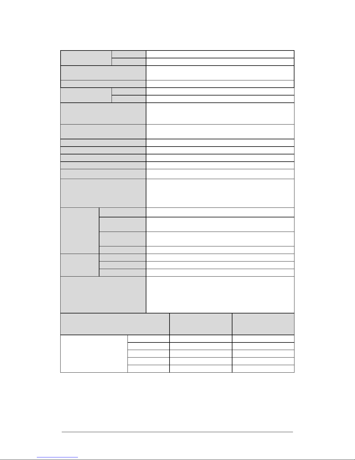
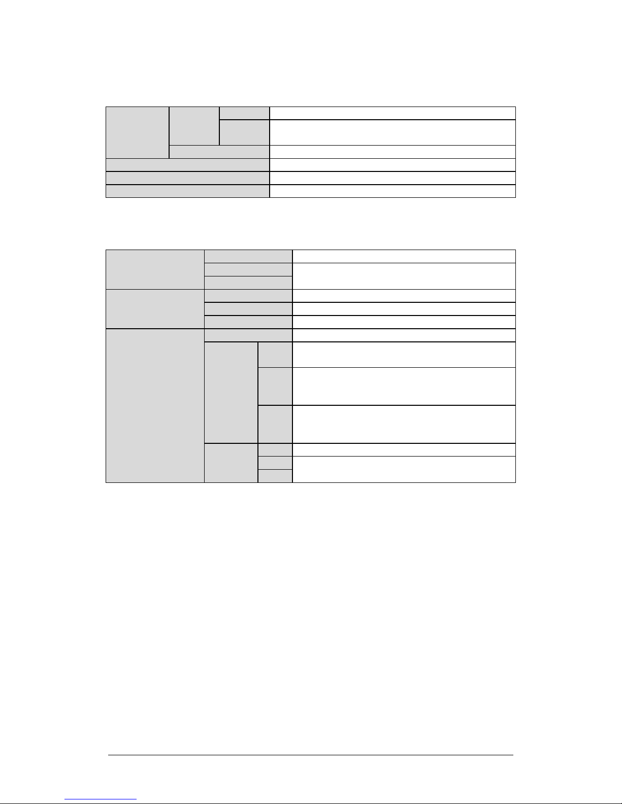
1.5 Summary of Specifications
1.5.1 Characteristics
IF Input Frequency
950 – 1525 MHz 5.850 – 6.425 GHz
950 – 1825 MHz 5.850 – 6.725 GHz (optional)
950 – 1450 MHz 14.00 – 14.50 GHz
950 – 1750 MHz
Ku-Band Units
C-Band
and/or
X-Band Units
Notes:
1. Allow 1 dB degradation from 13.75 to 14.0 GHz and 6425 to 6725 MHz.
PS1-20Ku 43 dBm (20 W) 42 dBm (16 W)
PS1-32Ku 45 dBm (32 W) 44 dBm (25 W)
PS1-40Ku 46 dBm (40 W) 45 dBm (32 W)
PS1.5-75 C,X 48.6 dBm (75 W) 48 dBm (60 W)
PS1.5-80 C,X 49 dBm (80 W) 48.5 dBm (70 W)
PS1.5-100 C,X 50 dBm (100 W) 49 dBm (80 W)
PS1.5-110 C,X 50.4 dBm (110 W) 49.5 dBm (90 W)
PS1.5-125 C,X 51 dBm (125 W) 50 dBm (100 W)
RF Output Frequency
13.75 – 14.50 GHz (optional)
1–7
Page 28
LPOD-R Outdoor Amplifier / Block Up Converter (BUC) MN-LPODR
Requirements
only)(48 VDC optional)
Max IF Input level (No Damage)
+10 dBm
+55°C))
RF Mute Isolation
-60 dBc min
In-band
Related In-band
LO Leakage
-25 dBm max
Linear
± 0.03 ns/MHz
Parabolic
±0 .003 ns/MHz2
Ripple
± 1.0 ns pk-pk
Introduction Revision 3
Gain Min (Typical)
Input Power Supply
PS .5 60 (65 dB)
PS 1, 1.5 70 (75dB)
90-264 VAC, 47-63 Hz, Power Factor Corrected, .96 (PS 1, 1.5
Gain Adjust
PS .5 10 dB in 0.25 dB steps
PS 1, 1.5 20 dB in 0.25 dB steps
±1.5 dB full band (optional ±2.0 dB full band (-50° to +55°C))
Gain Flatness
Gain Variation Over Temp
±0.40 dB per 40 MHz (optional ±0.50 dB per 40 MHz (-50° to
±1.5 dB max, -40° to +55°C (optional ±2.0 dB max (-50° to
+55°C))
Input Return Loss 14 dB (1.5:1 VSWR)
Output Return Loss 17.7 dB (1.3:1 VSWR)
Noise Figure 15 dB typical, 20 dB max @ min attenuation
AM/PM Conversion 2° typical, 3.5° max @ Rated P1dB output power
Third-order Intermodulation
Level (2 tones, @ -3 dB Total
Backoff from P1 dB (-6 dBc SCL),
-30 dBc typ., -25 dBc Guaranteed
Δ 1MHz)
Harmonics -50 dBc @ Prated – 3 dB
Spurious
Level
Carrier Related
Non-Carrier
-60 dBc min @ P1dB
-60 dBm max (Input Terminated)
Group Delay
Variation
Data Logging Parameters
Phase Noise (dBc/Hz)
(with optional internal or equivalent
performance external reference)
100 Hz -65 -62
1 KHz -75 -72
Offset
10 KHz -85 -82
100 KHz -95 -92
1 MHz -105 -102
Non-Volatile RAM: Capacity 30 days @ 90-minute intervals.
Includes:
• RF Output Power
• Mute Status
• Heatsink Temperature
Typical (C/X/Ku) dBc/Hz
Spec (C/X/Ku)
dBc/Hz
1–8
Page 29
LPOD-R Outdoor Amplifier / Block Up Converter (BUC) MN-LPODR
Standard
-40° to 131°F (-40° to 55°C)°
60°C)
Storage
-67° to 167°F (-55° to 75°C)
Humidity
100% condensing rain 2” per hour
Altitude
10,000 AMSL
Shock
Normal commercial shipping and handling
PS .5
5 lbs. (2.3 kg) Nominal
PS 1
PS1.5
PS .5
7.21 x 4.65 x 3.34 in. (183.1 x 118.1 x 84.8 mm)
Ku-Band: WR75G (8W unit), WR75 (16W unit)
Introduction Revision 3
1.5.2 Environmental
Temperature
Operating
1.5.3 Physical
Weight
Dimensions
excluding connectors
(See Section 1.6)
Connectors
PS 1 12.60 x 6.31 x 6.05 in. (320.0 x 160.3 x 153.7 mm)
PS 1.5 12.78 x 6.14 x 6.47 in. (324.6 x 155.9 x 164.3 mm)
IF/RF Input Type ‘N’ Female
RF Output
M&C
(Ethernet)
Optional
-58° to 131°F (-50° to 55°C) or -40° to 140°F (-40° to
17 lbs. (9.1 kg) Nominal
PS .5
PS 1
PS 1.5
PS .5 Weatherized RJ-45
PS 1
PS 1.5
C-Band: CPR137G
C-Band: Type ‘N’ Female (optional CPR137G)
X-Band: CPR112G
Ku-Band: WR75
C-Band: CPR137G
X-Band: CPR112G
Ku-Band: WR75
Optional 19-pin MS style (single integrated cable
assembly available, dependent upon configuration)
1–9
Page 30

LPOD-R Outdoor Amplifier / Block Up Converter (BUC) MN-LPODR
Introduction Revision 3
1–10
1.6 Dimensional Envelopes
Typical for all figures in each subsection, all dimensions are in inches. Bracketed dimensions, where shown, are in
metric units (mm). All figures depict a waveguide output unless otherwise noted.
1.6.1 LPOD-R PS .5 Dimensional Envelopes
Figure 1-4. LPOD-R PS .5 C-Band 10W Unit
Page 31

LPOD-R Outdoor Amplifier / Block Up Converter (BUC) MN-LPODR
Introduction Revision 3
1–11
Figure 1-5. LPOD-R PS .5 C-Band 20W Unit
Page 32

LPOD-R Outdoor Amplifier / Block Up Converter (BUC) MN-LPODR
Introduction Revision 3
1–12
Figure 1-6. LPOD-R PS .5 Ku-Band 8W Unit
Page 33

LPOD-R Outdoor Amplifier / Block Up Converter (BUC) MN-LPODR
Introduction Revision 3
1–13
Figure 1-7. LPOD-R PS .5 Ku-Band 16W Unit
Page 34

LPOD-R Outdoor Amplifier / Block Up Converter (BUC) MN-LPODR
Introduction Revision 3
1–14
1.6.2 LPOD-R PS 1 Dimensional Envelopes
Figure 1-8. LPOD-R PS 1 C-Band Unit – Coaxial Output
Page 35

LPOD-R Outdoor Amplifier / Block Up Converter (BUC) MN-LPODR
Introduction Revision 3
1–15
Figure 1-9. LPOD-R PS 1 C-Band Unit
Page 36

LPOD-R Outdoor Amplifier / Block Up Converter (BUC) MN-LPODR
Introduction Revision 3
1–16
Figure 1-10. LPOD-R PS 1 Ku-Band Unit
Page 37

LPOD-R Outdoor Amplifier / Block Up Converter (BUC) MN-LPODR
Introduction Revision 3
1–17
1.6.3 LPOD-R PS 1.5 Dimensional Envelopes
Figure 1-11. LPOD-R PS 1.5 C-Band Unit
Page 38

LPOD-R Outdoor Amplifier / Block Up Converter (BUC) MN-LPODR
Introduction Revision 3
1–18
Figure 1-12. LPOD-R PS 1.5 Ku-Band Unit
Page 39

Chapter 2. SYSTEM
CONNECTORS,
INSTALLATION,
STARTUP
2.1 Overview
• See Chapter 4. ETHERNET INTERFACE OPERATION for
This chapter provides user reference to the following:
• The LPOD-R connectors for signal input, signal output; monitor and
control (M&C) of the unit; and grounding of the unit to the antenna’s
grounding network;
• Available standalone installation kits;
• Instructions for installation, startup, and troubleshooting user M&C
access.
information about using the LPOD-R’s remote Ethernet M&C
functionality.
• See Chapter 5. OPTIONAL SERIAL INTERFACE OPERATION (PS 1,
PS 1.5 ONLY) for information about using the LPOD-R’s optional
serial-based remote commands and queries.
AND
2–1
Page 40

LPOD-R Outdoor Amplifier / Block Up Converter (BUC) MN-LPODR
product failure.
System Connectors, Installation, and Startup Revision 3
2.2 Water Tight Sealing
CAUTION
All external cable assemblies for the outdoor equipment MUST be
properly sealed to prevent water intrusion. Failure to achieve water
tight sealing will result in possible performance degradation and even
IMPORTANT: To maintain your product warranty, you must follow these
guidelines and recommendations during equipment installation:
• Ensure all external connections to the equipment are hand-tightened and
wrapped with a self-amalgamating tape such as 3M Type 23 Scotch SelfAmalgamating Tape (or equivalent). The sealing must cover the external
connector housing and extend beyond the end of the heatshrink that
covers the connector termination of the cable assembly.
• Squeeze the self-amalgamating tape tightly and make sure both ends of
the tape have formed around the connector and cable to create a water
tight seal.
• ALL unused external connectors MUST be covered with caps and sealed.
Make sure to inspect the connector cap rubber seal for cracks before
using.
2.2.1 Customer Cable Assemblies
CAUTION
Should you receive an accessory kit that contains only the mating cable
connectors, or if you (the end-user) choose to supply your own cables
and connectors, Comtech EF Data strongly recommends that you use
an adhesive lined heatshrink such as TE Connectivity #ATUM-24/6-0
(or equivalent) to cover the connector strain-relief area. Your sealed,
water tight cable ends should appear as per this example:
2–2
Page 41

LPOD-R Outdoor Amplifier / Block Up Converter (BUC) MN-LPODR
System Connectors, Installation, and Startup Revision 3
2.3 LPOD-R Interface Connectors
The LPOD-R external connectors provide all necessary connections between the
LPOD-R PS .5 (Figure 2-1), PS 1 (Figure 2-2), or PS 1.5 (Figure 2-3) unit and other
equipment.
Figure 2-1. LPOD-R PS .5 Connectors
Figure 2-2. LPOD-R PS 1 Connectors
Figure 2-3. LPOD-R PS 1.5 Connectors
2–3
Page 42

LPOD-R Outdoor Amplifier / Block Up Converter (BUC) MN-LPODR
Unit
Frequency / Output Type
See…
Ku-Band: WR75 (No Groove)
System Connectors, Installation, and Startup Revision 3
2.3.1 ‘J1 | LBAND IN’ Signal Input Port
The ‘J1 | LBAND IN’ RF input connector is a Type ‘N’ female
connector. Typical input levels (-30 dBm) depend on desired output
power and unit attenuation. To prevent damage to the LPOD-R, RF
input levels must not exceed +15 dBm.
2.3.2 ‘J2 | RF OUT’ Signal Output Interface
WARNING!
FOR SAFETY REASONS, NEVER LOOK DIRECTLY INTO THE WAVEGUIDE
OUTPUT.
The ‘J2 | RF OUT’ connector may be a waveguide or coaxial interface – this
depends on the LPOD-R model and/or frequency range of the unit. See Figure
2-1 through Figure 2-3 and Tab le 2-1.
Table 2-1. ‘J2 | RF O UT’ Interface Type
C-Band: CPR137G (Grooved)
PS .5
Ku-Band: WR75G (Grooved) – 8W unit
-OR- WR75 (No Groove) – 16W unit
C-Band: Type ‘N’ Female (optional CPR137G, Grooved)
PS 1
X-Band: CPR112G (Grooved)
C-Band: CPR137G (Grooved)
PS 1.5
X-Band: CPR112G (Grooved)
Ku-Band: WR75 (No Groove)
Figure 2-1
Figure 2-2
Figure 2-3
2–4
Page 43

LPOD-R Outdoor Amplifier / Block Up Converter (BUC) MN-LPODR
personal injury.
Pin
Description
B
NEUTRAL (L2)
System Connectors, Installation, and Startup Revision 3
2.3.3 ‘J3 | POWER IN’ AC Power Main (PS 1, PS 1.5 ONLY)
WARNING!
1) The LPOD PS .5 is available only as a DC unit.
2) For safety reasons, you must use the correct pin assignments.
Incorrect use of pin assignments can result in product damage or
The mating connector specification and pin assignments specific
to the LPOD-R PS 1 and PS 1.5 standard AC power interfaces are
as follows:
Mating Connector:
CEFD P/N CN/MS-STPG03F02 (ITT Cannon KPT06B-12-35)
Table 2-2. LPOD-R PS 1, PS 1.5 ‘J3 | POWER IN’ Pin Assignments
A LINE (L1)
C GND
The prime power input requirement for the LPOD-R PS 1 and PS 1.5 is as follows:
• 90-264V AC
• 47-63 Hz
The power supply is power factor corrected. The total power required from the
prime power supply depends on the model used. See Sect. 1.5 Summary of
Specifications for more information.
2–5
Page 44

LPOD-R Outdoor Amplifier / Block Up Converter (BUC) MN-LPODR
WARNING!
A
V+
C
GND
System Connectors, Installation, and Startup Revision 3
2.3.4 ‘J3 | POWER IN’ Standard or Optional DC Power
Mains
For safety reasons, make sure you know that the ‘J3 | POWER IN’ DC
power connection pin assignments are DIFFERENT for each LPOD unit.
You must use the correct pin assignments. Incorrect use of pin
assignments can result in product damage or personal injury.
For all LPOD-R models, the prime power input requirement is 38-72V DC. The
total power required from the prime power supply depends on the model in use.
See Sect. 1.5 Summary of Specifications for more information.
2.3.4.1 ‘J3 | POWER IN’ – PS .5 Standard DC Power Main
The mating connector specification and the pin assignments
specific to the LPOD-R PS .5 standard DC power interface are as
follows:
Mating Connector:
CEFD P/N CN-0020708 (SOURIAU UTS6JC8E33S)
Table 2-3. LPOD-R PS .5 ‘J3 | POWER IN’ Pin Assignments
Pin LPOD-R PS 1 Assignment
B V-
2–6
Page 45

LPOD-R Outdoor Amplifier / Block Up Converter (BUC) MN-LPODR
A
V+
C
V-
A
+48V
B
+48V
D
-48V
System Connectors, Installation, and Startup Revision 3
2.3.4.2 ‘J3 | POWER IN’ – PS 1 Optional DC Power Main
The mating connector specification and the pin assignments
specific to the LPOD-R PS 1 optional DC power interface are as
follows:
Mating Connector:
CEFD P/N CN/STPG04F01 (Glenair IPT06E-12-4-SSR-F7)
Table 2-4. LPOD-R PS 1 ‘J3 | POWER IN’ Pin Assignments
Pin LPOD-R PS 1 Assignment
B GND
D NO CONNECT
2.3.4.3 ‘J3 | POWER IN’ – PS 1.5 Optional DC Power Main
The mating connector specification and the pin assignments
specific to the LPOD-R PS 1.5 optional DC power interface are as
follows:
Mating Connector:
CEFD P/N CN-0020517
(MS3116E-14-5S(476), Amphenol PT06E-14-5S(476)).
Table 2-5. LPOD-R PS 1.5 ‘J3 | POWER IN’ Pin Assignments
Pin LPOD-R PS 1.5 Assignment
C -48V
E GND
2–7
Page 46

LPOD-R Outdoor Amplifier / Block Up Converter (BUC) MN-LPODR
See Chapter 4. ETHERNET INTERFACE OPERATION for information about
CAUTION
weatherproof installation. See Sect. 2.3.5.1 and Figure 2-4.
System Connectors, Installation, and Startup Revision 3
2.3.5 ‘J6 | COM1’ Ethernet Communications Port
using the LPOD-R’s remote Ethernet M&C functionality.
Connector Type Ref Des | Name Direction
Weatherproof RJ-45
female modular jack
(Samtec USA Corp.
P/N RPBE-01)
For permanent Ethernet connections, you MUST use the appropriate
mating connector on your supplied Ethernet cable to ensure a
This interface operates at 10/100/1000 Mbps, half and full duplex, autonegotiating.
The maximum Ethernet packet size is 1522 bytes (including Ethernet headers and
CRC).
J6 | COM 1 In/Out
2–8
Page 47

LPOD-R Outdoor Amplifier / Block Up Converter (BUC) MN-LPODR
1) Cable end is shown as assembled.
3) Be sure to maintain Item 1-to-Item 2.1 wiring as follows:
System Connectors, Installation, and Startup Revision 3
2.3.5.1 Fabricating a Weatherproof Ethernet Cable
Comtech EF Data offers two mating connector kits:
• Use CEFD P/N KT-0020707 for 5.00-5.75 mm jacket OD Ethernet cables.
• Use CEFD P/N KT-0020708 for 5.75-6.50 mm jacket OD Ethernet cables.
Do these steps to assemble a weatherproof cable (see Figure 2-4):
1. Thread the user-supplied RJ-45 CAT5e Ethernet cable (Item 1) through the
Item 2 components (Items 2.3 through 2.6). Be sure to note the order and
orientation of all kit items before final assembly of the components.
2. Crimp the RJ-45 modular plug (Item 2.1) onto Item 1. Be sure to maintain
the cable wiring per the Note 3 wiring table.
3. Snap Item 2.1 into the Ethernet Shroud (Item 2.2). Then, snap Item 2.2
into the Latched Housing (Item 2.3).
4. Slide the Sealing Gland (Item 2.4) into its seated position in Item 2.3.
5. Slide the Compression Cage (Item 2.5) onto Item 2.4.
6. Screw the Cable Nut (Item 2.6) into assembled position against Item 2.3.
(Be sure the mating surfaces of the Latched Housing and Cable Nut are
touching.) DO NOT OVERTIGHTEN.
Figure 2-4 Assembly Notes
2) Be sure to strip Item 1 to a 15mm length.
POS COLOR WIRE
01 WHITE/ORANGE
02 ORANGE
03 WHITE/GREEN
Connector End View 06 GREEN
04 BLUE
05 WHITE/BLUE
07 WHITE/BROWN
08 BROWN
TWISTING
TWISTING
TWISTING
TWISTING
2–9
Page 48

LPOD-R Outdoor Amplifier / Block Up Converter (BUC) MN-LPODR
CEFD KIT / QTY REQ’D
5.6mm OD 8-wire CAT5e
1
–
RCEF-G-01
2.1 1 1
SUB-MODP-01-8P8C-S-01
RJ-45 Modular Ethernet Plug
2.3 1 1
RCEF-B-01
Latched Housing, Nylon
Sealing Gland, Neoprene
(for 5.75-6.5mm OD Cable)
2.6 1 1
SCN-17-02
Cable Nut, Nylon
System Connectors, Installation, and Startup Revision 3
Assembly Detail Source: Samtec USA Corporation)
ITEM
2.2 1 1 RCEF-B-02 Ethernet Shroud, Nylon
2.4
2.5 1 1 NCC-17-01 Compression Cage, Nylon
KT-0020707 KT-0020708
LENGTH A/R – N/A – BY USER (not part of kit)
1
– LENGTH A/R N/A – BY USER (not part of kit)
2
– 1 RCEF-G-02
1 – SG-17-01
– 1 SG-17-02
SAMTEC PART NO. DESCRIPTION
Ethernet Cable
6.5mm OD 8-wire CAT5e
Ethernet Cable
Samtec Weatherproof Connector
Assembly (Items 2.1-2.6)
Sealing Gland, Neoprene
(for 5.0-5.75mm OD Cable)
Figure 2-4. LPOD-R Ethernet Connector Field Termination Kit Assembly
2–10
Page 49

LPOD-R Outdoor Amplifier / Block Up Converter (BUC) MN-LPODR
commands and queries.
OPERATION (PS 1, PS 1.5 ONLY).
System Connectors, Installation, and Startup Revision 3
2.3.6 ‘J6 | COM1’ Remote Communications and Discrete
Control Port (OPTIONAL)
See CHAPTER 5. OPTIONAL SERIAL INTERFACE OPERATION (PS 1, PS 1.5
ONLY ) for information about using the optional serial-based remote
Original versions of the LPOD-R PS 1 and PS 1.5 were shipped
with a discrete control connector as the primary input for
controlling and monitoring the LPOD-R. ‘J6 | COM 1’ on these
units was a 19-pin circular connector, type MS3112E14-19S. This
is now an optional configuration.
Mating connector:
MS3116J14-19P or ITT KPT06J14-19P
Table 2-6. LPOD-R ‘J6 | COM1’ (OPTIONAL) Pin Assignments
Pin Name Description
A RS485_+RX
B RS485_-RX
C RS485_+TX
D RS485_-TX
E RS232_RD Pin 3 of DB9 female connector
F Ethernet TX+ Pin 3 of RJ-45 female connector
G RS232_TD Pin 2 of DB9 female connector
H Ethernet TX- Pin 6 of RJ-45 female connector
J TX/RX Switch Drive 1 Pos Not for customer use
K GND Ground (also Pin 5 of DB-9F connector)
L SUMFLT In Open when faulted, else +5VDC
M SUMFLT Out When faulted, tied to Pin K, else open
N TX Switch Pos 1 Ind Online/Offline indication
P RX Switch Pos 1 Ind Not for customer use
R +24V Not for customer use
When AUX=1, unit is muted until this pin is tied to ground (Pin K).
S System Mute Control
When tied to ground, the unit unmutes. See the AUX remote
command in Chapter 5. OPTIONAL SERIAL INTERFACE
T Switch Common GND reference for Pin N
U Ethernet RX- Pin 2 of RJ-45 female connector
V Ethernet RX+ Pin 1 of RJ-45 female connector
2–11
Page 50

LPOD-R Outdoor Amplifier / Block Up Converter (BUC) MN-LPODR
System Connectors, Installation, and Startup Revision 3
2.3.6.1 About Circular Connectors
Circular connector pairs (Figure 2-5) feature a sleeve lock configuration, with an
array of pins (male side) coupled to mating sockets (female side).
Feature Description
1 Primary Alignment features
2 Secondary Alignment features
3 Sleeve Lock features
Figure 2-5. Circular Connector Example
Connection Instructions – Engage all of the alignment
and lock features between the male connector (on the
interconnection cable) and female socket. To install the
male connector into the female connector, do these
steps:
1. Engage the primary and secondary alignment
tabs on the male connector with the mating
cutouts on the female socket.
2. Push the male connector into the female socket.
3. Turn the male connector sleeve clockwise until
the sleeve lock cutouts engage fully with the
female socket tabs and you hear a “click” sound.
2–12
Page 51

LPOD-R Outdoor Amplifier / Block Up Converter (BUC) MN-LPODR
System Connectors, Installation, and Startup Revision 3
2.3.7 Ground Connector
Use this #10-32 stud, available where shown in Figure 2-6, to connect a
common chassis ground among equipment.
Figure 2-6. LPOD-R Ground Connector Locations
2–13
Page 52

LPOD-R Outdoor Amplifier / Block Up Converter (BUC) MN-LPODR
operation.
System Connectors, Installation, and Startup Revision 3
2.4 LPOD-R Standalone (Single-Thread) Installations
• See Section 2.2 Water Tight Sealing in this chapter for important
outdoor installation considerations.
• See Appendix A. CABLE DRAWINGS for information about the
cables that are available for use with the LPOD-R in standalone
The terms “standalone” or “single-thread” refer to applications that use a single
(1) LPOD-R unit.
Several kits are available from Comtech EF Data to mount and install standalone
LPOD-Rs, depending on the LPOD-R unit ordered:
• See Sect. 2.4.3 for standalone assembly and installation information for
pole-mounted LPOD-R configurations.
• See Sect. 2.4.4 for standalone assembly and installation for spar-mounted
LPOD-R configurations.
• See Sect.2.4.5 for standalone assembly and installation for orthomode
transducer (OMT) mounted LPOD-R configurations.
2.4.1 Installation Manpower Recommendation
Comtech EF Data recommends that, at a minimum, two technicians are
employed to install any LPOD-R PS 1 or PS 1.5 Standalone System.
2.4.2 Typical Required Installation Tools
Comtech EF Data recommends that, at a minimum, you use these tools to install
any LPOD-R Standalone System:
• Adjustable wrench;
• English and Metric unit box or socket wrenches (hex nuts and hex head
bolts are used);
• Medium Phillips screwdriver (Phillips head screws are used);
• Tin snips.
2–14
Page 53

LPOD-R Outdoor Amplifier / Block Up Converter (BUC) MN-LPODR
SECT.
NO.
Figure 2-8
System Connectors, Installation, and Startup Revision 3
2.4.3 Pole Mount Installations (PS 1, PS 1.5)
The Universal Pole Mount Kit PL/12319-1 is used in combination with polemounted standalone installation kits. For purpose of brevity, all subsequent
mention of this kit’s usage refers you back to this chapter section.
CHAPTER
CEFD PART
DESCRIPTION See…
2.4.3.1 PL/12319-1 Universal Pole Mounting Kit
2.4.3.2 KT-0000095
LPOD-R PS 1, PS 1.5 Single Unit
Mounting Kit
Figure 2-7
Figure 2-9
2–15
Page 54

LPOD-R Outdoor Amplifier / Block Up Converter (BUC) MN-LPODR
ITEM
QTY
CEFD PART NO.
DESCRIPTION
ONLY – P/O LPOD-R MOUNTING KIT)
4 2 HW/M8X1.25X25HEXSS
SS HEX HEAD BOLT, M8, 25MM LG
7 1 FP/BR0069
FLOATING STRAP BRACKET
8 1 FP/BR0071
PIPE STRAP (TRIM TO REQUIRED LENGTH)
11
1
FP/BR0072
STRAP TENSIONER BOLT
System Connectors, Installation, and Startup Revision 3
2.4.3.1 PL/12319 Universal Pole Mounting Kit
This kit accommodates a pole diameter of up to 13.00” (33.02 cm)
OD maximum.
1 1 N/A DUAL CHANNEL UNISTRUT (SHOWN FOR CLARITY
2 2 HW/M8SPRING NUT SPRING NUT, M8
3 2 HW/BLK-PIPE2-8 PIPE BLOCK
5 7 HW/M8FLATSS SS FLAT WASHER, M8
6 7 HW/M8LOCKSS SS LOCK WASHER, M8
9 5 HW/M8X1.25MMHEXNUTSS SS HEX NUT, M8
10 1 FP/BR0070 FIXED STRAP BRACKET AND STRAP
Figure 2-7. PL/12319-1 Universal Pole Mounting Kit
Use this kit in combination with a product-specific LPOD-R mounting kit to
secure the LPOD-R standalone configuration to a standard satellite dish support
pole. The number of kits used depends on the weight of the unit.
2–16
Page 55

LPOD-R Outdoor Amplifier / Block Up Converter (BUC) MN-LPODR
System Connectors, Installation, and Startup Revision 3
Do these steps to install each kit:
1. Place the Unistrut (Item 1, part of the LPOD-R Mounting Kit) on a flat
surface.
2. Slide both spring nuts (Item 2) into the Unistrut channel. Make sure to
seat the springs against the interior wall of the channel.
3. Loosely fasten the Pipe Blocks (Item 3) to the spring nuts using (2X each)
M8 hex bolts (Item 4), flat washers (Item 5), and lock washers (Item 6).
4. Position the semi-assembled Unistrut and Pipe Blocks against the
mounting pole, then slide the Pipe Blocks until they contact either side of
the mounting pole. Make sure that the Pipe Blocks are centered within
the Unistrut. Tighten the mounting hardware.
5. Slide the Floating Strap Bracket (Item 7) into the Unistrut channel. Make
sure that the bracket studs face outward.
6. Loosely assemble the Floating Strap Bracket to the Pipe Strap (Item 8)
with (2X each) M8 flat washers (Item 5), lock washers (Item 6), and hex
nuts (Item 9).
7. Do the following:
a. Holding the kit subassembly in place against the mounting pole,
slide the Fixed Strap Bracket (Item 10) into the Unistrut channel
until it abuts the adjacent Pipe Block.
b. Wrap the Pipe Strap around the pole, fitting the strap onto the
Fixed Strap Bracket studs as snugly as possible. Score or otherwise
mark a trim line on the Pipe Strap then, using the tin snips, trim
the Pipe Strap to suit as shown in the side view provided in Figure
2-8.
8. Do the following:
a. Remove the Fixed Strap Bracket (Item 10) from the Unistrut
channel, and assemble the Strap Tensioner Bolt (Item 11) to the
Fixed Strap Bracket (the bolt head will abut the interior wall of the
channel).
b. Slide this subassembly back into the Unistrut channel until it abuts
the adjacent Pipe Block.
9. Secure the Pipe Strap (Item 8) using the Fixed Strap Bracket (Item 10),
with (2X each) M8 hex nuts (Item 9), flat washers (Item 5), and lock
washers (Item 6).
10. As shown in the side view provided in Figure 2-8, secure the Fixed Strap
Bracket (Item 10) in place using the Strap Tensioner Bolt (Item 11) with
(1X each) M8 flat washer (Item5), lock washer (Item 6), and hex nut (Item
9); tighten as needed.
2–17
Page 56

LPOD-R Outdoor Amplifier / Block Up Converter (BUC) MN-LPODR
System Connectors, Installation, and Startup Revision 3
The assembled kit appears as shown in the top and side view example shown
in Figure 2-8. Depending on the application, you may proceed to the next
phase of installation.
Figure 2-8. Universal Pole Mounting Kit – Final Assembly
2–18
Page 57

LPOD-R Outdoor Amplifier / Block Up Converter (BUC) MN-LPODR
System Connectors, Installation, and Startup Revision 3
2.4.3.2 KT-0000095 Single Unit Mounting Kit (PS 1, PS 1.5)
Use this kit in combination with the PL/12319-1 Universal Pole Mounting Kit.
ITEM QTY CEFD PART NO. DESCRIPTION
1 1 FP-0000534 BRACKET, MOUNTING
2 1 FP/BR0078 UNISTRUT, DUAL CHANNEL
3 2 HW/1/4-20X1/2FH SCREW, 82° FLAT HEAD, PHILLIPS, 1/4-20 x 1/2 LG, SS
4 2 HW-0000070 SCREW, HEX, SERRATED FLANGE HEAD, 3/8-16 x 3/4 LG, SS
5 2 HW/3/8SPRINGNUT SPRINGNUT, SHORT SPRING, 3/8-16, SS (P3300)
Figure 2-9. KT-0000095 LPOD-R PS 1, PS 1.5 Single Unit Mounting Kit
2–19
Page 58

LPOD-R Outdoor Amplifier / Block Up Converter (BUC) MN-LPODR
System Connectors, Installation, and Startup Revision 3
2.4.4 Spar Mount Installation (PS 1, PS 1.5)
LPOD-R PS 1 and PS 1.5 standalone configurations, in addition to satellite dish
support pole mounted installations, may be installed on the antenna spar. Figure
2-10 shows a typical Comtech EF Data spar mount SSPA installation.
The kit that is required for the installation of your LPOD-R system (Figure 2-11) is
determined by the spar that is used by the antenna’s manufacturer.
Figure 2-10. SSPA Spar Mount Installation Example
2–20
Page 59

LPOD-R Outdoor Amplifier / Block Up Converter (BUC) MN-LPODR
BRACKET, MOUNTING,
BRACKET, MOUNTING,
1.75” x 4.0” [44.4 X 101.6] SPA R
1.0” x 2.5” [25.4 X 63.5] SPA R
System Connectors, Installation, and Startup Revision 3
CEFD KIT / QTY REQ’D
ITEM
1
2 2 2 2 2 HW/1/4-FLT FLAT WASHER, 1/4
3 2 2 2 2 HW/1/4-SPLIT LOCK WASHER, SPLIT, 1/4
4 2 2 2 2
KT-
0000083
1 – – – FP-0000547
– 1 – – FP-0000546
– – 1 – FP-0000545
– – – 1 FP-0001330
KT-
0000084
KT-
0000085
KT-
0000289
CEFD PART NO.
HW/1/4-20X11/4HEX
Figure 2-11. LPOD-R PS 1, PS 1.5 Spar Mount Installation Kits
DESCRIPTION
[dims in mm]
1.5” x 2.0” [38.1 X 50.8] SPA R
BRACKET, MOUNTING,
BRACKET, MOUNTING,
72mm x 72mm SPAR
BOLT, HEX HEAD
1/4-20 x 1-1/4” LG
2–21
Page 60

LPOD-R Outdoor Amplifier / Block Up Converter (BUC) MN-LPODR
System Connectors, Installation, and Startup Revision 3
2.4.5 KT-0020987 OMT-Mount Installation (PS .5)
Use this kit to install your LPOD-R PS .5 standalone configuration on the antenna
orthomode transducer (OMT).
ITEM QTY CEFD PA RT NO. DESCRIPTION
1 1 FP-0021719 BRACKET, LOWER
2 1 FP-0021720 BRACKET, UPPER
3 3 HW/8-SPLIT LOCK WASHER, SPLIT, #8
4 3 HW/832X5/8SHCS SOCKET HEAD CAP SCREW, 8-32 X 5/8 LG
5 2 HW/5/16-18X1.25 BOLT, HEX HEAD, 5/16-18 X 1.25 LG
6 2 HW/5/16-18HEXNT HEX NUT, 5/16-18
7 2 HW/5/16-F LT FLAT WASHER, 5/16
8 2 HW/5/16-SPLIT LOCK WASHER, SPLIT, 5/16
9 2 HW/8-32HEXNUT HEX NUT, #8-32
10 2 HW/8-FLT FLAT WASHER, #8
Figure 2-12. KT-0020987 LPOD-R PS .5 OMT-Mount Installation Kit
2–22
Page 61

LPOD-R Outdoor Amplifier / Block Up Converter (BUC) MN-LPODR
CAN BE EXPOSED TO DANGEROUSLY HIGH ELECTROMAGNETIC LEVELS.
System Connectors, Installation, and Startup Revision 3
2.5 LPOD-R Startup
2.5.1 Set the LPOD-R Power ON
WARNING!
FOR SAFETY REASONS, NEVER TURN THE UNIT ON WITHOUT PROPER
WAVEGUIDE TERMINATION ON THE ‘J2 | RF OUT’ PORT. INDIVIDUALS
The LPOD-R does not have a ‘Power On/Off’ switch. You may power ON the unit
by connecting the ‘J3 | POWER IN’ connector to the appropriate prime power
source. The Mute or Transmit status of the unit automatically comes up in the
last stored state (factory default = Transmit on, not muted).
2.5.2 Monitoring LPOD-R Operation with the LED
Indicator (PS .5 ONLY)
The LPOD-R PS .5 unit features a multi-color Light-Emitting Diode (LED) Indicator.
This LED is located on the signal output side of the LPOD-R PS .5 housing, next to
the ground lug. See Figure 2-13.
Upon power-up of the unit, this LED provides visual cues as to the operational
status and LO setting for the system. See Table 2-7 for details.
Figure 2-13. LPOD-R PS .5 LED Indicator
2–23
Page 62

LPOD-R Outdoor Amplifier / Block Up Converter (BUC) MN-LPODR
System Connectors, Installation, and Startup Revision 3
Table 2-7. LPOD-R PS .5 LED Operation
OPERATING STATUS LED COLOR UNIT STATE
Green Unmuted, 13.05 GHz LO
Standard 14.0-14.5 GHz
Uplink Frequency
Yellow Muted, 13.05 GHz LO
Red Faulted, 13.05 GHz LO
Green (blinking) Unmuted, 12.8 GHz LO
13.75-14.5 GHz Tx
Frequency Operation
Yellow (blinking) Muted, 12.8 GHz LO
Red (blinking) Faulted, 12.8 GHz LO
2.5.3 Recovering the User Interface Access
The ‘J6 | COM1’ RJ-45 Ethernet port is the only means of M&C access for the
current production version of the LPOD-R units (i.e., those models having the
weatherproof RJ-45 ‘J6 | COM1’ connector). Loss of the unit’s Management IP
Address or the interface access credentials (i.e., the username/password and
SNMP communities) prohibits M&C of the LPOD-R.
You can reset the access credentials for the LPOD-R to the factory default
settings. To do this, issue a ping command to the default Management IP Address
(169.254.1.1) within the first 10 seconds of power cycle/reset of the unit.
2.5.3.1 Recovery Steps Using a Windows PC
Do these steps:
1. Change the IP Address of the User PC NIC (the Network Interface Card
that controls the Ethernet port connected to the LPOD-R ) to
169.254.1.10:
a. On the Windows taskbar, Click ‘Start’ and then click ‘Control
Panel’.
b. From the Control Panel window, click the ‘Network and Sharing
Center’ icon.
c. Look for the ‘View your active networks’ section of the ‘Network
and Sharing Center’ window.
d. Click the ‘Local Area Connection’ hyperlink (e.g., ‘Local Area
Connection 2’) to select the targeted NIC.
e. In the ‘Interface Status’ window, click ‘Properties’.
f. If necessary, click the ‘Network’ tab.
2–24
Page 63

LPOD-R Outdoor Amplifier / Block Up Converter (BUC) MN-LPODR
System Connectors, Installation, and Startup Revision 3
g. In the ‘This connection uses the following items:’ window, select
‘Internet Protocol Version TCP/IPv4’.
IMPORTANT: Make sure that you do not uncheck the
checkbox.
h. Click ‘Properties’.
i. Enter the IP address into the address fields: 169 | 254 | 1 | 10
IMPORTANT: Make sure that you do not deselect the
‘Use the following IP address:’ radio button.
j. Click 'OK’ to save the change.
2. If you have not already done so, connect a user-supplied Ethernet cable
from the ‘J6 | COM1’ RJ-45 Ethernet port on the LPOD-R directly to the
Ethernet port of the User PC.
3. Use Windows Command-line to ping the actively running LPOD-R:
a. Type “ping -t 169.254.1.1” to begin repeatedly pinging the
LPOD-R.
b. Cycle the LPOD-R power as the User PC continues to ping the unit.
c. Continue to observe the ping responses in the Windows
Command-line window.
4. Wait for one successful ping reply, followed by an unsuccessful ping –
once the LPOD-R receives a ping on IP address 169.254.1.1 within the first
10 seconds of the unit’s power-up or reset, it restores the interface access
factory default values:
• DEFAULT MANAGEMENT IP ADDRESS/RANGE – 192.168.1.4/24
• DEFAULT HTTP INTERFACE USERNAME – comtech
• DEFAULT HTTP INTERFACE PASSWORD – comtech
5. As per Step 1, change the IP address of the User PC’s assigned Ethernet
port to an address within the 192.168.1.XXX subnet (i.e., assign a
Management IP Address to the LPOD-R from 192.168.1.001 through
192.168.1.255).
The LPOD-R management interface is now accessible and ready for M&C of the
unit.
2–25
Page 64

LPOD-R Outdoor Amplifier / Block Up Converter (BUC) MN-LPODR
System Connectors, Installation, and Startup Revision 3
Notes:
2–26
Page 65

Chapter 3. FIRMWARE
The original versions of the LPOD-R PS 1 and PS 1.5 were
UPDATE
3.1 Firmware Overview
Make sure to operate the LPOD-R with its latest available firmware.
Comtech EF Data’s LPOD-R family of Outdoor Amplifiers / Block Up Converters
(BUCs) are factory-shipped with the latest version of operating firmware. If you
need to update the firmware, you can apply the update to the LPOD-R without
having to remove it from operation. You may directly acquire the download from
Comtech EF Data’s web site (www.comtechefdata.com), or receive the archive
file by e-mail from Comtech EF Data Product Support.
3.1.1 LPOD-R Firmware Update Procedure Summary
1. Download the firmware update archive file to a user-supplied PC. The PC
must be Microsoft Windows® compatible. Comtech EF Data’s opti o nal
LPODnet is available for Ethernet-based remote monitor and control
(M&C) of the LPOD-R.
2. Connect a user-supplied Ethernet cable from the User PC to the ‘J6 |
COM1’ RJ-45 Ethernet port.
shipped with a 19-pin ‘J6 | COM1’ port. This allowed use of
Comtech EF Data’s optional CLC-10 Handheld Terminal M&C
Accessory Kit (CEFD Kit KT-0020518) for optional serial-based
M&C of the LPOD-R PS 1 or PS 1.5.
3–1
Page 66

LPOD-R Outdoor Amplifier / Block Up Converter (BUC) MN-LPODR
Firmware Update Revision 3
3. Extract the firmware update files from the archive download file. You may
then use Comtech’s “CReflash” utility. (This utility is only provided in the
LPOD-R PS .5 firmware archive download, but it may also be used for the
PS1 and PS1.5 firmware update procedures.) Otherwise, you must use the
LPOD-R Management IP Address to connect the FTP client to an FTP
server, and then FTP-transfer the files from the User PC to the LPOD-R.
3.1.2 About Firmware Numbers, File Versions, and
Formats
The Comtech EF Data Web site catalogues its firmware update archive
files by product type (e.g., router, modem, etc.), the specific model, and
optional hardware configurations. The LPOD-R files are provided under
“Home | Support | Software Downloads | Amplifier Software
Downloads | LPOD-R Software Downloads”:
• The LPOD-R PS .5 firmware download hyperlink appears as
F0020841x_V###.
• The LPOD-R PS 1 and PS 1.5 firmware download hyperlink
appears as F0020880x_V###.
Typical for either hyperlink, ‘x’ is the firmware revision letter, and ‘###’
represents the firmware version number (e.g., V123 = Version 1.2.3).
Comtech EF Data provides its archive download files in two compressed
formats – *.exe (self-extracting) and *.zip (compressed):
• The self-extracting *.exe file does not require use of a third-
party utility program.
• Some firewalls do not allow the download of self-extracting
*.exe files. You must instead download the *.zip file, and extract
the firmware files from the download with a user-supplied
third-party file archiver and compression utility program such as
PKZIP for Windows, WinZip, ZipCentral, etc. (PKZIP for DOS is
not supported due to file naming conventions). Comtech EF
Data does not provide this utility program.
For detailed information on handling archived files, read your utility
program’s Help documentation.
3–2
Page 67

LPOD-R Outdoor Amplifier / Block Up Converter (BUC) MN-LPODR
Firmware Update Revision 3
3.2 Prepare for the Firmware Download
3.2.1 Required User-supplied Items
You will need a Microsoft Windows-based PC equipped with available serial and
Ethernet ports, a compatible Web browser (e.g., Internet Explorer), and a
terminal emulator program (e.g., Tera Term or HyperTerminal).
3.2.1.1 LPOD-R Connections for All Current Production Units
Figure 3-1. M&C Utilities Available from Comtech EF Data (All Current
LPOD-R Models)
See Figure 3-1:
You can use Comtech’s optional LPODnet (part of CEFD KT-0000203 M&C
Netbook Accessory Kit) for Ethernet-based M&C of the LPOD-R. The LPOD-R
features a weatherproof ‘J6 | COM1’ RJ-45 modular port for the M&C interface.
Use a CAT5e Ethernet cable to connect the LPOD-R directly to the Ethernet port
of the User PC.
CAUTION
For permanent Ethernet connections, you MUST use the appropriate
mating connector on your supplied Ethernet cable to ensure a
weatherproof installation. You may fabricate this cable using CEFD
connector kit KT-0020707 or KT-0020708. See Figure 3-1, and Section
2.2.5.1 and Figure 2-4 in Chapter 2 for details.
3–3
Page 68

LPOD-R Outdoor Amplifier / Block Up Converter (BUC) MN-LPODR
Firmware Update Revision 3
3.2.1.2 LPOD-R Connections for Earlier PS 1 or PS 1.5 Units
If you are using a user-supplied terminal emulator program – you can use a userfabricated 9 pin-to-19 pin adapter cable to directly connect the PC serial port to
the LPOD-R PS 1 or PS 1.5 19-pin ‘J6 | COM1’ port.
Figure 3-2. M&C Utilities Available from Comtech EF Data (Earlier
LPOD-R PS1 or PS 1.5 Models)
See Figure 3-2:
• You can u se Comtech EF Data’s optional CLC-10 Handheld Terminal (part
of CEFD M&C Accessory Kit KT-0020518) for serial-based monitor and
control of the LPOD-R PS 1 or PS 1.5 (when the optional EIA-232/485
serial interface is available).
This kit provides an adapter cable (CEFD P/N CA-0020526) to connect the
CLC-10 to the LPOD-R PS 1 or PS 1.5 19-pin ‘J6 | COM1’ port.
The CLC-10 is not supported for use with the current LPOD-R
production models.
3–4
Page 69

LPOD-R Outdoor Amplifier / Block Up Converter (BUC) MN-LPODR
originally shipped with the 19-pin ‘J6 | COM1’ 19-pin port.
Firmware Update Revision 3
• Use the 19 pin-to-RJ-45 adapter cable (CEFD P/N CA-0000352) that is part
of the KT-0000203 LPODnet Netbook Accessory Kit to connect the
LPODnet or the User PC to the LPOD-R PS 1 or PS 1.5 19-pin ‘J6 | COM1’
port.
3.2.2 Configure the Terminal Emulator Program
On the User PC – Open the terminal emulator program, and then configure the
program’s serial port communication and terminal display operation:
• Baud Rate = 38400 bps
• Data Bits = 8
• Stop bits = 1
• Parity = NO
• Local Echo = ON
• Port Flow Control = NONE
• Display New Line Rx/Tx = CR
1) Read your terminal emulator program user guide or HELP feature
for operating and configuration instructions.
2) The CLC-10 Handheld Terminal may be used in place of a PC-based
Terminal Emulator for LPOD-R PS 1 or PS 1.5 units that were
3.2.3 Get the LPOD-R Management IP Address and
Firmware Information
1. On the LPOD-R – Apply power to the unit. Your power connection varies
depending on your ordered unit.
See Section 2.2.3 or Section 2.2.4 in Chapter 2. SYSTEM
CONNECTORS, INSTALLATION, AND STARTUP in this manual to
identify your specific power connector.
2. Identify your default Management IP Address. You will not be able to
access the LPOD-R HTTP Interface without this information.
3–5
Page 70

LPOD-R Outdoor Amplifier / Block Up Converter (BUC) MN-LPODR
If needed, see Section 2.4.3 in Chapter 2. SYSTEM
Firmware Update Revision 3
CONNECTORS, INSTALLATION, AND STARTUP in this manual to
execute the LPOD-R User Interface Access recovery procedure.
3. Get the firmware information using either of these methods:
• To use the HTTP (Web Server) Interface, see Section 3.2.3.1.
• To use the optional serial remote control, see Section 3.2.3.2.
3.2.3.1 Use the HTTP Interface to Find the Firmware Information
Chapter 4. ETHERNET INTERFACE OPERATION
Do these steps:
1. Go to one of these pages to review the firmware information:
• The ‘Firmware Information’ section of the ‘Config | Utility’ page
provides the firmware details as Boot, Bulk1, and Bulk2, as shown
in this example:
• The ‘Summary’ section of the ‘Status | Summary’ page provides
the firmware details as “FW Revision”, “Active Software Image”,
and “Next Reboot Image”, as shown in this example:
2. Write down your firmware information for further reference or to provide
to Comtech EF Data Product support.
3–6
Page 71

LPOD-R Outdoor Amplifier / Block Up Converter (BUC) MN-LPODR
Firmware Update Revision 3
3.2.3.2 Use the Optional Serial Interface to Find the Firmware
Information
Chapter 5. OPTIONAL SERIAL INTERFACE OPERATION (PS 1, PS 1.5
ONLY )
Use your terminal emulator program or CLC-10 to execute remote queries with
the LPOD-R. Use either of these remote queries to find the firmware information:
• Condensed : <0/SWR?[cr]
(returns the firmware version numbers running under Boot, Bulk1,
and Bulk2, in the form B.B.BB)
• Detailed : <0/FRW?[cr]
(returns the complete information of the firmwares running under
Boot, Bulk1, and Bulk2 in the form FW-AAAAAAA B.B.BB DD/MM/YY,
where:
• FW-AAAAAAA = the firmware part number
• B.B.BB = the firmware version number
• DD/MM/YY = the firmware release date (Day/Month/Year)
3.2.4 Make a Temporary Folder (Subdirectory) on the
User PC
The temporary folder is where you store the firmware archive download. There
are several ways you can make a temporary folder on a Windows PC:
• To use the Windows Desktop, see Section 3.2.4.1.
• To use Windows Explorer, see Section 3.2.4.2.
• To use the Run and Browse windows, see Section 3.2.4.3.
• To use Windows Command-line or the Command Prompt, see Section
3.2.4.4.
1) These examples specify drive letter “c:”. You can use any valid,
After you make the temporary folder, proceed to Section 3.3 to download and
extract the firmware files.
writable drive letter.
2) Typical for many of the tasks that follow, type the command as
instructed and then press Enter.
3–7
Page 72

LPOD-R Outdoor Amplifier / Block Up Converter (BUC) MN-LPODR
Firmware Update Revision 3
3.2.4.1 Use Windows Desktop to Make a Folder
Do these steps:
1. Right-click anywhere on the desktop to open the popup submenu.
2. Select New > Folder to make the new, temporary folder on the desktop.
3. Right-click on the new folder and then select Rename from the popup
submenu. Rename this folder to “temp” or some other convenient,
unused name.
3.2.4.2 Use Windows Explorer to Make a Folder
Do these steps:
1. Left-double-click the Windows Explorer icon on the Windows Desktop.
2. Depending in your Windows OS version: select File > New > Folder, or
click your Folder Destination (e.g., Windows (C:) and then New Folder to
make the new, temporary folder in the active location.
3. Right-click the New Folder folder name, and then Rename this folder to
“temp” or some other convenient, unused name.
3–8
Page 73

LPOD-R Outdoor Amplifier / Block Up Converter (BUC) MN-LPODR
Firmware Update Revision 3
3.2.4.3 Use the Run and Browse Windows to Make a Folder
Select Start on the Windows taskbar and then do these steps:
1. Click Run… to open the Run window.
2. Click Browse… to open the Browse window.
3. Click New Folder. This can be an icon or a text label, depending on the
Windows OS version.
4. Right-click the New Folder folder name, and then Rename this folder to
“temp” or some other convenient, unused name.
3.2.4.4 Use Windows Command-line or Command Prompt to
Make a Folder
Select Start on the Windows taskbar and then do these steps:
1. Click Run... to open the Run window (o r, depending on Windows OS
version prior to Windows 95, click the MS-DOS Prompt icon from the
Main Menu).
2. Open a Command-line window:
• For Windows 95 or Windows 98 – type “command”.
• For any Windows OS versions later than Windows 98 – type “cmd” or
“command”.
• Alternately, from Start, select the All Programs > Accessories popup
submenu, and then select Command Prompt:
3–9
Page 74

LPOD-R Outdoor Amplifier / Block Up Converter (BUC) MN-LPODR
Firmware Update Revision 3
3. From the c:\> prompt, type either “mkdir temp” or “md temp” (both
“mkdir” and “md” mean “make directory”), and then press Enter.
There will now be a “temp” folder created and available for placement of the
firmware file download.
3.3 Download and Extract the Firmware Update
Files
Do these steps:
1. Go online to www.comtechefdata.com.
2. On the Main page – Under Support Information or the Support tab,
select the Software Downloads hyperlink.
3. On the Software Downloads page – Click Download Flash and Software
Update Files.
4. On the Flash Updates Index page – Select the (Select a Product Line)
Amplifiers hyperlink.
5. On the Amplifiers product page – Select the LPOD-R product hyperlink;
6. Select the appropriate firmware archive EXE or ZIP file download
hyperlink.
7. Once you select the EXE or ZIP hyperlink, the File Download dialogue
opens on your browser and prompts an action. You may otherwise click
[Cancel] to quit the file download process. Note the following:
• For EXE files:
3–10
Page 75

LPOD-R Outdoor Amplifier / Block Up Converter (BUC) MN-LPODR
Firmware Update Revision 3
o Click [Run] to open the self-extractor dialogue window. Use
[Browse] to select your destination folder. Click [Unzip] to
extract the files. Your results display as per this example –
click[OK] to close. Your files are now available for transfer to
the LPOD-R.
o Click [Save] to download the EXE file to your Downloads
folder. Once the download is complete the dialogue prompts
you to either [Run] the self-extracting file, or to open or view
the Windows Downloads folder for further action.
• For ZIP files:
o Click [Open] to open the archive file. Use the WinZip features
to select the files for extraction to your destination folder.
o Click [Save] to download the ZIP file to your Windows
Downloads folder. Once the download is complete the
dialogue prompts you to either [Open] the archive file, or to
3–11
Page 76

LPOD-R Outdoor Amplifier / Block Up Converter (BUC) MN-LPODR
Firmware Update Revision 3
open or view the Windows Downloads folder for further
action.
8. If not already done with File Download > Open, you must extract, at a
minimum, these files (filenames are subject to change):
• FOR THE LPOD-R PS .5:
o FW-0020841X_###.bin – The Firmware Bulk image file
o ReleaseNotes_ FW-0020841x_v#_#_#.pdf – The Firmware
Release Notes PDF file
o CReflash.exe –The Firmware Update Utility program
• FOR THE LPOD-R PS 1 OR PS 1.5:
o FW-0020880X_V###.bin – The Firmware Bulk image file
o ReleaseNotes_FW-0020880X_V###.pdf – The Firmware
Release Notes PDF file
WHERE: ‘X’ is the firmware revision letter, and ‘#_#_#’ or
‘###’ is the firmware version (e.g., FW Ver. 1.2.3 = “1_2_3”
or “123”)
9. Confirm availability of the firmware files in the temporary folder. There
are several ways you can view the contents of the temporary folder on a
Windows-based PC:
• To use the Windows Desktop, see Section 3.3.1.1.
• To use Windows Command-line or Command Prompt, see Section
3.3.1.2.
After you confirm the firmware files are in the folder, proceed to Section
3.4 to upload the firmware update to the LPOD-R.
3.3.1.1 Use Windows Desktop to View Folder Contents
From the Windows Desktop:
1. Double-left-click the Windows Explorer icon, and then double-left-click as
needed to locate, and then open, the “temp” folder (directory) created
earlier on the Windows Desktop.
2. Use the Browse window (Start > ...Run > Browse) to locate, and then
double-click to open, the “temp” fo ld er.
3–12
Page 77

LPOD-R Outdoor Amplifier / Block Up Converter (BUC) MN-LPODR
Firmware Update Revision 3
3.3.1.2 Use Windows Command-line to View Folder Contents
Using Command-line or Command Prompt:
1. Type “cd c:\temp” at the Windows Command-line prompt to change to
the temporary folder (directory) created earlier using Command-line.
2. Type “dir” to list the files extracted to the temporary folder from the
downloaded archive file.
3.4 Upload the Firmware Files and Update the
LPOD-R Unit
3.4.1 Important Considerations
Before you proceed with the firmware update, make sure that:
• You connect the LPOD-R ‘J6 | COM1’ port to a Windows-based PC
Ethernet port with a CAT5e Ethernet cable.
• Your PC is running a terminal emulation program for operation of the
LPOD-R Ethernet Telnet or the optional serial interfaces.
• You have noted your LPOD-R Management IP Address.
• Your PC is running a compatible Web browser for operation of the LPOD-R
HTTP Interface.
• You download or otherwise have Comtech’s latest firmware files and the
“CReflash” utility available on the User PC in an accessible temporary
fo ld e r.
3.4.2 Steps to “CReflash” Upload the Firmware Files (All
LPOD-R Models)
The “CReflash” utility is provided with the LPD-R PS .5 firmware
download. This application may also be used for the LPOD-R PS 1 or PS
1.5 firmware update procedures.
Do these steps:
1. From the temporary folder – Locate, and then double-click, the
“CReflash” filename or icon. The CReflash utility opens:
3–13
Page 78

LPOD-R Outdoor Amplifier / Block Up Converter (BUC) MN-LPODR
1) Typical for all steps: “xxx.xxx.xxx.xxx” represents the assigned unit
2) Type all commands without quotes, and press Enter to execute.
Firmware Update Revision 3
2. Enter your upload parameters information into CReflash:
a. Left-click in the “IP Address:” text box, and enter the default
Management IP Address (e.g., 192.168.1.4).
b. Left-click in the “Local Filename:” text box. Then, click [Browse]
and navigate to the temporary folder created earlier. Click on the
firmware “BIN” filename, and then click [Open]. The filename will
appear in the “Local Filename:” text box.
c. Make sure the drop-down list remains set to “bulk:”.
d. Click [Start] to begin the upload process. If the information was
correctly entered into CReflash, the utility displays an animated
progress bar at the bottom of the window, along with a series of
messages:
• “Opening FTP”
• “Sending data file to modem:”
• “Writing FLASH: # of #”
• “Success!”
3. When done, click [Cancel] to exit CReflash.
3.4.3 Steps to FTP Upload the Firmware Files
1. To proceed, you should already have noted the Management IP Address for
the LPOD-R as instructed in Section 3.2.3.
2. Use Windows Command-line to send a ping command. To ping the unit, type
“ping xxx.xxx.xxx.xxx” at the Windows Command-line prompt. The response
should confirm whether the unit is connected and communicating correctly
with the User PC.
Management IP Address.
3–14
Page 79

LPOD-R Outdoor Amplifier / Block Up Converter (BUC) MN-LPODR
Firmware Update Revision 3
3. Use Windows Command-line to transfer the files from the User PC to the
LPOD-R unit via FTP:
a. Type “ftp xxx.xxx.xxx.xxx” to open the FTP session.
b. Type “bin” to set the binary transfer mode.
c. Type “prompt”.
d. Type “hash”.
e. To begin the file transfer:
• For the LPOD-R PS .5 only, type “put FW-0020841X.bin a:\bulk.bin:”
or
• For the LPOD-R PS 1 or 1.5, type “put FW-0020880X.bin a:\bulk.bin:”
The destination “a:\bulk.bin:” must be all lower-case.
Wait for the file transfer to end.
f. Type “bye” to close the FTP session.
g. Close the Windows Command-line window.
4. To verify that the PC-to-unit FTP file transfer was successful, find the current
firmware information via the HTTP or optional serial interfaces (see Sections
3.3.1.1 or 3.3.1.2).
3.4.4 Steps to Update the LPOD-R Unit
Chapter 4. ETHERNET INTERFACE OPERATION
Use the LPOD-R HTTP Interface to select the new firmware and soft-reboot the
unit. Go to the ‘Config | Utility’ page and do these steps:
1. Select the preferred Current Active Firmware Image:
a. Use the ‘Next Reboot Image’ drop-down list to select Image 1 or 2.
b. Click [Submit].
2. Soft-reboot the LPOD-R:
a. In the ‘Perform Soft Reboot’ section, click [Reboot Now].
b. Wait while the LPOD-R reboots with the Current Active Firmware Image.
3. To load a second image, repeat Steps 1 and 2.
3–15
Page 80

LPOD-R Outdoor Amplifier / Block Up Converter (BUC) MN-LPODR
Firmware Update Revision 3
4. After the unit has rebooted with the new firmware, if the optional serial
interface is available you may clear the trending data. Use the terminal
emulator or CLC-10 Handheld Terminal to enter serial remote command
<0/CTD=1[cr].
The LPOD-R is now operating with its latest firmware. The firmware update
process is complete.
3–16
Page 81

Chapter 4. ETHERNET
Monitor and Control (M&C) of the LPOD-R.
INTERFACE OPE RATION
4.1 Overview
Ethernet remote monitor and control (M&C) of the LPOD-R is available through
its 100BaseT/10BaseTx Ethernet Management Interface by connecting the User
PC Ethernet port to the ‘J6 | COM1’ RJ-45 port on the LPOD-R.
Three protocols are available to use for Ethernet remote M&C. Operate these
protocols separately.
• Simple Network Management Protocol (SNMP). This requires a user-
supplied Network Monitoring System (NMS) and a user-supplied
Management Information Base (MIB) File Browser.
CAUTION
Comtech EF Data recommends use of the Ethernet-based SNMP
interface for advanced users only. All other users are strongly
encouraged to use the LPOD-R HTTP Interface for remote
• Telnet Interface. When the optional EIA-232/485 serial interface is
available, you may use the serial remote control protocol via this
interface. This requires use of the User PC’s Command line interface, or a
user-supplied terminal emulation program, such as HyperTerminal.
• HTTP (Web Server) Interface. This requires a compatible user-supplied
web browser such as Internet Explorer.
4.1.1 Prerequisites
Before you proceed with Ethernet remote product management, make sure the
following is true:
4–1
Page 82

LPOD-R Outdoor Amplifier / Block Up Converter MN-LPODR
Ethernet Interface Operation Revision 3
• The LPOD-R is operating with the latest version firmware files.
• The User PC is running a terminal emulation program for operation of the
LPOD-R Telnet Interface.
• The User PC is running a compatible web browser for operation of the
LPOD-R HTTP Interface.
• The user-supplied Windows PC is connected to the LPOD-R as applicable:
o The ‘J6 | COM1’ port on the unit connects to the User PC Ethernet
port with a user-provided Ethernet cable that has the available
weatherproof connector kit (CEFD P/N KT-0020707 or KT-
0020708).
o Older versions of the LPOD-R PS 1 and PS 1.5 feature a 19-pin ‘J6 |
COM1’ port. The unit connects to the User PC Ethernet port with
the available CA-0000352 Ethernet Interface Cable (part of CEFD
Kit KT-0000203).
• You have recorded the LPOD-R’s Management IP Address.
4.2 SNMP Interface
SNMP is an Internet-standard protocol for managing devices over IP networks. An
SNMP-managed network has three key components:
• The managed device. This includes the LPOD-R.
• The SNMP Agent. This software runs on the LPOD-R. The LPOD-R SNMP
Agent supports both SNMPv1 and SNMPv2c.
• The user-supplied Network Management System (NMS). This software
runs on the User PC.
4.2.1 Management Information Base (MIB) Files
An MIB file is used for SNMP remote management of a unique device, and
consist of a tree of nodes called Object Identifiers (OIDs). Each OID provides
remote management of a particular function. These MIB files should be compiled
in a user-supplied MIB Browser or SNMP Network Monitoring System server.
In these LPOD-R MIB file names, the letter x represents the revision of the file.
4–2
Page 83

LPOD-R Outdoor Amplifier / Block Up Converter MN-LPODR
Ethernet Interface Operation Revision 3
4.2.1.1 ComtechEFData Root MIB file
• FW-0000291x.mib
• ComtechEFData MIB file gives the root tree for all Comtech EF Data
LPOD-R products (PSx) and consists of only the following OID:
o Name: comtechEFData
o Type: MODULE-IDENTITY
o OID: 1.3.6.1.4.1.6247
o Full path:
iso(1).org(3).dod(6).internet(1).private(4).enterprises(1).comtechEFD
ata(6247) Module: ComtechEFData
4.2.1.2 LPOD-R MIB file
• FW-0000289x.mib
• MIB file consists of all of the OID’s for management of the LPOD-R
functions
4.2.1.3 LPOD-R Traps MIB file
• FW-0000290x.mib
• Trap MIB file provides SNMPv1 traps common for LPOD-R.
4.2.2 SNMP Community Strings
CAUTION
In SNMP v1/v2c, the SNMP Community String is sent unencrypted in the
SNMP packets. Caution must be taken by the network administrator to
ensure that SNMP packets travel only over a secure and private network
if security is a concern.
The LPOD-R uses Community Strings as a password scheme that provides
authentication before gaining access to the router agent’s MIBs. They are used
to authenticate users and determine access privileges to the SNMP agent. The
LPOD-R defines three Community Strings for SNMP access:
• Read Community default = public
• Write Community default = private
• Trap Community default = comtech
Type the SNMP Community String into the user-supplied MIB Browser or
Network Node Management software.
4–3
Page 84

LPOD-R Outdoor Amplifier / Block Up Converter MN-LPODR
For correct SNMP operation, the LPOD-R MIB files must be used with the
Notes for information on the required FW/SW compatibility.
Ethernet Interface Operation Revision 3
associated version of the LPOD-R M&C. See the LPOD-R FW Release
4.3 Telnet Interface
Chapter 5. OPTIONAL SERIAL INTERFACE OPERATION (PS 1, PS
1.5 ONLY)
The LPOD-R has a Telnet interface for the purpose of equipment M&C via the
optional Serial Remote Control protocol. The Telnet interface requires user login
at the Administrator level and Read/Write level. Once logged into the Telnet
interface as the Administrator, you have access to the optional serial-based
Remote Control Interface. An example of the login process and remote control
operation is shown here:
Figure 4-1. Telnet Interface Example – Windows Command-line
4.3.1 Using HyperTerminal for Telnet Remote Control Operation
There is a disadvantage when using Windows Command line as a Telnet client
with the optional Remote Control protocol. For the messages coming from the
Telnet Server, Command line cannot translate a carriage return command (\r) to
a carriage return + line feed command (\r\n). Therefore, any multi-line Targetto-Controller response (e.g., the response to the FRW? query) shows as one line,
with the latter lines overwriting the previous lines.
4–4
Page 85

LPOD-R Outdoor Amplifier / Block Up Converter MN-LPODR
Ethernet Interface Operation Revision 3
To see the full response messages, you can use the HyperTerminal terminal
emulation program configured as a Telnet client. An example of the login process
and remote control operation, when using HyperTerminal as the interface, is
shown here:
Figure 4-2. Telnet Interface Example – HyperTerminal
4.3.1.1 Configure HyperTerminal for Telnet Remote Control
Operation
Figure 4-3. Configure HyperTerminal
See Figure 4-3. Do these steps:
4–5
Page 86

LPOD-R Outdoor Amplifier / Block Up Converter MN-LPODR
Ethernet Interface Operation Revision 3
1. Make sure to define the Connect To Telnet connection properties
correctly (File Properties)(Figure 4-3, left):
a. Enter the LPOD-R’s Traffic/Management IP Address as the “Host
address” (e.g., 192.168.1.1).
b. Enter TCP Port 23
as the “Port number”.
c. Set “Connect using” to TCP/IP (Winsock) instead of COM1 or
COM2.
d. Click [OK] to save your settings.
2. For ASCII Setup (File Properties Settings ASCII Setup)(Figure 4-3,
right):
a. Check the “Send line ends with line feeds” option in the ‘ASCII
Sending’ section.
b. Check the “Append line feeds to incoming line ends” option in
the ‘ASCII Receiving’ section.
c. Click [OK] to save your settings.
4.4 HTTP (Web Server) Interface
A user-supplied web browser allows the full M&C of the LPOD-R through its HTTP
Interface. This embedded web application is designed for use with Microsoft’s
Internet Explorer Version 5.5 or higher. It is a non-secure web application.
4.4.1 Set Up Access to the HTTP Interface
Do these steps to set up access the HTTP Interface:
1. Use Windows Command-line: Select Start, then Run, then type cmd.
2. Click OK to open the Command-line window.
3. Start a Telnet session with the unit at the default IP Address (e.g.,
192.168.1.4).
4. Enter the username and password. The default for both parameters is
“comtech”.
4–6
Page 87

LPOD-R Outdoor Amplifier / Block Up Converter MN-LPODR
Ethernet Interface Operation Revision 3
5. Use the command IPA=xxx.xxx.xxx.xxx.yy, where “xxx.xxx.xxx.xxx” is a
valid IP Address on the network where the unit is to be installed, and “yy”
is the subnet range (typically, yy = 24).
1) You must assign a unique IP Address for each unit on the network
before connecting to an existing network. The IP Address may need
to be changed from the factory default setting.
2) Changing the IPA value requires that you cycle power on the unit,
and then start a new Telnet session using the new IP Address.
3) Loss of the unit’s Management IP Address or the interface access
credentials (i.e., the username/password and SNMP communities)
prohibits M&C of the LPOD-R. Follow the procedures described in
Sect. 2.4.3 Recovering the User Interface Access (in Chapter 2.
SYSTEM CONNECTORS, INSTALLATION, AND STARTUP) to restore the
factory default M&C interface access settings.
See the table of Remote Commands and Queries in Chapter 5. OPTIONAL
SERIAL INTERFACE OPERATION (PS 1, PS 1.5 ONLY) for detailed
operational information.
4.4.2 HTTP Interface User Login
Do these steps:
1. From the PC, enter the default IP Address for the LPOD-R (e.g.,
http://192.168.1.4) into the Address area of the browser.
2. In the Login window, type the User name and Password, and then click
OK. The default User Name and Password are both comtech.
4–7
Page 88

LPOD-R Outdoor Amplifier / Block Up Converter MN-LPODR
Ethernet Interface Operation Revision 3
Once the valid User Name and Password is accepted, the LPOD-R HTTP
Interface splash page shows (Figure 4-4). The unit and firmware version
in this example will differ from your setup.
Figure 4-4. LPOD-R HTTP Interface “Splash” Page (PS .5 Unit
Example Shown)
4.4.3 HTTP Interface Features
4.4.3.1 Menu Tree
Figure 4-5 shows the menus and pages in the LPOD-R HTTP Interface. This
interface has four top level navigation tabs, shown in blue. Each top level tab has
page hyperlinks (grey). These hyperlinks open individual nested Web pages.
Home Admin Config Status
Home Access Amplifier Summary
Contact SNMP Utility Status
Support MOP
Events
Statistics
Trending Graphs
Figure 4-5. LPOD-R HTTP Interface Menu Tree
4–8
Page 89

LPOD-R Outdoor Amplifier / Block Up Converter MN-LPODR
first clicking the action button, your changes are not saved.
Ethernet Interface Operation Revision 3
4.4.3.2 Page Navigation
The HTTP Interface has four navigation tabs at the top of
each page. Click a navigation tab to see its page
hyperlinks. Click a page hyperlink to open a page.
This manual uses a convention for all web pages to show you how to navigate to
the featured page: Navigation Tab | Page Hyperlink.
For example, “Home | Home” instructs you to click the ‘Home’ navigation tab,
and then click the ‘Home’ page hyperlink.
4.4.3.3 Page Sections
Each page has one or more sections. The title at the
upper-left corner of each page or section describes its
operational features. Each section can have editable
fields, action buttons and read-only displays for a
specific function.
This manual explains the purpose and operation for each Web page and its
sections.
4.4.3.4 Action Buttons
Action buttons are important in the LPOD-R HTTP Interface.
Click an action button to do one of these tasks:
• Refresh the page to see the latest data.
• Reset changed parameters to remove unsaved changes.
• Submit (save) changes.
If you change any parameters, make sure to click the related action
button before you leave the page. If you go to another page without
4.4.3.5 Drop-down Lists
A drop-down list lets you choose from a list of selections.
Left-click the drop-down button to open the list. Then, leftclick on an item to select that choice.
4–9
Page 90

LPOD-R Outdoor Amplifier / Block Up Converter MN-LPODR
Ethernet Interface Operation Revision 3
4.4.3.6 Text or Data Entry
Text boxes let you type data into a field. An action
button can be associated with a single text box, or a
group of text boxes. For any text box, left-click anywhere
inside the box and type the desired data into that field.
Make sure to press ENTER when done typing.
Click the related action button to save the data.
4–10
Page 91

LPOD-R Outdoor Amplifier / Block Up Converter MN-LPODR
Ethernet Interface Operation Revision 3
4.5 HTTP Interface Page Examples and Descriptions
4.5.1 Home Pages
4.5.1.1 Home | Home
Use this page to identify the product. Click the Home navigation tab or the page
hyperlink to return to this page from anywhere in the HTTP Interface.
Figure 4-6. LPOD-R Home Page (PS .5 Unit Example Shown)
4.5.1.2 Home | Contact / Home | Support pages
For all product support, please call:
+1.240.243.1880
+1.866.472.3963 (toll free USA)
4–11
Page 92

LPOD-R Outdoor Amplifier / Block Up Converter MN-LPODR
Ethernet Interface Operation Revision 3
4.5.2 Admin Pages
The Admin pages are available only to users who have logged in using
the Administrator Name and Password.
Use these administrator pages to set up user access. Click Access or SNMP to
continue.
4.5.2.1 Admin | Access
Refresh the page to see the latest data.
Figure 4-7. Admin | Access Page
Network Maintenance
• IP Gateway, IP Address/Range – Enter the desired IP Gateway Address
and IP Address/ Range in these text boxes.
• MAC Address (read-only) – The MAC is set at the factory to a guaranteed
unique address that you cannot modify.
Click Change IP Address to save any changes.
4–12
Page 93

LPOD-R Outdoor Amplifier / Block Up Converter MN-LPODR
Ethernet Interface Operation Revision 3
System Account Access Information
Name fields can be any alphanumeric combination with a maximum length of 10
characters.
Password fields can be any alphanumeric combination with a maximum length
of 10 characters.
• Admin, Read/Write, and Read Only Names and Passwords – The factory
defaults for these names/passwords are:
o Admin comtech/comtech
o Read/Write opcenter/1234
o Read Only monitor/1234
Click Submit Access to save any changes.
Webpage Timeout
The Webpage Timeout sets the time period that can pass before the HTTP
Interface pages time out.
• Use the drop-down list to select 5 minutes (default) or 8 hours.
• Click Submit.
The Status | Status page automatically refreshes once every ten
seconds, and resets the timeout counter.
SNTP
• Server IP Address – Specify the SNTP server IP Address.
• State - Use the drop-down list to select Enable or Disable.
Click Change SNTP Params to save these settings.
4–13
Page 94

LPOD-R Outdoor Amplifier / Block Up Converter MN-LPODR
Ethernet Interface Operation Revision 3
4.5.2.2 Admin | SNMP
The Administrator must use this page to manage LPOD-R SNMP (Simple Network
Management Protocol) settings. Refresh the page to see the latest data.
Figure 4-8. Admin | SNMP Page
• Simple Network Management – Use the drop-down list to select Enabled
or Disabled.
• The Read Community String and Write Community String fields can be
any combination of characters and a length of 0 to 20 characters.
o Read Community String factory default is “public”.
o Write Community String factory default is “private”.
• SNMP Contact – Enter the contact data.
• SNMP Name – Enter the name.
• SNMP Location – Enter the location.
• Enable Authentication Trap – Use the drop-down list to select Enabled or
Disabled.
• The Administrator can assign up to two SNMP Trap IP Addresses.
• Trap Version – Use the drop-down list to select the version.
• The SNMP Trap Community String field can be any combination of
characters and a length of 0 to 20 characters. The factory default for the
SNMP Trap Community String is “comtech”.
Click Submit SNMP to save any changes.
4–14
Page 95

LPOD-R Outdoor Amplifier / Block Up Converter MN-LPODR
Ethernet Interface Operation Revision 3
4.5.3 Config Pages
Use the Configuration pages to configure all operating parameters for the
LPOD-R. Click Amplifier or Utility to continue,
4.5.3.1 Config | Amplifier
Use this page to configure the communications, operations and alarms/faults
handling for the amplifier. Refresh the page to see the latest data.
Figure 4-9. Config | Amplifier Page
Amplifier
• Attenuation (dB) – Enter a valid attenuation level (00.00 to 20.00 dB) in
0.25 dB steps.
• Fault Recovery – Use the drop-down list to select Automatic or Manual.
• User Mute – Use the drop-down list to select Enabled or Disabled.
Click Change Configuration to save any changes.
Low Forward Power Threshold (dBm)
Set the threshold value, in dBm, for the low forward power alarm/fault.
When the forward power monitor is set to Alarm or Fault instead of the factory
default of Mask, and the forward power drops below the specified value, the
alarm/fault occurs.
To disable the threshold, set this parameter to the default value of 00.00.
Click Change to save any changes.
4–15
Page 96

LPOD-R Outdoor Amplifier / Block Up Converter MN-LPODR
Ethernet Interface Operation Revision 3
FSK Address
Set the FSK (Frequency Shift Keying) Address from 01 to 15.
Click Change to save any changes.
4.5.3.2 Config | Utility
Use this page to configure additional LPOD-R operating parameters. Refresh the
page to see the latest data.
Figure 4-10. Config | Utility Page
Date and Time
• Enter a date using international format in the form DD/MM/YY (where
DD = day [01 to 31], MM = month [01 to 12], and YY = year [00 to 99]).
• Enter a time using HH:MM:SS format (where HH = hour [00 to 23],
MM = minutes [00 to 59], and SS = seconds [00 to 59]).
Click Change Date/Time to save the changes.
4–16
Page 97

LPOD-R Outdoor Amplifier / Block Up Converter MN-LPODR
Ethernet Interface Operation Revision 3
Circuit ID
Enter a Circuit ID string of up to 48 characters. This is the identification label for
the unit.
Click Change CID to save the change.
Current Active Firmware Image # (read-only)
The selected Current Active Firmware Image is shown here. In this example,
Image 1 is the Current Active Firmware Image.
Next Reboot Image
Use the drop-down list to select the Next Reboot Image as Image 1 or 2.
Click Submit to save the change.
Perform Soft Reboot
Click Reboot Now to reboot the LPOD-R using the Current Active Firmware
Image.
Firmware Information (read-only)
This read-only window shows information about the currently loaded Bootrom.
For the complete Bulk1 and Bulk2 information, scroll through all the constituent
firmware blocks that make up the bulk.
Part Number (read-only)
This read-only window shows part number information for the unit.
4–17
Page 98

LPOD-R Outdoor Amplifier / Block Up Converter MN-LPODR
Ethernet Interface Operation Revision 3
4.5.4 Status Pages
Use these pages to see the unit’s operational status, logged alarm and statistics
windows. Click Summary, Status, MOP, Events, Statistics, or Trending Graphs to
continue.
4.5.4.1 Status | Summary
This read-only page shows a summary of information about the LPOD-R unit and
its current operating state. Refresh the page to see the latest data.
Figure 4-11. Status | Summary Page
Summary (read only)
The Summary Fault message shows OK on a green background if no faults are
present. If a fault exists, the message changes to FAULT on a red background.
Should this occur, look at the logged faults and alarms on the Status | Events
page.
Terminal Status Change
If Terminal Status Change shows NO, there have been no changes in the unit’s
configuration since the last time the Terminal Status Change status was cleared.
If Terminal Status Change shows YES, a status change had occured for one or
more of these reasons:
• An operating parameter changed, (e.g., when a command changes an
operational value)
• A fault condition occurs
• A redundant switchover occurs
4–18
Page 99

LPOD-R Outdoor Amplifier / Block Up Converter MN-LPODR
the page manually, if desired.
Ethernet Interface Operation Revision 3
To reset the Terminal Status Change from YES to NO, click Clear.
4.5.4.2 Status | Status
Use this read-only page see general status data for the LPOD-R.
Unlike the pages that you must refresh manually, the Status | Status
page updates automatically once every 10 seconds. You can still refresh
Figure 4-12. Status | Status Page
4.5.4.3 Status | MOP
Use this read-only page to see details of the unit’s Maximum Operating Point
(MOP) data. Refresh the page to see the latest data.
Figure 4-13. Status | MOP Page
4–19
Page 100

LPOD-R Outdoor Amplifier / Block Up Converter MN-LPODR
Ethernet Interface Operation Revision 3
4.5.4.4 Status | Events
Use this page to see stored events data. Additionally, use it to set the
parameters for how the LPOD-R triggers events and alarms. Refresh the page to
see the latest data.
Figure 4-14. Status | Events Page
Unread Stored Events
This window shows the unread stored events log in sequential, date-stamped
format. The unit shows the five oldest stored events in the alarm log. A running
tally of the number of unread stored events shows in the window header. All
events that are read from the log are removed from the log automatically.
• Select Read Next Five Events to show the next five unread stored events
in the log.
• Select Clear Events Log to clear all stored events from the log.
• Select Initialize Events Pointer to reset the internal pointer to allow
queries to start at the beginning of the stored events log.
Click Submit to update the window according to your selection.
4–20
 Loading...