

Page 1

LPOD-R
Outdoor Amplifier / Block Up Converter (BUC)
Installation and Operation Manual
IMPORTANT NOTE: The information contained in this document supersedes all previously published
information regarding this product. Product specifications are subject to change without prior notice.
This manual is applicable to LPOD-R units as listed:
• LPOD-R PS 1 and 1.5 units, all firmware versions.
• LPOD-R PS.5 units, firmware FW-0020841 and later.
Earlier LPOD-R PS 0.5 units with FW-0020765 are documented in the LPOD-R manual, revision 0.
Part Numbers: CD-LPOD R or MN-LPODR Revision 1
Page 2

Page 3

LPOD-R
Outdoor Amplifier / Block Up Converter (BUC)
Installation and Operation Manual
Part Number: CD-LPODR or MN-LPODR
Revision 1
Copyright © 2014 Comtech EF Data. All rights reserved. Printed in the US A.
Comtech EF Data, 2114 West 7th Street, Tempe, Arizona 85281 USA, 480.333.2200, FA X: 480.333.2161
Page 4

LPOD-R Outdoor Amplifier / Block Up Converter (BUC) MN-LPODR
Table of Contents Revision 1
BLANK PAGE
ii
Page 5
Errata A for MN-LPOD-R Rev 1
Comtech EF Data Documentation Update
Subject:
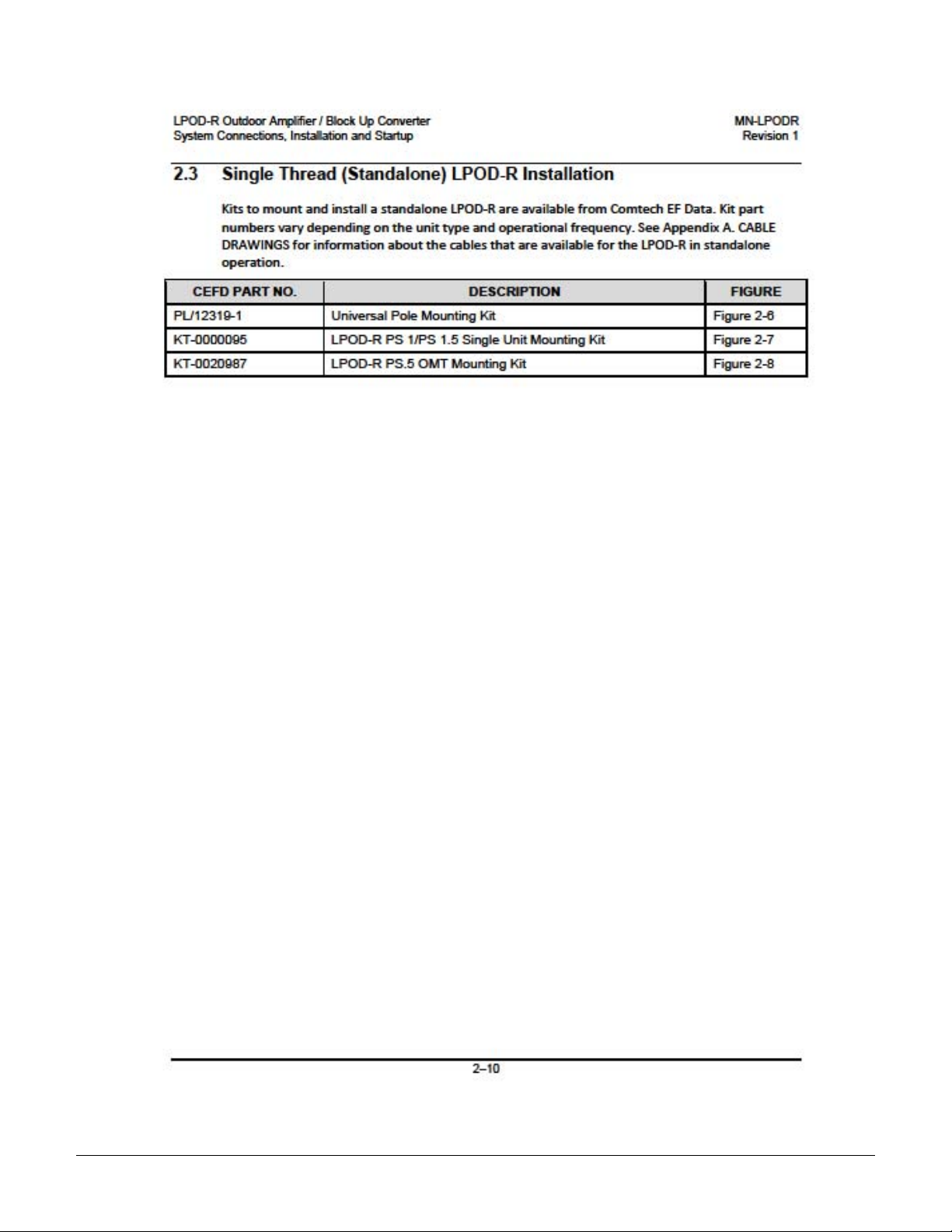
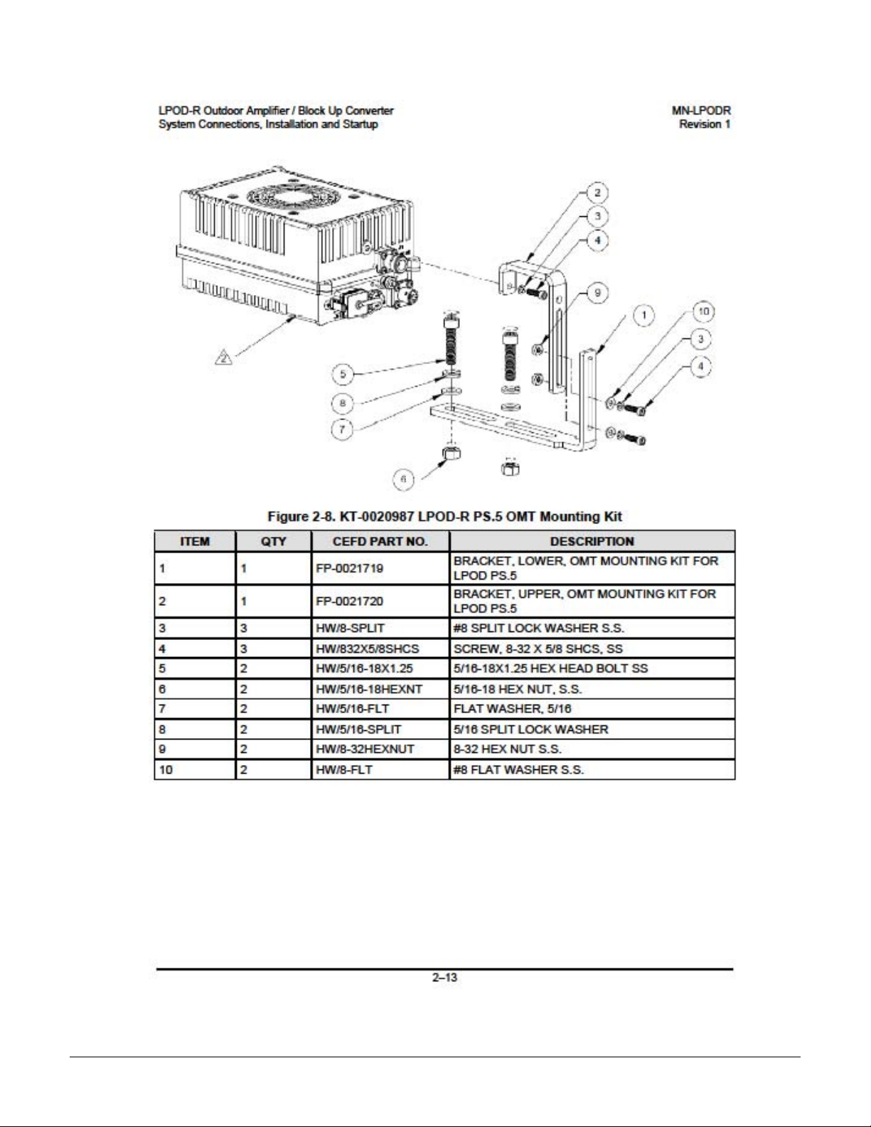
Update Section 2.3, added KT-0020987, LPOD-R PS.5 OMT Mounting Kit
Errata Part Number:
PLM CO Number:
Comments:
ER-LPODR-EA1 (Errata documents are not revised)
C-0032769
See attached page(s). The new information will be included in the next released revision
of the manual.
ER-LPODR-EA1 Rev - PLM C-0032769
Page 6
ER-LPODR-EA1 Rev - PLM C-0032769
Page 7
ER-LPODR-EA1 Rev - PLM C-0032769
Page 8
ER-LPODR-EA1 Rev - PLM C-0032769
Page 9
ER-LPODR-EA1 Rev - PLM C-0032769
Page 10
ER-LPODR-EA1 Rev - PLM C-0032769
Page 11
Errata B for MN-LPOD-R Rev 1
Comtech EF Data Documentation Update
Subject:
Add Appendix C. OPTIONAL SERIAL-BASED REMOTE PRODUCT MANAGEMENT, Customer Commands, all but PS.5
packages
Errata Part Number:
PLM CO Number:
Comments:
ER-LPODR-EB1 Rev - Page 1 of 28 PLM C-0033316
ER-LPODR-EB1 (Errata documents are not revised)
C-0033316
See attached page(s). The new information will be included in the next released revision of the manual.
Page 12
ER-LPODR-EB1 Rev - Page 2 of 28 PLM C-0033316
Page 13
ER-LPODR-EB1 Rev - Page 3 of 28 PLM C-0033316
Page 14
ER-LPODR-EB1 Rev - Page 4 of 28 PLM C-0033316
Page 15

ER-LPODR-EB1 Rev - Page 5 of 28 PLM C-0033316
Page 16

ER-LPODR-EB1 Rev - Page 6 of 28 PLM C-0033316
Page 17

ER-LPODR-EB1 Rev - Page 7 of 28 PLM C-0033316
Page 18

ER-LPODR-EB1 Rev - Page 8 of 28 PLM C-0033316
Page 19

ER-LPODR-EB1 Rev - Page 9 of 28 PLM C-0033316
Page 20

ER-LPODR-EB1 Rev - Page 10 of 28 PLM C-0033316
Page 21

ER-LPODR-EB1 Rev - Page 11 of 28 PLM C-0033316
Page 22

ER-LPODR-EB1 Rev - Page 12 of 28 PLM C-0033316
Page 23

ER-LPODR-EB1 Rev - Page 13 of 28 PLM C-0033316
Page 24

ER-LPODR-EB1 Rev - Page 14 of 28 PLM C-0033316
Page 25

ER-LPODR-EB1 Rev - Page 15 of 28 PLM C-0033316
Page 26

ER-LPODR-EB1 Rev - Page 16 of 28 PLM C-0033316
Page 27

ER-LPODR-EB1 Rev - Page 17 of 28 PLM C-0033316
Page 28
ER-LPODR-EB1 Rev - Page 18 of 28 PLM C-0033316
Page 29

ER-LPODR-EB1 Rev - Page 19 of 28 PLM C-0033316
Page 30

ER-LPODR-EB1 Rev - Page 20 of 28 PLM C-0033316
Page 31

ER-LPODR-EB1 Rev - Page 21 of 28 PLM C-0033316
Page 32

ER-LPODR-EB1 Rev - Page 22 of 28 PLM C-0033316
Page 33

ER-LPODR-EB1 Rev - Page 23 of 28 PLM C-0033316
Page 34

ER-LPODR-EB1 Rev - Page 24 of 28 PLM C-0033316
Page 35

ER-LPODR-EB1 Rev - Page 25 of 28 PLM C-0033316
Page 36

ER-LPODR-EB1 Rev - Page 26 of 28 PLM C-0033316
Page 37

ER-LPODR-EB1 Rev - Page 27 of 28 PLM C-0033316
Page 38

ER-LPODR-EB1 Rev - Page 28 of 28 PLM C-0033316
Page 39

TABLE OF CONTENTS
About this Manual .............................................................................................................................. ix
Related Documents .................................................................................................................................. ix
Disclaimer ................................................................................................................................................. ix
Conventions and References ................................................................................................................ x
Patents and Trademarks ........................................................................................................................... x
Warnings, Cautions, and Notes ................................................................................................................. x
Examples of Multi-Hazard Notices ............................................................................................................ x
Recommended Standard Designations ..................................................................................................... x
Electrical Safety Notice ....................................................................................................................... xi
Installation Guidelines Regarding Power Line Quality ......................................................................... xi
Product Support ................................................................................................................................. xii
Comtech EF Data Headquarters.......................................................................................................... xii
Warranty Policy ................................................................................................................................. xiii
Limitations of Warranty ..........................................................................................................................xiii
13B13BExclusive Remedies .................................................................................................................................xiii
CHAPTER 1. INTRODUCTION ............................................................................................. 1–1
1.1 Overview .............................................................................................................................. 1–1
1.2 Functional Description .......................................................................................................... 1–1
1.3 Features ............................................................................................................................... 1–2
1.3.1 The Solid-State Advantage ........................................................................................................ 1–2
1.3.2 “Smart BUC” Functionality ....................................................................................................... 1–2
1.3.3 Enhanced Standard Features .................................................................................................... 1–2
1.3.3.1 Advanced FSK .................................................................................................................... 1–2
1.3.3.2 Data Logging Capability ..................................................................................................... 1–2
1.3.3.3 Hand-Held Controller Devices ........................................................................................... 1–2
1.4 Theory of Operation ............................................................................................................. 1–3
1.4.1 SSPA Block Diagrams ................................................................................................................ 1–3
1.4.2 SSPA Module ............................................................................................................................. 1–3
1.4.3 Cooling System ......................................................................................................................... 1–4
1.4.4 Monitor and Control (M&C) ..................................................................................................... 1–4
1.4.5 Power Supply ............................................................................................................................ 1–4
1.4.6 Block Up Converter (BUC) Input ............................................................................................... 1–5
iii
Page 40

LPOD-R Outdoor Amplifier / Block Up Converter (BUC) MN-LPODR
Table of Contents Revision 1
1.5 Summary of Specifications .................................................................................................... 1–6
1.5.1 Characteristics .......................................................................................................................... 1–6
1.5.2 Environmental .......................................................................................................................... 1–8
1.5.3 Physical ..................................................................................................................................... 1–8
1.6 Dimensional Envelopes ......................................................................................................... 1–8
1.6.1 LPOD-R PS .5 Dimensional Envelopes ....................................................................................... 1–9
1.6.2 LPOD-R PS 1 Dimensional Envelopes ...................................................................................... 1–10
1.6.3 LPOD-R PS 1.5 Dimensional Envelopes ................................................................................... 1–12
CHAPTER 2. SYSTEM CONNECTIONS, INSTALLATION AND STARTUP ....................... 2–1
2.1 Overview .............................................................................................................................. 2–1
2.2 Interface Connectors ............................................................................................................ 2–3
2.2.1 Connector J1 | LBAND IN .......................................................................................................... 2–3
2.2.2 Connector J2 | RF OUT ............................................................................................................. 2–3
2.2.3 Connector J3 | POWER IN AC Power Mains ............................................................................. 2–3
2.2.3.1 LPOD-R PS 1, PS 1.5 J3 | POWER IN AC Power Main ........................................................ 2–4
2.2.4 Connector J3 | POWER IN Optional DC Power Mains .............................................................. 2–4
2.2.4.1 LPOD-R PS .5 J3 | POWER IN DC Power Main Option ....................................................... 2–4
2.2.4.2 LPOD-R PS 1 J3 | POWER IN DC Power Main Option ........................................................ 2–5
2.2.4.3 LPOD-R PS 1.5 J3 | POWER IN DC Power Main Option ..................................................... 2–5
2.2.5 Connector J6 | COM1 (Remote Communications and Discrete Control Port – PS 1, PS 1.5 ONLY)
2–6
2.2.6 Connector J6 | COM1 (Ethernet Communications Port – PS .5 ONLY).................................... 2–7
2.2.6.1 Fabricating a Weatherproof Ethernet Cable ..................................................................... 2–7
2.2.7 Ground Connector .................................................................................................................... 2–9
2.3 Single Thread (Standalone) LPOD-R Installation .................................................................. 2–10
2.4 Set the LPOD-R Power On ................................................................................................... 2–12
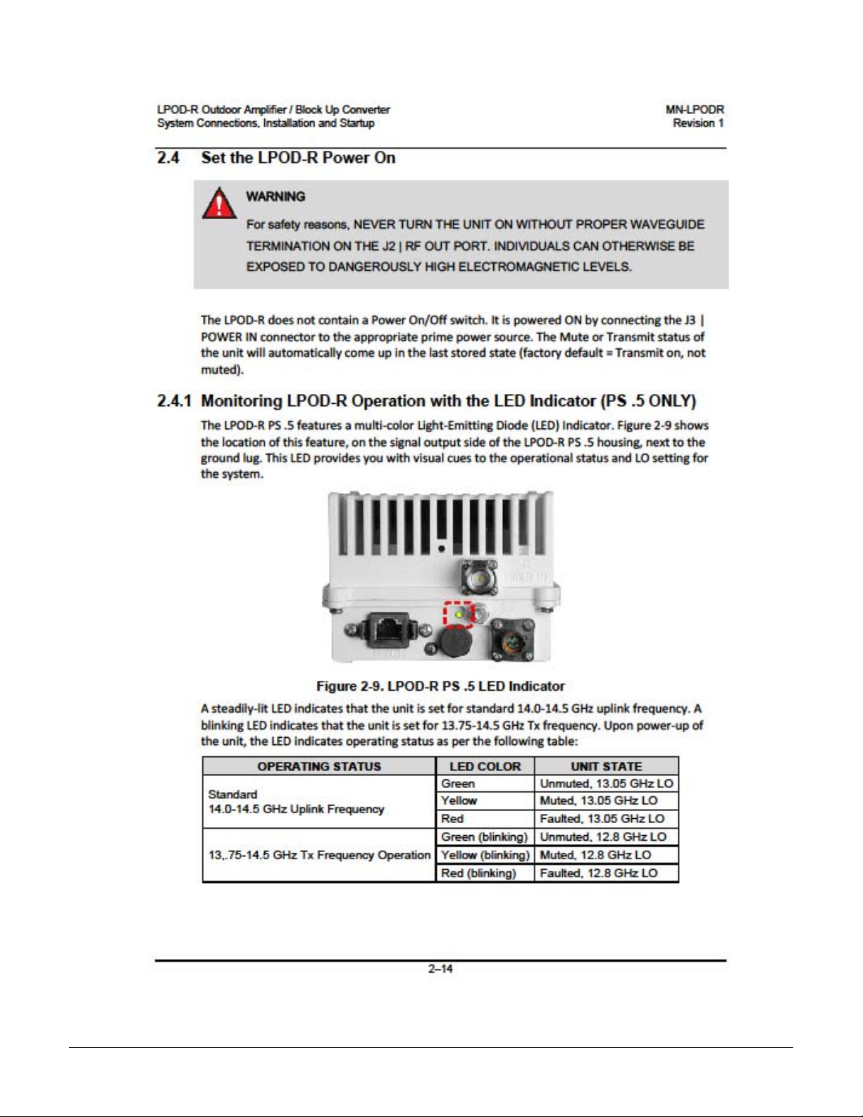
2.4.1 Monitoring LPOD-R Operation with the LED Indicator (PS .5 ONLY) ...................................... 2–12
CHAPTER 3. UPDATING FIRMWARE ................................................................................. 3–1
3.1 Introduction ......................................................................................................................... 3–1
3.1.1 LPOD-R Firmware Update Process Summary ........................................................................... 3–1
3.2 Prepare for the Firmware Download ..................................................................................... 3–1
3.2.1 Required User-supplied Items
.................................................................................................. 3–1
3.2.1.1 LPOD-R PS .5 connections ................................................................................................ 3–2
3.2.1.2 LPOD-R PS 1 or PS 1.5 connections ................................................................................... 3–2
3.2.2 Configure the Terminal Emulator Program, if necessary ......................................................... 3–3
3.2.3 Find the LPOD-R firmware and version numbers ..................................................................... 3–3
3.2.3.1 Use the Web Server Interface to find the firmware version ............................................ 3–3
3.2.3.2 Use the optional serial remote control to find the firmware version .............................. 3–4
iv
Page 41

LPOD-R Outdoor Amplifier / Block Up Converter (BUC) MN-LPODR
Table of Contents Revision 1
3.2.4 Make a temporary folder (subdirectory) on the User PC ......................................................... 3–4
3.2.5 Use the Windows Desktop to make a temporary folder .......................................................... 3–5
3.2.6 Use Windows Explorer to make a temporary folder ................................................................ 3–5
3.2.7 Use the Run and Browse windows to make a temporary folder.............................................. 3–5
3.2.8 Use Windows Command line to make a temporary folder ...................................................... 3–6
3.3 Download and Extract the Firmware Update Files ................................................................. 3–7
3.3.1 About Firmware Numbers, File Versions, and Formats ............................................................ 3–7
3.3.2 Steps to Download and Extract the Firmware Update Files ..................................................... 3–7
3.3.2.1 Use the Windows Desktop to see the folder contents ..................................................... 3–8
3.3.2.2 Use the Windows Command line to see the folder contents ........................................... 3–9
3.4 FTP Upload the Firmware Files and Update the LPOD-R Unit ................................................ 3–9
3.4.1 Important Considerations ......................................................................................................... 3–9
3.4.2 Steps to FTP Upload the Firmware Files ................................................................................... 3–9
3.4.3 Steps to Update the LPOD-R Unit ........................................................................................... 3–10
3.5 Recover the User Interface Access ....................................................................................... 3–11
3.5.1 Recovery Steps Using a Windows PC. ..................................................................................... 3–11
CHAPTER 4. ETHERNET-BASED REMOTE PRODUCT MANAGEMENT ......................... 4–1
4.1 Introduction ......................................................................................................................... 4–1
4.1.1 Prerequisites ............................................................................................................................. 4–1
4.2 SNMP Interface .................................................................................................................... 4–2
4.2.1 Management Information Base (MIB) Files .............................................................................. 4–2
4.2.1.1 ComtechEFData Root MIB file ........................................................................................... 4–2
4.2.1.2 LPOD-R MIB file ................................................................................................................. 4–3
4.2.1.3 LPOD-R Traps MIB file ...................................................................................................... 4–3
4.2.2 SNMP Community Strings ......................................................................................................... 4–3
4.3 Telnet Interface .................................................................................................................... 4–4
4.3.1 Using the Telnet Interface for Remote Control Operation ....................................................... 4–4
4.3.2 Using HyperTerminal for Telnet Remote Control Operation ................................................... 4–4
4.4 Web Server (HTTP) Interface ................................................................................................. 4–7
4.4.1 Enable the Web Server Interface .............................................................................................. 4–7
4.4.2 User Login ................................................................................................................................. 4–8
4.4.3 Web Server Interface Operation .............................................................................................. 4–9
4.4.3.1 Menu Tree ......................................................................................................................... 4–9
4.4.3.2 Page Navigation ................................................................................................................ 4–9
4.4.3.3 Page Sections .................................................................................................................... 4–9
4.4.3.4 Action Buttons .................................................................................................................. 4–9
4.4.3.5 Drop-down Lists .............................................................................................................. 4–10
4.4.3.6 Text or Data Entry ........................................................................................................... 4–10
4.4.4 Home Pages ............................................................................................................................ 4–10
v
Page 42

LPOD-R Outdoor Amplifier / Block Up Converter (BUC) MN-LPODR
Table of Contents Revision 1
4.4.4.1 Home | Home ................................................................................................................. 4–10
4.4.4.2 Home | Contact / Home | Support pages ....................................................................... 4–10
4.4.5 Admin Pages ........................................................................................................................... 4–11
4.4.5.1 Admin | Access................................................................................................................ 4–11
4.4.5.2 Admin | SNMP ................................................................................................................ 4–13
4.4.6 Config Pages............................................................................................................................ 4–14
4.4.6.1 Config | Amplifier ............................................................................................................ 4–14
4.4.6.2 Config | Utility ................................................................................................................. 4–15
4.4.7 Status Pages ............................................................................................................................ 4–17
4.4.7.1 Status | Summary ........................................................................................................... 4–17
4.4.7.2 Status | Status ................................................................................................................. 4–18
4.4.7.3 Status | MOP ................................................................................................................... 4–19
4.4.7.4 Status | Events ................................................................................................................ 4–20
4.4.7.5 Status | Statistics ............................................................................................................ 4–21
4.4.7.6 Status | Trending Graphs ................................................................................................ 4–22
CHAPTER 5. OPTIONAL SERIAL-BASED REMOTE PRODUCT MANAGEMENT ............ 5–1
5.1 Overview .............................................................................................................................. 5–1
5.2 Key Operational Parameters / Common Commands and Queries) ........................................ 5–1
5.2.1 End-of-Life Commands ............................................................................................................. 5–3
5.3 Remote Control Protocol and Structure ................................................................................ 5–3
5.3.1 EIA-485 ...................................................................................................................................... 5–3
5.3.2 EIA-232 ...................................................................................................................................... 5–4
5.3.3 Basic Protocol ........................................................................................................................... 5–4
5.3.4 Packet Structure ....................................................................................................................... 5–5
5.3.4.1 Start of Packet ................................................................................................................... 5–5
5.3.4.2 Target Address .................................................................................................................. 5–6
5.3.4.3 Address Delimiter .............................................................................................................. 5–6
5.3.4.4 Instruction Code ................................................................................................................ 5–6
5.3.4.5 Instruction Code Qualifier ................................................................................................. 5–6
5.3.4.6 Optional Message Arguments ........................................................................................... 5–7
5.3.4.7 End of Packet ................................................................
.................................................... 5–7
5.4 Remote Commands and Queries ........................................................................................... 5–8
APPENDIX A. CABLE DRAWINGS ...................................................................................... A-1
A.1 Overview ............................................................................................................................... A-1
A.2 Control and Data Cables ........................................................................................................ A-1
A.2.1 Serial Interface Cable ................................................................................................................ A-2
A.2.2 Ethernet Interface Cable ........................................................................................................... A-3
A.2.3 Ethernet Data Cable (CAT5 RJ-45) ............................................................................................ A-4
vi
Page 43

LPOD-R Outdoor Amplifier / Block Up Converter (BUC) MN-LPODR
Table of Contents Revision 1
A.3 RF Cables ............................................................................................................................... A-5
A.3.1 RF Cable (Type N) ...................................................................................................................... A-6
APPENDIX B. MAINTENANCE ............................................................................................ B–1
B.1 Introduction ......................................................................................................................... B–1
B.2 Cleaning the LPOD-R PS .5 Heat Sinks ................................................................................... B–2
B.3 Cleaning the LPOD-R PS 1 Heat Sinks (FUTURE) ..................................................................... B–6
B.4 Cleaning the LPOD-R PS 1.5 Heat Sinks (FUTURE) .................................................................. B–9
TABLES
Table 2-1. J2 | RF OUT Interface Type ..................................................................................................... 2–3
Table 2-2. LPOD-R PS 1/PS 1.5 J3 | POWER IN Pin Assignments ......................................................... 2–4
Table 2-3. LPOD-R PS 1 J3 | POWER IN Pin Assignments .................................................................... 2–5
Table 2-4. LPOD-R PS 1 J3 | POWER IN Pin Assignments .................................................................... 2–5
Table 2-5. LPOD-R PS 1.5 J3 | POWER IN Pin Assignments ................................................................. 2–5
Table 2-6. LPOD-R J6 | COM1 Pin Assignment s ..................................................................................... 2–6
FIGURES
Figure 1-1. Comtech EF Data LPOD-R Outdoor Amplif iers / BUCs ......................................................... 1–1
Figure 1-2. LPOD-R Typical Block Diagram ............................................................................................. 1–3
Figure 1-3. LPOD-R PS .5 LED Indicator ................................................................................................. 1–4
Figure 1-4. LPOD-R PS .5 Ku-Band Unit – DC Power, Waveguide Output ............................................. 1–9
Figure 1-5. LPOD-R PS 1 C-Band Unit – AC Power, Coaxial Output (FUTURE) .................................. 1–10
Figure 1-6. LPOD-R PS 1 C-Band Unit – AC Power, Waveguide Output (FUTU RE) ............................ 1–11
Figure 1-7. LPOD-R PS 1.5 Ku-Band Unit – AC or DC Power, Waveguide Output (FUTURE ) ............. 1–12
Figure 2-1. LPOD-R PS .5 Connectors ..................................................................................................... 2–2
Figure 2-2. LPOD-R PS 1 Connectors ...................................................................................................... 2–2
Figure 2-3. LPOD-R PS 1.5 Connectors ................................................................................................... 2–2
Figure 2-4. LPOD-R Ethernet Connector Field Terminati on Kit Assembly ............................................... 2–8
Figure 2-5. LPOD-R Ground Connector Locations ................................................................................... 2–9
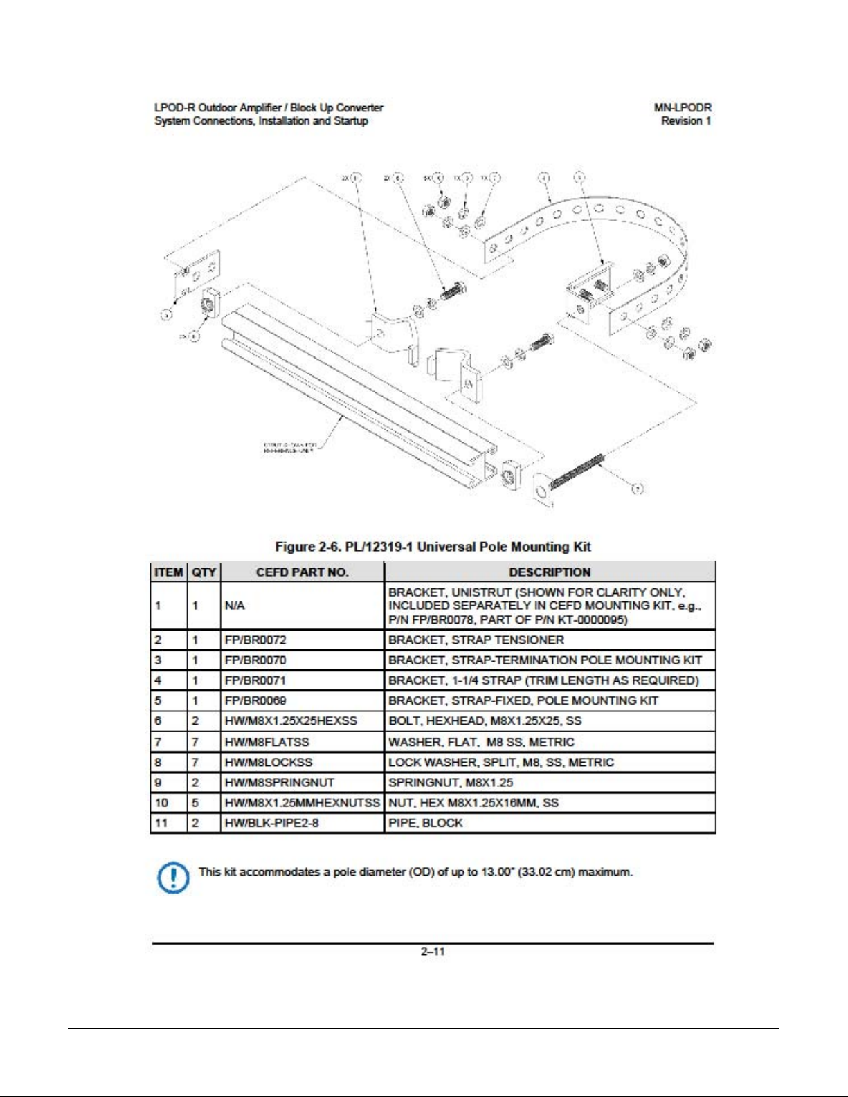
Figure 2-6. PL/12319-1 Universal Pole Mounting Ki t .............................................................................. 2–10
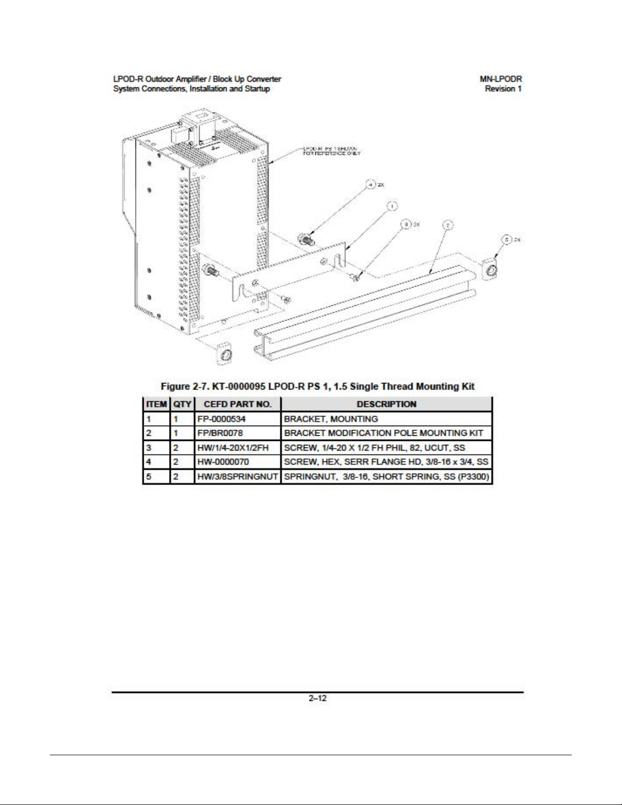
Figure 2-7. KT-0000095 LPOD-R PS 1, 1.5 Single Thread Mounting Kit ............................................... 2–11
Figure 2-8. LPOD-R PS .5 LED Indicator ............................................................................................... 2–12
Figure 3-1. Monitor and Control Utilities Avai l abl e from Comtech EF Data .............................................. 3–2
Figure 4-1. LPOD-R .5 Unit Home Page ................................................................................................. 4–10
Figure 4-2. Admin | Access Page ............................................................................................................ 4–11
Figure 4-3. Admin | SNMP Page ............................................................................................................. 4–13
Figure 4-4. Config | Amplifier Page ......................................................................................................... 4–14
Figure 4-5. Config | Utility Page ........................................................................................................... 4–15
Figure 4-6. Status | Summary Page ........................................................................................................ 4–17
Figure 4-7. Status | Status Page ............................................................................................................. 4–18
vii
Page 44

LPOD-R Outdoor Amplifier / Block Up Converter (BUC) MN-LPODR
Table of Contents Revision 1
Figure 4-8. Status | MOP Page ............................................................................................................... 4–19
Figure 4-9. Status | Events Page ............................................................................................................ 4–20
Figure 4-9. Status | Statistics Page ......................................................................................................... 4–21
Figure 4-11. Status | Trending Graphs Exam ple .................................................................................... 4–22
Figure 4-12. Status | Trending Graphs Exam ple, continued ................................................................... 4–23
Figure A-1. Serial Interface Cable (CEFD P/N CA-0020526, part of KT-0020518) .................................. A-2
Figure A-2. Ethernet Interface Cable (CEFD P/ N CA-0000352, part of KT-0000203) ............................. A-3
Figure A-3. Ethernet Data Cable (CEFD P/N PP/CAT5FF7FTGY) .......................................................... A-4
Figure A-4. 1/4" Heliax Coaxial Cable (CA/ 3722-X) ................................................................................. A-6
Figure B-1. Comtech EF Data LPOD-R Outdoor Amplifiers / BUCs ......................................................... B–1
Figure B-2. LPOD-R PS .5 Cover Plate Screw Locations ........................................................................ B–3
Figure B-3. Remove the Cover Plate ........................................................................................................ B–3
Figure B-4. Set Aside the Fan Assembly .................................................................................................. B–4
Figure B-5. LPOD-R PS .5 Heat Sink Locations (Fan Not Shown for Clarity) .......................................... B–4
Figure B-6. Reseat the Fan Assembly ...................................................................................................... B–5
Figure B-7. Replace the Cover Plate ........................................................................................................ B–5
Figure B-8. LPOD-R PS 1 Shroud Screw Locations ................................................................................. B–7
Figure B-9. Remove the Fan Shroud ........................................................................................................ B–7
Figure B-10. Disconnect the Fan Power Supply ....................................................................................... B–8
Figure B-11. LPOD-R PS 1 Heat Sink Locations ...................................................................................... B–8
Figure B-12. Reconnect the Fan Power Supply........................................................................................ B–8
Figure B-13. LPOD-R PS 1.5 Shroud Screw Locations .......................................................................... B–10
Figure B-14. Remove the Fan Shroud .................................................................................................... B–11
Figure B-15. Disconnect the Fan 1 / Fan 2 Power Supplies ................................................................... B–11
Figure B-16. LPOD-R PS 1.5 Heat Sink Location .................................................................................. B–12
Figure B-17. Reconnect the Fan 1 / Fan 2 Power Supplies ................................................................... B–12
viii
Page 45

About this Manual
This manual is applicable to LPOD-R units as listed:
• LPOD-R PS 1 and 1.5 units, all firmware versions.
• LPOD-R PS.5 units, firmware FW-0020841 and later.
Earlier LPOD-R PS 0.5 units with FW-0020765 are documented in the LPOD-R manual,
revision 0.
PREFACE
This manual gives installation and operation information for the Comtech EF Data LPOD-R family
of Outdoor Amplifiers / Block Up Converter (BUCs). This document is meant for anyone who
installs or operates the LPOD-R.
Related Documents
• Comtech EF Data CLC-10 Handheld Terminal M&C Accessory for LPOD or SPOD PS 1, PS 1.5, PS 2
User’s Guide (CEFD P/N MN-CLC10)
• Comtech EF Data LPODnet M&C Netbook Accessory for LPOD or SPOD PS 1, PS 1.5, PS 2
Operation Manual (CEFD P/N MN-LPODNET)
Disclaimer
Comtech EF Data has reviewed this manual thoroughly in order to provide an easy-to-use guide to
this equipment. All statements, technical information, and recommendations in this manual and in
any guides or related documents are believed reliable, but the accuracy and completeness thereof
are not guaranteed or warranted, and they are not intended to be, nor should they be understood
to be, representations or warranties concerning the products described. Further, Comtech EF Data
reserves the right to make changes in the specifications of the products described in this manual at
any time without notice and without obligation to notify any person of such changes.
Contact Comtech EF Data Product Support if you have any questions regarding this
equipment or the information in this manual.
ix
Page 46

LPOD-R Outdoor Amplifier / Block Up Converter (BUC) MN-LPODR
WARNING
CAUTION
Preface Revision 1
Conventions and References
Patents and Trademarks
See all of Comtech EF Data's Patents and Patents Pending at http://patents.comtechefdata.com.
Comtech EF Data acknowledges that all trademarks are the property of the trademark owners.
Warnings, Cautions, and Notes
A
SERIOUS INJURY.
A
PROPERTY DAMAGE.
A NOTE gives you important information about a task or the equipment.
A REFERENCE directs you to additional information about a task or the equipment.
informs you about a possible hazard that MAY CAUSE DEATH or
informs you about a possible hazard that MAY CAUSE INJURY or
Examples of Multi-Hazard Notices
Recommended Standard Designations
The new designation of the Electronic Industries Association (EIA) supersedes the Recommended
Standard (RS) designations. References to the old designations may be shown when depicting
actual text (e.g., RS-232) displayed on the physical product, LPOD-R Web Server pages or optional
serial remote interface. All other references in the manual refer to EIA designations.
x
 Loading...