

Page 1

C-/Ku-Band Outdoor Amplifier/Block Up Converter (BUC)
Installation and Operation Manual
LPOD
Part Number MN-LPOD
Revision 0
IMPORTANT NOTE: The information contained in this document supersedes all previously published
information regarding this product. Product specifications are subject to change without prior notice.
Page 2

Page 3

LPOD
C-/Ku-Band Outdoor Amplifier/Block Up Converter (BUC)
Installation and Operation Manual
Part Number MN-LPOD
Revision 0
October 17, 2008
Copyright © 2008 Comtech EF Data. All rights reserved. Printed in the USA.
Comtech EF Data, 2114 West 7th Street, Tempe, Arizona 85281 USA, 480.333.2200, FAX: 480.333.2161
Page 4

This page is intentionally blank.
ii
Page 5

Table of Contents
TABLE OF CONTENTS .............................................................................................................. III
TABLES ....................................................................................................................................... V
FIGURES ..................................................................................................................................... V
PREFACE .................................................................................................................................. VII
Customer Support ..................................................................................................................................... vii
About this Manual ................................................................................................................................... viii
Reporting Comments or Suggestions Concerning this Manual ............................................................. viii
Conventions and References ................................................................................................................... viii
Cautions and Warnings .......................................................................................................................... viii
Recommended Standard Designations ................................................................................................... viii
Trademarks .............................................................................................................................................. ix
Metric Conversion ................................................................................................................................... ix
Electrical Safety Notice .............................................................................................................................. ix
Installation Guidelines Regarding Power Line Quality ......................................................................... ix
Warranty Policy .......................................................................................................................................... x
Limitations of Warranty ............................................................................................................................ x
Exclusive Remedies ................................................................................................................................. xi
CHAPTER 1. INTRODUCTION ............................................................................................. 1–1
1.1 Overview ...................................................................................................................................... 1–1
1.2 Functional Description ............................................................................................................... 1–2
1.3 Features ........................................................................................................................................ 1–2
1.3.1 The Solid-State Advantage ................................................................................................... 1–2
1.3.2 Enhanced Standard Features ................................................................................................. 1–2
1.3.3 Built-In Redundancy Controller ............................................................................................ 1–2
1.3.4 “Smart BUC” Functionality .................................................................................................. 1–3
1.3.5 Data Logging Capability ....................................................................................................... 1–3
1.3.6 Optional Internal 10 MHz Reference .................................................................................... 1–3
1.3.7 Optional LNB Support .......................................................................................................... 1–3
1.4 Theory of Operation ................................................................................................................... 1–4
1.4.1 SSPA Block Diagrams .......................................................................................................... 1–4
iii
Page 6

LPOD C-/Ku-Band Outdoor Amplifier/Block Up Converter (BUC) Revision 0
Table of Contents MN-LPOD
1.4.2 SSPA Module ........................................................................................................................ 1–5
1.4.3 Cooling System ..................................................................................................................... 1–6
1.4.4 Monitor and Control (M&C) ................................................................................................. 1–6
1.4.5 LNB Operation ...................................................................................................................... 1–6
1.4.6 Power Supply ........................................................................................................................ 1–6
1.4.7 Block Up Converter (BUC) Input ......................................................................................... 1–7
1.5 Summary of Specifications ......................................................................................................... 1–8
1.5.1 Characteristics ....................................................................................................................... 1–8
1.5.2 Optional Internal Reference .................................................................................................. 1–9
1.5.3 Optional LNB Bias / Reference ............................................................................................ 1–9
1.5.4 Environmental ..................................................................................................................... 1–10
1.5.5 Physical ............................................................................................................................... 1–10
1.6 Dimensional Envelopes ............................................................................................................. 1–11
CHAPTER 2. SYSTEM CONNECTIONS AND OPERATION ............................................... 2–1
2.1 Overview ...................................................................................................................................... 2–1
2.2 Interface Connectors................................................................................................................... 2–2
2.2.1 Connector J1 – RF IN ........................................................................................................... 2–2
2.2.2 Connector J2 – RF OUT ....................................................................................................... 2–2
2.2.3 Connector J3 – AC Power Mains .......................................................................................... 2–2
2.2.3.1 LPOD PS-1 J3 AC Power Main ........................................................................................ 2–3
2.2.3.2 LPOD PS-2 J3 AC Power Main ........................................................................................ 2–3
2.2.4 C o n n e c t o r J6 – C O M 1 ( R e mot e C o m mun i c a t i o n s a nd D i s c r e t e Co n t r o l Por t ) ..................................... 2–4
2.2.5 Connector J9 – Output Sample (PS-2 Only) ......................................................................... 2–5
2.2.6 Connectors J10 and J11 – Optional Modem Rx and LNB Interfaces ................................... 2–5
2.2.7 Ground Connector ................................................................................................................. 2–5
2.3 Installation of the LPOD ............................................................................................................ 2–6
2.3.1 Universal Pole Mounting Kit PL/12319-1 ............................................................................ 2–6
2.4 Turning on the LPOD ................................................................................................................. 2–7
CHAPTER 3. REMOTE COMMANDS ................................................................................... 3–1
3.1 Introduction ................................................................................................................................. 3–1
3.1.1 RF Input Level ...................................................................................................................... 3–1
3.1.2 Attenuator Control ............................................................................................................ .... 3–1
3.1.3 Mute Control ............................................................................................................................. 3–1
3.1.4 Faults ..................................................................................................................................... 3–2
3.1.5 Power Detector ...................................................................................................................... 3–2
3.1.6 Some Common Commands .................................................................................................. 3–2
3.2 Remote Control Protocol and Structure ................................................................................... 3–2
3.2.1 RS-485 .................................................................................................................................. 3–3
3.2.2 RS-232 .................................................................................................................................. 3–3
iv
Page 7

LPOD C-/Ku-Band Outdoor Amplifier/Block Up Converter (BUC) Revision 0
Table of Contents MN-LPOD
3.2.3 Basic Protocol ....................................................................................................................... 3–3
3.2.4 Packet Structure .................................................................................................................... 3–4
3.2.4.1 Start of Packet ................................................................................................................... 3–4
3.2.4.2 Address ............................................................................................................................. 3–4
3.2.4.3 Instruction Code ................................................................................................................ 3–5
3.2.4.4 Instruction Code Qualifier ................................................................................................ 3–5
3.2.4.5 Message Arguments .......................................................................................................... 3–6
3.2.4.6 End of Packet .................................................................................................................... 3–6
3.2.4.7 End-of-Life Commands .................................................................................................... 3–6
3.3 Remote Commands and Queries ............................................................................................... 3–7
APPENDIX A. REDUNDANCY (PHASE 2 RELEASE) ........................................................ A–1
A.1 Introduction to Redundancy Operation .................................................................................. A–1
A.2 1:1 Redundancy Mode ............................................................................................................... A–1
A.3 1:2 Redundancy Mode ............................................................................................................... A–1
A.4 Applicable Redundancy Commands ........................................................................................ A–2
A.5 Redundancy System Assembly Kits ......................................................................................... A–2
Tables
Table 2-1. Waveguide Output Flange ......................................................................................... 2–2
Table 2-2. LPOD PS-1 ‘J3 PWR IN’ Pin Assignments .............................................................. 2–3
Table 2-3. LPOD PS-2 ‘J3 PWR IN’ Pin Assignments .............................................................. 2–3
Table 2-4. Connector J6 Pinout .................................................................................................. 2–4
Figures
Figure 1-1. Comtech EF Data LPOD C-/Ku-Band Outdoor Amplifier / BUC .......................... 1–1
Figure 1-2. LPOD PS-1 Block Diagram ..................................................................................... 1–4
Figure 1-3. LPOD PS-2 Block Diagram ..................................................................................... 1–5
Figure 1-4. LPOD PS-1 Dimensional Envelope ....................................................................... 1–11
Figure 1-5. LPOD PS-2 Dimensional Envelope ....................................................................... 1–12
Figure 2-1. LPOD Connectors .................................................................................................... 2–1
Figure 2-2. LPOD Ground Connectors ....................................................................................... 2–5
Figure 2-3. Universal Pole Mounting Kit, PL/12319-1 .............................................................. 2–6
v
Page 8

LPOD C-/Ku-Band Outdoor Amplifier/Block Up Converter (BUC) Revision 0
Table of Contents MN-LPOD
This page is intentionally blank.
vi
Page 9

Customer Support
Contact the Comtech EF Data Customer Support Department for:
• Product support or training
• Reporting comments or suggestions concerning manuals
• Information on upgrading or returning a product
A Customer Support representative may be reached at:
Comtech EF Data
Attention: Customer Support Department
2114 West 7th Street
Tempe, Arizona 85281 USA
480.333.2200 (Main Comtech EF Data number)
480.333.4357 (Customer Support Desk)
480.333.2161 FAX
To return a Comtech EF Data product (in-warranty and out-of-warranty) for repair or
replacement:
PREFACE
• Contact the Comtech EF Data Customer Support Department. Be prepared to supply the
Customer Support representative with the model number, serial number, and a description
of the problem.
• Request a Return Material Authorization (RMA) number from the Comtech EF Data
Customer Support representative.
• Pack the product in its original shipping carton/packaging to ensure th at the product is not
damaged during shipping.
• Ship the product back to Comtech EF Data. (Shipping charges should be prepaid.)
For Online Customer Support:
An RMA number request can be requested electronically by contacting the Customer Support
Department through the online support page at
• Click on “Service” for detailed instructions on our return procedures.
• Click on the “RMA Request Form” hyperlink, then fill out the form completely before
sending.
• Send e-mail to the Customer Support Department at service@comtechefdata.com.
For information regarding this product’s warranty policy, refer to the
www.comtechefdata.com/support.asp:
Warranty Policy, p. x.
vii
Page 10

LPOD C-/Ku-Band Outdoor Amplifier/Block Up Converter (BUC) Revision 0
Preface MN-LPOD
About this Manual
This manual provides installation and operation information for the Comtech EF Data LPOD
C-/Ku-Band Outdoor Amplifier / Block Up Converter (BUC). This is a technical document
intended for earth station engineers, technicians, and operators responsible for the operation and
maintenance of the LPOD PS-1 or PS-2.
Comtech EF Data has reviewed this manual thoroughly in order to provide an easy-to-use guide
to your equipment. All statements, technical information, and recommendations in this manual
and in any guides or related documents are believed reliable, but the accuracy and completeness
thereof are not guaranteed or warranted, and they are not intended to be, nor should they be
understood to be, representations or warranties concerning the products described. Further,
Comtech EF Data reserves the right to make changes in the specifications of the products
described in this manual at any time without notice and without obligation to notify any person of
such changes.
If you have any questions regarding your equipment or the information in this manual, contact the
Comtech EF Data Customer Support Department.
Reporting Comments or Suggestions Concerning this Manual
Comments and suggestions regarding the content and design of this manual will be appreciated.
To submit comments, please contact the Comtech EF Data Technical Publications Department:
TechnicalPublications@comtechefdata.com
.
Conventions and References
Cautions and Warnings
CAUTION indicates a hazardous situation that, if not avoided, may result in
minor or moderate injury. CAUTION may also be used to indicate other unsafe
CAUTION
WARNING
IMPORTANT
practices or risks of property damage.
WARNING indicates a potentially hazardous situation that, if not avoided,
could result in death or serious injury.
Indicates information critical for proper equipment function.
Recommended Standard Designations
Recommended Standard (RS) Designations have been superseded by the new designation of the
Electronic Industries Association (EIA). References to the old designations are shown only when
viii
Page 11

LPOD C-/Ku-Band Outdoor Amplifier/Block Up Converter (BUC) Revision 0
p
Preface MN-LPOD
depicting actual text displayed on the screen of the unit (RS-232, RS-485, etc.). All other references
in the manual will be shown with the EIA designations.
Trademarks
Other product names mentioned in this manual may be trademarks or registered trademarks of
their respective companies and are hereby acknowledged.
Metric Conversion
Metric conversion information is located on the inside back cover of this manual. This information
is provided to assist the operator in cross-referencing non-metric to metric conversions.
Electrical Safety Notice
This equipment has been designed to minimize exposure of personnel to hazards. For further
information, contact Comtech EF Data, Customer Support Department. The operators and
technicians must:
• Know how to work around, with, and on high voltage equipment.
• Exercise every precaution to ensure personnel safety.
• Exercise extreme care when working near high voltages.
• Be familiar with the warnings presented in this manual.
A Neutral Fusing - Double pole/ neutral fusing used on the prime power
CAUTION
supply input.
Installation Guidelines Regarding Power Line Quality
Comtech EF Data has become familiar with the varying quality of the AC
ower grid around the world. The following offers some installation guidelines
IMPORTANT
• Surge suppression: High voltage surges can cause failure of the power supply. These surges
are typically caused by circuit switching on the main AC power grid, erratic generator
operation, and also by lightning strikes. While the LPOD does have built in surge
suppression, if the unit will be installed in a location with questionable power grid quality,
Comtech EF Data recommends installation of additional power conditioning/surge
suppression at the power junction box.
• Grounding: The LPOD provides a grounding terminal. This is provided to allow the user to
ground the LPOD to the antenna’s grounding network. All components installed at the
antenna should be grounded to a common grounding point at the antenna.
that should help ensure a reliable installation.
ix
Page 12

LPOD C-/Ku-Band Outdoor Amplifier/Block Up Converter (BUC) Revision 0
Preface MN-LPOD
• Electrical welding: If welding needs to take place at the antenna, disconnect all cables from
the LPOD except for the ground wire. Cap all RF connections with terminations. This will
prevent damage to the input/output circuitry of the LPOD.
• Lightning: Lightning strikes on or around the antenna will generate extremely high voltages
on all cables connected to the LPOD. Depending on the severity of the strike, the LPOD’s
internal surge protection combined with the recommended external suppression may protect
the LPOD’s power supply. However, if the installation will be in an area with a high
probability of lightning strikes, Comtech EF Data recommends the installation of surge
suppression on the RF and IF cables. One source of these suppressors is PolyPhaser
(www.polyphaser.com).
Warrant y Policy
Comtech EF Data products are warranted against defects in material and workmanship
for a period of two years from the date of shipment. During the warranty period, Comtech
EF Data will, at its option, repair or replace products that prove to be defective.
For equipment under warranty, the owner is responsible for freight to Comtech EF Data
and all related customs, taxes, tariffs, insurance, etc. Comtech EF Data is responsible for
the freight charges only for return of the equipment from the factory to the owner. Comtech
EF Data will return the equipment by the same method (i.e., Air, Express, Surface) as the
equipment was sent to Comtech EF Data.
All equipment returned for warranty repair must have a valid RMA number issued prior
to return and be marked clearly on the return packaging. Comtech EF Data strongly
recommends all equipment be returned in its original packaging.
Comtech EF Data Corporation’s obligations under this warranty are limited to repair or
replacement of failed parts, and the return shipment to the buyer of the repaired or
replaced parts.
Limitations of Warranty
The warranty does not apply to any part of a product that has been installed, altered,
repaired, or misused in any way that, in the opinion of Comtech EF Data Corporation,
would affect the reliability or detracts from the performance of any part of the product, or
is damaged as the result of use in a way or with equipment that had not been previously
approved by Comtech EF Data Corporation.
The warranty does not apply to any product or parts thereof where the serial number or the
serial number of any of its parts has been altered, defaced, or removed.
The warranty does not cover damage or loss incurred in transportation of the product.
x
Page 13

LPOD C-/Ku-Band Outdoor Amplifier/Block Up Converter (BUC) Revision 0
Preface MN-LPOD
The warranty does not cover replacement or repair necessitated by loss or damage from
any cause beyond the control of Comtech EF Data Corporation, such as lightning or other
natural and weather related events or wartime environments.
The warranty does not cover any labor involved in the removal and or reinstallation of
warranted equipment or parts on site, or any labor required to diagnose the necessity for
repair or replacement.
The warranty excludes any responsibility by Comtech EF Data Corporation for incidental or
consequential damages arising from the use of the equipment or products, or for any inability
to use them either separate from or in combination with any other equipment or products.
A fixed charge established for each product will be imposed for all equipment returned
for warranty repair where Comtech EF Data Corporation cannot identify the cause of the
reported failure.
Exclusive Remedies
Comtech EF Data Corporation’s warranty, as stated is in lieu of all other warranties,
expressed, implied, or statutory, including those of me rchantability and fitness for a particular
purpose. The buyer shall pass on to any purchaser, lessee, or other user of Comtech EF Data
Corporation’s products, the aforementioned warranty, and shall indemnify and hold harmless
Comtech EF Data Corporation from any claims or liability of such purchaser, lessee, or user
based upon allegations that the buyer, its agents, or employees have made additional
warranties or representations as to product preference or use.
The remedies provided herein are the buyer’s sole and exclusive remedies. Comtech EF
Data shall not be liable for any direct, indirect, special, incidental, or consequential
damages, whether based on contract, tort, or any other legal theory.
xi
Page 14

LPOD C-/Ku-Band Outdoor Amplifier/Block Up Converter (BUC) Revision 0
Preface MN-LPOD
Notes:
xii
Page 15
1.1 Overview
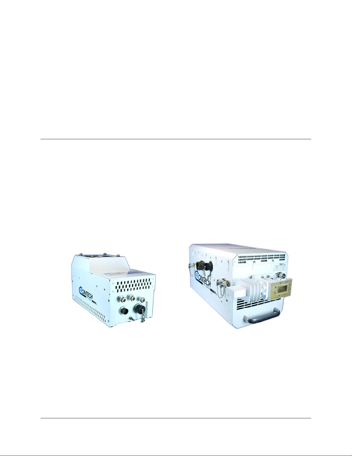
Comtech EF Data’s LPOD C-/Ku-Band Outdoor Amplifier/Block Up Converter (BUC) – referred
to throughout this manual as the LPOD – delivers its rated power, guaranteed, to the transmit
waveguide flange at the 1 dB compression point. It provides a cost effective, more reliable
replacement for Traveling Wave Tube (TWT) amplifiers in satellite communications.
Comtech EF Data’s extensive experience in the design of outdoor RF transceivers led to the
LPOD family’s efficient thermal and mechanical package. Recognizing the evolution of L-Band
IF systems, the LPOD is designed to eliminate the traditional requirement for the modem to
supply a DC power source and a 10 MHz reference to the BUCs and LNBs.
Chapter 1. INTRODUCTION
PS-1 Model PS-2 Model
Figure 1-1. Comtech EF Data LPOD C-/Ku-Band Outdoor Amplifier / BUC
1–1
Page 16

LPOD C-/Ku-Band Outdoor Amplifier / Block Up Converter (BUC) Revision 0
Introduction MN-LPOD
1.2 Functional Description
The compact size and weight of the LPOD lends itself to any installation with limited available
mounting space. These include ship-borne antenna systems, small “flyaway” systems, and
Satellite News Gathering (SNG) installations. The addition of the optional internal reference and
LNB bias T facilitates multi-carrier and redundant operations required of small-to medium-sized
hub installations.
As shown in Figure 1-1, Comtech EF Data’s LPOD is available in two package styles: the PS-1
model and the PS-2 model. Each LPOD consists of a CEFD SSPA module with the
Monitor/Control Processor (MCP), a power supply, and a fan assembly. The amplifier features a
Comtech EF Data low loss combining technique and MCP-based temperature-versus-gain
compensation.
The PS-1 model is always configured as a BUC/SSPA (L-Band in, RF out) with available power
levels to 50W; the PS-2 version can be configured as an integrated BUC/SSPA or solely as an
SSPA (RF in, RF out) at power levels to 250W.
1.3 Features
1.3.1 The Solid-State Advantage
The LPOD is constructed with highly reliable gallium arsenide field-effect transistors (GaAs
FETs). With third order intermodulation products that are 4 to 6 dB better than TWT ratings, the
CEFD unit replaces TWTs with saturated power levels of up to twice the LPOD’s rated output.
The LPODs also provide mean time between failures (MTBF) that is four to five times greater
than the typical TWT MTBF.
1.3.2 Enhanced Standard Features
The LPOD comes equipped with useful features that other manufacturers offer only as options.
Included in the base price are temperature compensation, sample ports (on the PS-2 only), power
monitor, power factor corrected supply, and full remote monitor and control (M&C) capabilities
(including Ethernet and serial).
1.3.3 Built-In Redundancy Controller
The LPOD has the ability to function as a 1:1 (one ba ckup for one primary) redu ndant controller in
a redundant mode without the use of an external device. The optional redund ancy configuration is
implemented by attaching a ganged waveguide/coax transfer switch(es) to the input and output
connectors of the amplifiers, using a combination coaxial cable and waveguide kit.
When the backup LPOD is commanded into redundant mode, it monitors the online LPOD for
faults and status, and automatically maintains a configuration based on the online unit.
1–2
Page 17

LPOD C-/Ku-Band Outdoor Amplifier / Block Up Converter (BUC) Revision 0
Introduction MN-LPOD
A faulted online unit may be disconnected and replaced without affecting the online power
amplifier.
1.3.4 “Smart BUC” Functionality
Comtech EF Data’s unique approach to L-Band/RF frequency conversions eliminates DC and 10
MHz from the input coax. This simplifies redundant and multi-carrier operation. Full 13.75 to
14.5 GHz Ku coverage and 5850 to 6725 MHz C band coverage is offered while supporting
industry standard FSK modem/BUC communications, as well as Comtech EF Data proprietary
commands.
Both LPOD models have a self-contained power supply, eliminating the requirement for the
modem to supply the BUC voltage on the center conductor of the RF cable, simplifying multicarrier operation and modem spares maintenance.
1.3.5 Data Logging Capability
To greatly enhance system maintainability, the LPOD includes a built-in data logging capability.
By recording critical operational parameters (such as temperature, output power, mute status, etc.)
at time stamped intervals, the user can quickly gather intelligence not only about the unit itself,
but also the unit’s operational environment.
1.3.6 Optional Internal 10 MHz Reference
With the optional high stability, oven-controlled crystal oscillator (OCXO) installed, one more
signal is removed from the TX IF cable. This ensures optimum RF performance of the BUC by
eliminating any reference degradation caused by IF combiners, interconnections, or rotary joints.
1.3.7 Optional LNB Support
The LPOD was designed with the evolution of L-band systems in mind. No longer relegated to
low power single carrier installations, L-band IF topologies are now found in larger multi-carrier
installations. A challenge presented by multi-carrier L-band systems is the presence of DC and
reference components on the Tx/Rx L-band interfaces. The LPOD design, by default, eliminates
the DC component from the Tx IF and can eliminate the reference requirement with the optional
internal OCXO. The LNB bias/reference option completes the solution by eliminating DC and
reference signal requirements from the Rx L-band interface.
1–3
Page 18
LPOD C-/Ku-Band Outdoor Amplifier / Block Up Converter (BUC) Revision 0
Introduction MN-LPOD
1.4 Theory of Operation
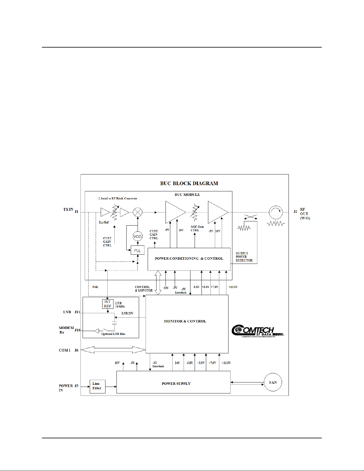
1.4.1 SSPA Block Diagrams
Block diagrams for the LPOD PS-1 and PS-2 SSPAs are shown in Figure 1-2 and Figure 1-3.
The major components of an LPOD unit are:
• SSPA Module
• Cooling System
• Monitor and Control (M&C)
• Power Factor Corrected Power Supply
Figure 1-2. LPOD PS-1 Block Diagram
1–4
Page 19
LPOD C-/Ku-Band Outdoor Amplifier / Block Up Converter (BUC) Revision 0
Introduction MN-LPOD
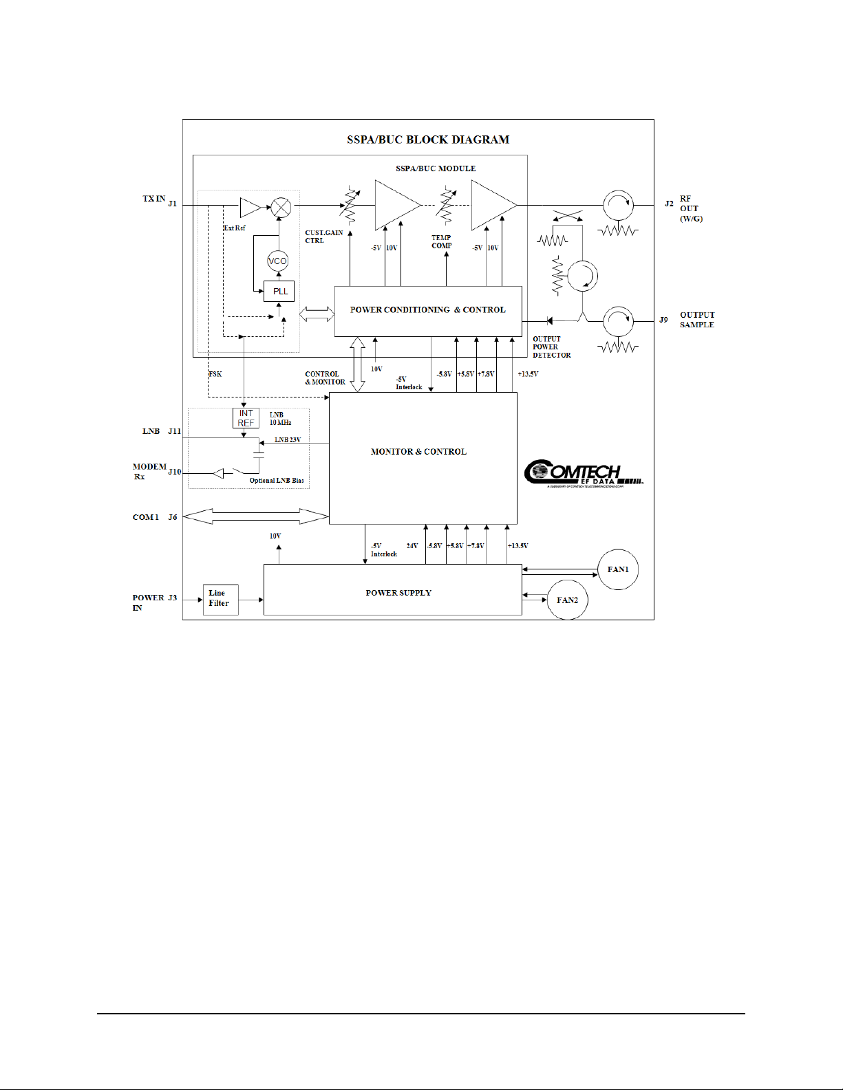
1.4.2 SSPA Module
The amplifier module performs the core function of the unit. An isolator is at the RF input to
ensure good voltage standing wave ratio (VSWR). The RF signal then passes through an
electronically controlled attenuator that adjusts the overall attenuation according to the user input.
After some amplification, a second attenuator is automatically controlled via a look-up table to
maintain the amplifier gain at a constant level over temperature variations.
The RF signal is then amplified by a multi-stage design that utilizes proprietary combining
techniques to meet the rated power requirements. The output circuitry contains a coupler to
provide a sampled signal for monitoring purposes. A power detector circuit also is included and
the reading can be accessed via remote communication. A high power circulator and load is
located at the output to provide good VSWR and protection from external mismatch.
Figure 1-3. LPOD PS-2 Block Diagram
1–5
Page 20

LPOD C-/Ku-Band Outdoor Amplifier / Block Up Converter (BUC) Revision 0
Introduction MN-LPOD
1.4.3 Cooling System
The LPOD contains a robust heat sink and thermal design to maintain a low operating
temperature. The LPOD PS-1 contains one fan that is always on, and the LPOD PS-2 contains
two temperature-controlled fans that are monitored by the M&C board. The fans draw cool
outside air in across the power supply and specialized heat sink. The amplifier module
temperature is monitored and, if for any reason the amplifier temperature exceeds a safe preset
limit, the amplifier module supply is shut down to protect the unit from thermal failure.
1.4.4 Monitor and Control (M&C)
The LPOD includes a microprocessor-based system that provides monitoring and control of the
essential parameters of the unit. The user interfaces with the unit through the M&C system via the
remote control/discrete communications port. The unit is capable of either RS-232, RS-485, or
Ethernet remote communication. A discrete mute control and relay status output is also available.
The M&C system monitors the fan speed (PS-2 only), unit temperature, all power supply
voltages, power transistor currents, output power, etc. Should a critical monitored parameter fail,
the unit will mute the RF signal and report a fault. The details of the fault can be accessed via
remote communication.
The M&C is also capable of acting as a controller in a 1:1 redundant system. When configured as
the back-up SSPA in such a system, it communicates with the other SSPA and toggles the
waveguide switches as necessary.
1.4.5 LNB Operation
Either LPOD package style may be ordered with an optional internal 10MHz reference and Low
Noise Block (LNB) converter bias tee. With these options installed, the user has control of the
bias tee enable (LNB On/Off) as well as the DC bias voltage (On/Off).
1.4.6 Power Supply
The LPOD features a power supply that is power factor corrected. It supplies several voltages
necessary for the unit to operate. The output state of the 10V power supply is controlled by
circuitry within the RF module. If the RF module does not have the –5.8V supply for any reason,
it will not allow the 10V power supply to turn on. This protects the power transistors within the
RF module from failure due to improper power supply sequencing. The +24V output powers the
cooling fans, is the source of power for waveguide switching when the SSPA is used in redundant
configurations, and is dropped to +22V for LNB bias. The +5.8V, -5.8V, +7.8V and +13.5V are
used to operate the M&C board and other overhead functions.
1–6
Page 21

LPOD C-/Ku-Band Outdoor Amplifier / Block Up Converter (BUC) Revision 0
Introduction MN-LPOD
1.4.7 Block Up Converter (BUC) Input
The LPOD translates an L-Band input carrier to the desired output frequency (C-, X-, or KuBand). LO frequencies are as follows:
BUC C, X, Ku, Ka LO Frequencies
Band Frequency LO Frequency Inverting
C-Band 5850 to 6650 MHz 4900 MHz No
X-Band 7900 to 8400 MHz 6950 MHz No
Ku-Band-W 13.75 to 14.50 GHz 12.800 GHz No
Unlike most BUCs, no DC bias voltage should be provided on the center conductor of the L-Band
coax. In addition, the LPOD is available with an internal 10 MHz reference. As, such, no 10 MHz
reference is required on the center conductor of the L-Band coax. If a reference is provided on the
coax, the internal reference will detect and lock to it.
1–7
Page 22

LPOD C-/Ku-Band Outdoor Amplifier / Block Up Converter (BUC) Revision 0
1
Note 2
Introduction MN-LPOD
1.5 Summary of Specifications
1.5.1 Characteristics
IF Input Frequency
Note
RF Output Frequency
950 – 1525 MHz 5.850 – 6.425 GHz
950 – 1750 MHz 5.850 – 6.650 GHz (optional)
950 – 1825 MHz 5.850 – 6.725 GHz (optional)
950 – 1450 MHz 14.00 – 14.50 GHz
950 – 1750 MHz 13.75 – 14.50 GHz (optional)
Model Psat (Typical) P1dB (Guaranteed)
Gain Min (Typical)
PS-1-20Ku 43 dBm (20W) 42 dBm (16W) 70 (75dB)
PS-1-32Ku 43 dBm (32W) 44 dBm (25W) 70 (75dB)
PS-1-32C 45 dBm (32W) 44 dBm (25W) 70 (75dB)
PS-1-50C 47 dBm (50W) 46 dBm (40W) 70 (75dB)
PS-2-125C 51 dBm (125W) 50 dBm (100W) 70 (75dB)
PS-2-150C 52 dBm (150W) 51 dBm (125W) 70 (75dB)
PS-2-200C 53 dBm (150W) 52.5 dBm (175W) 70 (75dB)
PS-2-250C 54 dBm (250W) 53 dBm (200W) 70 75dB)
Notes:
1. PS-2 Models available as SSPAs only, without internal Lband BUC (Freq RF in = Freq RF out).
2. Allow 1 dB degradation from 13.75 to 14.0 GHz and 6425 to 6650 MHz.
Input Power Supply Requirements
90-264 VAC, 47-63 Hz, Power Factor Corrected, .96
(48 VDC optional)
Model P typical, W P Max, W
PS-1-20Ku 200W 210W
PS-1-32Ku 220W 260W
PS-1-32C 200W 220W
PS-1-50C 270W 300W
PS-2-125C 750W 950W
PS-2-150C 800W 1000W
PS-2-200C 950W 1400W
PS-2-250C 1000W 1500W
Max IF Input level (no damage)
Gain Adjust
Gain Flatness
Gain variation over temp
Input Return Loss
Output Return Loss
Noise Figure
RF Mute Isolation
+10 dBm
20 dB in 0.25 dB steps
± 1.5 dB full band (± 1.0 dB PS-2 configured as SSPA only)
± 0.30 dB per 40 MHz
±1.5 dB max, -40 to +55 °C (±1.25 dB, -40 to +60 °C)
15 dB (19.1 dB PS-2 configured as SSPA only)
19.1 dB (1.25:1 VSWR)
10-15 dB typ, 20 dB max @ min. attenuation (8 dB typ, 15 dB
max PS-2 configured
-60 dBc min
1–8
Page 23

LPOD C-/Ku-Band Outdoor Amplifier / Block Up Converter (BUC) Revision 0
–
10
8
Introduction MN-LPOD
AM/PM Conversion
3rd Order Intermod. Level
(2 tones, @ -3 dB Total Backoff from P1 dB
(-6 dBc SCL), Δ 1MHz)
Harmonics
Carrier Related In Band
Spurious Level
Non-Carrier Related In
Band
LO Leakage
Linear
Group delay
variation
Parabolic
Ripple
Data Logging Parameters
Phase Noise (dBc/Hz) (with optional internal or
equivalent performance external reference)
100 Hz -79/-76 -72/-69
1 KHz -91/-89 -84/-82
Offset
10 KHz -105/-98 -97/-90
100 KHz -120/-115 -107/-102
1 MHz -132/-132 -115/-115
2° typ., 3.5° max. @ Rated P1dB output power
-30 dBc typ., -25 dBc Guaranteed
-50 dBc @ Prated – 3 dB
-60 dBc min. @ P1dB
-60 dBm max. ( Input Terminated)
-25 dBm max. (Input Terminated)
± 0.03 ns/MHz
±0 .003 ns/MHz2
± 1.0 ns pk-pk
Non-Volatile RAM : Capacity 30 days @ 90 minute intervals.
Includes:
• RF Output Power
• Mute Status
• Heatsink Temperature
• LNB Bias Current
Typical (C/Ku) dBc/Hz Spec (C/Ku) dBc/Hz
1.5.2 Optional Internal Reference
Internal Reference Oscillator Frequency
Frequency Stability
10 MHz (can lock to modem supplied reference over a range
of -5 dBm to +5 dBm at IF Input)
±5 x 10
±1 x 10
1.5.3 Optional LNB Bias / Reference
LNB Bias Voltage
LNB 10 MHz Reference Output Level
LNB Input/Output Return Loss
LNB Input/Output Gain
LNB Input/Output Gain Flatness
LNB input/Output Isolation (Mute condition)
22 ±1V @ 450mA max
0 dBm ±5dB
15 dB
10 dB ± 2 dB (950-1750 MHz)
-1 dB ± 2 dB (optional)
± 1 dB (950-1750 MHz)
55 dB min
1–9
/ day
-
(-40º to 55ºC)
Page 24

LPOD C-/Ku-Band Outdoor Amplifier / Block Up Converter (BUC) Revision 0
Introduction MN-LPOD
1.5.4 Environmental
Temperature
Humidity
Altitude
Shock
1.5.5 Physical
Weight
Dimensions
(excluding connectors)
Connectors
Operating
Storage
PS-1
PS-2
PS-1
PS-2
IF/RF Input
RF Output
LNB Bias
M&C/Ethernet/
Redundancy Switches
-40º to 122ºF (-40º to 55ºC)
-67º to 167ºF (-55º to 75ºC)
100% condensing rain 2” per hour
10,000 AMSL
Normal commercial shipping and handling
17 lbs. (7.71 kg) Nominal
47 lbs (21.32 kg) Nominal
12.65 x 6.26 x 7.37 in. (321.3 x 159 x 187.2 mm) (See Figure 1-4)
8.80 x 9.78 x 16.81 in. (223.5 x 248.4 x 427 mm) (See Figure 1-5)
Type N, female
PS-1/PS-2 Ku-Band: WR75G
PS-1, C-Band: Type N, female
PS-2, C-Band: CPR137G
Type N, Female
19-pin MS style (single integrated cable assembly available,
dependent upon configuration)
1–10
Page 25

LPOD C-/Ku-Band Outdoor Amplifier / Block Up Converter (BUC) Revision 0
Introduction MN-LPOD
1.6 Dimensional Envelopes
Figure 1-4. LPOD PS-1 Dimensional Envelope
1–11
Page 26

LPOD C-/Ku-Band Outdoor Amplifier / Block Up Converter (BUC) Revision 0
Introduction MN-LPOD
Figure 1-5. LPOD PS-2 Dimensional Envelope
1–12
Page 27

CONNECTIONS and OPERATION
2.1 Overview
This chapter summarizes the connectors provided for all necessary external connections between the
LPOD PS-1 (Figure 2-1 TOP) or PS-2 (Figure 2-1 BOTTOM) units and other equipment. Basic
operational information is also provided in Sect.2.3. For a detailed overview on the LPOD’s
operability (via remote M&C commands), refer to Chapter 3. REMOTE CONTROL.
J10 J11 J1 J2 RF Out
Modem Rx LNB L-Band In (Waveguide Intfc)
Power In COM1
J3 J6
J1 J3 J6 J10 J11 J2 RF Out J9
Tx In Power In COM1 Modem Rx LNB (Waveguide Intfc) Output Sample
Chapter 2. SYSTEM
Figure 2-1. LPOD Connectors
(TOP: PS-1 model; BOTTOM: PS-2 model)
2–1
Page 28

LPOD C-/Ku-Band Outdoor Amplifier/Block Up Converter Revision 0
System Connections and Operation MN-LPOD
2.2 Interface Connectors
2.2.1 Connector J1 – RF IN
RF Input connector J1 is a Type ‘N’ female connector. Labeled
“LBAND IN” on the LPOD PS-1 model and “TX IN” on the LPOD
PS-2 model, typical input levels (-30 dBm) depend on desired output
power and unit attenuation. To prevent damage to the LPOD, RF input
levels should not exceed +15 dBm.
PS-1 J1 Conn.
PS-2 J1 Conn.
2.2.2 Connector J2 – RF OUT
WARNING
For safety reasons, never look directly into the waveguide output.
The RF Output connector is a waveguide interface, as shown in Figure 2-1. The type of flange
used depends on the frequency range of the unit, as described in Table 2-1.
Table 2-1. Waveguide Output Flange
Unit Frequency Band Waveguide Flange
C CPR137G (optional Type ‘N’)
X CPR112G
Ku WR75G
2.2.3 Connector J3 – AC Power Mains
For safety reasons, the user must note that the pin assignments for the PS-1
and PS-2 model power connections are not the same. Product damage or
WARNING
For both the LPOD PS-1 and LPOD PS-2 models, the prime power input requirements are as follows:
personal injury may result from not properly reviewing the information in this
section.
• 90-264 VAC
• 47 to 63 Hz
• The power supply is power factor corrected. The total power required from the prime
power supply depends on the model used. Please refer to Sect. 1.5 Summary of
Specifications.
2–2
Page 29

LPOD C-/Ku-Band Outdoor Amplifier/Block Up Converter Revision 0
System Connections and Operation MN-LPOD
2.2.3.1 LPOD PS-1 J3 AC Power Main
The mating connector specification unique to the LPOD PS-1 AC power
interface and the pin assignments (Table 2-2) are as follows:
Mating Connector: CEFD PN CN/MS-STPG03F02 (ITT Cannon
KPT06B-12-35).
Table 2-2. LPOD PS-1 ‘J3 PWR IN’ Pin Assignments
Pin LPOD PS-1 Assignment
A LINE (L1)
B
C
NEUTRAL (L2)
GND
2.2.3.2 LPOD PS-2 J3 AC Power Main
The mating connector specification unique to the LPOD PS-2 AC power
interface and the pin assignments (Table 2-3) are as follows:
Mating Connector: CEFD PN CN/MS-STPG03F07 (ITT Cannon
CA3106E20-19SB).
Table 2-3. LPOD PS-2 ‘J3 PWR IN’ Pin Assignments
Pin LPOD PS-2 Assignment
A GND
B NEUTRAL (L2)
C LINE (L1)
2–3
Page 30

LPOD C-/Ku-Band Outdoor Amplifier/Block Up Converter Revision 0
System Connections and Operation MN-LPOD
2.2.4 Connector J6 – COM1 (Remote Communications and Discrete Control Port)
The COM 1/ Discrete Control connector J6 is the
primary input for controlling and monitoring the
SSPA. It is a 19-pin circular connector, type
MS3112E14-19S. The pinout specification is
contained in Table 2-4.
Mating connector: ITT: KPT06J14-19P or
MS3116J14-19P.
PS-1 J6 Conn.
Pin Name Description
A RS485_+RX
B RS485_-RX
C RS485_+TX
D RS485_-TX
E RS232_RD Pin 3 of DB9 female connector
F Ethernet TX+ Pin 3 of RJ45 female connector
G RS232_TD Pin 2 of DB9 female connector
H Ethernet TX- Pin 6 of RJ45 female connector
J TX/RX Switch Drive 1 Pos Not for customer use
K Gnd Ground (also Pin 5 of DB-9F connector)
L SUMFLT In Open when faulted, else tied to Pin K
M SUMFLT Out When faulted, tied to Pin K, else open
N TX Switch Pos 1 Ind Online/Offline indication
P RX Switch Pos 1 Ind Not for customer use
R +24V Not for customer use
S System Mute Control System muted if customer ties to Pin K
T Switch Common GND rerence for Pin N
U Ethernet RX- Pin 2 of RJ45 female connector
V Ethernet RX+ Pin 1 of RJ45 female connector
PS-2 J6 Conn.
Table 2-4. Connector J6 Pinout
2–4
Page 31

LPOD C-/Ku-Band Outdoor Amplifier/Block Up Converter Revision 0
System Connections and Operation MN-LPOD
2.2.5 Connector J9 – Output Sample (PS-2 Only)
The Output Sample port connector is a Type ‘N’ female connector
available only on the PS-2 model. It provides a nominal -40 dB sample of
the output signal. A calibration label is provided near the connector that
shows the actual coupling values vs. frequency.
2.2.6 Connectors J10 and J11 – Optional Modem Rx and LNB Interfaces
The J10 Modem Rx and J11 LNB port connectors are both
Type ‘N’ female connectors, providing both bias and a
reference signal to a Low Noise Block Converter (LNB), and
passing the LNB’s L-Band output to the modem’s Rx input.
PS-1 Conns. – J10 (left), J11 (right)
PS-2 Conns. – J10 (left), J11 (right)
2.2.7 Ground Connector
A #10-32 stud is provided at the locations shown in Figure 2-2 for connecting a common
chassis ground among equipment.
PS-1 Ground location
Figure 2-2. LPOD Ground Connectors
PS-2 Ground location
2–5
Page 32

LPOD C-/Ku-Band Outdoor Amplifier/Block Up Converter Revision 0
System Connections and Operation MN-LPOD
2.3 Installation of the LPOD
Several kits are available from Comtech EF Data to mount and install standalone or redundant
LPODs, depending on the type of unit ordered and its operational frequency. They include:
• Universal Pole Mounting Kit PL/12319-1
• LPOD PS-1 Single Thread, P/N TBD
• LPOD PS-2 Single Thread, P/N TBD
Refer to Appendix A. REDUNDANCY for the available assembly kit options for 1:1 LPOD
redundancy configurations.
2.3.1 Universal Pole Mounting Kit PL/12319-1
Item No. Part No. Nomenclature QTY
1 Included i n oth er mounti ng kit Bracket, Unistrut (shown for clarity only) 1
2 FP/BR0072 Bracket, Strap Tensioner 1
3 FP/BR0070 Bracket, Strap-Termination Pole Mounting Kit 1
4 FP/BR0071 Bracket, 1 1/4 Strap(trim to required length) 1
5 FP/BR0069 Bracket, Strap-Fixed, Pole Mounting Kit 1
6 HW/M8X1.25X25HEXSS Bolt, Hexhead, M8X1.25X25, SS 2
7 HW/M8FLATSS Washer, Flat, M8 SS, Metric 7
8 HW/M8LOCKSS Washer, Split lock, M8, SS, Metric 7
9 HW/M8SPRINGNUT Springnut, M8 xX 1.25 2
10 HW/M8X1.25MMHEXNUTSS Nut, Hex M8X1.25X16MM, SS 5
11 HW/PIPEBLOCK Pipe, Block 2
Figure 2-3. Universal Pole Mounting Kit, PL/12319-1
2–6
Page 33

LPOD C-/Ku-Band Outdoor Amplifier/Block Up Converter Revision 0
System Connections and Operation MN-LPOD
2.4 Turning on the LPOD
Never turn the unit ON without proper waveguide termination on the J2 “RF
OUTPUT” port. Individuals can be exposed to dangerously high electromagnetic
WARNING
The LPOD does not contain a ‘Power On/Off’ switch. The SSPA is powered ON by connecting
the J3 AC Power connector to the appropriate prime power source. The Mute or Transmit status
of the SSPA will automatically come up in the last stored state (factory default = Transmit on, not
muted).
levels.
2–7
Page 34

LPOD C-/Ku-Band Outdoor Amplifier/Block Up Converter Revision 0
System Connections and Operation MN-LPOD
Notes:
2–8
Page 35

Chapter 3. REMOTE COMMANDS
3.1 Introduction
This section describes the operating features of the LPOD C-/Ku-Band Outdoor Amplifier /
Block Up Converter (BUC). A few key parameters and procedures are summarized, followed by
detailed instructions of remote control communication commands.
3.1.1 RF Input Level
The required RF input level to reach the full rated output power of the SSPA is determined by the
individual amplifier maximum gain and power rating. For example, if the test data of an SSPA rated
for 250W (54 dBm) indicated a gain of 75 dB, then a signal of 54 dBm – 75 dB = -21 dBm would
approximately give the rated output power. Increasing input power beyond this level would result in
an output signal with increasingly higher levels of distortion. Of course, if the LPOD attenuation
control is utilized, a higher level input signal level can be accommod ated. The maximum input level
should never exceed 15dBm, or permanent damage to the unit may occur.
3.1.2 Attenuator Control
The LPOD gain can be attenuated over its specified ra nge by exercising the AT T command. The
details for the format of this command are found later in this chapter.
3.1.3 Mute Control
The LPOD may be muted via software or discrete control. Exercising the MUT=1 command will
“software” mute the unit. The LPOD also may be “hardware” muted by pulling Pin S on the Com
1 / Discrete control connector (J6) to ground (See Chapter 2. SYSTEM CONNECTIONS and
OPERATION).
The Mute command provides over 75 dB of RF on/off isolation. However, the Mute command
only turns off the first few low power stages of the amplifier, the high power stages remain on.
By allowing the higher power transistors to stay on, the LPOD remains in more thermally stable
state should the mute condition be removed.
3–1
Page 36

LPOD C-/Ku-Band Outdoor Amplifier / Block Up Converter (BUC) Revision 0
Remote Commands MN-LPOD
If the user desires to completely turn off the bias to the entire amplifier (perhaps to conserve
energy in a redundant system), both the
normal transmit operation,
MUT=0 and AMP=1 are required.
MUT=1 and AMP=0 commands should be executed. For
3.1.4 Faults
The M&C system monitors certain key functions of the LPOD for proper operation. Should any
of these parameters exceed predetermined limits, the M&C system will declare a fault. The
conditions that trigger a fault are:
• Any power supply more than ± 10% outside its nominal value
• Fan less than 25% of maximum speed (PS-2 Only)
• I2C internal bus communications fault
• Thermal Shutdown - A temperature fault is indicated if the unit is +>90°C. This creates a
summary fault and will cause the unit to mute itself and switch to the back-up unit (if in a
redundant system). However, the 10V supply to the FET transistors will remain on until
the unit reaches the thermal shutdown temperature of ≥ >95°C. For protection reasons,
the unit will shut down the 10V supply to the power transistors at temperatures >95°C.
3.1.5 Power Detector
A power detector is provided to monitor the output power. It has a useful range of over 20 dB,
referenced to the unit’s rated P1dB point, and its value can be read by exercising the
command. The test data supplied with each unit gives an indication of the excellent accuracy and
flatness of the power monitor over the frequency band of operation.
3.1.6 Some Common Commands
A few of the most common commands and queries are listed below. Full details for each of these
are listed at the end of this section.
•
RMS: Retrieve Maintenance Status. Displays voltages, fan speeds, Heatsink temperature,
output power monitor reading, etc.
•
RCS: Retrieve Configuration Status. Displays current attenuation, mute, amplifier,
online, etc. status.
•
RAS: Retrieve Alarm Status. Displays current alarm or fault status.
3.2 Remote Control Protocol and Structure
This section describes the protocol and message command set for remote monitor and control of
the LPOD.
The electrical interface is either an RS-485 multi-drop bus (for the control of many devices) or an
RS-232 connection (for the control of a single device), and data is transmitted in asynchronous serial
form, using ASCII characters. Control and status information is transmitted in packets, of variable
length, in accordance with the struc ture a nd pro tocol define d i n later s ections .
RMS
3–2
Page 37

LPOD C-/Ku-Band Outdoor Amplifier / Block Up Converter (BUC) Revision 0
Remote Commands MN-LPOD
3.2.1 RS-485
For applications where multiple devices are to be monitored and controlled, a full-duplex (or
4-wire) RS-485 is preferred. Half-duplex (2-wire) RS-485 is possible, but is not preferred.
In full-duplex RS-485 communication there are two separate, isolated, independent, differentialmode twisted pairs, each handling serial data in different directions. It is assumed that there is a
‘controller’ device (a PC or dumb terminal), which transmits data, in a broadcast mode, via one of
the pairs. Many ‘target’ devices are connected to this pair, which all simultaneously receive data
from the controller. The controller is the only device with a line-driver connected to this pair – the
target devices only have line-receivers connected.
In the other direction, on the other pair, each target has a tri-stateable line driver connected, and
the controller has a line-receiver connected. All the line drivers are held in high-impedance mode
until one (and only one) target transmits back to the controller.
Each target has a unique address, and each time the controller transmits, in a framed ‘packet’ of
data, the address of the intended recipient target is included. All of the targets receive the packet,
but only one (the intended) will reply. The target enables its output line driver, and transmits its
return data packet back to the controller, in the other direction, on the physically separate pair.
RS-485 (Full Duplex) Summary:
Two differential pairs
Controller-to-target pair
Target-to-controller pair
3.2.2 RS-232
This is a much simpler configuration in which the controller device is connected directly to the
target via a two-wire-plus-ground connection. Controller-to-target data is carried, via RS-232
electrical levels, on one conductor, and target-to-controller data is carried in the other direction on
the other conductor.
3.2.3 Basic Protocol
Whether in RS-232 or RS-485 mode, all data is transmitted as asynchronous serial characters,
suitable for transmission and reception by a UART. The character format should be 8N1 (8 data
bits, no parity, 1 stop bit). The baud rate may vary between 1200 and 38,400 baud.
All data is transmitted in framed packets. The controller is assumed to be a PC or ASCII dumb
terminal, which is in charge of the process of monitor and control. The controller is the only
device that is permitted to initiate, at will, the transmission of data. Targets are only permitted to
transmit when they have been specifically instructed to do so by the controller.
One pair for controller to target, one pair for target to controller.
Pair has one line driver (controller), and all targets have line-
receivers.
Pair has one line receiver (controller), and all targets have tri-state
drivers.
3–3
Page 38

LPOD C-/Ku-Band Outdoor Amplifier / Block Up Converter (BUC) Revision 0
Remote Commands MN-LPOD
All bytes within a packet are printable ASCII characters, less than ASCII code 127. In this
context, the Carriage Return and Line Feed characters are considered printable.
All messages from controller-to-target require a response – with one exception. This will be either to
return data that has been requested by the controller, or to acknowledge reception of an instruction to
change the configuration of the target. The exception to this is when the controller broadcasts a
message (such as Set time/date) using Address 0, when the target is set to RS-485 mode.
3.2.4 Packet Structure
Controller-to-Target:
Start of
Packet
<
ASCII code 60
(1 character)
Target
Address
(4 characters)
Address
De-limiter
/
ASCII code 47
(1 character)
Example: <0412/MUT=1{CR}
Target-to-Controller:
Start of
Packet
>
ASCII code 62
(1 character) (4 characters)
Target
Address
Address
De-limiter
/
ASCII code 47
(1 character) (3 characters)
Example: >0412/MUT=1{CR}{LF}
3.2.4.1 Start of Packet
¾ Controller-to-Target: This is the character '<' (ASCII code 60)
Instruction
Code
(3 characters)
Instruction
Code
Code
Qualifier
= or ?
ASCII codes
61 or 63
(1 character)
Code
Qualifier
=, ?, !, or *
ASCII codes
61,63,33 or 42
(1 character)
Optional
Arguments
(n characters)
Optional
Arguments
(From 0 to n
characters)
End of
Packet
Carriage Return
ASCII code 13
(1 character)
End of
Packet
Carriage Return,
Line Feed
ASCII codes
13,10
(2 characters)
¾ Target-to-Controller: This is the character '>' (ASCII code 62)
Because this is used to provide a reliable indication of the start of packet, these two characters
may not appear anywhere else within the body of the message.
3.2.4.2 Address
Up to 9,999 devices can be uniquely addressed. In RS-232 applications this value is set to 0. In
RS-485 applications, the permissible range of values is 1 to 9999. It is programmed into a target
unit using the front panel keypad.
The controller sends a packet with the address of a target – the destination of
the packet. When the target responds, the address used is the same address, to
IM PORTANT
indicate to the controller the source of the packet. The controller does not have
its own address.
3–4
Page 39

LPOD C-/Ku-Band Outdoor Amplifier / Block Up Converter (BUC) Revision 0
Remote Commands MN-LPOD
3.2.4.3 Instruction Code
This is a three-character alphabetic sequence that identifies the subject of the message. Wherever
possible, the instruction codes have been chosen to have some significance. For example: GAC
for Glocal Amplifier Configuration; IPA for IP Address, etc. This aids in the readability of the
message, should it be displayed in its raw ASCII form. Only upper case alphabetic characters
may be used (A-Z, ASCII codes 65 - 90).
3.2.4.4 Instruction Code Qualifier
This single character further qualifies the preceding instruction code. Code Qualifiers obey the
following rules:
1. From Controller-to-target, the only permitted values are:
=
(ASCII code 61
?
(ASCII code 63)
The = (ASCII code 61) is used as the assignment operator, and is used to
indicate that the parameter defined by the preceding byte should be s et to the
value of the argument(s) that follow it. For example: In a message from
controller-to-target, MUT=1 would mean ‘enable the Mute function’.
The ? (ASCII code 63) is used as the query operator, and is used to indicate that
the target should return the current value of the parameter defined by the
preceding byte. For example: In a message from controller-to-target, SWR?
would mean ‘returns the value of the internal so ftw are revision in stalled in the uni t’.
2. From Target-to-controller, the only permitted values are:
=
(ASCII code 61)
?
(ASCII code 63)
The = code is used in two ways:
First, if the controller has sent a query code to a target ( for example: MUT?,
meaning ‘is the Mute enabled or disabled?’), the target would respond with
MUT=x, where x represents the state in question: 1 being ‘enable’ and 0 being
‘disable’.
Second, if the controller sends an instruction to set a parameter to a particular
value, and if the value sent in the argument is valid, then the target will
acknowledge the message by replying with MUT= (with no message arguments).
The ? code is only used as follows:
If the controller sends an instruction to set a parameter to a particular value,
then, if the value sent in the argument is not valid, the target will acknowledge
the message by replying, for example, with MUT? (with no message arguments).
This indicates that there was an error in the message sent by the controller.
!
(ASCII code 33)
*
(ASCII code 42)
The ! code is only used as follows:
If the controller sends an instruction code which the target does not rec ognize,
the target will acknowledge the message by echoing the invalid instruction,
followed by the ! character. Example: XYZ!
The * code is only used as follows:
If the controller sends an instruction to set a parameter to a particular value,
then, if the value sent in the argument is valid, BUT the target is in the wron g
mode (e.g., standy mode in redundancy conf iguration) and willl not permit that
particular parameter to be changed at that time, the target will acknowledge the
message by replying, for example, with MUT* (with no message arguments).
3–5
Page 40

LPOD C-/Ku-Band Outdoor Amplifier / Block Up Converter (BUC) Revision 0
Remote Commands MN-LPOD
#
(ASCII code 35)
The # code (target-to-controller) is only used as follows:
If the controller sends an instruction code which the target cannot currently
perform because of hardware resource issues, then the target will acknowledge
the message by echoing the invalid instruction, followed by the # c haracter. This
response can only occur if the operator sends two or more ‘hardware
configuration’ type commands without allowing adequate time between
commands for the hardware to be configured. For example, if the operator
issued commands to change both the frequency and the attenuation with les s
than 100 milliseconds between commands, and if this response is returned,
then the command has not been accepted and the operator must resend the
command.
3.2.4.5 Message Arguments
Arguments are not required for all messages. Arguments are ASCII codes for the characters 0 to 9
(ASCII 48 to 57); period (ASCII 46); and comma (ASCII 44).
3.2.4.6 End of Packet
Controller-to-target: This is the 'Carriage Return' character (ASCII code 13).
Target-to-controller: This is the two-character sequence 'Carriage Return' (ASCII code 13), and
'Line Feed' (ASCII code 10).
Both indicate the valid termination of a packet.
3.2.4.7 End-of-Life Commands
Certain commands (denoted by an * in the Parameter Type field) are being marked as EOL.
While these commands are fully supported in this product, it is highly recommended that the
equivelant new commands be used for new implementations. The new commands will generally
follow the outdated commands.
3–6
Page 41

LPOD C-/Ku-Band Outdoor Amplifier / Block Up Converter (BUC) Revision 0
X
X
X
X
X
X
X
X
X
X
X
X
X
X
X
X
X
X
X
X
2
X
X
X
X
X
X
X
X
X
X
X
X
X
X
X
X
X
X
X
V
K
X
2
X
X
X
X
X
X
X
X
X
X
X
X
X
X
X
X
X
X
X
Remote Commands MN-LPOD
3.3 Remote Commands and Queries
Column ‘C’ = Command; Column ‘Q’ = Query; columns marked ‘X’ designate instruction code as Command only, Query only, or Command/Query.
2
Where an Instruction Code is noted XXX
CODE C Q PAGE CODE C Q PAGE CODE C Q PAGE CODE C Q PAGE
A
AFR
AMP
AOF2
ATT
AUX
B
C
CAA
CAE
CAS
CCS
CDS
CFS
CID
CLC
CMS
CUS
CWE
D
DAT
DAY
E
ESA2
ESL2
ESW2
X X
X X
X X
X X
X X
3-8 FRW
3-27 MSK
3-8 MUT
3-8
3-9 GAC
NUE
SSI
X
X
X
X
X X
X
X X
X X
X
X
X X
3-9 SWR
3-9
3-10 IEP
3-11 IMG
3-15 IPA
3-15 IPG
3-9 ISP2
3-12
3-15
3-16 RAS X3-20
3-13 RBT X3-30
RED
X X
X X
3-28 REF
3-28
LCS
LCW
X X
X X
X X
3-33 LNA
3-33 LPT
3-18 LRS
this denotes a Phase 2 Release command.
F
M
3-22 MAC
G
SBR
3-11 SBT
N
H
I
NUS2
O
3-26 ONL2
3-16 TIM
3-16 TMP
3-16
P
3-32 PNM
J
RCS
R
L
RET X3-21
3-12 RFS
3-13 RLC2
3-24 RMS
3-14 RNE
XX
3-17 RNS
2
X
RSN
3-30 RUS
X
3-27
3-26
3-31
3-17
S
3-19
3-29
SFS
3-26 SNO
3-32 SPA
3-29
3-28
3-18
3-33
3-12
3-17
T
3-28
3-24
TNA
3-17 TSC
U
3-26
3-30
3-21
3-18
W
3-18
3-27 XRM
3-29
3-13
3-23
Y
3-25
3-31
Z
3–7
Page 42

LPOD C-/Ku-Band Outdoor Amplifier / Block Up Converter (BUC) Revision 0
Remote Commands MN-LPOD
*Note (where Parameter Type is prefixed with *): While the underlying command will remain, the specific functionality will be obseleted, and
should not be used for new implementations. There generally will be a different command elsewhere that encapsulates the marked functionality.
Command
Parameter Type
Attenuation ATT= 5 bytes Command or Query.
Attenuation Offset
Phase 2 Release
Auto Fault
Recovery
(Instruction
Code and
Qualifier)
AOF= 5 bytes Command or Query.
AFR= 1 byte Command or Query.
Arguments for
Command or
Response to
Query
(Note that all arguments are ASCII numeric codes: i.e.,
Description of arguments
ASCII codes between 48 and 57)
Valid attenuation level (00.00 to 20.00), in dB, in 0.25
dB steps as factory default.
Example: <1/ATT=12.25’cr’
>0001/ATT=’cr’’lf’
Default Value: 00.00
Valid attenuation level (00.00 to 20.00), in dB, in 0.25
dB steps as factory default. This value is not copied to
the offline unit in a redundant system, but will be
added to the attenuation value upon a switchover. This
provides a unit specific fine-tune to maintain power
levels appropriately in a redundant system.
Example: <1/AOF=12.25’cr’
>0001/AOF=’cr’’lf’
Default Value: 00.00
The LPOD output will automatically be muted in the
event of detected fault. If auto fault recovery is
enabled, it will cause the output return to its pre-fault
mute condition if all faults are cleared. If disabled, the
output will remain muted even if all faults are cleared.
Example: <1/AFR=1’cr’
>0001/AFR=’cr’’lf’
Default Value: 1
Response to
Command
(Target to controller)
ATT= (message ok)
ATT? (Received ok, but
invalid arguments
found)
ATT* (message ok, but
not permitted in current
mode)
AOF= (message ok)
AOF? (Received ok, but
invalid arguments
found)
AOF* (message ok, but
not permitted in current
mode)
AFR = (message ok)
AFR? (received ok, but
invalid arguments
found)
AFR* (message ok, but
not permitted in current
mode)
Query
(Instruction
Code and
qualifier)
ATT? ATT=xx.xx
AOF? AOF=xx.xx
AFR? AFR=x
Response to
query
(Target to
controller)
(Same format as
command
arguments.)
(Same format as
command
arguments.)
(Same format as
command
arguments.)
3–8
Page 43

LPOD C-/Ku-Band Outdoor Amplifier / Block Up Converter (BUC) Revision 0
Remote Commands MN-LPOD
Parameter Type
Auxiliary Mute
Enable
Circuit
Identification
*Clear All Stored
Alarms
Clear All Stored
Events
Command
(Instruction
Code and
Qualifier)
AUX= 1 byte Command or Query.
CID= 24 bytes
CAA= None Command only.
CAE= None Command only.
Arguments for
Command or
Response to
Query
(Note that all arguments are ASCII numeric codes: i.e.,
Description of arguments
ASCII codes between 48 and 57)
Enables or disables the auxiliary mute mode.
0=Disabled
1=Enabled
Example (AUX Mute Enabled): AUX=1’cr’
Note: When enabled, the mute contol input on the
remote com connector must be grounded to UN-MUTE
the unit. Otherwise, the unit will be muted, and if a
mute query is given (MUT?) the response will be
MUT=2 to indicate a hardware controlled mute is
present.
Default Value: 1
Command or Query.
CID is a user-defined string of data that may be used
to identify or name the unit or station. The CID is a 24byte field of data that is entered as one line, but it will
be read back from the unit as two 12-byte lines of data.
Examples:
<1/CID= Station #001--SSPA #01--’cr’
>0001/CID=
<1/CID?’cr’
>0001/CID=’cr’
Station #001’cr’
--SSPA #01--’cr’’lf’
Default Value: -----------------------Instructs the LPOD to clear all Stored Alarms. This
command takes no arguments.
Example: <1/CAA=’cr’
>0001/CAA=’cr’’lf’
Instructs the SSPA to clear all Stored Events. This
command takes no arguments.
Example: <1/CAE=’cr’
>0001/CAE=’cr’’lf’
Response to
Command
(Target to controller)
AUX= (message ok)
AUX? (received ok, but
invalid arguments
found)
AUX* (message ok, but
not permitted in current
mode)
CID= (message ok)
CID? (received ok, but
invalid arguments
found)
CAA= (message ok)
CAE= (message ok)
Query
(Instruction
Code and
qualifier)
AUX? AUX=x
CID? CID=x…x
N/A
N/A
Response to
query
(Target to
controller)
(Same format as
command
arguments.)
(See description
for details of
arguments.)
N/A
N/A
3–9
Page 44

LPOD C-/Ku-Band Outdoor Amplifier / Block Up Converter (BUC) Revision 0
Remote Commands MN-LPOD
Parameter Type
Concise Alarm
Status
Command
(Instruction
Code and
Qualifier)
N/A 44 bytes
Arguments for
Command or
Response to
Query
(Note that all arguments are ASCII numeric codes: i.e.,
Description of arguments
ASCII codes between 48 and 57)
Query only.
Used to Query the Alarm status of the unit, response is
semicolon delimited. This is the concise version of the
RAS command.
Example:
CAS=a;b;c;d;e;f;g;h;I;j;k;I;m;n;o;p;q;r;s;t;u;v;’cr’’lf’
Where:
a thru s = 0, 1, or 2,
0 = FT, 1 = OK, 2 = AL, 3 = NO, 4 = YS, 5 = MS
a = +24V Power Supply
b = +24V Switch Power Supply
*c = +13/18V LNB Power Supply
d = +13.5V Power Supply
e = +10V Power Supply
*f = +10V2 Power Supply
g = +5.8V Power Supply
h = +2.5V Power Supply
i = +1.2V Power Supply
j = -5.8V Power Supply
k = Fan#1 State
*l = Fan#2 State
m = Heatsink Temp
n = Overtemp Shutdown
o = llC Status
p = Forward Power Alarm
q = Flash Checksum
r = FPGA Done
*s = BUC Lock Detect
*t = External Ref Lock Detect
*u = LNB Current
*v = Redundant Switch Condition
*Note: c, f, l, s, t, u, and v will appear if the appropriate
model/options have been selected/installed.
Response to
Command
(Target to controller)
N/A CAS?
Query
(Instruction
Code and
qualifier)
Response to
query
(Target to
controller)
CAS=x….x
(See description
for details of
arguments)
3–10
Page 45

LPOD C-/Ku-Band Outdoor Amplifier / Block Up Converter (BUC) Revision 0
Remote Commands MN-LPOD
Parameter Type
Concise
Configuration
Status
Global Amplifier
Configuration
Command
(Instruction
Code and
Qualifier)
N/A 26 bytes Query only.
GAC= 43 bytes Command or Query.
Arguments for
Command or
Response to
Query
(Note that all arguments are ASCII numeric codes: i.e.,
ASCII codes between 48 and 57)
Used to query the configuration status of the unit. This
is the concise version of the RCS command.
Where:
aa.aa = attenuation in dB (ATT)
b = RF power amplifier state, 0 = Off, 1 = On (AMP)
c = mute state, 0 = un-muted, 1 = muted (MUT)
d = online status (ONL)
e = redundancy state and mode (ESW)
ff.ff = Attenuator offset in dB (AOF)
g = auto fault recovery mode (AFR)
*hhh = External reference status, N/A = no external
reference, 05M for 5 MHz, and 10M for a 10 MHz
*Note: hhh will always be N/A if the internal reference
oscillator option is not installed.
Used to set up and query the global status of the
BUC/SSPA with a semicolon delimited string of data.
Example (set GAC):
GAC=a;b;cc.cc;dd.dd;e;fffff;g;hh;I;j;k;l;m;n;o;’cr’
Where:
a = redundancy mode (ESW)
b = online status (ONL)
cc.cc = Attenuation Offset (AOF)
dd.dd = Customer Attenuation(ATT)
e = Auto Fault Recovery (AFR)
fffff = Unit Alarm Mask (MSK)
g = LNB Current Source (LCS)
hh = LNB Current Window (LCW)
i = LNB Current Window Enable (CWE)
j = Enable Statistics Averaging (ESA)
k = Set Statistics Interval (SSI)
l = Enable Statistics Logging (ESL)
m = Auxilary Mute (AUX)
n = user mute state (MUT)
o = RF power amplifier state (AMP)
Description of arguments
Response to
Command
(Target to controller)
N/A CCS? CCS=x….x
N/A GAC? GAC=x….x
Query
(Instruction
Code and
qualifier)
Response to
query
(Target to
controller)
(See description
for details of
arguments)
(See description
for details of
arguments)
3–11
Page 46

LPOD C-/Ku-Band Outdoor Amplifier / Block Up Converter (BUC) Revision 0
Remote Commands MN-LPOD
Parameter Type
Software
Revision
Calibrate LNB
Current
LNB Current
Source
Command
(Instruction
Code and
Qualifier)
N/A 34-37 bytes Query only.
CLC= none Command or Query.
LCS= 1 byte Command or Query.
Arguments for
Command or
Response to
Query
(Note that all arguments are ASCII numeric codes: i.e.,
ASCII codes between 48 and 57)
Unit returns the value of the internal software revision
installed in the unit, in the form:
Boot:x.y.z Bulk1:x.y.z Bulk2:x.y.z
-orBoot:x.y.zz Bulk1:x.y.zz Bulk2:x.y.zz
The CLC command stores the value of the LNB
Current Supply (in mA) as a reference point. The LNB
current alarm point is then based on this point +/- the
LCW setting.
Note: this command will return a mode error if the LCS
output has not been enabled first.
Example: <1/CLC=’cr’
>0001/CLC=’cr’’lf’
The CLC query will return the value that was stored
during the LNB current calibration.
Example: <1/CLC?’cr’
>0001/CLC=xxx.x
Where:
xxx.x is the calibrated LNB current value in mA.
This command enables, or disables the LNB current
source. Note: LCS must be enabled before the LNB
current can be calibrated with the CLC command.
0 = Disable
1 = Enable
Example: <1/LCS=1’cr’
>0001/LCS=’cr’’lf’
Default Value: 0
Description of arguments
Response to
Command
(Target to controller)
N/A SWR? SWR=Boot:x.y.zz
CLC=(message ok)
CLC?(received ok, but
invalid arguments
found)
CLC*(message ok, but
not permitted in current
mode)
LCS=(message ok)
LCS?(received ok, but
invalid arguments
found)
LCS*(message ok, but
not permitted in current
mode)
Query
(Instruction
Code and
qualifier)
CLC? CLC=xxx.x
LCS? LCS=x
Response to
query
(Target to
controller)
Bulk1:x.y.zz
Bulk2:x.y.zz
(See description
of arguments)
(See description
of arguments)
(Same format as
command
arguments)
3–12
Page 47

LPOD C-/Ku-Band Outdoor Amplifier / Block Up Converter (BUC) Revision 0
Remote Commands MN-LPOD
Parameter Type
Remote LNB
Control
Phase 2 Release
LNB Current
Window
LNB Current
Window Enable
Command
(Instruction
Code and
Qualifier)
Arguments for
Command or
Response to
Query
(Note that all arguments are ASCII numeric codes: i.e.,
ASCII codes between 48 and 57)
RLC= 1 byte Command or Query.
This command configures the control features of the
LNB:
0: 22kHz disabled, 13V
1: 22kHz enabled, 13V
2: 22kHz disabled, 18V
3: 22kHz enabled, 18V
Others: Reserved
Example: <1/LDC=0’cr’
>0001/LDC=’cr’’lf’
Default Value: 0
LCW= 2 bytes Command or Query.
This command allows the user to set the alarm window
in ± % of the calibrated LNB Current. Valid inputs are
20 to 50 in increments of 1%. In addition, setting the
value to 99
1
disables the alarm function.
*Note: A return value of 99 indicates that the current
window is disabled. This may be because a value of
99 was set for LCW, or it may be because the CWE
has been disabled. Since the method of setting 99 to
this command is being obsoleted, it is recommended
the user utilize CWE instead of 99.
The following example will set the alarm window to
±30%.
Example: <1/LCW=30’cr’
>0001/LCW=’cr’’lf’
Default Value: 30
CWE= 1 bytes Command or Query.
This command allows the user to enable the current
window alarm alarm. If disabled, the LCW value will be
retained, but unused.
Example: <1/CWE=0’cr’
>0001/CWE=’cr’’lf’
Default Value: 0
Description of arguments
Response to
Command
(Target to controller)
RLC =(message ok)
RLC?(received ok, but
invalid arguments
found)
RLC *(message ok, but
not permitted in current
mode)
LCW= (message ok)
LCW? (received ok, but
invalid arguments
found)
LCW* (message ok, but
not permitted in current
mode)
CWE = (message ok)
CWE? (received ok, but
invalid arguments
found)
CWE * (message ok,
but not permitted in
current mode)
Query
(Instruction
Code and
qualifier)
Response to
query
(Target to
controller)
RLC? RLC =x
(Same format as
command
arguments)
LCW? LCW=xx
(Same format as
command
arguments)
CWE? CWE =x
(Same format as
command
arguments)
3–13
Page 48

LPOD C-/Ku-Band Outdoor Amplifier / Block Up Converter (BUC) Revision 0
Remote Commands MN-LPOD
Parameter Type
Low forward
Power Threshold
Command
(Instruction
Code and
Qualifier)
LPT= 5 bytes Command or Query.
Arguments for
Command or
Response to
Query
(Note that all arguments are ASCII numeric codes: i.e.,
ASCII codes between 48 and 57)
This command allows the user to set the threshold for
the low forward power alarm/fault. If the forward power
drops below the specified value, the alarm/fault will be
indicated. Setting this parameter to 000.0 effectively
disables the threshold
Example: <1/LPT=000.0’cr’
>0001LPT=’cr’’lf’
Default Value: 000.0
Description of arguments
Response to
Command
(Target to controller)
LPT = (message ok)
LPT? (received ok, but
invalid arguments
found)
LPT * (message ok, but
not permitted in current
mode)
Query
(Instruction
Code and
qualifier)
LPT? LPT =xxx.x
Response to
query
(Target to
controller)
(Same format as
command
arguments)
3–14
Page 49

LPOD C-/Ku-Band Outdoor Amplifier / Block Up Converter (BUC) Revision 0
Remote Commands MN-LPOD
Parameter Type
Concise
Maintenance
Status
Concise RF
Power FET
Current Status
Command
(Instruction
Code and
Qualifier)
N/A 95 bytes
N/A Variable length
Arguments for
Command or
Response to
Query
depending on the
number of FETs
installed in the
amplifier
(Note that all arguments are ASCII numeric codes: i.e.,
Description of arguments
ASCII codes between 48 and 57)
Query only.
Used to Query the Maintenance status of the unit in a
concise format. The response is semicolon delimited.
This is the concise version of the RMS command.
Example:
<1/CMS?
>0001/CMS=aaa.a;bbb.b;ccc.c;ddd.d;eee.e;fff.f;
ggg.g;hh.h;iii.i;jjj.j;kkk.k;lll.l;mmm.m;
nnn.n;ooo.o;ppp.p;qqq.q;’cr’’lf’
Where:
aaa.a = P24V1
bbb.b = P24V2
*ccc.c = LNBVT
ddd.d = P13VT
eee.e = A10V1
*fff.f = A10V2
ggg.g = P7V8T
hhh.h = P5V8T
iii.i = P2V5T
jjj.j = P1V2T
kkk.k = N5V8T
*lll.l = FANR1
*mmm.m = FANR2
*nnn.n = BUCVT
ooo.o = FWPWR
*ppp.p = REFVT
*qqq.q = LNBCS
rrr.r = ATEMP
*Note: ccc.c, fff.f, lll.l, mmm.m, nnn.n, and ppp.p, and
qqq.q will appear if the appropriate model/options have
been selected/installed.
Query only
Concise version of RFS.
Example: CFS=xxx,xxx,x.x,x.x,……….,x.x,
Response to
Command
(Target to controller)
N/A CMS?
N/A CFS? CFS=x…..x
Query
(Instruction
Code and
qualifier)
Response to
query
(Target to
controller)
CMS=x….x
(See description
for details of
arguments)
(See description
of RFS. Note that
each argument is
separated by a
comma.)
3–15
Page 50

LPOD C-/Ku-Band Outdoor Amplifier / Block Up Converter (BUC) Revision 0
Remote Commands MN-LPOD
Command
Parameter Type
*Concise Utility
Status
Software Image IMG= 1 byte
IP Address IPA= 18 bytes Command or Query.
Gateway Address IPG= 15 bytes Command or Query.
(Instruction
Code and
Qualifier)
N/A 15 bytes
Arguments for
Command or
Response to
Query
(Note that all arguments are ASCII numeric codes: i.e.,
Description of arguments
ASCII codes between 48 and 57)
Query only.
Used to Query the Maintenance status of the unit,
response is comma delimited.
Example:
<1/CUS?’cr’>0001/CUS=aaaa;bbbbb;ccc;’cr’’lf’
Where:
aaaa = Remote Unit Address
bbbbb = Remote Baud Rate
*ccc = Reference oscillator tuning voltage
DAC value
*Note: ccc is only present if a reference oscillator is
installed.
Command or Query.
Current Active software image, where:
1=Bulk Image # 1 currently active
2=Bulk Image # 2 currently active
Example: IMG=1 (which is Image #1 active)
Used to set the IP address and network prefix for the
10/100 BaseT Ethernet management port, in the
format:
xxx.xxx.xxx.xxx.yy, where:
xxx.xxx.xxx.xxx is the IP address, and
yy is the network prefix (8-30)
Example: 192.168.001.004.24
Default Value: 192.168.001.004.24
Used to set the Gateway IP addess for the 10/100
Base Tx Ethernet management port, in the format:
xxx.xxx.xxx.xxx, where:
xxx.xxx.xxx.xxx is the IP address
Example: IPG = 192.168.001.005
Default Value: 192.168.001.005
Response to
Command
(Target to controller)
N/A CUS?
IMG=
IMG?
IMG*
IMG#
IPA=
IPA?
IPA*
IPA#
IPG= (message ok)
IPG? (received ok, but
invalid arguments
found)
IPG * (message ok, but
not permitted in current
mode
Query
(Instruction
Code and
qualifier)
IMG?
IPA? IPA=
IPG? IPG =
Response to
(Target to
controller)
CUS=x….x
(See description
for details of
arguments)
IMG=x
(See description
of arguments)
xx.xxx.xxx.xxx.yy
(See description
of arguments)
xxx.xxx.xxx.xxx
query
3–16
Page 51

LPOD C-/Ku-Band Outdoor Amplifier / Block Up Converter (BUC) Revision 0
Remote Commands MN-LPOD
Command
Parameter Type
Local/Remote
State
Mute State MUT= 1 byte Command or Query.
Part Number N/A Various 1-96
*Online Status
Phase 2 Release
(Instruction
Code and
Qualifier)
LRS= 1 byte Command or Query.
ONL= 1 byte Command or Query.
Arguments for
Command or
Response to
Query
bytes
(Note that all arguments are ASCII numeric codes: i.e.,
ASCII codes between 48 and 57)
Set Local or Remote for Indoor SSPA. Always in
remote mode for Outdoor SSPA
0 = Local, 1=Serial, 2=Ethernet
Example: LRS=1
*Note: The customer will always have query access in
either mode. Also, the LRS command is available in all
modes as a means of acquiring control. The intent of
this command is to limit changes from being made on
multiple interfaces at the same time. Units without a
front panel will treat an entry of 0 as reserved, and will
refuse the command by returning a mode error .
Mute the unit, where:
0 = Disable (Not Muted)
1 = Enable (Muted)
2 = Unit muted due to AUX mute signal. This value is
only shown in the response to a query, and cannot be
given as a command.
Example: <1/MUT=1’cr’
>0001/MUT=1’cr’’lf’
Default Value: 1
Query only.
Returns the Comtech EF Data part number of the unit.
This part number is the unit’s DOTCODE at the time it
was manufactured. The DOTCODE may be up to 96
printable ASCII characters long.
Example: <1/PNM?’cr’
>0001/PNM=HPODC0.350WRSW00’cr’’lf’
Online status (applies only to redundancy), where:
0 = Offline
1 = Online
Example: <1/ONL=1’cr’
>0001/ONL=’cr’’lf’
Description of arguments
Response to
Command
(Target to controller)
LRS= (message ok)
LRS? (received ok, but
invalid arguments
found)
MUT= (message ok)
MUT? (received ok, but
invalid arguments
found)
MUT* (message ok, but
not permitted in current
mode)
N/A PNM? PNM=x….x
ONL= (message ok)
ONL? (Received ok, but
invalid arguments
found)
ONL* (message ok, but
not permitted in current
mode)
Query
(Instruction
Code and
qualifier)
LRS? LRS=x
MUT? MUT=x
ONL? ONL=x
Response to
query
(Target to
controller)
(Same format as
command
arguments)
(Same format as
command
arguments)
(See description
for details of
return string)
3–17
Page 52

LPOD C-/Ku-Band Outdoor Amplifier / Block Up Converter (BUC) Revision 0
Remote Commands MN-LPOD
Command
Parameter Type
Online Status
Phase 2 Release
Enable
Redundancy
Switch Mode
Phase 2 Release
Reference
Oscillator Tuning
Remote Address SPA= 4 bytes Command or Query.
(Instruction
Code and
Qualifier)
RED= 1 byte Command or Query.
ESW= 1 byte Command or Query.
REF= 3 bytes Command or Query.
Arguments for
Command or
Response to
Query
(Note that all arguments are ASCII numeric codes: i.e.,
Description of arguments
ASCII codes between 48 and 57)
Online status (applies only to redundancy), where:
0 = Offline
1 = Online
Example: <1/RED=1’cr’
>0001/RED=’cr’’lf’
Turns ON or OFF the redundancy state, where:
0 = Off
1 = 1:1 Redundancy TX (Only TX switch installed)
2 = 1:1 Redundancy TX + RX (TX and RX switch
installed)
Example: <1/ESW=1’cr’
>0001/ESW=’cr’’lf’
Adjusts the reference oscillator tuning voltage by
sending a DAC value in the following format: REF=xxx,
where: xxx is a numeric value from 0 to 255, and the
default value is set to 87.
Example: <1/REF=087’cr’
>0001/REF=’cr’’lf’
Note: This command sets the DAC value, but the
actual Reference Oscillator tuning voltage can be
monitored using the RMS command.
Default Value: 087
Set Physical Address-between 0001 to 9999.
Resolution 0001
Example: <1/SPA=0412’cr’
>0001/SPA=’cr’’lf’
Default Value: 0001
Response to
Command
(Target to controller)
RED= (message ok)
RED? (Received ok, but
invalid arguments
found)
RED* (message ok, but
not permitted in current
mode)
ESW= (message ok)
ESW? (received ok, but
invalid arguments
found)
ESW * (message ok,
but not permitted in
current mode)
REF= (message ok)
REF? (received ok, but
invalid arguments
found)
REF* (message ok, but
not permitted in current
mode)
SPA= (message ok)
SPA? (received ok, but
invalid arguments
found)
Query
(Instruction
Code and
qualifier)
RED? RED=x
ESW? ESW=x
REF? REF=xxx
SPA?
Response to
query
(Target to
controller)
(Same format as
command
arguments)
SPA=xxxx
(Same format as
command
arguments)
3–18
Page 53

LPOD C-/Ku-Band Outdoor Amplifier / Block Up Converter (BUC) Revision 0
Remote Commands MN-LPOD
Parameter Type
Remote Baud
Rate
Command
(Instruction
Code and
Qualifier)
SBR= 4 bytes Command or Query.
Arguments for
Command or
Response to
Query
(Note that all arguments are ASCII numeric codes: i.e.,
ASCII codes between 48 and 57)
Set remote baud rate as follows:
2400 = 2400 baud
4800 = 4800 baud
9600 = 9600 baud
19K2 = 19200 baud
38K4 = 38400 baud
Example: <1/SBR=9600’cr’
>0001/SBR=9600’cr’’lf’
Note: When changing baud rates remotely the
response to the command will be returned using the
same baud rate as that used to send the command.
Default Value: 9600
Description of arguments
Response to
Command
(Target to controller)
SBR= (message ok)
SBR? (received ok, but
invalid arguments
found)
Query
(Instruction
Code and
qualifier)
SBR?
Response to
query
(Target to
controller)
SBR=xxxx
(Same format as
command
arguments)
3–19
Page 54

LPOD C-/Ku-Band Outdoor Amplifier / Block Up Converter (BUC) Revision 0
Remote Commands MN-LPOD
Parameter Type
Retrieve Alarm
Status
Command
(Instruction
Code and
Qualifier)
N/A 168 bytes
Arguments for
Command or
Response to
Query
(Note that all arguments are ASCII numeric codes: i.e.,
Description of arguments
ASCII codes between 48 and 57)
Query only.
Used to Query the Alarm status of the unit, where:
OK = no fault condition,
FT = faulted,
AL = alarm,
YS = Yes,
NO = No,
MS = masked.
Example:
<1/RAS?’cr’
>0001/RAS=’cr’
P24V1=OK’cr’ +24V power supply
P24V2=OK’cr’ +24V switch pwr supply
LNBVT=OK’cr’ +13/18V LNB power supply
P13VT=OK’cr’ +13.5V power supply
P10V1=OK’cr’ +10V power supply
A10V1=OK’cr’ +10V1 RF supply
A10V2=OK’cr’ +10V2 RF supply
P7V8T=OK’cr’ +7.8V power supply
P5V8T=OK’cr’ +5.8V power supply
P2V5T=OK’cr’ +2.5V power supply
P1V2T=OK’cr’ +1.2V power supplyN5V8T=OK’cr’ -
5.8V power supply
FANR1=OK’cr’ Fan 1 speed
FANR2=OK’cr’ Fan 2 speed
ATEMP=OK’cr’ Amplifier temperature
SHTDN=OK’cr’ Over-temp shutdown
IICST=OK’cr’ I2C bus status
FWPWR=OK’cr’ Forward power in dBm
CHKSM=OK’cr’ Flash checksum
FPGAD=OK’cr’ FPGA done status
BUCLD=OK’cr’ BUC lock detect
REFLD=OK’cr’ Reference lock detect
LNBCS=OK’cr’ LNB current status
SWITC=OK’cr’ Switch
TRMST=YS’cr’’lf’ Terminal Status
Note: LNBVT, A10V1, A10V2, FANR1, FANR2,
BUCLD, REFLD, LNBCS, and SWITC will only appear
in the list if the appropriate model / options have been
selected / installed.
Response to
Command
(Target to controller)
N/A RAS?
Query
(Instruction
Code and
qualifier)
Response to
query
(Target to
controller)
RAS=x….x
(See description
for details of
arguments)
3–20
Page 55

LPOD C-/Ku-Band Outdoor Amplifier / Block Up Converter (BUC) Revision 0
Remote Commands MN-LPOD
Parameter Type
Retrieve
Configuration
Status
*Retrieve
Equipment Type
Command
(Instruction
Code and
Qualifier)
N/A 45 bytes
N/A 22 bytes Query only.
Arguments for
Command or
Response to
Query
(Note that all arguments are ASCII numeric codes: i.e.,
Query only.
Used to Query the configuration status of the unit
Example: RCS=’cr’
ATT=12.75’cr’
AMP=1’cr’
MUT=1’cr’
ONL=1’cr’
ESW=1’cr’
AOF=00.00’cr’
AFR=1’cr’
XRF=N/A’cr’’lf’
Where:
ATT= attenuation in dB
AMP= RF power amplifier state, 0=OFF, 1=ON
MUT=RF mute state, 0=un-muted, 1=muted
RED=Online status for redundancy
ESW=Redundancy state and mode,
states: 0=OFF, 1=ON Tx only, 2=ON Tx & Rx
AOF=Attenuator Offset in dB
AFR= auto fault recovery, 0=manual, 1=auto
XRF = External reference status, N/A = no external
reference, 05M for 5 MHz, and 10M for a 10 MHz
Note: XRF will always be N/A if the internal reference
oscillator option is not installed.
The unit returns a string indicating the Model Number
and the version of the MnC firmware installed in the
unit.
Example: <1/RET?’cr’
>0001/RET=CPA-300 VER: 1.0.3’cr’’lf’
Description of arguments
ASCII codes between 48 and 57)
Response to
Command
(Target to controller)
N/A RCS?
N/A RET?
Query
(Instruction
Code and
qualifier)
Response to
query
(Target to
controller)
RCS=x….x
(See description
for details of
arguments)
RET=x….x
(See description
for details of
arguments)
3–21
Page 56

LPOD C-/Ku-Band Outdoor Amplifier / Block Up Converter (BUC) Revision 0
Remote Commands MN-LPOD
Parameter Type
Retrieve
Firmware Number
Command
(Instruction
Code and
Qualifier)
N/A Query only
Arguments for
Command or
Response to
Query
(Note that all arguments are ASCII numeric codes: i.e.,
Description of arguments
ASCII codes between 48 and 57)
Returns the firmware type(s) loaded into the unit.
The firmware information is returned in the following
format:
FW-AAAAAAA B.B.BB DD/MM/YY
Where:
FW-AAAAAAA = the firmware part number
B.B.BB = the version number
DD/MM/YY = Day/Month/Year firmware released
Example:
<1/FRW?’cr’
>0001/FRW=
Boot:
FW-0000082 0.0.1a 04/09/08
Bulk1:
FW-0000078 0.0.1a 04/09/08
FW-0000080 0.0.1a 04/09/08
FW-0000081 0.0.1a 04/09/08
Bulk2:
FW-0000078 0.0.1a 04/09/08
FW-0000080 0.0.1a 04/09/08
FW-0000081 0.0.1a 04/09/08
Response to
Command
(Target to controller)
N/A FRW? FRW={CR}Boot:{
Query
(Instruction
Code and
qualifier)
Response to
query
(Target to
controller)
CR}abc{CR}Bulki:
{CR}abc{CR}abc
(See description
for details of
arguments)
3–22
Page 57

LPOD C-/Ku-Band Outdoor Amplifier / Block Up Converter (BUC) Revision 0
Remote Commands MN-LPOD
Parameter Type
Retrieve
Maintenance
Status
Command
(Instruction
Code and
Qualifier)
Arguments for
Command or
Response to
Query
N/A 213 bytes, alpha-
numeric
(Note that all arguments are ASCII numeric codes: i.e.,
Description of arguments
ASCII codes between 48 and 57)
Query only.
Where:
P24V1 = +24V power supply
P24V2 = +24V switch power supply
*LNBVT = +13/18V LNB power supply
P13VT = +13.5V power supply
P10V1 = +10V1 power supply
A10V1 = 10V1 on RF Module
*A10V2 = 10V2 on RF Module
P7V8T = +7.8V power supply
P5V8T = +5.8V power supply
P2V5T = +2.5V power supply
P1V2T = +1.2V power supply
N5V8T = -5.8V power supply
FANR1 = Fan 1 speed in percent
*FANR2 = Fan 2 speed in percent
*BUCVT = BUC tuning voltage
FWPWR = Forward power in dBm
*REFVT = Reference osc. tuning voltage
*LNBCS = LNB current supply in mA
ATEMP = Heatsink temperature in Celcius
Example: <1/RMS?’cr’
>0001/RMS=’cr’
P24V1=024.1’cr’
P24V2=024.1’cr’
LNBVT=018.2’cr’
P13VT=013.4’cr’
P10V1=010.1’cr’
A10V1=010.1’cr’
A10V2=010.1’cr’
P7V8T=007.8’cr’
P5V8T=005.8’cr’
P2V5T=002.5’cr’
P1V2T=001.2’cr’
N5V8T=-05.7’cr’
FANR1=100.0’cr’
FANR2=100.0’cr’
BUCVT=008.3’cr’
FWPWR=+53.2’cr’
REFVT=001.8’cr’
LNBCS=380.2’cr’’If’
ATEMP=+40.0’cr’
*Note: LNBVT, FANR2, A10V2, BUCVT, REFVT and
LNBCS will appear if the appropriate options are installed;
otherwise, the values will report XXXX.
Response to
Command
(Target to controller)
Query
(Instruction
Code and
qualifier)
N/A RMS?
Response to
query
(Target to
controller)
RMS=x….x
(See description
for details of
arguments)
3–23
Page 58

LPOD C-/Ku-Band Outdoor Amplifier / Block Up Converter (BUC) Revision 0
Remote Commands MN-LPOD
Command
Parameter Type
Temperature N/A 4 bytes Query only..
*Retrieve next 5
unread Stored
Alarms
(Instruction
Code and
Qualifier)
N/A 145 bytes Query only.
Arguments for
Command or
Response to
Query
(Note that all arguments are ASCII numeric codes: i.e.,
Returns the temperatures of the Heatsink in the form
of a sign byte followed by 3 bytes for the temperature.
TMP=+26.0
The unit returns the five oldest stored events in the
alarm log, and if there are no events in the log the unit
will reply with LNA*. All events that are read from the
log are also automatically removed from the log.
Reply format:
YYYYYYYYYY ZZ mmddyy hhmmss’cr’
YYYYYYYYYY ZZ mmddyy hhmmss’cr’
YYYYYYYYYY ZZ mmddyy hhmmss’cr’
YYYYYYYYYY ZZ mmddyy hhmmss’cr’
YYYYYYYYYY ZZ mmddyy hhmmss’cr’’lf’
Where:
YYYYYYYYYY is the fault description.
ZZ is one of the event types listed below:
FT = Fault
OK = Clear
IF = Information
The rest of the string is a date / time stamp.
Example: <1/LNA?’cr’
>0001/LNA=’cr’
LOG CLR IF 175503 052307’cr’
FAN #1 FT 175504 052307’cr’
OVR TMP FT 175504 052307’cr’
FAN #1 OK 175504 052307’cr’
IIC BUS FT 175504 052307’cr’’lf’
Description of arguments
ASCII codes between 48 and 57)
Response to
Command
(Target to controller)
N/A TMP? TMP=sxxx
N/A LNA? LNA=YY..ss
Query
(Instruction
Code and
qualifier)
Response to
query
(Target to
controller)
(See description
for details of
arguments)
(See description
for details of
arguments)
3–24
Page 59

LPOD C-/Ku-Band Outdoor Amplifier / Block Up Converter (BUC) Revision 0
Remote Commands MN-LPOD
Parameter Type
Retrieve Next 5
unread stored
Events
Command
(Instruction
Code and
Qualifier)
Arguments for
Command or
Response to
Query
N/A 75 bytes
(Note that all arguments are ASCII numeric codes: i.e.,
Description of arguments
ASCII codes between 48 and 57)
Query only.
Unit returns the oldest 5 Stored Events which have not yet been
read over the remote control. Reply format: {CR}Subbody{CR}Sub-body{CR}Sub-body{CR}Sub-body{CR}Sub-body,
where Sub-body= ABCCddmmyyhhmmss,
A being the fault/clear indicator.
F=Fault
C=Clear
I=Info
B being the fault type where:
1=Unit
2=RF
3=Log
CC is Fault Code numbers, as in RAS? or Info Code, which is:
0=Power Off
1=Power On
2=Log Cleared
3=Global Config Change
4=Redundancy Config Change
RAS fault codes map as follows:
1) P24V1
2) P24V2
3) LNBVT
4) P13VT
5) A10V1
6) A10V2
7) 10VPS
8) P5V8T
9) P2V5T
10) P1V2T
11) N5V8T
12) P7V8T
13) FANR1
14) FANR2
15) ATEMP
16) SHTDN
17) IICST
18) FWPWR
19) CHKSM
20) FPGAD
21) BUCLD
22) REFLD
23) LNBCS
24) SWITC
If there are less than 5 events to be retrieved, the remaining
positions are padded with zeros.
If there are no new events, the response is RNE*.
A Global Config Change is defined as any time a command is
successfully executed. A query does not set the status change
flag. The status change flag is cleared after being read. No other
events toggle a status change.
Response to
Command
(Target to controller)
N/A RNE? RNE={CR}ABCC
Query
(Instruction
Code and
qualifier)
Response to
query
(Target to
controller)
ddmmyyhhmmss{
CR}ABCCddmmy
yhhmmss{CR}AB
CCddmmyyhhmm
ss{CR}ABCCddm
myyhhmmss{CR}
ABCCddmmyyhh
m
mss
(See description
for details of
arguments)
3–25
Page 60

LPOD C-/Ku-Band Outdoor Amplifier / Block Up Converter (BUC) Revision 0
Remote Commands MN-LPOD
Parameter Type
*Retrieve Number
of unread
Stored Alarms
Number of
Unread stored
Events
Initialize Events
Pointer
*Retrieve Utility
Status
Command
(Instruction
Code and
Qualifier)
N/A 2 bytes Query only.
N/A 3 bytes Query only.
IEP= None Command only.
N/A 23 bytes,
Arguments for
Command or
Response to
Query
alpha- numeric
(Note that all arguments are ASCII numeric codes: i.e.,
Description of arguments
ASCII codes between 48 and 57)
Returns the number of stored events, which remain
unread in the alarm log. A maximum of 255 events
may be stored in the alarm log. Numbers over 99 will
be reported as 99.
Example reply: <1/TNA? ’cr’
>0001/TNA=14’cr’’lf’
Note: A reply of TNA=* indicates that there are no
events in the log.
Unit returns the Number of stored Events, which
remain Unread in the form of xxx.
Example: NUE=126
Resets internal pointer to allow RNE? Queries to start
at the beginning of the stored events log.
Example: IEP=
Query only.
Used to Query the utility status of the unit.
Example: <1/RUS=’cr’
>0001/RUS=’cr’
ADR=0001’cr’
BDR=09600’cr’
*REF=087’cr’’lf’
*Note: REF will only appear if a reference oscillator is
installed.
Response to
Command
(Target to controller)
N/A TNA? TNA=xx
N/A NUE? NUE=xxx
IEP= (message ok)
IEP? (received ok, but
invalid arguments
found)
IEP* (message ok, but
not permitted in current
mode)
N/A RUS?
Query
(Instruction
Code and
qualifier)
N/A N/A
Response to
(See description
for details of
arguments)
RUS=x….x
(See description
for details of
arguments)
query
(Target to
controller)
3–26
Page 61

LPOD C-/Ku-Band Outdoor Amplifier / Block Up Converter (BUC) Revision 0
Remote Commands MN-LPOD
Command
Parameter Type
RF Power
Amplifier State
RF Power FET
Current status
*Serial Number N/A 9 bytes Query only.
(Instruction
Code and
Qualifier)
AMP= 1 byte Command or Query.
N/A variable length
Arguments for
Command or
Response to
Query
depending on the
number of FETs
installed in the RF
amplifier
(Note that all arguments are ASCII numeric codes: i.e.,
Turns ON or OFF the RF power amplifiers.
0 = Off
1 = On
Example: <1/AMP=1’cr’
>0001/AMP=’cr’’lf’
Default Value: 0
Query only.
Used to display all the FET currents.
Example: <1/RFS? ’cr’
>0001/RFS=’cr’
Q01=.xxx’cr’
Q02=.xxx’cr’
Q03=xx.x’cr’
Q04=xx.x’cr’
Q05=xx.x’cr’
Q06=xx.x’cr’
Q07=xx.x’cr’
Q08=xx.x’cr’
Q09=xx.x’cr’
Q10=xx.x’cr’
Q11=xx.x’cr’
Q12=xx.x’cr’
Q13=xx.x’cr’
Q14=xx.x’cr’
Q15=xx.x’cr’
Q16=xx.x’cr’’lf’
Note: If the value is one amp or greater the format is
xx.x, and if the value is less than one amp then the
format is .xxx
Used to Query the unit’s 9 digit serial number in the
form of RSN=xxxxxxxxx, where: xxxxxxxxx is the unit’s
9-digit serial number.
Example: <1/RSN?’cr’
>0001/RSN=072282040’cr’’lf’
Description of arguments
ASCII codes between 48 and 57)
Response to
Command
(Target to controller)
AMP= (message ok)
AMP? (received ok, but
invalid arguments
found)
AMP* (message ok, but
not permitted in current
mode)
N/A RFS? RFS=x….x
N/A RSN?
Query
(Instruction
Code and
qualifier)
AMP? AMP=x
Response to
query
(Target to
controller)
(Same format as
command
arguments)
(See description
of arguments)
RSN=xxxxxxxxx
(See description
for details of
arguments)
3–27
Page 62

LPOD C-/Ku-Band Outdoor Amplifier / Block Up Converter (BUC) Revision 0
Remote Commands MN-LPOD
Command
Parameter Type
Serial Number N/A 9 bytes Query only.
*Set RTC (Real-
Time-Clock) Date
Set RTC (Real-
Time-Clock) Date
Set RTC Time TIM= 6 bytes Command or Query.
(Instruction
Code and
Qualifier)
DAT= 6 bytes Command or Query.
DAY= 6 bytes Command or Query.
Arguments for
Command or
Response to
Query
(Note that all arguments are ASCII numeric codes: i.e.,
Description of arguments
ASCII codes between 48 and 57)
Used to query the unit 9-digit serial number. Unit
returns its S/N in the form xxxxxxxxx.
Example: SNO=176500143
A command in the form mmddyy, where; dd = day of
the month, between 01 and 31, mm = month of the
year, between 01 and 12 and yy = year, between 00
and 96 (2000 to 2096)
Example (date = April 24, 2003):
<1/DAT=042503’cr’
>0001/DAT=’cr’’lf’
A command in the form ddmmyy, where; dd = day of
the month, between 01 and 31, mm = month of the
year, between 01 and 12 and yy = year, between 00
and 99 (2000 to 2099)
Example (date = April 24, 2003):
<1/DAY=250403’cr’
>0001/DAY=’cr’’lf’
A command in the form hhmmss, indicating the time
from midnight, where hh = hours, between 00 and 23;
mm = minutes, between 00 and 59, and ss = seconds,
between 00 and 59
Example (time = 23 hours, 12 minutes and 59
seconds since midnight):
<1/TIM=231259’cr’
>0001/TIM=’cr’’lf’
Response to
Command
(Target to controller)
N/A SNO? SNO=xxxxxxxxx
DAT= (message ok)
DAT? (received ok, but
invalid arguments
found)
DAT* (message ok, but
not permitted in current
mode)
DAY= (message ok)
DAY? (received ok, but
invalid arguments
found)
DAY* (message ok, but
not permitted in current
mode)
TIM = (message ok)
TIM? (received ok, but
invalid arguments
found)
TIM * (message ok, but
not permitted in current
mode)
Query
(Instruction
Code and
qualifier)
DAT?
DAY?
TIM?
Response to
query
(Target to
controller)
(See description
for details of
arguments)
DAT=xxxxxx
(Same format as
command
arguments)
DAY=xxxxxx
(Same format as
command
arguments)
TIM=xxxxxx
(Same format as
command
arguments)
3–28
Page 63

LPOD C-/Ku-Band Outdoor Amplifier / Block Up Converter (BUC) Revision 0
Remote Commands MN-LPOD
Command
Parameter Type
*Summary Fault
Status
External
Reference Mute
Switch Bias Tee SBT= 1 byte
(Instruction
Code and
Qualifier)
N/A 1 byte
XRM= 1 byte
Arguments for
Command or
Response to
Query
numeric
numeric
(Note that all arguments are ASCII numeric codes: i.e.,
Description of arguments
ASCII codes between 48 and 57)
Query only.
Indicates the condition of the summary fault relay.
Where:
0 = Not Faulted (SumFLT_COM J6 pin K is not
connected to SumFLT_NC J6 pin M)
1 = Faulted (SumFLT_COM J6 pin K is connected to
SumFLT_NC J6 pin M)
Example: <1/SFS?
>0001/SFS=0’cr’’lf’
Command or Query.
Enables or disables the external reference not present
mute. When the XRM command is enabled the unit will
mute if an external reference oscillator is not detected.
Where:
0 = Disable
1 = *Enable
Example: <1/XRM=1
*Note: To enable this command the internal reference
oscillator option must be installed; otherwise, a mode
error will result.
Command or Query.
Switches the bias tee into the through state, or into the
off state. The bias tee provides a means of muting the
LNB. The SBT state will be controlled by the amplifier
mute state while running in redundant mode, but while
the unit is not in redundant mode the bias tee may be
set indepently of the amplifier mute state.
0 = Off State (mute LNB)
1 = Through State (unmute LNB)
Example: <1/SBT=1
Note: To send this command the unit must have the
bias tee option installed otherwise a mode error will
result. A mode error will also result if this command is
sent while the unit is running in redundant mode.
Response to
Command
(Target to controller)
N/A SFS?
XRM= (message ok)
XRM? (received ok, but
invalid arguments
found)
MSK* (message ok, but
not permitted in current
mode)
SBT= (message ok)
SBT? (received ok, but
invalid arguments
found)
SBT* (message ok, but
not permitted in current
mode)
Query
(Instruction
Code and
qualifier)
XRM?
SBT?
Response to
query
(Target to
controller)
SFS=x
(See description
for details of
arguments)
XRM=x
(See description
for details of
arguments)
SBT=x
(See description
for details of
arguments)
3–29
Page 64

LPOD C-/Ku-Band Outdoor Amplifier / Block Up Converter (BUC) Revision 0
Remote Commands MN-LPOD
Command
Parameter Type
*Terminal Status
Change
Reboot RBT= 1 byte Soft Reboot
Unit MAC
Address
(Instruction
Code and
Qualifier)
N/A 1 byte Query only.
N/A 17 bytes Query only.
Arguments for
Command or
Response to
Query
(Note that all arguments are ASCII numeric codes: i.e.,
Indicates if there has been a change in the
configuration since the last time the command was
given. A value of 0 indicates no status change, and a
value of 1 indcates there has been a configuration
change. A status change is defined as any time a
command is successfully executed. A query does not
set the status change flag. The status change flag is
cleared after being read. No other events toggle a
status change.
Example: <1/TSC?
>0001/TSC=0’cr’’lf’
1 = Reboot System
MAC address of the unit, reported in hexadecimal.
Example: MAC=00-06-B0-00-D2-A7
Description of arguments
ASCII codes between 48 and 57)
Response to
Command
(Target to controller)
N/A TSC? TSC=x
RBT = (message ok)
RBT? (received ok, but
invalid arguments
found)
RBT* (message ok, but
not permitted in current
mode)
MAC= (message ok)
MAC* (message ok, but
not permitted in current
mode)
Query
(Instruction
Code and
qualifier)
N/A RBT=x
N/A MAC=xx-xx-xx-
Response to
(Target to
controller)
(See description
for details of
arguments)
(See description
for details of
arguments)
xx-xx-xx
(See description
for details of
arguments)
query
3–30
Page 65

LPOD C-/Ku-Band Outdoor Amplifier / Block Up Converter (BUC) Revision 0
Remote Commands MN-LPOD
Command
Parameter Type
Unit Alarm Mask MSK= 5 bytes Command or Query.
(Instruction
Code and
Qualifier)
Arguments for
Command or
Response to
Query
(Note that all arguments are ASCII numeric codes: i.e.,
Description of arguments
ASCII codes between 48 and 57)
Alarm mask conditions. If the mask value for a certain
parameter is set to fault then a fault condition will be
registered if specified hardware conditions are not met.
If the mask value is set to alarm then a fault condition
will only appear to be an alarm that will not trigger a
switchover in a redundant system. If the mask value is
set to masked then the fault will never be reported to
the user.
Form of: abcde
Where:
0 = Fault, 1 = Alarm, 2 = Masked
a = Low Forward RF Power
b = External Reference Lock detect
c = Fan Speed
d = LNB Current Detect
e = LNB 22V Power Supply
The factory default condition for this command is:
<1/MSK=22111
Response to
Command
(Target to controller)
MSK= (message ok)
MSK? (received ok, but
invalid arguments
found)
MSK* (message ok, but
not permitted in current
mode)
Query
(Instruction
Code and
qualifier)
MSK? MSK=abcde
Response to
query
(Target to
controller)
(See description
for details of
arguments)
3–31
Page 66

LPOD C-/Ku-Band Outdoor Amplifier / Block Up Converter (BUC) Revision 0
Remote Commands MN-LPOD
Parameter Type
Retrieve Next 5
unread stored
Statistics
Phase 2 Release
Nunmber of
Unread stored
Statistics
Phase 2 Release
Initialize Statistics
Pointer
Phase 2 Release
Command
(Instruction
Code and
Qualifier)
N/A 75 bytes Query only.
N/A 3 bytes Query only.
ISP= None Command only.
Arguments for
Command or
Response to
Query
(Note that all arguments are ASCII numeric codes: i.e.,
Description of arguments
ASCII codes between 48 and 57)
Unit returns the oldest 5 Stored Statistics entries which
have not yet been read over the remote control.
Reply format: {CR}Sub-body{CR}Sub-body{CR}Subbody{CR}Sub-body{CR}Sub-body, where:
Sub-body=
ddmmyyhhmmssaaa.abbb.bccc.cdd.ddefghhh.hiii.i
ddmmyy = day/month/year
hhmmss = hour:minute:second
aaa.a = Operating Temperature (I.E. +40.0)
bbb.b = Amp Temperature (I.E. +40.0)
ccc.c = RF Power output
dd.dd = Attenuation Setting
e = Amp On/Off
f = Mute On/Off
g = Online/Offline Status
hhh.h = LNB Current (mA)
iii.i = BUC Tuning Voltage
If there are less than 5 entries to be retrieved, the
remaining positions are padded with zeros.
If there are no new entries, the response is RNS*.
Unit returns the Number of stored Statistics, which
remain Unread in the form of xxx.
Example: NUS=126
Resets internal pointer to allow RNS? Queries to start
at the beginning of the stored statistics log.
Example: ISP=
Response to
Command
(Target to controller)
N/A RNS? RNS={CR}Sub-
N/A NUS? NUS=xxx
ISP= (message ok)
ISP? (received ok, but
invalid arguments
found)
ISP* (message ok, but
not permitted in current
mode)
Query
(Instruction
Code and
qualifier)
N/A N/A
Response to
body{CR}Subbody{CR}Subbody{CR}Subbody{CR}Subbody
(See description
for details of
arguments)
query
(Target to
controller)
3–32
Page 67

LPOD C-/Ku-Band Outdoor Amplifier / Block Up Converter (BUC) Revision 0
Remote Commands MN-LPOD
Parameter Type
Enable Statistics
Logging
Phase 2 Release
Set Statistics
Interval
Phase 2 Release
Enable Statistics
Averaging
Phase 2 Release
Command
(Instruction
Code and
Qualifier)
ESL= 1 byte Command or Query.
SSI= 2 bytes Command or Query.
ESA= 1 byte Command or Query.
Arguments for
Command or
Response to
Query
(Note that all arguments are ASCII numeric codes: i.e.,
ASCII codes between 48 and 57)
Enables or Disables the statistics logging function.
0 = Disable
1 = Enable
Example: <1/ESL=1’cr’
>0001/ESL=’cr’’lf’
Default Value: 0
Sets the interval at which statistics are logged.
Minimum resolution is 1 minute, maximum is 99
minutes.
Example: <1/SSI=90’cr’
>0001/SSI=’cr’’lf’
Default Value: 90
Enables or Disables averaging of statistics data at a
rate of once per second for 10 second. If Disabled,
burst values will be logged instead of averaged values.
0 = Disable
1 = Enable
Example: <1/ESA=0’cr’
>0001/ESA=’cr’’lf’
Default Value: 0
Description of arguments
Response to
Command
(Target to controller)
ESL= (message ok)
ESL? (received ok, but
invalid arguments
found)
SSI= (message ok)
SSI? (received ok, but
invalid arguments
found)
ESA= (message ok)
ESA? (received ok, but
invalid arguments
found)
Query
(Instruction
Code and
qualifier)
ESL? ESL=x
SSI? SSI=xx
ESA? ESA=x
Response to
query
(Target to
controller)
(Same format as
command
arguments)
(Same format as
command
arguments)
(Same format as
command
arguments)
3–33
Page 68

LPOD C-/Ku-Band Outdoor Amplifier / Block Up Converter (BUC) Revision 0
Remote Commands MN-LPOD
Notes:
3–34
Page 69

Appendix A. REDUNDANCY
(PHASE 2 RELEASE)
A.1 Introduction to Redundancy Operation
The LPOD can be used in a redundancy configuration by connecting the appropriate 1:1
redundancy cable to the J6 COM1 Connector (see Chapter 2. SYSTEM CONNECTIONS
OPERATION). Once the cable is attached, with the unit placed in redundancy mode via the
correct remote command the system automatically configures the backup (offline) unit by
copying the configuration from the online unit.
A.2 1:1 Redundancy Mode
In 1:1 redundancy mode, the unit that is currently not the active unit (determined by the switch
position) will be the controlling backup unit. The serial command
operation. If
Automatic Redundancy mode. In this mode, if a fault is detected with the active unit, either by
loss of communications between the offline and online unit, or via the summary fault, the backup
(offline) unit will switch the waveguide switch and become the active (online) unit (assuming the
backup unit is not faulted). The backup unit will also poll the active unit at regular intervals in an
attempt to maintain configuration compatibility with the online unit. This ensures that should a
fault occur, the backup unit is configured exactly the same as the active unit.
The
ESW serial command can be used to put the system in Manual mode (redundancy mode off).
With
ESW=0 set in both units, the system is set to manual redundancy mode and no switchovers
will occur upon fault detection. The switch position is determined by which unit receives the
RED=1 command. This command forces the unit to go online, and will force the switch to throw.
Note that a unit may not be forced offline, only an online force is accepted. The user may mute
(MUT) the online unit if required to go offline.
ESW=1 (TX Only) or ESW=2 (TX + RX) in both units, the system will be in
AND
ESW determines system
A.3 1:2 Redundancy Mode
1:2 Redundancy Mode is supported via an external box and is not discussed in this section.
A–1
Page 70

LPOD C-/Ku-Band Outdoor Amplifier/ Block Up Converter (BUC) Revision 0
Appendix A. Redundancy MN-LPOD
A.4 Applicable Redundancy Commands
Remote commands applicable to redundancy operations are as follows:
Remote Command Meaning Functional Description
Reports the appropriate units online/offline
RED
ESW
AFR
AOF
For detailed information on these commands, refer to Chapter 3. REMOTE COMMANDS.
Redundancy Online/Offline
Enable Switch Mode
Auto Fault Recovery
Attenuation Offset
status. Also used to force a unit to go active
(online).
Puts the unit into redundancy or standalone
(manual) mode.
Sets the latching state of faults. Either they will
latch to the faulted state or they will recover
automatically.
Individual attenuation command, used to adjust
out small differences in power levels of different
amplifier
A.5 Redundancy System Assembly Kits
The following figures and parts lists represent the 1:1 redundant switch kits:
• Redundant 1:1 LPOD PS-1 C-Band Assembly Kit, P/N TBD
• Redundant 1:1 LPOD PS-1 Ku-Band Assembly Kit, P/N TBD
• Redundant 1:1 LPOD PS-2 C-Band Assembly Kit, P/N TBD
• Redundant 1:1 LPOD PS-2 Ku-Band Assembly Kit, P/N TBD
A–2
Page 71

METRIC CONVERSIONS
Units of Length
Unit
Centimeter
Inch Foot
Yard
Mile
Meter
Kilometer
Millimeter
1 centimeter
—
0.3937
0.03281
0.01094
6.214 x 10⁻⁶
0.01 — —
1 inch
2.540
—
0.08333
0.2778
1.578 x 10⁻⁵
0.254
—
25.4
1 foot
30.480
12.0
—
0.3333
1.893 x 10⁻⁴
0.3048 — —
1 yard
91.44
36.0
3.0
—
5.679 x 10⁻⁴
0.9144 — —
1 meter
100.0
39.37
3.281
1.094
6.214 x 10⁻⁴
— — —
1 mile
1.609 x 10⁵
6.336 x 10⁴
5.280 x 10³
1.760 x 10³
—
1.609 x 10³
1.609
—
1 mm
—
0.03937
— — — — —
—
1 kilometer
— — — — 0.621 — —
—
Temperature Conversions
Units of Weight
Unit
Gram
Ounce
Avoirdupois
Ounce
Troy
Pound
Avoirdupois
Pound
Troy
Kilogram
1 gram
—
0.03527
0.03215
0.002205
0.002679
0.001
1 oz. avoir.
28.35
—
0.9115
0.0625
0.07595
0.02835
1 oz. troy
31.10
1.097
—
0.06857
0.08333
0.03110
1 lb. avoir.
453.6
16.0
14.58
—
1.215
0.4536
1 lb. Troy
373.2
13.17
12.0
0.8229
—
0.3732
1 kilogram
1.0 x 10³
35.27
32.15
2.205
2.679
—
Unit
° Fahrenheit
° Centigrade
32° Fahrenheit
—
0
(water freezes)
212° Fahrenheit
—
100
(water boils)
-459.6° Fahrenheit
—
273.1
(absolute 0)
Formulas
C = (F - 32) * 0.555
F = (C * 1.8) + 32
Page 72

2114
WEST 7TH STREET TEMPE ARIZONA
85281
USA
480
•
333
•
2200
PHONE
480
•
333
•
2161
FAX
 Loading...