

Page 1

Outdoor Ampli fier / Block Up Converter (BUC)
IMPORTANT NOTE: The information contained in this document supersedes all previously published
information regarding this product. Product specifications are subject to change without prior notice.
LPOD
Installation and Operation Manual
For Firmware Ver. 1.5.6 or Higher
Part Number MN-LPOD / CD-LPOD
Revision 14
Part Number MN-LPOD / CD-LPOD Revision 14
Page 2

Comtech EF Data, 2114 West 7th S treet, Tempe, Ari zona 85281 USA, 480.333.2200, FA X: 480.333.2161
Copyright © 2011 Comtech EF Data. All rights reserved. Pr inted in the USA.
Page 3
Errata B for MN-LPOD Rev 14
Comtech EF Data Documentation Update
Subject:
Errata Part Number:
PLM CO Number:
Comments:
Revise Table 1.5.1 to add new model characteristics, 950-1450 MHz, 12.75-13.25 GHz
ER-LPOD-EB14 (Errata documents are not revised)
C-0036842
See attached page(s). The new information will be included in the next released
revision of the manual.
ER-LPOD-EB14 Rev - PLM C-0036842
Page 4
ER-LPOD-EB14 Rev - PLM C-0036842
Page 5
Errata A
Comtech EF Data Documentation Update
Subject: ReviseChapter3Sect.3.4.2“StepstoFTPUploadtheFirmwareFiles”Step
3esourceanddestinationfilenames.
OriginalManualPart
Number/Rev:
ErrataNumber/
PLMDocumentID:
PLMCONumber: C‐0035915
Comments:
MN‐LPODRev14
ER‐LPOD‐EA14REV‐
Theupdatedinformationwillbeincorporated
ofthemanual:
ReviseStep3einSect.3.4.2toread:
intothenextformalrevision
ER‐LPOD‐EA14REV‐THISDOCUMENTISNOTSUBJECTTOREVISION/UPDATE!PLMCOC‐0035915 Page1of2
Page 6

ErrataAforMN‐LPODRev14 Revise“Chapter3Sect.3.4.2StepstoFTPUploadtheFirmwareFiles”Step3efilenames
BLANK PAGE
ER‐LPOD‐EA14REV‐THISDOCUMENTISNOTSUBJECTTOREVISION/UPDATE!PLMCOC‐0035915 Page2of2
Page 7

TABLE OF CONTENTS
TABLE OF CONTENTS ............................................................................ III
TABLES ................................................................................................... IX
FIGURES .................................................................................................. X
PREFACE................................................................................................ XV
About this Manual ......................................................................................... xv
Related Documents ............................................................................................ xv
Disclaimer ........................................................................................................... xv
Conventions and References .......................................................................... xvi
Patents and Trademarks .................................................................................... xvi
Warnings, Cautions, Notes, and References ..................................................... xvi
Examples of Multi-Hazard Notices .................................................................... xvi
Recommended Standard Designations ............................................................ xvii
Safety and Compliance ................................................................................. xvii
Electrical Safety and Compliance ..................................................................... xvii
Installation Guidelines Regarding Power Line Quality .................................. xvii
Product Support .......................................................................................... xviii
Comtech EF Data Headquarters ................................................................... xviii
Warranty Policy ............................................................................................. xix
Limitations of Warranty ..................................................................................... xix
Exclusive Remedies ............................................................................................. xx
CHAPTER 1. INTRODUCTION ........................................................... 1–1
1.1 Overview .......................................................................................... 1–1
1.2 Functional Description ...................................................................... 1–2
1.3 Features ............................................................................................ 1–2
iii
Page 8

LPOD C-, X-, or Ku-Band Outdoor Amplifier / Block Up Converter (BUC) MN-LPOD / CD-LPOD
Table of Contents Revision 14
1.3.1 The Solid-State Advantage ................................................................... 1–2
1.3.2 Enhanced Standard Features ............................................................... 1–2
1.3.3 Built-in Redundancy Controller ............................................................ 1–3
1.3.4 “Smart BUC” Functionality ................................................................... 1–3
1.3.5 Data Logging Capability ........................................................................ 1–3
1.3.6 Optional Internal 10 MHz Reference ................................................... 1–4
1.3.7 Optional LNB Support .......................................................................... 1–4
1.4 Theory of Operation .......................................................................... 1–4
1.4.1 SSPA Block Diagrams ............................................................................ 1–4
1.4.2 SSPA Module ........................................................................................ 1–7
1.4.3 Cooling System ..................................................................................... 1–7
1.4.4 Power Supply ....................................................................................... 1–7
1.4.5 LNB Operation ...................................................................................... 1–8
1.4.6 Block Up Converter (BUC) Input ........................................................... 1–8
1.4.7 Monitor and Control (M&C) ................................................................. 1–8
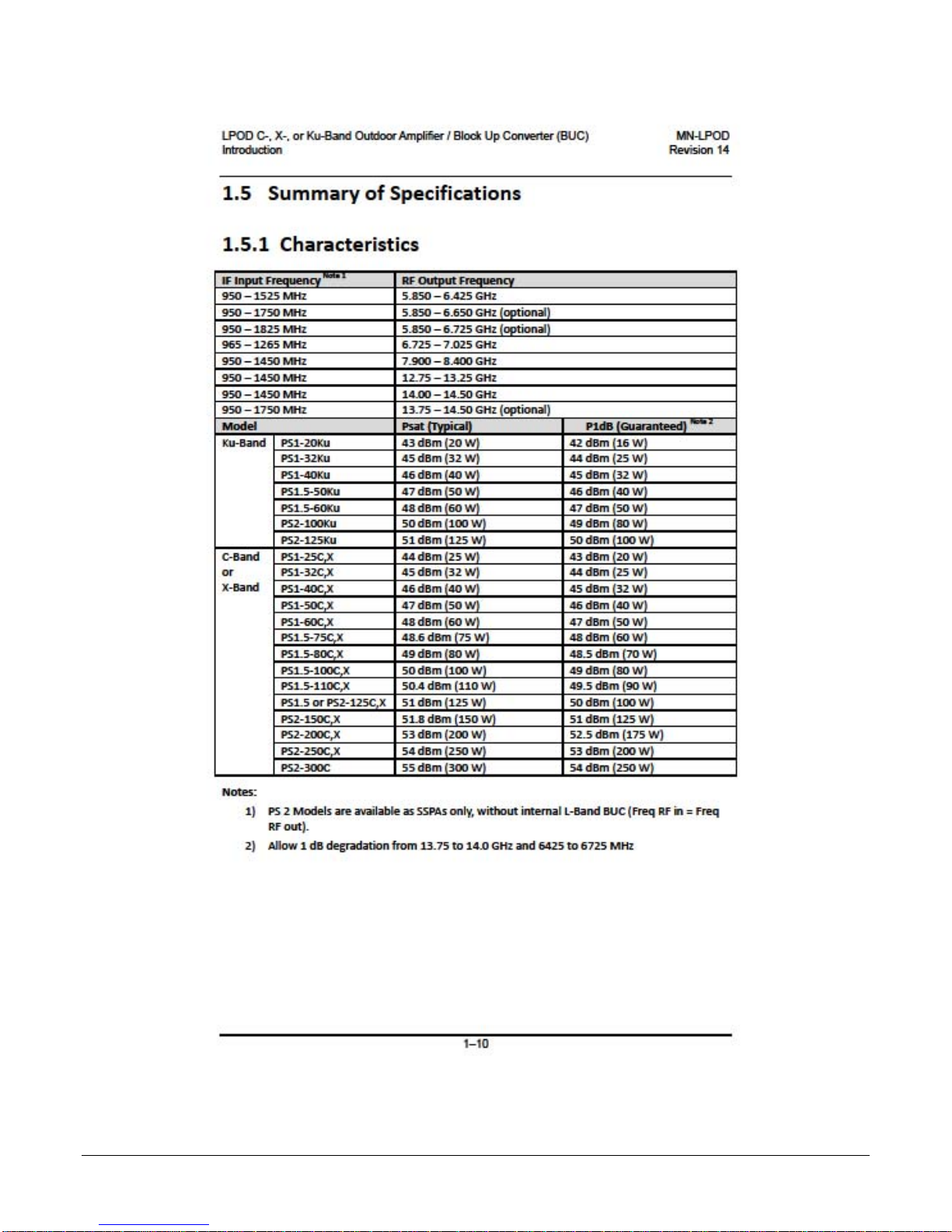
1.5 Summary of Specifications .............................................................. 1–10
1.5.1 Characteristics .................................................................................... 1–10
1.5.2 Optional Internal Reference ............................................................... 1–12
1.5.3 Optional LNB Bias / Reference ........................................................... 1–12
1.5.4 Environmental .................................................................................... 1–12
1.5.5 Physical ............................................................................................... 1–13
1.6 Dimensional Envelopes ................................................................... 1–14
1.6.1 LPOD PS 1 Dimensional Envelopes..................................................... 1–15
1.6.2 LPOD PS 1.5 Dimensional Envelopes.................................................. 1–21
1.6.3 LPOD PS 2 Dimensional Envelopes..................................................... 1–25
CHAPTER 2. SYSTEM CONNECTORS, INSTALLATION, AND
STARTUP ....................................................................................... 2–1
2.1 Overview .......................................................................................... 2–1
2.2 Water Tight Sealing ........................................................................... 2–2
2.2.1 Customer Cable Assemblies ................................................................. 2–2
2.3 LPOD Interface Connectors ................................................................ 2–3
2.3.1 Connector ‘J1 | LBAND IN’ or ‘J1 | Tx IN’ ............................................. 2–4
2.3.2 Connector ‘J2 | RF OUT’ ....................................................................... 2–4
iv
Page 9

LPOD C-, X-, or Ku-Band Outdoor Amplifier / Block Up Converter (BUC) MN-LPOD / CD-LPOD
Table of Contents Revision 14
2.3.3 Connector ‘J3 | POWER IN’ AC Power Mains ....................................... 2–5
2.3.3.1 LPOD PS 1, PS 1.5 ‘J3 | POWER IN’ AC Power Main .................. 2–6
2.3.3.2 LPOD PS 2 ‘J3 | POWER IN’ AC Power Main .............................. 2–6
2.3.4 Connector ‘J3 | POWER IN’ DC Power Mains ....................................... 2–7
2.3.4.1 LPOD PS 1 ‘J3 | POWER IN’ DC Power Main .............................. 2–7
2.3.4.2 LPOD PS 1.5 ‘J3 | POWER IN’ DC Power Main ........................... 2–8
2.3.4.3 LPOD PS 2 ‘J3 | POWER IN’ DC Power Main .............................. 2–8
2.3.4.4 LPOD PS 2 ‘J3 | POWER IN’ 48VDC Power Main Option ........... 2–9
2.3.5 Connector ‘J6 | COM1’ (Remote Communications and Discrete Control
Port) ............................................................................................................ 2–10
2.3.5.1 About Circular Connectors ...................................................... 2–11
2.3.6 Connector ‘J9 | OUTPUT SAMPLE’ (PS 2 ONLY) ................................. 2–12
2.3.7 Connectors ‘J10 | MODEM Rx’ and ‘J11 | LNB’ (Optional Interfaces)
............................................................................................................ 2–12
2.3.8 Ground Connector ............................................................................. 2–13
2.4 LPOD Standalone (Single-Thread) Installations ................................. 2–14
2.4.1 Manpower Requirements .................................................................. 2–14
2.4.2 Typical Required Installation Tools ..................................................... 2–14
2.4.3 Pole-Mounted Installations ................................................................ 2–15
2.4.3.1 PL/12319-1 Universal Pole Mounting Kit................................. 2–16
2.4.3.2 KT-0000095 Single Unit Mounting Kit (LPOD PS 1, PS 1.5) ..... 2–19
2.4.3.3 KT-0000125 Single Unit Mounting Kit (LPOD PS 2) ................. 2–20
2.4.4 Spar-Mounted Installations (LPOD PS 1, PS 1.5) ................................ 2–21
2.4.5 Shelf-Mounted Installations (LPOD PS 2) ........................................... 2–23
2.5 Set the LPOD Power ON................................................................... 2–24
CHAPTER 3. FIRMWARE UPDATE .................................................... 3–1
3.1 Firmware Update Overview ............................................................... 3–1
3.1.1 LPOD Firmware Update Procedure Summary ...................................... 3–1
3.1.2 About Firmware Numbers, File Versions, and Formats ....................... 3–2
3.2 Prepare for the Firmware Download .................................................. 3–2
3.2.1 Required User-supplied Items .............................................................. 3–2
3.2.1.1 LPOD Connections ..................................................................... 3–3
3.2.2 Configure the Terminal Emulator Program .......................................... 3–4
3.2.3 Get the LPOD Management IP Address and Firmware Information ... 3–5
v
Page 10

LPOD C-, X-, or Ku-Band Outdoor Amplifier / Block Up Converter (BUC) MN-LPOD / CD-LPOD
Table of Contents Revision 14
3.2.3.1 Use the HTTP Interface to Find the Firmware Information ...... 3–5
3.2.3.2 Use the Serial Interface to Find the Firmware Information ...... 3–6
3.2.4 Make a Temporary Folder (Subdirectory) on the User PC ................... 3–7
3.2.4.1 Use Windows Desktop to Make a Folder .................................. 3–7
3.2.4.2 Use Windows Explorer to Make a Folder .................................. 3–8
3.2.4.3 Use the Run and Browse Windows to Make a Folder ............... 3–8
3.2.4.4 Use Windows Command-line or Command Prompt to Make a
Folder ................................................................................................... 3–9
3.3 Download and Extract the Firmware Update Files ............................ 3–10
3.3.1.1 Use Windows Desktop to View Folder Contents .................... 3–12
3.3.1.2 Use Windows Command-line to View Folder Contents .......... 3–12
3.4 Upload the Firmware Files and Update the LPOD Unit ..................... 3–12
3.4.1 Important Considerations .................................................................. 3–12
3.4.2 Steps to FTP Upload the Firmware Files ............................................ 3–13
3.4.3 OPTIONAL: Steps to “CReflash” Upload the Firmware Files .............. 3–14
3.4.4 Steps to Update the LPOD Unit .......................................................... 3–15
CHAPTER 4. ETHERNET INTERFACE OPERATION ........................ 4–1
4.1 Overview .......................................................................................... 4–1
4.1.1 Prerequisites ........................................................................................ 4–1
4.2 SNMP Interface ................................................................................. 4–2
4.2.1 Management Information Base (MIB) Files ......................................... 4–2
4.2.1.1 ComtechEFData Root MIB file ................................................... 4–2
4.2.1.2 LPOD MIB file ............................................................................ 4–3
4.2.1.3 LPOD Traps MIB file ................................................................... 4–3
4.2.2 SNMP Community Strings .................................................................... 4–3
4.2.3 SNMP Traps .......................................................................................... 4–3
4.3 Telnet Interface ................................................................................. 4–6
4.3.1 Using HyperTerminal for Telnet Remote Control Operation ................ 4–6
4.3.1.1 Configure HyperTerminal for Telnet Remote Control Operation4–7
4.4 HTTP (Web Server) Interface ............................................................. 4–8
4.4.1 Enable the HTTP Interface ................................................................... 4–8
4.4.2 HTTP Interface User Login .................................................................. 4–10
4.4.3 HTTP Interface Features ..................................................................... 4–11
vi
Page 11

LPOD C-, X-, or Ku-Band Outdoor Amplifier / Block Up Converter (BUC) MN-LPOD / CD-LPOD
Table of Contents Revision 14
4.4.3.1 Menu Tree ............................................................................... 4–11
4.4.3.2 Page Navigation ....................................................................... 4–11
4.4.3.3 Page Sections ........................................................................... 4–11
4.4.3.4 Action Buttons ......................................................................... 4–12
4.4.3.5 Drop-down Lists ....................................................................... 4–12
4.4.3.6 Text or Data Entry .................................................................... 4–12
4.5 HTTP Interface Page Examples and Descriptions .............................. 4–13
4.5.1 Home Pages ........................................................................................ 4–13
4.5.1.1 Home | Home .......................................................................... 4–13
4.5.1.2 Home | Contact ....................................................................... 4–14
4.5.1.3 Home | Support ...................................................................... 4–15
4.5.2 Admin (Administration) Pages ........................................................... 4–16
4.5.2.1 Admin | Access ........................................................................ 4–16
4.5.2.2 Admin | SNMP ......................................................................... 4–18
4.5.3 Config Pages ....................................................................................... 4–19
4.5.3.1 Config | Amplifier .................................................................... 4–19
4.5.3.2 Config | LNB ............................................................................ 4–21
4.5.3.3 Config | Utility ......................................................................... 4–23
4.5.3.4 Config | Redundancy ............................................................... 4–25
4.5.4 Status Pages ....................................................................................... 4–26
4.5.4.1 Status | Summary .................................................................... 4–26
4.5.4.2 Status | Status .......................................................................... 4–27
4.5.4.4 Status | Events ......................................................................... 4–29
4.5.4.5 Status | Statistics ..................................................................... 4–31
4.5.4.6 Status | Trending Graphs ......................................................... 4–33
CHAPTER 5. SERIAL INTERFACE OPERATION ............................... 5–1
5.1 Overview .......................................................................................... 5–1
5.2 Key Operational Parameters / Common Commands and Queries ....... 5–1
5.2.1 RF Input Level ....................................................................................... 5–1
5.2.2 Attenuator Control ............................................................................... 5–2
5.2.3 Mute Control ........................................................................................ 5–2
5.2.4 Faults .................................................................................................... 5–2
5.2.5 Power Detector .................................................................................... 5–3
5.2.6 Common Queries ................................................................................. 5–3
5.2.7 End-of-Life Commands/Queries ........................................................... 5–4
vii
Page 12

LPOD C-, X-, or Ku-Band Outdoor Amplifier / Block Up Converter (BUC) MN-LPOD / CD-LPOD
Table of Contents Revision 14
5.3 Remote Control Protocol and Structure ............................................. 5–4
5.3.1 EIA-232 ................................................................................................. 5–4
5.3.2 EIA-485 ................................................................................................. 5–5
5.3.3 Basic Serial Protocol ............................................................................. 5–5
5.3.4 Basic Protocol ....................................................................................... 5–6
5.3.5 Packet Structure ................................................................................... 5–6
5.3.5.1 Start of Packet ........................................................................... 5–7
5.3.5.2 Target Address ........................................................................... 5–7
5.3.5.3 Address Delimiter ...................................................................... 5–7
5.3.5.4 Instruction Code ........................................................................ 5–7
5.3.5.5 Instruction Code Qualifier ......................................................... 5–8
5.3.5.5.1 Controller-to-Target Rules ...................................................... 5–8
5.3.5.5.2 Target-to-Controller Rules ...................................................... 5–8
5.3.5.6 Optional Message Arguments ................................................... 5–9
5.3.5.7 End of Packet ............................................................................. 5–9
5.4 Remote Commands and Queries...................................................... 5–10
APPENDIX A . 1:1 REDUNDANCY ..................................................... A–1
A.1 LPOD Redundancy Operation Overview ............................................. A–1
A.2 1:1 Redundancy Mode ....................................................................... A–2
A.2.1 Ethernet-based Monitor and Control .................................................. A–2
A.2.1.1 1:1 Redundancy System Setup (Using a Single Ethernet Interface)
................................................................................................... A–3
A.2.2 Serial-based Monitor and Control ........................................................ A–4
A.2.2.1 Applicable Serial-Based Redundancy Commands and Queries
................................................................................................... A–8
A.2.3 Troubleshooting Connectivity Issues ................................................... A–8
A.3 1:1 Redundancy System Cabling and Installation .............................. A–10
A.3.1 Water Tight Sealing ............................................................................ A–10
A.4 1:1 Redundancy System Assembly Kit Examples............................... A–12
A.4.1 Common Kit Examples ....................................................................... A–13
A.4.2 LPOD PS 1 1:1 Redundancy Kit Examples .......................................... A–28
A.4.3 LPOD PS 1.5 1:1 Redundancy Kit Examples ....................................... A–44
A.4.4 LPOD PS 2 1:1 Redundancy Kit Examples .......................................... A–52
viii
Page 13

LPOD C-, X-, or Ku-Band Outdoor Amplifier / Block Up Converter (BUC) MN-LPOD / CD-LPOD
Table of Contents Revision 14
APPENDIX B. CABLE DRAWINGS .................................................... B-1
B.1 Overview ........................................................................................... B-1
B.2 Control and Data Cables ..................................................................... B-2
B.2.1 Serial Interface Cable ............................................................................ B-3
B.2.2 Ethernet Interface Cable ....................................................................... B-4
B.2.3 19-Pin COMMS Cable (100’) ................................................................. B-5
B.2.4 19-Pin COMMS Cable (250’) ................................................................. B-6
B.2.5 Redundant Loop Cable – Rx / Tx ........................................................... B-7
B.2.6 Redundant Loop Cable – Tx Only .......................................................... B-8
B.3 RF Cables ......................................................................................... B-10
B.3.1 RF Cable (Type ‘N’) .............................................................................. B-11
APPENDIX C. MAINTENANCE .......................................................... C–1
C.1 Overview .......................................................................................... C–1
C.2 Clean the LPOD PS 1 Heat Sinks ......................................................... C–2
C.3 Clean the LPOD PS 1.5 Heat Sinks ...................................................... C–6
C.4 Clean the LPOD PS 2 Heat Sinks ....................................................... C–10
C.5 Water Tight Sealing ......................................................................... C–14
TABLES
Table 2-1. ‘J2 | RF OUT’ Interface Type ............................................................... 2–4
Table 2-2. LPOD PS 1/PS 1.5 ‘J3 | POWER IN’ Pin Assignments .......................... 2–6
Table 2-3. LPOD PS 2 ‘J3 | POWER IN’ Pin Assignments ..................................... 2–6
Table 2-4. LPOD PS 1 ‘J3 | POWER IN’ Pin Assignments ..................................... 2–7
Table 2-5. LPOD PS 1.5 ‘J3 | POWER IN’ Pin Assignments .................................. 2–8
Table 2-6. LPOD PS 2 ‘J3 | POWER IN’ Pin Assignments ..................................... 2–8
Table 2-7. LPOD PS 2 ‘J3 | POWER IN’ 48VDC Pin Assignments.......................... 2–9
Table 2-8. LPOD ‘J6 | COM1’ Pin Assignments .................................................. 2–10
Table A-1. OFM Online-to-Offline Operational Settings Conveyance ................. A–7
Table A-2. Parts List for KT-0000098 LPOD C-Band Rx Switch Kit ..................... A–16
Table A-3. Parts List for PL/7596-1 LPOD Ku-Band Rx Switch Kit ...................... A–20
ix
Page 14

LPOD C-, X-, or Ku-Band Outdoor Amplifier / Block Up Converter (BUC) MN-LPOD / CD-LPOD
Table of Contents Revision 14
Table A-4. Parts List for KT-0000191 Ku-Band Rx Switch Kit, OMT-Mounted, Metric
................................................................................................................... A–24
Table A-5. Parts List for KT-0000104 LPOD PS 1 1:1 Redundancy Kit ................ A–28
Table A-6. Parts List for KT-0000090 LPOD PS 1 C-Band Coax Output 1:1
Redundancy Kit .......................................................................................... A–32
Table A-7. Parts List for KT-0000089 LPOD PS 1 Ku-Band 1:1 Redundancy Kit . A–36
Table A-8. Parts List for KT-0000170 LPOD PS 1 X-Band 1:1 Redundancy Kit ... A–40
Table A-9. Parts List for KT-0020526 LPOD PS 1.5 C-Band DC Option 1:1
Redundancy Kit .......................................................................................... A–44
Table A-10. Parts List for KT-0000060 LPOD PS 1.5 Ku-Band 1:1 Redundancy Kit ....
................................................................................................................... A–48
Table A-11. Parts List for KT-0000091 LPOD PS 2 C-Band 1:1 Redundancy Kit
................................................................................................................... A–54
Table A-12. Parts List for KT-0000254 LPOD PS 2 Ku-Band 1:1 Redundancy Kit .......
................................................................................................................... A–58
FIGURES
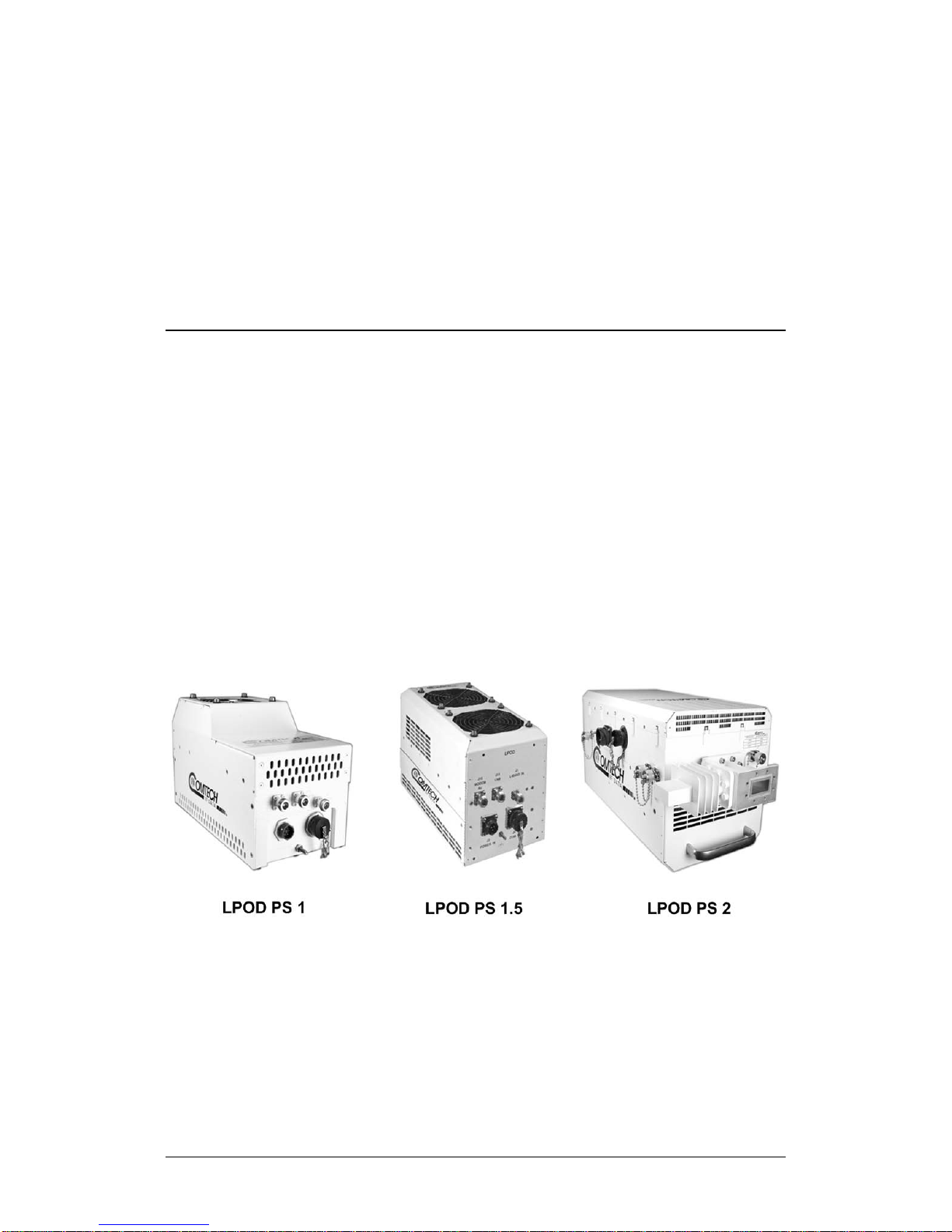
Figure 1-1. Comtech EF Data LPOD Outdoor Amplifiers / BUCs ......................... 1–1
Figure 1-2. LPOD PS 1/1.5 Block Diagram ............................................................ 1–5
Figure 1-3. LPOD PS 2 Block Diagram ................................................................. 1–6
Figure 1-4. LPOD PS 1 C-Band Dimensional Envelope (Coax Output) .............. 1–15
Figure 1-5. LPOD PS 1 C-Band Dimensional Envelope (Coax Output) – Reduced
Height Unit ................................................................................................. 1–16
Figure 1-6. LPOD PS 1 C-Band Dimensional Envelope ...................................... 1–17
Figure 1-7. LPOD PS 1 X-Band Dimensional Envelope ...................................... 1–18
Figure 1-8. LPOD PS 1 Ku-Band Dimensional Envelope .................................... 1–19
Figure 1-9. LPOD PS 1 Ku-Band Dimensional Envelope – Reduced Height Unit
................................................................................................................... 1–20
Figure 1-10. LPOD PS 1.5 C-Band Dimensional Envelope (DC Option) ............. 1–21
Figure 1-11. LPOD PS 1.5 C-Band Dimensional Envelope (AC Option) ............. 1–22
Figure 1-12. LPOD PS 1.5 X-Band Dimensional Envelope ................................. 1–23
Figure 1-13. LPOD PS 1.5 Ku-Band Dimensional Envelope ............................... 1–24
Figure 1-14. LPOD PS 2 C-Band Dimensional Envelope .................................... 1–25
Figure 1-15. LPOD PS 2 X-Band Dimensional Envelope .................................... 1–26
Figure 1-16. LPOD PS 2 Ku-Band Dimensional Envelope .................................. 1–27
Figure 2-1. LPOD PS 1 Connectors ...................................................................... 2–3
Figure 2-2. LPOD PS 1.5 Connectors ................................................................... 2–3
x
Page 15

LPOD C-, X-, or Ku-Band Outdoor Amplifier / Block Up Converter (BUC) MN-LPOD / CD-LPOD
Table of Contents Revision 14
Figure 2-3. LPOD PS 2 Connectors ...................................................................... 2–3
Figure 2-4. Circular Connector Example ........................................................... 2–11
Figure 2-5. LPOD ‘J10 | Modem Rx’ and ‘J11 | LNB’ Connectors ..................... 2–12
Figure 2-6. LPOD Ground Connector Locations ................................................ 2–13
Figure 2-7. PL/12319-1 Universal Pole Mounting Kit ........................................ 2–16
Figure 2-8. Universal Pole Mounting Kit – Final Assembly ............................... 2–18
Figure 2-9. KT-0000095 LPOD PS 1, PS 1.5 Single Unit Mounting Kit ............... 2–19
Figure 2-10. KT-0000125 LPOD PS 2 Single Unit Mounting Kit ......................... 2–20
Figure 2-11. SSPA Spar Mount Installation Example ......................................... 2–21
Figure 2-12. LPOD PS 1, PS 1.5 Spar Mount Installation Kits ............................ 2–22
Figure 2-13. KT-0020524 LPOD PS 2 Single Unit Shelf Style Mounting Kit ....... 2–23
Figure 3-1. Standalone or Redundant Serial Connection ................................... 3–3
Figure 3-2. Standalone or Redundant Ethernet Connection .............................. 3–4
Figure 4-1. Telnet Interface Example – Windows Command-line ...................... 4–6
Figure 4-2. Telnet Interface Example – HyperTerminal ....................................... 4–7
Figure 4-3. Configure HyperTerminal .................................................................. 4–7
Figure 4-4. Open Windows Command-line ........................................................ 4–8
Figure 4-5. Telnet Login and Remote Command Execution ................................ 4–9
Figure 4-6. LPOD HTTP Interface “Splash” Page Example ................................. 4–10
Figure 4-7. LPOD HTTP Interface Menu Tree .................................................... 4–11
Figure 4-8. LPOD ‘Home | Home’ Page (PS .5 Unit Example Shown) ............... 4–13
Figure 4-9. ‘Home | Contact’ Page ................................................................... 4–14
Figure 4-10. ‘Home | Support’ Page ................................................................. 4–15
Figure 4-11. ‘Admin | Access’ Page ................................................................... 4–16
Figure 4-12. ‘Admin | SNMP’ Page .................................................................... 4–18
Figure 4-13. ‘Config | Amplifier’ Page .............................................................. 4–19
Figure 4-14. ‘Config | LNB’ Page ....................................................................... 4–21
Figure 4-15. ‘Config | Utility’ Page.................................................................... 4–23
Figure 4-16. ‘Config | Redundancy’ Page ......................................................... 4–25
Figure 4-17. ‘Status | Summary’ Page .............................................................. 4–26
Figure 4-18. ‘Status | Status’ page .................................................................... 4–27
Figure 4-19. ‘Status | FETs’ Page ....................................................................... 4–28
Figure 4-20. ‘Status | Events’ Page ................................................................... 4–29
Figure 4-21. ‘Status | Statistics’ Page ................................................................ 4–31
Figure 4-22. ‘Status | Trending Graphs’ Page ................................................... 4–33
Figure A-1. Ethernet-based M&C using CEFD Kit KT-0000203 ............................ A–2
Figure A-2. Serial-based M&C using CEFD Kit KT-0020518 ................................. A–4
Figure A-3. Typical LPOD 1:1 Redundancy System Cabling Schematic ............. A–11
Figure A-4. 1:1 Free Standing Unitstrut Kit (CEFD Kit KT-0020827) .................. A–13
xi
Page 16

LPOD C-, X-, or Ku-Band Outdoor Amplifier / Block Up Converter (BUC) MN-LPOD / CD-LPOD
Table of Contents Revision 14
Figure A-5. KT-0000116 LPOD Rx Splitter / Cable Kit Example – Exploded and
Assembled Isometric Views ....................................................................... A–14
Figure A-6. KT-0000098 LPOD C-Band Rx Switch Kit Example – Exploded Isometric
View ........................................................................................................... A–17
Figure A-7. KT-0000098 LPOD C-Band Rx Switch Kit Example – Assembled
Isometric View ........................................................................................... A–18
Figure A-8. PL/7596-1 LPOD Ku-Band Rx Switch Kit Example – Exploded Isometric
View ........................................................................................................... A–21
Figure A-9. PL/7596-1 LPOD Ku-Band Rx Switch Kit – Assembled Isometric View
................................................................................................................... A–22
Figure A-10. KT-0000191 Ku-Band Rx Switch Kit Example, OMT-Mounted, Metric
– Exploded Isometric View ........................................................................ A–25
Figure A-11. KT-0000191 Ku-Band Rx Switch Kit Example, OMT-Mounted, Metric
– Assembled Isometric View ..................................................................... A–26
Figure A-12. KT-0000104 LPOD PS 1 C-Band 1:1 Redundancy Kit Example –
Exploded Isometric View ........................................................................... A–29
Figure A-13. KT-0000104 LPOD PS 1 C-Band 1:1 Redundancy Kit Example –
Assembled Isometric View ........................................................................ A–30
Figure A-14. KT-0000090 LPOD PS 1 C-Band Coax Output 1:1 Redundancy Kit
Example – Exploded Isometric View ......................................................... A–33
Figure A-15. KT-0000090 LPOD PS 1 C-Band Coax Output 1:1 Redundancy Kit
Example – Assembled Isometric View ....................................................... A–34
Figure A-16. KT-0000089 LPOD PS 1 Ku-Band 1:1 Redundancy Kit Example –
Exploded Isometric View ........................................................................... A–37
Figure A-17. KT-0000089 LPOD PS 1 Ku-Band 1:1 Redundancy Kit Example –
Assembled Isometric View ........................................................................ A–38
Figure A-18. KT-0000170 LPOD PS 1 X-Band 1:1 Redundancy Kit Example –
Exploded Isometric View ........................................................................... A–41
Figure A-19. KT-0000170 LPOD PS 1 X-Band 1:1 Redundancy Kit Example –
Assembled Isometric View ........................................................................ A–42
Figure A-20. KT-0020526 LPOD PS 1.5 C-Band DC Option 1:1 Redundancy Kit
Example – Exploded Isometric Views, Steps 1 & 2 .................................... A–45
Figure A-21. KT-0020526 LPOD PS 1.5 C-Band DC Option 1:1 Redundancy Kit
Example – Exploded Isometric View, Step 3 .............................................. A–46
Figure A-22. KT-0020526 LPOD PS 1.5 C-Band DC Option 1:1 Redundancy Kit
Example – Assembled Isometric View ....................................................... A–47
Figure A-23. KT-0000060 LPOD PS 1.5 Ku-Band 1:1 Redundancy Kit Example –
Exploded Isometric View ........................................................................... A–49
xii
Page 17

LPOD C-, X-, or Ku-Band Outdoor Amplifier / Block Up Converter (BUC) MN-LPOD / CD-LPOD
Table of Contents Revision 14
Figure A-24. KT-0000060 LPOD PS 1.5 Ku-Band 1:1 Redundancy Kit Example –
Assembled Isometric View ........................................................................ A–50
Figure A-25. PS 2 C-Band 1:1 Redundancy Free Standing Kit Example Using KT-
0020827 – Assembled Isometric View ...................................................... A–52
Figure A-26. PS 2 C-Band 1:1 Redundancy Free Standing Kit Example Using KT-
0020827 – Assembled Views ..................................................................... A–53
Figure A-27. KT-0000091 LPOD PS 2 C-Band 1:1 Redundancy Kit Example –
Exploded Isometric View ........................................................................... A–55
Figure A-28. KT-0000091 LPOD PS 2 C-Band 1:1 Redundancy Kit Example –
Assembled Isometric View ........................................................................ A–56
Figure A-29. KT-0000254 LPOD PS 2 Ku-Band 1:1 Redundancy Kit Example –
Exploded Isometric View ........................................................................... A–59
Figure A-30. KT-0000254 LPOD PS 2 Ku-Band 1:1 Redundancy Kit Example –
Assembled Isometric View ........................................................................ A–60
Figure B-1. Serial Interface Cable (CEFD P/N CA-0020526, part of KT-0020518)
...................................................................................................................... B-3
Figure B-2. Ethernet Interface Cable (CEFD P/N CA-0000352, part of KT-0000203)
...................................................................................................................... B-4
Figure B-3. COMMS Cable , 100’ (CEFD P/N CA-0000318) .................................. B-5
Figure B-4. COMMS Cable, 250’ (CEFD P/N CA-0000543) ................................... B-6
Figure B-5. Redundant Loop Cable – Rx / Tx (CEFD P/N CA-0020657) ................. B-7
Figure B-6. Redundant Loop Cable –Tx Only (CEFD P/N CA-0020655) ................ B-8
Figure B-7. 1/4" Heliax Coaxial Cable (CEFD P/N CA/3722-X) ............................. B-11
Figure C-1. Comtech EF Data LPOD Outdoor Amplifiers / BUCs ......................... C–1
Figure C-2. LPOD HTTP Interface ‘Status |Trending Graphs’ Page – Temperature
Graph Example ............................................................................................. C–2
Figure C-3. LPOD PS 1 Shroud Screw Locations .................................................. C–3
Figure C-4. Remove the Fan Shroud ................................................................... C–4
Figure C-5. Disconnect the Fan Power Supply .................................................... C–4
Figure C-6. LPOD PS 1 Heat Sink Locations ......................................................... C–5
Figure C-7. Reconnect the Fan Power Supply ..................................................... C–5
Figure C-8. LPOD PS 1.5 Shroud Screw Locations ............................................... C–7
Figure C-9. Remove the Fan Shroud ................................................................... C–8
Figure C-10. Disconnect the Fan 1 / Fan 2 Power Supplies ................................. C–8
Figure C-11. LPOD PS 1.5 Heat Sink Location ...................................................... C–9
Figure C-12. Reconnect the Fan 1 / Fan 2 Power Supplies ................................. C–9
Figure C-13. LPOD PS 2 Shroud Screw Locations .............................................. C–11
Figure C-14. Remove the Fan Shroud ............................................................... C–11
Figure C-15. Disconnect the Fan 1 / Fan 2 Power Supplies ............................... C–12
xiii
Page 18

LPOD C-, X-, or Ku-Band Outdoor Amplifier / Block Up Converter (BUC) MN-LPOD / CD-LPOD
Table of Contents Revision 14
Figure C-16. LPOD PS 2 Heat Sink Locations ..................................................... C–12
Figure C-17. Reconnect the Fan 1 / Fan 2 Power Supplies ............................... C–13
xiv
Page 19

PREFACE
About this Manual
This manual provides installation and operation information for the Comtech EF
Data LPOD family of Outdoor Amplifiers / Block Up Converter (BUCs). This
document is intended for the persons responsible for the operation and
maintenance of the LPOD PS 1, PS 1.5, or PS 2.
Related Documents
• Comtech EF Data CLC-10 Handheld Terminal M&C Accessory for LPOD or
SPOD PS 1, PS 1.5, PS 2 User’s Guide (CEFD P/N MN-CLC10)
• Comtech EF Data LPODnet M&C Netbook Accessory for LPOD or SPOD
PS 1, PS 1.5, PS 2 Operation Manual (CEFD P/N MN-LPODNET)
• Comtech EF Data RF Control – Transceiver/Amplifier M&C Utility User
Guide (CEFD P/N MN-CRFC)
Disclaimer
Comtech EF Data has reviewed this manual thoroughly in order to provide an
easy-to-use guide to this equipment. All statements, technical information, and
recommendations in this manual and in any guides or related documents are
believed reliable, but the accuracy and completeness thereof are not guaranteed
or warranted, and they are not intended to be, nor should they be understood to
be, representations or warranties concerning the products described. Further,
Comtech EF Data reserves the right to make changes in the specifications of the
products described in this manual at any time without notice and without
obligation to notify any person of such changes.
xv
Page 20

LPOD C-, X-, or Ku-Band Outdoor Amplifier / Block Up Converter (BUC) MN-LPOD
equipment.
A REFERENCE directs you to important operational information or
Preface Revision 14
If there are any questions regarding this equipment or the information in this
manual, please contact Comtech EF Data Product Support.
Conventions and References
Patents and Trademarks
See all of Comtech EF Data's Patents and Patents Pending at
http://patents.comtechefdata.com.
Comtech EF Data acknowledges that all trademarks are the property of the
trademark owners.
Warnings, Cautions, Notes, and References
A WARNING indicates a potentially hazardous situation that, if not
avoided, could result in death or serious injury.
A CAUTION indicates a hazardous situation that, if not avoided, may
result in minor or moderate injury. CAUTION may also be used to
indicate other unsafe practices or risks of property damage.
A NOTE: gives you important information about a task or the
details furnished elsewhere, either in the manual or in adjunct
Comtech EF Data publications.
Examples of Multi-Hazard Notices
xvi
Page 21

LPOD C-, X-, or Ku-Band Outdoor Amplifier / Block Up Converter (BUC) MN-LPOD
POWER SUPPLY INPUT.
Preface Revision 14
Recommended Standard Designations
Electronic Industries Association (EIA) designations supersede Recommended
Standard (RS) designations. Reference to the old RS designations may appear
where it might concern actual text (e.g., RS-232) displayed on the product panels
and on screens or pages in the Serial Remote or HTTP (Web Server) Interfaces.
All other references in the manual refer to EIA designations.
CAUTION
It is important that you review and understand the Safety and
Compliance information that follows.
Safety and Compliance
Electrical Safety and Compliance
CAUTION
NEUTRAL FUSING – DOUBLE POLE/NEUTRAL FUSING IS USED ON THE PRIME
This equipment has been designed to minimize exposure of personnel to
hazards. For further information, contact Comtech EF Data Product Support. The
operators and technicians must:
• Know how to work around, with, and on high voltage equipment.
• Exercise every precaution to ensure personnel safety.
• Exercise extreme care when working near high voltages.
• Be familiar with the warnings presented in this manual.
Installation Guidelines Regarding Power Line Quality
Comtech EF Data has become familiar with the varying quality of the AC power
grid around the world. Observing the following installation guidelines should
help ensure a reliable installation.
• Surge suppression – High voltage surges can cause failure of the power
supply. These surges are typically caused by circuit switching on the main
AC power grid, erratic generator operation, and also by lightning strikes.
xvii
Page 22

LPOD C-, X-, or Ku-Band Outdoor Amplifier / Block Up Converter (BUC) MN-LPOD
Preface Revision 14
While the LPOD does have built in surge suppression, if the unit is to be
installed in a location with questionable power grid quality, Comtech EF
Data recommends installation of additional power conditioning/surge
suppression at the power junction box.
• Grounding – The LPOD provides a grounding terminal. This is provided to
allow you to ground the LPOD to the antenna’s grounding network. All
components installed at the antenna should be grounded to a common
grounding point at the antenna.
• Electrical welding – If welding needs to take place at the antenna,
disconnect all cables from the LPOD except for the ground wire. Cap all
RF connections with terminations. This will prevent damage to the
input/output circuitry of the LPOD.
• Lightning – Lightning strikes on or around the antenna will generate
extremely high voltages on all cables connected to the LPOD. Depending
on the severity of the strike, the LPOD’s internal surge protection
combined with the recommended external suppression may protect the
LPOD’s power supply. However, if the installation will be in an area with a
high probability of lightning strikes, Comtech EF Data recommends the
installation of surge suppression on the RF and IF cables. One source of
these suppressors is PolyPhaser (www.polyphaser.com).
Product Support
For all product support, please call:
+1.240.243.1880
+1.866.472.3963 (toll free USA)
Comtech EF Data Headquarters
http://www.comtechefdata.com
Comtech EF Data Corp.
2114 West 7th Street
Tempe, Arizona USA 85281
+1.480.333.2200
xviii
Page 23

LPOD C-, X-, or Ku-Band Outdoor Amplifier / Block Up Converter (BUC) MN-LPOD
Preface Revision 14
Warranty Policy
Comtech EF Data products are warranted against defects in material and
workmanship for a specific period from the date of shipment, and this period
varies by product. In most cases, the warranty period is two years. During the
warranty period, Comtech EF Data will, at its option, repair or replace products
that prove to be defective. Repairs are warranted for the remainder of the
original warranty or a 90 day extended warranty, whichever is longer. Contact
Comtech EF Data for the warranty period specific to the product purchased.
For equipment under warranty, the owner is responsible for freight to Comtech
EF Data and all related customs, taxes, tariffs, insurance, etc. Comtech EF Data is
responsible for the freight charges only for return of the equipment from the
factory to the owner. Comtech EF Data will return the equipment by the same
method (i.e., Air, Express, Surface) as the equipment was sent to Comtech EF
Data.
All equipment returned for warranty repair must have a valid RMA number
issued prior to return and be marked clearly on the return packaging. Comtech
EF Data strongly recommends all equipment be returned in its original
packaging.
Comtech EF Data Corporation’s obligations under this warranty are limited to
repair or replacement of failed parts, and the return shipment to the buyer of
the repaired or replaced parts.
Limitations of Warranty
The warranty does not apply to any part of a product that has been installed,
altered, repaired, or misused in any way that, in the opinion of Comtech EF Data
Corporation, would affect the reliability or detracts from the performance of any
part of the product, or is damaged as the result of use in a way or with
equipment that had not been previously approved by Comtech EF Data
Corporation.
The warranty does not apply to any product or parts thereof where the serial
number or the serial number of any of its parts has been altered, defaced, or
removed.
xix
Page 24

LPOD C-, X-, or Ku-Band Outdoor Amplifier / Block Up Converter (BUC) MN-LPOD
Preface Revision 14
The warranty does not cover damage or loss incurred in transportation of the
product. The warranty does not cover replacement or repair necessitated by loss
or damage from any cause beyond the control of Comtech EF Data Corporation,
such as lightning or other natural and weather related events or wartime
environments.
The warranty does not cover any labor involved in the removal and or
reinstallation of warranted equipment or parts on site, or any labor required to
diagnose the necessity for repair or replacement.
The warranty excludes any responsibility by Comtech EF Data Corporation for
incidental or consequential damages arising from the use of the equipment or
products, or for any inability to use them either separate from or in combination
with any other equipment or products.
A fixed charge established for each product will be imposed for all equipment
returned for warranty repair where Comtech EF Data Corporation cannot
identify the cause of the reported failure.
Exclusive Remedies
Comtech EF Data Corporation’s warranty, as stated is in lieu of all other
warranties, expressed, implied, or statutory, including those of merchantability
and fitness for a particular purpose. The buyer shall pass on to any purchaser,
lessee, or other user of Comtech EF Data Corporation’s products, the
aforementioned warranty, and shall indemnify and hold harmless Comtech EF
Data Corporation from any claims or liability of such purchaser, lessee, or user
based upon allegations that the buyer, its agents, or employees have made
additional warranties or representations as to product preference or use.
The remedies provided herein are the buyer’s sole and exclusive remedies.
Comtech EF Data shall not be liable for any direct, indirect, special, incidental, or
consequential damages, whether based on contract, tort, or any other legal
theory.
xx
Page 25
Chapter 1. INTRODUCTION
1.1 Overview
Comtech EF Data’s LPOD family of Outdoor Amplifiers / Block Up Converters
(BUCs) – referred to collectively throughout this manual as the LPOD – deliver
their rated power, guaranteed, to the transmit waveguide flange at the 1 dB
compression point. The LPOD provides a cost effective, more reliable
replacement for Traveling Wave Tube (TWT) amplifiers in satellite
communications.
Comtech EF Data’s extensive experience in the design of outdoor RF transceivers
led to the LPOD family’s efficient thermal and mechanical package. Recognizing
the evolution of L-Band IF systems, the LPOD is designed to eliminate the
traditional requirement for the modem to supply a DC power source and a 10
MHz reference to the BUCs and LNBs.
Figure 1-1. Comtech EF Data LPOD Outdoor Amplifiers / BUCs
1–1
Page 26

LPOD C-, X-, or Ku-Band Outdoor Amplifier / Block Up Converter (BUC) MN-LPOD
Introduction Revision 14
1.2 Functional Description
The compact size and weight of the LPOD lends itself to any installation with
limited available mounting space. These include ship-borne antenna systems,
small “flyaway” systems, and Satellite News Gathering (SNG) installations. The
addition of the optional internal reference and LNB bias T facilitates multi-carrier
and redundant operations required of small-to medium-sized hub installations.
As shown in Figure 1-1, Comtech EF Data’s LPOD is available in three models: the
PS 1, PS 1.5 and PS 2. Each LPOD consists of a CEFD SSPA module with the
Monitor/Control Processor (MCP), a power supply, and a fan assembly. The
amplifier features a Comtech EF Data low loss combining technique and MCPbased temperature-versus-gain compensation.
The PS 1 and PS 1.5 models are always configured as a BUC/SSPA (L-Band in, RF
out) with available power levels to 100W; the PS 2 version can be configured as
an integrated BUC/SSPA or solely as an SSPA (RF in, RF out) at power levels to
250W.
1.3 Features
1.3.1 The Solid-State Advantage
The LPOD is constructed with highly reliable gallium arsenide field-effect
transistors (GaAs FETs). With third-order intermodulation products that are 4 to 6
dB better than TWT ratings, the CEFD unit replaces TWTs with saturated power
levels of up to twice the LPOD’s rated output. The LPODs also provide mean time
between failures (MTBF) that is four to five times greater than the typical TWT
MT BF.
1.3.2 Enhanced Standard Features
The LPOD comes equipped with useful features that other manufacturers offer
only as options. Included in the base price are temperature compensation,
sample ports (on the PS 2 only), power monitor, power factor corrected supply,
1–2
Page 27

LPOD C-, X-, or Ku-Band Outdoor Amplifier / Block Up Converter (BUC) MN-LPOD
Introduction Revision 14
and full remote monitor and control (M&C) capabilities (including Ethernet and
serial).
1.3.3 Built-in Redundancy Controller
The LPOD has the ability to function as a 1:1 (one backup for one primary)
redundant controller in a redundant mode without the use of an external device.
The optional redundancy configuration is implemented by attaching a ganged
waveguide/coax transfer switch(es) to the input and output connectors of the
amplifiers, using a combination coaxial cable and waveguide kit.
When the backup LPOD is commanded into redundant mode, it monitors the
online LPOD for faults and status, and automatically maintains a configuration
based on the online unit.
A faulted online unit may be disconnected and replaced without affecting the online
power amplifier.
1.3.4 “Smart BUC” Functionality
Comtech EF Data’s unique approach to L-Band/RF frequency conversions
eliminates DC and 10 MHz from the input coax. This simplifies redundant and
multi-carrier operation. Full 13.75 to 14.5 GHz Ku coverage and 5850 to 6725
MHz C band coverage is offered while supporting industry standard FSK
modem/BUC communications, as well as Comtech EF Data proprietary
commands.
Both LPOD models have a self-contained power supply, eliminating the
requirement for the modem to supply the BUC voltage on the center conductor
of the RF cable, simplifying multi-carrier operation and modem spares
maintenance.
1.3.5 Data Logging Capability
To greatly enhance system maintainability, the LPOD includes a built-in data
logging capability. By recording critical operational parameters (such as
temperature, output power, mute status, etc.) at time stamped intervals, the
1–3
Page 28

LPOD C-, X-, or Ku-Band Outdoor Amplifier / Block Up Converter (BUC) MN-LPOD
Introduction Revision 14
user can quickly gather intelligence not only about the unit itself, but also the
unit’s operational environment.
1.3.6 Optional Internal 10 MHz Reference
With the optional high stability, oven-controlled crystal oscillator (OCXO)
installed, one more signal is removed from the TX IF cable. This ensures optimum
RF performance of the BUC by eliminating any reference degradation caused by
IF combiners, interconnections, or rotary joints.
1.3.7 Optional LNB Support
The LPOD was designed with the evolution of L-band systems in mind. L-band IF
topologies are no longer relegated to low power single carrier installations, and
are now found in larger multi-carrier installations. A challenge presented by
multi-carrier L-band systems is the presence of DC and reference components on
the Tx/Rx L-band interfaces. The LPOD design, by default, eliminates the DC
component from the Tx IF and can eliminate the reference requirement with the
optional internal OCXO. The LNB bias/reference option completes the solution by
eliminating DC and reference signal requirements from the Rx L-band interface.
1.4 Theory of Operation
1.4.1 SSPA Block Diagrams
See Figure 1-2 and Figure 1-3 for the LPOD block diagrams.
The major components of an LPOD unit are:
• The SSPA Module
• The Cooling system
• The Power Factor Corrected Power Supply
• Monitor & Control (M&C)
1–4
Page 29

LPOD C-, X-, or Ku-Band Outdoor Amplifier / Block Up Converter (BUC) MN-LPOD
Introduction Revision 14
Figure 1-2. LPOD PS 1/1.5 Block Diagram
1–5
Page 30

LPOD C-, X-, or Ku-Band Outdoor Amplifier / Block Up Converter (BUC) MN-LPOD
Introduction Revision 14
Figure 1-3. LPOD PS 2 Block Diagram
1–6
Page 31

LPOD C-, X-, or Ku-Band Outdoor Amplifier / Block Up Converter (BUC) MN-LPOD
Introduction Revision 14
1.4.2 SSPA Module
The amplifier module performs the core function of the unit. An isolator is at the
RF input to ensure good voltage standing wave ratio (VSWR). The RF signal then
passes through an electronically controlled attenuator that adjusts the overall
attenuation according to the user input. After some amplification, a second
attenuator is automatically controlled via a look-up table to maintain the
amplifier gain at a constant level over temperature variations.
The RF signal is then amplified by a multi-stage design that utilizes proprietary
combining techniques to meet the rated power requirements. The output
circuitry contains a coupler to provide a sampled signal for monitoring purposes.
A power detector circuit also is included and the reading can be accessed via
remote communication. A high power circulator and load is located at the output
to provide good VSWR and protection from external mismatch.
1.4.3 Cooling System
The LPOD contains a robust heat sink and thermal design to maintain a low
operating temperature. The PS 1 contains one temperature-controlled fan, and
the PS 1.5 and PS 2 contain two temperature-controlled fans that are monitored
by the M&C board. The fans draw cool outside air in across the power supply and
specialized heat sink. The amplifier module temperature is monitored and, if for
any reason the amplifier temperature exceeds a safe preset limit, the amplifier
module supply is shut down to protect the unit from thermal failure.
1.4.4 Power Supply
The LPOD features a power supply that is power factor corrected. It supplies
several voltages necessary for the unit to operate:
• The 10V power supply output state is controlled by circuitry within the RF
module. If the RF module does not have the –5.8V supply for any reason,
it will not allow the 10V power supply to turn on. This protects the power
transistors within the RF module from failure due to improper power
supply sequencing.
• The +24V output powers the cooling fans, is the source of power for
waveguide switching when the SSPA is used in redundant configurations,
and is dropped to +22V for LNB bias.
1–7
Page 32

LPOD C-, X-, or Ku-Band Outdoor Amplifier / Block Up Converter (BUC) MN-LPOD
5850 to 6650 MHz
4900 MHz
No
X-Band
7900 to 8400 MHz
6950 MHz
No
Introduction Revision 14
• The +5.8V, -5.8V, +7.8V and +13.5V outputs are used to operate the M&C
board and other overhead functions.
1.4.5 LNB Operation
Either LPOD package style may be ordered with an optional internal 10MHz
reference and Low Noise Block (LNB) converter bias tee. With these options
installed, the user has control of the bias tee enable (LNB On/Off) as well as the
DC bias voltage (On/Off).
1.4.6 Block Up Converter (BUC) Input
The LPOD translates an L-Band input carrier to the desired output frequency (C-,
X-, or Ku-Band). LO frequencies are as follows:
BUC C, Ku, X LO Frequencies
Band Frequency LO Frequency Inverting
C-Band
Insat C-Band 6725 to 7025 MHz 5760 MHz No
Ku-Band 14.00 to 14.50 GHz 13.050 GHz No
Ku-Band-W 13.75 to 14.50 GHz 12.800 GHz No
Unlike most BUCs, no DC bias voltage should be provided on the center
conductor of the L-Band coax. In addition, the LPOD is available with an internal
10 MHz reference. As, such, no 10 MHz reference is required on the center
conductor of the L-Band coax. If a reference is provided on the coax, the internal
reference will detect and lock to it.
5950 to 6700 MHz 5000 MHz No
1.4.7 Monitor and Control (M&C)
The LPOD includes a microprocessor-based system that provides monitoring and
control of the essential parameters of the unit. The user interfaces with the unit
through the M&C system via the remote control/discrete communications port.
1–8
Page 33

LPOD C-, X-, or Ku-Band Outdoor Amplifier / Block Up Converter (BUC) MN-LPOD
Introduction Revision 14
The unit is capable of EIA-232, EIA-485, or Ethernet remote communication. A
discrete mute control and relay status output is also available.
The M&C system monitors the fan speed (PS 2 only), unit temperature, all power
supply voltages, power transistor currents, output power, etc. Should a critical
monitored parameter fail, the unit will mute the RF signal and report a fault. The
details of the fault can be accessed via remote communication.
The M&C is also capable of acting as a controller in a 1:1 redundant system.
When configured as the back-up SSPA in such a system, it communicates with the
other SSPA and toggles the waveguide switches as necessary.
1–9
Page 34

LPOD C-, X-, or Ku-Band Outdoor Amplifier / Block Up Converter (BUC) MN-LPOD
Note 1
950 – 1750 MHz
5.850 – 6.650 GHz (optional)
965 – 1265 MHz
6.725 – 7.025 GHz
950 – 1450 MHz
7.900 – 8.400 GHz
Model
Psat (Typical)
P1dB (Guaranteed)
Note 2
PS1-20Ku
43 dBm (20 W)
42 dBm (16 W)
PS1.5-50Ku
47 dBm (50 W)
46 dBm (40 W)
PS2-100Ku
50 dBm (100 W)
49 dBm (80 W)
PS1-25C,X
44 dBm (25 W)
43 dBm (20 W)
PS1-50C,X
47 dBm (50 W)
46 dBm (40 W)
PS1.5-75C,X
48.6 dBm (75 W)
48 dBm (60 W)
PS1.5-80C,X
49 dBm (80 W)
48.5 dBm (70 W)
PS2-150C,X
51.8 dBm (150 W)
51 dBm (125 W)
PS2-250C,X
54 dBm (250 W)
53 dBm (200 W)
PS2-300C
55 dBm (300 W)
54 dBm (250 W)
Introduction Revision 14
1.5 Summary of Specifications
1.5.1 Characteristics
IF Input Frequency
950 – 1525 MHz 5.850 – 6.425 GHz
950 – 1825 MHz 5.850 – 6.725 GHz (optional)
950 – 1450 MHz 14.00 – 14.50 GHz
950 – 1750 MHz 13.75 – 14.50 GHz (optional)
Ku-Band
PS1-32Ku 45 dBm (32 W) 44 dBm (25 W)
PS1-40Ku 46 dBm (40 W) 45 dBm (32 W)
PS1.5-60Ku 48 dBm (60 W) 47 dBm (50 W)
PS2-125Ku 51 dBm (125 W) 50 dBm (100 W)
C-Band
or
X-Band
PS1-32C,X 45 dBm (32 W) 44 dBm (25 W)
PS1-40C,X 46 dBm (40 W) 45 dBm (32 W)
PS1-60C,X 48 dBm (60 W) 47 dBm (50 W)
RF Output Frequency
PS1.5-100C,X 50 dBm (100 W) 49 dBm (80 W)
PS1.5-110C,X 50.4 dBm (110 W) 49.5 dBm (90 W)
PS1.5 or PS2-125C,X 51 dBm (125 W) 50 dBm (100 W)
PS2-200C,X 53 dBm (200 W) 52.5 dBm (175 W)
Notes:
1) PS 2 Models are available as SSPAs only, without internal L-Band BUC (Freq RF in = Freq
RF out).
2) Allow 1 dB degradation from 13.75 to 14.0 GHz and 6425 to 6725 MHz
1–10
Page 35

LPOD C-, X-, or Ku-Band Outdoor Amplifier / Block Up Converter (BUC) MN-LPOD
Gain Min (Typical)
90-264 VAC, 47-63 Hz, Power Factor Corrected,
(48 VDC optional)
Gain Adjust
± 1.5 dB full band (optional ± 2.0 dB full band (-50°
MHz (-50° to +55°C)
50° to +55°C))
Input Return Loss
15 dB
Output Return Loss
19.1 dB (1.25:1 VSWR)
typ, 15 dB max PS2 configured as SSPA only)
Third-order Intermodulation Level
(-6 dBc SCL), Δ 1MHz)
Band
Related In Band
LO Leakage
-25 dBm max
Ripple
± 1.0 ns pk-pk
Introduction Revision 14
70 (75 dB)
Input Power Supply Requirements
Max IF Input level (no damage) +10 dBm
Gain Flatness
Gain variation over temp
Noise Figure
RF Mute Isolation -60 dBc min
AM/PM Conversion 2° typ, 3.5° max @ Rated P1dB
(2 tones, @ -3 dB Total Backoff from P1 dB
Harmonics -50 dBc @ Prated – 3 dB
.96 (typical)
20 dB in 0.25 dB steps
to +55°C))
± 0.30 dB per 40 MHz (optional ± 0.50 dB per 40
±1.5 dB max, -40° to +55°C (optional ± 2.0 dB max (-
10-15 dB typ, 20 dB max @ min attenuation, (8 dB
-30 dBc typ, -25 dBc Guaranteed
Spurious Level
Group delay variation
Data Logging Parameters
Carrier Related In
Non-Carrier
Linear ± 0.03 ns/MHz
Parabolic ±0 .003 ns/MHz2
-60 dBc min @ P1dB
-60 dBm max (Input Terminated)
Non-Volatile RAM: Capacity 30 days @ 90 minute
intervals. Includes:
• RF Output Power
• Mute Status
• Heatsink Temperature
• LNB Bias Current
1–11
Page 36

LPOD C-, X-, or Ku-Band Outdoor Amplifier / Block Up Converter (BUC) MN-LPOD
Phase Noise (dBc/Hz) (with optional
external reference)
100 Hz
-79/-78/-76
-72/-72/-69
100 KHz
-120/-114/-114
-107/-107/-102
a range of -5 dBm to +5 dBm at IF Input)
±5 x 10
–10
/day
Software selectable tone on/off, 12/18V, 450 mA
Standard
-40° to 131°F (-40° to 55°C)
Optional
-40° to 140°F (-40° to 60°C)
Storage
-67° to 167°F (-55° to 75°C)
Altitude
Shock
Normal commercial shipping and handling
Introduction Revision 14
internal or equivalent performance
1 KHz -91/-87/-85 -84/-84/-82
Offset
10 KHz -105/-104/-98 -97/-97/-90
1 MHz -132/-132/-132 -115/-115/-115
Typical (C/X/Ku) dBc/Hz Spec (C/X/Ku) dBc/Hz
1.5.2 Optional Internal Reference
Internal Reference Oscillator Frequency
Frequency Stability
10 MHz (can lock to modem supplied reference over
±1 x 10⁻⁸ (-40° to 55°C)
1.5.3 Optional LNB Bias / Reference
LNB Bias Voltage
max
LNB 10 MHz Reference Output Level 0 dBm ±5 dB
LNB Input / Output Return Loss 15 dB
LNB Input / Output Gain
LNB Input / Output Gain Flatness ± 1 dB (950-1750 MHz)
LNB input / Output Isolation (Mute
condition)
10 dB ± 2 dB (950-1750 MHz)
-1 dB ± 2 dB (optional)
55 dB min
1.5.4 Environmental
Temperature
Humidity 100% condensing rain 2” per hour
Operating
10,000 AMSL
1–12
Page 37

LPOD C-, X-, or Ku-Band Outdoor Amplifier / Block Up Converter (BUC) MN-LPOD
PS 1, 1.5
PS 2
47 lbs (21.32 kg) Nominal
16.18 x 8.80 x 9.78 x in.
IF/RF Input
Type ‘N’ Female
Ku-Band: WR75 (No groove)
LNB Bias
Type ‘N’ Female
Introduction Revision 14
1.5.5 Physical
Weight
Dimensions
(excluding
connectors)
See Sect. 1.6 for all
dimensional
envelope figures
Connectors
PS 1
PS 1.5
PS 2
PS 1
RF Output
M&C/Ethernet/
Redundancy
Switches
PS 1.5
PS 2
17 lbs. (9.1 kg) Nominal
12.65 x 6.26 x 7.37 in.
(321.3 x 159 x 187.2 mm)
12.78 x 6.14 x 7.05 in.
(324.6 x 156 x 179.1 mm)
(427 x 223.5 x 248.4 mm)
C-Band / X-band: Type ‘N’ Female (standard),
CPR137G (optional)
Ku-Band: WR75 (No groove)
C-Band: CPR137G
X-Band: CPR112G
C-Band: CPR137G
X-Band: CPR112G
Ku-Band: WR75 (No groove)
19-pin MS style (single integrated cable assembly
available, dependent upon configuration)
1–13
Page 38

LPOD C-, X-, or Ku-Band Outdoor Amplifier / Block Up Converter (BUC) MN-LPOD
Introduction Revision 14
1–14
1.6 Dimensional Envelopes
• Typical for all figures in each subsection, all dimensions are in inches. Bracketed dimensions, where shown,
are in metric units (mm).
• Unless otherwise noted, all figures depict AC Option, Waveguide Output units.
Subsection / Product FIGURE DIMENSIONAL ENVELOPE DESCRIPTION
1.6.1 LPOD PS 1
1-4 PS 1 C-Band (Coaxial Output)
1-5 PS 1 C-Band (Coaxial Output) – Reduced Height Unit
1-6 PS 1 C-Band
1-7 PS 1 X-Band
1-8 PS 1 Ku-Band
1-9 PS 1 Ku-Band – Reduced Height Unit
1.6.2 LPOD PS 1.5
1-10 PS 1.5 C-Band (DC Option)
1-11 PS 1.5 C-Band (AC Option)
1-12 PS 1.5 X-Band
1-13 PS 1.5 Ku-Band
1.6.1 LPOD PS 2
1-14 PS 2 C-Band
1-15 PS 2 X-Band
1-16 PS 2 Ku-Band
Page 39

LPOD C-, X-, or Ku-Band Outdoor Amplifier / Block Up Converter (BUC) MN-LPOD
Introduction Revision 14
1–15
1.6.1 LPOD PS 1 Dimensional Envelopes
Figure 1-4. LPOD PS 1 C-Band Dimensional Envelope (Coax Output)
Page 40

LPOD C-, X-, or Ku-Band Outdoor Amplifier / Block Up Converter (BUC) MN-LPOD
Introduction Revision 14
1–16
Figure 1-5. LPOD PS 1 C-Band Dimensional Envelope (Coax Output) – Reduced Height Unit
Page 41

LPOD C-, X-, or Ku-Band Outdoor Amplifier / Block Up Converter (BUC) MN-LPOD
Introduction Revision 14
1–17
Figure 1-6. LPOD PS 1 C-Band Dimensional Envelope
Page 42

LPOD C-, X-, or Ku-Band Outdoor Amplifier / Block Up Converter (BUC) MN-LPOD
Introduction Revision 14
1–18
Figure 1-7. LPOD PS 1 X-Band Dimensional Envelope
Page 43

LPOD C-, X-, or Ku-Band Outdoor Amplifier / Block Up Converter (BUC) MN-LPOD
Introduction Revision 14
1–19
Figure 1-8. LPOD PS 1 Ku-Band Dimensional Envelope
Page 44

LPOD C-, X-, or Ku-Band Outdoor Amplifier / Block Up Converter (BUC) MN-LPOD
Introduction Revision 14
1–20
Figure 1-9. LPOD PS 1 Ku-Band Dimensional Envelope – Reduced Height Unit
Page 45

LPOD C-, X-, or Ku-Band Outdoor Amplifier / Block Up Converter (BUC) MN-LPOD
Introduction Revision 14
1–21
1.6.2 LPOD PS 1.5 Dimensional Envelopes
Figure 1-10. LPOD PS 1.5 C-Band Dimensional Envelope (DC Option)
Page 46

LPOD C-, X-, or Ku-Band Outdoor Amplifier / Block Up Converter (BUC) MN-LPOD
Introduction Revision 14
1–22
Figure 1-11. LPOD PS 1.5 C-Band Dimensional Envelope (AC Option)
Page 47

LPOD C-, X-, or Ku-Band Outdoor Amplifier / Block Up Converter (BUC) MN-LPOD
Introduction Revision 14
1–23
Figure 1-12. LPOD PS 1.5 X-Band Dimensional Envelope
Page 48

LPOD C-, X-, or Ku-Band Outdoor Amplifier / Block Up Converter (BUC) MN-LPOD
Introduction Revision 14
1–24
Figure 1-13. LPOD PS 1.5 Ku-Band Dimensional Envelope
Page 49

LPOD C-, X-, or Ku-Band Outdoor Amplifier / Block Up Converter (BUC) MN-LPOD
Introduction Revision 14
1–25
1.6.3 LPOD PS 2 Dimensional Envelopes
Figure 1-14. LPOD PS 2 C-Band Dimensional Envelope
Page 50

LPOD C-, X-, or Ku-Band Outdoor Amplifier / Block Up Converter (BUC) MN-LPOD
Introduction Revision 14
1–26
Figure 1-15. LPOD PS 2 X-Band Dimensional Envelope
Page 51

LPOD C-, X-, or Ku-Band Outdoor Amplifier / Block Up Converter (BUC) MN-LPOD
Introduction Revision 14
1–27
Figure 1-16. LPOD PS 2 Ku-Band Dimensional Envelope
Page 52

LPOD C-, X-, or Ku-Band Outdoor Amplifier / Block Up Converter (BUC) MN-LPOD
Introduction Revision 14
1–28
Notes:
Page 53

Chapter 2. SYSTEM
installing and using the LPODs in a 1:1 redundancy configuration.
CONNECTORS,
INSTALLATION,
AND
STARTUP
2.1 Overview
• See Chapter 4. ETHERNET INTERFACE OPERATION for information
This chapter provides user reference to the following:
• The LPOD connectors for signal input, signal output; monitor and control
• Available standalone installation kits.
• Instructions for installation and startup.
about using the LPOD’s remote Ethernet M&C functionality.
• See Chapter 5. SERIAL INTERFACE OPERATION for information
about using serial-based remote commands and queries.
• See Appendix A. 1:1 REDUNDANCY for detailed information for
(M&C) of the unit; and grounding of the unit to the antenna’s grounding
network.
2–1
Page 54

LPOD C-, X-, or Ku-Band Outdoor Amplifier / Block Up Converter (BUC) MN-LPOD
product failure.
System Connectors, Installation, and Startup Revision 14
2.2 Water Tight Sealing
CAUTION
All external cable assemblies for the outdoor equipment MUST be
properly sealed to prevent water intrusion. Failure to achieve water
tight sealing will result in possible performance degradation and even
IMPORTANT: To maintain your product warranty, you must follow these
guidelines and recommendations during equipment installation:
• Ensure all external connections to the equipment are hand-tightened and
wrapped with a self-amalgamating tape such as 3M Type 23 Scotch SelfAmalgamating Tape (or equivalent). The sealing must cover the external
connector housing and extend beyond the end of the heatshrink that
covers the connector termination of the cable assembly.
• Squeeze the self-amalgamating tape tightly and make sure both ends of
the tape have formed around the connector and cable to create a water
tight seal.
• ALL unused external connectors MUST be covered with caps and sealed.
Make sure to inspect the connector cap rubber seal for cracks before
using.
2.2.1 Customer Cable Assemblies
CAUTION
Should you receive an accessory kit that contains only the mating cable
connectors, or if you (the end-user) choose to supply your own cables
and connectors, Comtech EF Data strongly recommends that you use
an adhesive lined heatshrink such as TE Connectivity #ATUM-24/6-0
(or equivalent) to cover the connector strain-relief area. Your sealed,
water tight cable ends should appear as per this example:
2–2
Page 55

LPOD C-, X-, or Ku-Band Outdoor Amplifier / Block Up Converter (BUC) MN-LPOD
System Connectors, Installation, and Startup Revision 14
2.3 LPOD Interface Connectors
The LPOD external connectors provide all necessary connections between the
LPOD PS 1 (Figure 2-1), PS 1.5 (Figure 2-2), or PS 2 (Figure 2-3) models and other
equipment.
Figure 2-1. LPOD PS 1 Connectors
Figure 2-2. LPOD PS 1.5 Connectors
Figure 2-3. LPOD PS 2 Connectors
2–3
Page 56

LPOD C-, X-, or Ku-Band Outdoor Amplifier / Block Up Converter (BUC) MN-LPOD
WARNING!
CPR137G (Optional)
System Connectors, Installation, and Startup Revision 14
2.3.1 Connector ‘J1 | LBAND IN’ or ‘J1 | Tx IN’
The RF input connector is a Type ‘N’ female
connector. Labeled ‘J1 | LBAND IN’ on the
LPOD PS 1 and PS 1.5 models or ‘J1 | Tx IN’
on the LPOD PS 2 unit, typical input levels (30 dBm) depend on desired output power
and unit attenuation. To prevent damage to
the LPOD, RF input levels should not exceed
+15 dBm.
2.3.2 Connector ‘J2 | RF OUT’
FOR SAFETY REASONS, NEVER LOOK DIRECTLY INTO THE WAVEGUIDE
OUTPUT.
The ‘J2 | RF OUT’ connector may be a waveguide or coaxial interface – the type
of interface used depends on the LPOD model and/or frequency range of the
unit. See Tab l e 2-1 and Figure 2-1, Figure 2-2, or Figure 2-3.
Table 2-1. ‘J2 | RF OUT’ Interface Type
Unit Frequency Band Output Type FIGURE
Type ‘N’ Female (Standard)
PS 1
PS 1.5
PS 2
C
X CPR112G (Waveguide)
Ku WR75 (Waveguide)
C CPR137G (Waveguide)
Ku WR75 (Waveguide)
C CPR137G (Waveguide)
Ku WR75 (Waveguide)
2-3
2-4 X CPR112G (Waveguide)
2-5 X CPR112G (Waveguide)
2–4
Page 57

LPOD C-, X-, or Ku-Band Outdoor Amplifier / Block Up Converter (BUC) MN-LPOD
DAMAGE OR PERSONAL INJURY.
System Connectors, Installation, and Startup Revision 14
2.3.3 Connector ‘J3 | POWER IN’ AC Power Mains
WARNING!
FOR SAFETY REASONS, MAKE SURE YOU KNOW THAT THE ‘J3 |
POWER IN’ AC POWER CONNECTION PIN ASSIGNMENTS ARE
DIFFERENT FOR EACH LPOD UNIT. YOU MUST USE THE CORRECT PIN
ASSIGNMENTS.
INCORRECT USE OF PIN ASSIGNMENTS CAN RESULT IN PRODUCT
For all LPOD models, the prime power input requirement is as follows:
• 90-264V AC
• 47-63 Hz
The power supply is power factor corrected. The total power required from the
prime power supply depends on the model used. See Sect. 1.5 Summary of
Specifications for more information.
2–5
Page 58

LPOD C-, X-, or Ku-Band Outdoor Amplifier / Block Up Converter (BUC) MN-LPOD
System Connectors, Installation, and Startup Revision 14
2.3.3.1 LPOD PS 1, PS 1.5 ‘J3 | POWER IN’ AC Power Main
The mating connector specification and pin assignments specific to
the LPOD PS 1 and PS 1.5 AC power interfaces are as follows:
Mating Connector:
CE FD P/N CN/MS-STPG03F02 (ITT Cannon KPT06B-12-35)
Table 2-2. LPOD PS 1/PS 1.5 ‘J3 | POWER IN’ Pin Assignments
Pin Description
A LINE (L1)
B NEUTRAL (L2)
C GND
2.3.3.2 LPOD PS 2 ‘J3 | POWER IN’ AC Power Main
Table 2-3. LPOD PS 2 ‘J3 | POWER IN’ Pin Assignments
Pin Description
A GND
B NEUTRAL (L2)
C LINE (L1)
The mating connector specification and the pin assignments
specific to the LPOD PS 2 AC power interface are as follows:
Mating Connector:
CEFD P/N CN/MS-STPG03F07 (Glenair ITS-3106F20-19SF7)
2–6
Page 59

LPOD C-, X-, or Ku-Band Outdoor Amplifier / Block Up Converter (BUC) MN-LPOD
DAMAGE OR PERSONAL INJURY.
System Connectors, Installation, and Startup Revision 14
2.3.4 Connector ‘J3 | POWER IN’ DC Power Mains
WARNING!
FOR SAFETY REASONS, MAKE SURE YOU KNOW THAT THE ‘J3 |
POWER IN’ DC POWER CONNECTION PIN ASSIGNMENTS ARE
DIFFERENT FOR EACH LPOD UNIT. YOU MUST USE THE CORRECT PIN
ASSIGNMENTS.
INCORRECT USE OF PIN ASSIGNMENTS CAN RESULT IN PRODUCT
For all LPOD models, the prime power input requirement is 38-72V DC. The total
power required from the prime power supply depends on the model used. See
Sect. 1.5 Summary of Specifications for more information.
2.3.4.1 LPOD PS 1 ‘J3 | POWER IN’ DC Power Main
The mating connector specification and the pin assignments (Tab le
2-4) specific to the LPOD PS 1 DC power interface are as follows:
Mating Connector:
CE FD P/N CN/STPG04F01 (Glenair IPT06E-12-4-SSR-F7)
Table 2-4. LPOD PS 1 ‘J3 | POWER IN’ Pin Assignments
Pin LPOD PS 1 Assignment
A V+
B GND
C VD NO CONNECT
2–7
Page 60

LPOD C-, X-, or Ku-Band Outdoor Amplifier / Block Up Converter (BUC) MN-LPOD
System Connectors, Installation, and Startup Revision 14
2.3.4.2 LPOD PS 1.5 ‘J3 | POWER IN’ DC Power Main
The mating connector specification and the pin assignments
specific to the LPOD PS 1.5 DC power interface are as follows:
Mating Connector:
CEFD P/N CN-0020517 (MS3116E-14-5S(476), Amphenol PT06E-145S(476))
Table 2-5. LPOD PS 1.5 ‘J3 | POWER IN’ Pin Assignments
Pin LPOD PS 1.5 Assignment
A +48V
B +48V
C -48V
D -48V
E GND
2.3.4.3 LPOD PS 2 ‘J3 | POWER IN’ DC Power Main
The mating connector specification and the pin assignments
specific to the LPOD PS 2 DC power interface are as follows:
Mating Connector:
CE FD P/N CN/CA3106E2222SB (ITT Cannon CA3106E22-22SB)
Table 2-6. LPOD PS 2 ‘J3 | POWER IN’ Pin Assignments
Pin LPOD PS 2 Assignment
A V+
B NO CONNECT
C NO CONNECT
D V-
2–8
Page 61

LPOD C-, X-, or Ku-Band Outdoor Amplifier / Block Up Converter (BUC) MN-LPOD
System Connectors, Installation, and Startup Revision 14
2.3.4.4 LPOD PS 2 ‘J3 | POWER IN’ 48VDC Power Main
Option
The connector type and mating connector specification and the pin assignments
specific to the LPOD PS 2 48VDC power interface option are as follows:
Unit Connector Type:
CEFD P/N CN-0000288 (ITT Cannon CA3102E20-15SB-F80A232)
Supplied Mating Connector:
CEFD P/N CN-0000289 (ITT Cannon CA3106E20-15SB-F80A232)
Table 2-7. LPOD PS 2 ‘J3 | POWER IN’ 48VDC Pin Assignment s
Pin LPOD PS 2 Assignment
A V+
B V+
C NO CONNECT
D NO CONNECT
E V-
F V-
G GROUND (Note 2)
Notes:
1) Use 12 AWG wire to each of the appropriate pins, according to the
individual pin assignments.
2) As an alternative, the ground connection can be made to the unit's external
ground stud.
2–9
Page 62

LPOD C-, X-, or Ku-Band Outdoor Amplifier / Block Up Converter (BUC) MN-LPOD
PS 1/PS 1.5 PS 2
T
Switch Common
GND reference for Pin N
System Connectors, Installation, and Startup Revision 14
2.3.5 Connector ‘J6 | COM1’ (Remote Communications
and Discrete Control Port)
The ‘J6 | COM 1’ discrete control
connector is the primary input for
controlling and monitoring the
LPOD. It is a 19-pin circular
connector, type MS3112E14-19S.
Mating connector:
MS3116J14-19P or ITT KPT06J14-19P
Table 2-8. LPOD ‘J6 | COM1’ Pin Assignments
Pin Name Description
A RS485_+RX
B RS485_-RX
C RS485_+TX
D RS485_-TX
E RS232_RD Pin 3 of DB9 female connector
F Ethernet TX+ Pin 3 of RJ45 female connector
G RS232_TD Pin 2 of DB9 female connector
H Ethernet TX- Pin 6 of RJ45 female connector
J TX/RX Switch Drive 1 Pos Not for customer use
K GND Ground (also Pin 5 of DB-9F connector)
L SUMFLT In Open when faulted, else +5VDC
M SUMFLT Out When faulted, tied to Pin K, else open
N TX Switch Pos 1 Ind Online/Offline indication
P RX Switch Pos 1 Ind Not for customer use
R +24V Not for customer use
When AUX=1, unit is muted until this pin is tied to ground
S System Mute Control
(Pin K). When tied to ground, the unit unmutes. See the
AUX remote command in Chapter 5. SERIAL INTERFACE
OPERATION.
U Ethernet RX- Pin 2 of RJ45 female connector
V Ethernet RX+ Pin 1 of RJ45 female connector
2–10
Page 63

LPOD C-, X-, or Ku-Band Outdoor Amplifier / Block Up Converter (BUC) MN-LPOD
System Connectors, Installation, and Startup Revision 14
2.3.5.1 About Circular Connectors
The connector pairs (Figure 2-4) feature a sleeve lock configuration, with an
array of pins (male side) coupled to mating sockets (female side).
Feature Description
1 Primary Alignment features
2 Secondary Alignment features
3 Sleeve Lock features
Figure 2-4. Circular Connector Example
Connection Instructions – Engage all of the alignment and
lock features between the male connector (on the
interconnection cable) and female socket. To install the
male connector into the female connector, do these steps:
Step 1 – Engage the primary and secondary alignment tabs
on the male connector with the mating cutouts on the
female socket.
Step 2 – Push the male connector into the female socket.
Step 3 – Turn the male connector sleeve clockwise until the
sleeve lock cutouts engage fully with the female socket
tabs and you hear a “click” sound.
2–11
Page 64

LPOD C-, X-, or Ku-Band Outdoor Amplifier / Block Up Converter (BUC) MN-LPOD
System Connectors, Installation, and Startup Revision 14
2.3.6 Connector ‘J9 | OUTPUT SAMPLE’ (PS 2 ONLY)
The ‘J9 | OUTPUT SAMPLE’ port is a Type ‘N’
female connector available only on the PS 2 model.
It provides a nominal -40 dB sample of the output
signal. A calibration label is provided near the
connector that shows the actual coupling values vs.
frequency.
2.3.7 Connectors ‘J10 | MODEM Rx’ and ‘J11 | LNB’
(Optional Interfaces)
The ‘J10 | MODEM Rx’ and ‘J11 | LNB’ ports are both Type ‘N’ female
connectors, providing both bias and a reference signal to a Low Noise Block
Converter (LNB), and passing the LNB’s L-Band output to the modem’s Rx input.
Figure 2-5. LPOD ‘J10 | Modem Rx’ and ‘J11 | LNB’ Connectors
2–12
Page 65

LPOD C-, X-, or Ku-Band Outdoor Amplifier / Block Up Converter (BUC) MN-LPOD
System Connectors, Installation, and Startup Revision 14
2.3.8 Ground Connector
Use this #10-32 stud, available where shown in Figure 2-6, to connect a
common chassis ground among equipment.
Figure 2-6. LPOD Ground Connector Locations
2–13
Page 66

LPOD C-, X-, or Ku-Band Outdoor Amplifier / Block Up Converter (BUC) MN-LPOD
1:1 Redundancy operation.
System Connectors, Installation, and Startup Revision 14
2.4 LPOD Standalone (Single-Thread) Installations
• See Section 2.2 Water Tight Sealing in this chapter for important
The terms “standalone” or “single-thread” refer to applications that use a single
(1) LPOD unit, whereas a 1:1 Redundancy System employs two (2) LPODs
operating in redundancy.
Several kits are available from Comtech EF Data to mount and install standalone
or 1:1 Redundancy LPODs, depending on the LPOD unit ordered:
• See Sect. 2.4.3 for standalone assembly and installation information for
• See Sect. 2.4.4 for standalone assembly and installation for spar-mounted
• See Sect. 2.4.5 for standalone assembly and installation for shelf-mounted
outdoor installation considerations.
• See Appendix A. 1:1 REDUNDANCY for the available assembly kit
options for 1:1 LPOD redundancy configurations.
• See Appendix B. CABLE DRAWINGS for information about the
cables that are available for use with the LPOD in Standalone or
pole-mounted LPOD configurations.
LPOD configurations.
LPOD configurations.
2.4.1 Manpower Requirements
Comtech EF Data recommends that, at a minimum, two technicians are
employed to install any LPOD Standalone System.
2.4.2 Typical Required Installation Tools
Comtech EF Data recommends that, at a minimum, you use the following tools
to install any LPOD Standalone System:
• Adjustable wrench;
• English and Metric unit box or socket wrenches (hex nuts and hex head
bolts are used);
• Medium Phillips screwdriver (Phillips head screws are used);
• Tin snips.
2–14
Page 67

LPOD C-, X-, or Ku-Band Outdoor Amplifier / Block Up Converter (BUC) MN-LPOD
SECT.
NO.
2.4.3.2
2.4.3.3
System Connectors, Installation, and Startup Revision 14
2.4.3 Pole-Mounted Installations
The Universal Pole Mount Kit PL/12319-1 is used in combination with polemounted standalone and 1:1 Redundant LPOD installation kits. For the purpose
of brevity, all further reference to this kit’s usage – for either standalone or 1:1
redundant applications – directs you back to this chapter section.
CHAPTER
CEFD PART
DESCRIPTION SEE…
2.4.3.1 PL/12319-1 Universal Pole Mounting Kit
KT-0000095 LPOD PS 1, PS 1.5 Single Unit Mounting Kit F igure 2-10
KT-0000125 LPOD PS 2 Single Unit Mounting Kit Figure 2-11
Figure 2-8
Figure 2-9
2–15
Page 68

LPOD C-, X-, or Ku-Band Outdoor Amplifier / Block Up Converter (BUC) MN-LPOD
ONLY – P/O LPOD MOUNTING KIT)
4 2 HW/M8X1.25X25HEXSS
SS HEX HEAD BOLT, M8, 25MM LG
5 7 HW/M8FLATSS
SS FLAT WASHER, M8
7 1 FP/BR0069
FLOATING STRAP BRACKET
8 1 FP/BR0071
PIPE STRAP (TRIM TO REQUIRED LENGTH)
System Connectors, Installation, and Startup Revision 14
2.4.3.1 PL/12319-1 Universal Pole Mounting Kit
This kit accommodates a pole diameter of up to 13.00” (33.02 cm)
OD maximum.
ITEM QTY CEFD PART NO. DESCRIPTION
1 1 N/A DUAL CHANNEL UNISTRUT (SHOWN FOR CLARITY
2 2 HW/M8SPRING NUT SPRING NUT, M8
3 2 HW/BLK-PIPE2-8 PIPE BLOCK
6 7 HW/M8LOCKSS SS LOCK WASHER, M8
9 5 HW/M8X1.25MMHEXNUTSS SS HEX NUT, M8
10 1 FP/BR0070 FIXED STRAP BRACKET AND STRAP
11 1 FP/BR0072 STRAP TENSIONER BOLT
Figure 2-7. PL/12319-1 Universal Pole Mounting Kit
Use this kit in combination with a product-specific LPOD mounting kit to secure
the LPOD standalone configuration to a standard satellite dish support pole. The
number of kits used depends on the weight of the unit.
2–16
Page 69

LPOD C-, X-, or Ku-Band Outdoor Amplifier / Block Up Converter (BUC) MN-LPOD
System Connectors, Installation, and Startup Revision 14
Do these steps to install each kit:
1. Place the Unistrut (Item 1, part of the LPOD Mounting Kit) on a flat
surface.
2. Slide both spring nuts (Item 2) into the Unistrut channel. Make sure to
seat the springs against the interior wall of the channel.
3. Loosely fasten the Pipe Blocks (Item 3) to the spring nuts using (2X each)
M8 hex bolts (Item 4), flat washers (Item 5), and lock washers (Item 6).
4. Position the semi-assembled Unistrut and Pipe Blocks against the
mounting pole, then slide the Pipe Blocks until they contact either side of
the mounting pole. Make sure that the Pipe Blocks are centered within
the Unistrut. Tighten the mounting hardware.
5. Slide the Floating Strap Bracket (Item 7) into the Unistrut channel. Make
sure that the bracket studs face outward.
6. Loosely assemble the Floating Strap Bracket to the Pipe Strap (Item 8)
with (2X each) M8 flat washers (Item 5), lock washers (Item 6), and hex
nuts (Item 9).
7. Do the following:
a. Holding the kit subassembly in place against the mounting pole,
slide the Fixed Strap Bracket (Item 10) into the Unistrut channel
until it abuts the adjacent Pipe Block.
b. Wrap the Pipe Strap around the pole, fitting the strap onto the
Fixed Strap Bracket studs as snugly as possible. Score or otherwise
mark a trim line on the Pipe Strap then, using the tin snips, trim
the Pipe Strap to suit as shown in the side view provided in Figure
2-8.
8. Do the following:
a. Remove the Fixed Strap Bracket (Item 10) from the Unistrut
channel, and assemble the Strap Tensioner Bolt (Item 11) to the
Fixed Strap Bracket (the bolt head will abut the interior wall of the
channel).
b. Slide this subassembly back into the Unistrut channel until it abuts
the adjacent Pipe Block.
9. Secure the Pipe Strap (Item 8) using the Fixed Strap Bracket (Item 10),
with (2X each) M8 hex nuts (Item 9), flat washers (Item 5), and lock
washers (Item 6).
10. As shown in the side view provided in Figure 2-8, secure the Fixed Strap
Bracket (Item 10) in place using the Strap Tensioner Bolt (Item 11) with
(1X each) M8 flat washer (Item5), lock washer (Item 6), and hex nut (Item
9); tighten as needed.
2–17
Page 70

LPOD C-, X-, or Ku-Band Outdoor Amplifier / Block Up Converter (BUC) MN-LPOD
System Connectors, Installation, and Startup Revision 14
The assembled kit appears as shown in the top and side view example shown
in Figure 2-8. Depending on the application, you may proceed to the next
phase of installation.
Figure 2-8. Universal Pole Mounting Kit – Final Assembly
2–18
Page 71

LPOD C-, X-, or Ku-Band Outdoor Amplifier / Block Up Converter (BUC) MN-LPOD
System Connectors, Installation, and Startup Revision 14
2.4.3.2 KT-0000095 Single Unit Mounting Kit (LPOD PS 1,
PS 1.5)
Use this kit in combination with the PL/12319-1 Universal Pole Mounting Kit.
KT-0000095 LPOD PS 1, PS 1.5 Single Unit Mounting Kit
ITEM QTY CEFD PART NO. DESCRIPTION
1 1 FP-0000534 BRACKET, MOUNTING
2 1 FP/BR0078 UNISTRUT, DUAL CHANNEL
3 2 H W/1/4 -20X1/2FH SC R EW, 82° FLAT HEAD, PHILLIPS, 1/4-20 x 1/2 L G , SS
4 2 HW-0000070 SCREW, HEX, SERRATE D FLANGE HEAD , 3/8 -1 6 x 3/4 LG, SS
5 2 HW/3/8SPRINGNUT SPRINGNUT, SHORT SPRING, 3/8 -16, SS (P3300)
Figure 2-9. KT-0000095 LPOD PS 1, PS 1.5 Single Unit Mounting Kit
2–19
Page 72

LPOD C-, X-, or Ku-Band Outdoor Amplifier / Block Up Converter (BUC) MN-LPOD
System Connectors, Installation, and Startup Revision 14
2.4.3.3 KT-0000125 Single Unit Mounting Kit (LPOD PS 2)
Use this kit in combination with the PL/12319-1 Universal Pole Mounting Kit.
KT-0000125 LPOD PS 2 Single Unit Mounting Kit
ITEM QTY CE FD PART NO. DESCRIPTION
1 2 FP-0000677 BRACKET, MOUNTING
2 1 FP/BR0078 UNISTRUT, DUAL CHANNEL
3 2 HW-0000070 SCREW, HEX, SERRATED FLANGE HEAD, 3/8-16 x 3/4 LG, SS
4 2 HW/3/8SPRINGNUT SPRINGNUT, SHORT SPRING, 3/8-16, SS (P3300)
5 4 H W/5/1 6-18X3/4B BOLT, HEX HEAD, 5/16-18 X 3/4 LG, SS
6 4 H W/5/1 6-SPLIT LOCK WASHER, SPLIT, 5/16
7 4 H W/5/1 6-FLT WASHER, FLAT, 5/1 6
Figure 2-10. KT-0000125 LPOD PS 2 Single Unit Mounting Kit
2–20
Page 73

LPOD C-, X-, or Ku-Band Outdoor Amplifier / Block Up Converter (BUC) MN-LPOD
System Connectors, Installation, and Startup Revision 14
2.4.4 Spar-Mounted Installations (LPOD PS 1, PS 1.5)
PS 2 units may not be spar-mounted due to weight considerations.
LPOD PS 1 and PS 1.5 standalone configurations, in addition to satellite dish
support pole mounted installations, may be installed on the antenna spar. Figure
2-11 shows a typical Comtech EF Data spar mount SSPA installation.
The kit that is required for the installation of your LPOD system (Figure 2-12) is
determined by the spar that is used by the antenna’s manufacturer.
Figure 2-11. SSPA Spar Mount Installation Example
2–21
Page 74

LPOD C-, X-, or Ku-Band Outdoor Amplifier / Block Up Converter (BUC) MN-LPOD
LPOD SPAR MOUNT INSTALLATION KITS
KT-
KT-
KT-
KT-
1.5” x 2.0” [38.1 x 50.8] SPAR
BRACKET, MOUNTING,
72MM x 72MM SPAR
H W /1/4 -20X1-
B O LT, HEX HEAD,
System Connectors, Installation, and Startup Revision 14
CEFD KIT / QTY REQ’D
ITEM
0000083
1
2 2 2 2 2 H W /1/4 -FLT FLAT WASHER, 1/4
3 2 2 2 2 H W /1/4 -SPLIT LOCK WASHER, SPLIT, 1/4
4 2 2 2 2
0000084
1 – – – FP-0000547
– 1 – – FP-0000546
– – 1 – FP-0000545
– – – 1 FP-0001330
0000085
0000289
CEFD P/N
1/4 H E X
Figure 2-12. LPOD PS 1, PS 1.5 Spar Mount Installation Kits
DESCRIPTION
[dim in mm]
BRACKET, MOUNTING,
BRACKET, MOUNTING,
1.75” x 4.0” [44.4 x 101.6]
SPAR
1.0” x 2.5” [25.4 x 63.5] SPAR
BRACKET, MOUNTING,
1/4 -20 x 1-1/4 ” L G
2–22
Page 75

LPOD C-, X-, or Ku-Band Outdoor Amplifier / Block Up Converter (BUC) MN-LPOD
System Connectors, Installation, and Startup Revision 14
2.4.5 Shelf-Mounted Installations (LPOD PS 2)
KT-0020524 LPOD PS 2 Single Unit Shelf Style Mounting Kit
ITEM QTY CE F D PART NO. DESCRIPTION
1 1 FP-0020545 BRACKET, MOUNTING
2 2 HW/5/1 6 -F LT FLAT WASHER, 5/16
3 2 HW/5/1 6 -SPLIT LOCK WASHER, SPLIT 5/16
4 2 H W /5/1 6 -18X3/4B BOLT, HEX HEAD, 5/16-18 X 3/4 LG
5 4 H W /3/8 -FLT FLAT WASHER, 3/8
6 4 H W /3/8 -SPLIT LOCK WASHER, SPLIT 3/8
7 2 H W /3/8 -16X1B BOLT, HEX HEAD, 3/8-16 X 1 LG
8 2 H W /3/8 -16X1.25B BOLT, HEX HEAD, 3/8-18 X 1.25 LG
Figure 2-13. KT-0020524 LPOD PS 2 Single Unit Shelf Style Mounting Kit
2–23
Page 76

LPOD C-, X-, or Ku-Band Outdoor Amplifier / Block Up Converter (BUC) MN-LPOD
LEVELS.
System Connectors, Installation, and Startup Revision 14
2.5 Set the LPOD Power ON
WARNING!
FOR SAFETY REASONS, NEVER TURN THE UNIT ON WITHOUT PROPER
WAVEGUIDE TERMINATION ON THE ‘J2 | RF OUT’ P O RT. YOU MAY
OTHERWISE BE EXPOSED TO DANGEROUSLY HIGH ELECTROMAGNETIC
The LPOD does not have a ‘Power On/Off’ switch. You may power ON the unit by
connecting the ‘J3 | POWER IN’ connector to the appropriate prime power
source. The Mute or Transmit status of the SSPA automatically comes up in the
last stored state (factory default = Transmit on, not muted).
2–24
Page 77

Chapter 3. FIRMWARE
UPDATE
3.1 Firmware Update Overview
Make sure to operate the LPOD with its latest available firmware.
Comtech EF Data’s LPOD family of Outdoor Amplifiers / Block Up Converters
(BUCs) are factory-shipped with the latest version of operating firmware. If you
need to update the firmware, you can apply the update to the LPOD without
having to remove it from operation. You m ay directly acquire the download from
Comtech EF Data’s web site (www.comtechefdata.com), or receive the archive
file by e-mail from Comtech EF Data Product Support.
3.1.1 LPOD Firmware Update Procedure Summary
1. Download the firmware update archive file to a user-supplied PC. The
user PC must be Microsoft Windows® compatible. Comtech EF Data’s
optional LPODnet is available for Ethernet-based remote monitor and
control (M&C) of the LPOD.
2. Use an adapter cable to directly connect the LPOD ‘J6 | COM1’ receptacle
to the serial port of the User PC. You may also use Comtech EF Data’s
optional CLC-10 Handheld Terminal (left) for Remote Monitor and Control
(M&C) over the Serial Interface.
3. Extract the firmware update files from the archive download file. Then,
use the LPOD Management IP Address to connect the FTP (File Transfer
Protocol) client to an FTP server, and FTP transfer the files from the User
PC to the LPOD. You may also use Comtech’s optional “CReflash” utility.
3–1
Page 78

LPOD C-, X-, or Ku-Band Outdoor Amplifier / Block Up Converter (BUC) MN-LPOD
The Comtech EF Data Web site catalogues its firmware update archive
Firmware Update Revision 14
3.1.2 About Firmware Numbers, File Versions, and
Formats
files by product type (e.g., router, modem, etc.), the specific model, and
optional hardware configurations. The LPOD files are provided under
“Home | Support | Software Downloads | Amplifier Software
Downloads | LPOD Software Downloads”. The LPOD firmware
download hyperlink appears as F0000078X_V###, where ‘X’ is the
revision letter, and ‘###’ represents the firmware version number (e.g.,
V155 = Version 1.5.5).
Comtech EF Data provides its archive download files in two compressed
formats – *.exe (self-extracting) and *.zip (compressed):
• The self-extracting *.exe file does not require use of a third-
party utility program.
• Some firewalls do not allow the download of self-extracting
*.exe files. You must instead download the *.zip file, and extract
the firmware files from the download with a user-supplied
third-party file archiver and compression utility program such as
PKZIP for Windows, WinZip, ZipCentral, etc. (PKZIP for DOS is
not supported due to file naming conventions). Comtech EF
Data does not provide this utility program.
For detailed information on handling archived files, read your archive
utility program’s Help documentation.
3.2 Prepare for the Firmware Download
3.2.1 Required User-supplied Items
You will need a Microsoft Windows-based PC equipped with available serial and
Ethernet ports, a compatible Web browser (e.g., Internet Explorer), and a
terminal emulator program (e.g., Tera Term or HyperTerminal).
3–2
Page 79

LPOD C-, X-, or Ku-Band Outdoor Amplifier / Block Up Converter (BUC) MN-LPOD
Firmware Update Revision 14
3.2.1.1 LPOD Connections
For SERIAL connections, see Figure 3-1. Your connection may consist of either a
user-fabricated adapter cable connecting the LPOD to the User PC serial port or,
as this example shows, use of the optional CLC-10 Handheld Terminal (part of the
CEFD KT-0020518 M&C Accessory Kit).
Figure 3-1. Standalone or Redundant Serial Connection
For ETHERNET connections, see Figure 3-2. Your connection may consist of the
CAT5e Ethernet adapter cable (CEFD P/N CA-0000352) connecting the LPOD to
the User PC Ethernet port – the example here uses the optional LPODnet (part of
the CEFD KT-0000203 M&C Netbook Accessory Kit).
3–3
Page 80

LPOD C-, X-, or Ku-Band Outdoor Amplifier / Block Up Converter (BUC) MN-LPOD
Firmware Update Revision 14
Figure 3-2. Standalone or Redundant Ethernet Connection
3.2.2 Configure the Terminal Emulator Program
On the User PC – Open the terminal emulator program, and then configure the
program’s serial port communication and terminal display operation:
• Baud Rate = 38400 bps
• Data Bits = 8
• Stop bits = 1
• Parity = NO
• Local Echo = ON
3–4
Page 81

LPOD C-, X-, or Ku-Band Outdoor Amplifier / Block Up Converter (BUC) MN-LPOD
Firmware Update Revision 14
• Port Flow Control = NONE
• Display New Line Rx/Tx = CR
Read your terminal emulator program user guide or HELP feature for
operating and configuration instructions.
3.2.3 Get the LPOD Management IP Address and
Firmware Information
Do these steps:
1. On the LPOD – Apply power to the unit. Your power connection varies
depending on your ordered unit.
See Section 2.2.3 or Section 2.2.4 in Chapter 2. SYSTEM
CONNECTORS, INSTALLATION, AND STARTUP in this manual to
identify your specific power connector.
2. Identify your default Management IP Address. You will not be able to
access the LPOD HTTP (Web Server) Interface without this information.
3. Get the firmware information using either of these methods:
• To use the HTTP Interface, see Section 3.2.3.1.
• To use the Serial Remote Interface, see Section 3.2.3.2.
3.2.3.1 Use the HTTP Interface to Find the Firmware Information
Chapter 4. ETHERNET INTERFACE OPERATION
Do these steps:
1. Go to one of these pages to review the firmware information:
• The ‘Firmware Information’ section of the ‘Config | Utility’ page
provides the firmware details as Boot, Bulk1, and Bulk2, as shown
in this example:
3–5
Page 82

LPOD C-, X-, or Ku-Band Outdoor Amplifier / Block Up Converter (BUC) MN-LPOD
Firmware Update Revision 14
• The ‘Summary’ section of the ‘Status | Summary’ page provides
the firmware details as “FW Revision”, “Active Software Image”,
and “Next Reboot Image”, as shown in this example:
2. Write down your firmware information for further reference or to provide
to Comtech EF Data Product support.
3.2.3.2 Use the Serial Interface to Find the Firmware Information
Chapter 5. SERIAL INTERFACE OPERATION
Use your terminal emulator program or CLC-10 to execute remote queries with
the LPOD. Use either of these remote queries to find the firmware information:
• Condensed : <0/SWR?{CR}
(returns the firmware version numbers running under Boot, Bulk1, and
Bulk2, in the form B.B.BB)
• Detailed : <0/FRW?{CR}
(returns the complete information of the firmwares running under Boot,
Bulk1, and Bulk2 in the form FW-AAAAAAA B.B.BB DD/MM/YY,
where:
o FW-AAAAAAA = the firmware part number
o B.B.BB = the firmware version number
o DD/MM/YY = the firmware release date (Day/Month/Year)
3–6
Page 83

LPOD C-, X-, or Ku-Band Outdoor Amplifier / Block Up Converter (BUC) MN-LPOD
Firmware Update Revision 14
3.2.4 Make a Temporary Folder (Subdirectory) on the
User PC
The temporary folder is where you store the firmware archive download. There
are several ways you can make a temporary folder on a Windows PC:
• To use the Windows Desktop, see Section 3.2.4.1.
• To use Windows Explorer, see Section 3.2.4.2.
• To use the Run and Browse windows, see Section 3.2.4.3.
• To use Windows Command-line or the Command Prompt, see Section
3.2.4.4.
1) These examples specify drive letter “c:”. You can use any valid,
After you make the temporary folder, proceed to Section 3.3 to download and
extract the firmware files.
writable drive letter.
2) Typical for many of the tasks that follow, type the command as
instructed and then press Enter.
3.2.4.1 Use Windows Desktop to Make a Folder
Do these steps:
1. Right-click anywhere on the desktop to open the popup submenu.
2. Select New > Folder to make the new, temporary folder on the desktop.
3. Right-click on the new folder and then select Rename from the popup
submenu. Rename this folder to “temp” or some other convenient,
unused name.
3–7
Page 84

LPOD C-, X-, or Ku-Band Outdoor Amplifier / Block Up Converter (BUC) MN-LPOD
Firmware Update Revision 14
3.2.4.2 Use Windows Explorer to Make a Folder
Do these steps:
1. Left-double-click the Windows Explorer icon on the Windows Desktop.
2. Depending in your Windows OS version: select File > New > Folder, or
click your Folder Destination (e.g., Windows (C:) and then New Folder to
make the new, temporary folder in the active location.
3. Right-click the New Folder folder name, and then Rename this folder to
“temp” or some other convenient, unused name.
3.2.4.3 Use the Run and Browse Windows to Make a Folder
Select Start on the Windows taskbar and then do these steps:
1. Click Run… to open the Run window.
2. Click Browse… to open the Browse window.
3. Click New Folder. This can be an icon or a text label, depending on the
Windows OS version.
4. Right-click the New Folder folder name, and then Rename this folder to
“temp” or some other convenient, unused name.
3–8
Page 85

LPOD C-, X-, or Ku-Band Outdoor Amplifier / Block Up Converter (BUC) MN-LPOD
Firmware Update Revision 14
3.2.4.4 Use Windows Command-line or Command Prompt to
Make a Folder
Select Start on the Windows taskbar and then do these steps:
1. Click Run... to open the Run window ( or, d epending on Windows OS
version prior to Windows 95, click the MS-DOS Prompt icon from the
Main Menu).
2. Open a Command-line window:
• For Windows 95 or Windows 98 – type “command”.
• For any Windows OS versions later than Windows 98 – type “cmd” or
“command”.
• Alternately, from Start, select the All Programs > Accessories popup
submenu, and then select Command Prompt:
3. From the c:\> prompt, type either “mkdir temp” or “md temp” (both
“mkdir” and “md” mean “make directory”), and then press Enter.
There will now be a “temp” folder created and available for placement of the
firmware file download.
3–9
Page 86

LPOD C-, X-, or Ku-Band Outdoor Amplifier / Block Up Converter (BUC) MN-LPOD
Firmware Update Revision 14
3.3 Download and Extract the Firmware Update
Files
Do these steps:
1. Go online to www.comtechefdata.com.
2. On the Main page – Under Support Information or the Support tab,
select the Software Downloads hyperlink.
3. On the Software Downloads page – Click Download Flash and Software
Update Files.
4. On the Flash Updates Index page – Select the (Select a Product Line)
Amplifiers hyperlink.
5. On the Amplifiers product page – Select the LPOD product hyperlink;
6. Select the appropriate firmware archive EXE or ZIP file download
hyperlink.
7. Once you select the EXE or ZIP hyperlink, the File Download dialogue
opens on your browser and prompts an action. You may otherwise click
[Cancel] to quit the file download process. Note the following:
• For EXE files:
o Click [Run] to open the self-extractor dialogue window. Use
[Browse] to select your destination folder. Click [Unzip] to
extract the files. Your results display as per this example –
click[OK] to close. Your files are now available for transfer to
the LPOD.
3–10
Page 87

LPOD C-, X-, or Ku-Band Outdoor Amplifier / Block Up Converter (BUC) MN-LPOD
Firmware Update Revision 14
o Click [Save] to download the EXE file to your Downloads
folder. Once the download is complete the dialogue prompts
you to either [Run] the self-extracting file, or to open or view
the Windows Downloads folder for further action.
• For ZIP files:
o Click [Open] to open the archive file. Use the WinZip features
to select the files for extraction to your destination folder.
o Click [Save] to download the ZIP file to your Windows
Downloads folder. Once the download is complete the
dialogue prompts you to either [Open] the archive file, or to
open or view the Windows Downloads folder for further
action.
8. If not already done with File Download > Open, you must extract, at a
minimum, these files (filenames are subject to change):
• FW-0000078X_LPOD_Bulk_V###.bin – The Firmware Bulk Image file
• FW-0000078X_LPOD_Bulk_V###_Release Notes.pdf – The Firmware
Release Notes PDF file
WHERE: ‘X’ is the firmware revision letter, and ‘#_#_#’ or
‘###’ is the firmware version (e.g., FW Ver. 1.5.5 = “1_5_5”
or “155”)
9. Confirm availability of the firmware files in the temporary fol d e r. There
are several ways you can view the contents of the temporary folder on a
Windows-based PC:
• To use the Windows Desktop, see Section 3.3.1.1.
3–11
Page 88

LPOD C-, X-, or Ku-Band Outdoor Amplifier / Block Up Converter (BUC) MN-LPOD
Firmware Update Revision 14
• To use Win dows Command-line or Command Prompt, see Section
3.3.1.2.
After you confirm the firmware files are in the folder, proceed to Section
3.4 to upload the firmware update to the LPOD.
3.3.1.1 Use Windows Desktop to View Folder Contents
From the Windows Desktop:
1. Double-left-click the Windows Explorer icon, and then double-left-click as
needed to locate, and then open, the “temp” folder (directory) created
earlier on the Windows Desktop.
2. Use the Browse window (Start > ...Run > Browse) to locate, and then
double-click to open, the “temp” fo ld er.
3.3.1.2 Use Windows Command-line to View Folder Contents
Using Command-line or Command Prompt:
1. Type “cd c:\temp” at the Windows Command-line prompt to change to
the temporary folder (directory) created earlier using Command-line.
2. Type “dir” to list the files extracted to the temporary folder from the
downloaded archive file.
3.4 Upload the Firmware Files and Update the
LPOD Unit
3.4.1 Important Considerations
Before you proceed with the firmware update, make sure that:
• You connect the LPOD ‘J6 | COM1’ receptacle to the user PC using one of
the methods described in Section 3.2.1.1.
• Your PC is running a terminal emulation program for operation of the
LPOD Serial or Ethernet Telnet interfaces.
• You have noted your LPOD Management IP Address.
• Your PC is running a compatible Web browser for operation of the LPOD
HTTP Interface.
3–12
Page 89

LPOD C-, X-, or Ku-Band Outdoor Amplifier / Block Up Converter (BUC) MN-LPOD
2) Type all commands without quotes, and press Enter to execute.
Firmware Update Revision 14
• You download or otherwise have Comtech’s latest firmware files available
on the User PC in an accessible temporary folder.
• OPTIONAL: You download or otherwise have Comtech’s “CReflash” utility
available on the User PC in an accessible temporary folder.
3.4.2 Steps to FTP Upload the Firmware Files
1) Typical for all steps: “xxx.xxx.xxx.xxx” represents the assigned unit
1. To proceed, you should already have noted the Management IP Address for
the LPOD as instructed in Section 3.2.3.
2. Use Windows Command-line to send a ping command. To ping the unit, type
“ping xxx.xxx.xxx.xxx” at the Windows Command-line prompt. The response
should confirm whether the unit is connected and communicating correctly
with the User PC.
3. Use Windows Command-line to transfer the files from the User PC to the
LPOD unit via FTP:
a. Type “ftp xxx.xxx.xxx.xxx” to open the FTP session.
b. Type “bin” to set the binary transfer mode.
c. Type “prompt”.
d. Type “hash”.
e. To begin the file transfer, type
Management IP Address.
“put FW-0000078X_LPOD_Bulk_V###.bin a:\bulk.bin:”
The destination “a:\bulk.bin:” must be all lower-case.
Wait for the file transfer to end.
f. Type “bye” to close the FTP session.
g. Close the Command-line window.
4. To verify that the PC-to-unit FTP file transfer was successful, find the current
firmware information via the HTTP or Serial interface (see Sections 3.3.1.1 or
3.3.1.2).
3–13
Page 90

LPOD C-, X-, or Ku-Band Outdoor Amplifier / Block Up Converter (BUC) MN-LPOD
Firmware Update Revision 14
3.4.3 OPTIONAL: Steps to “CReflash” Upload the
Firmware Files
The “CReflash” utility is available on request from Comtech EF Data
Product Support.
Do these steps:
1. You must obtain the CReflash utility (CReflash.exe) from Comtech EF Data.
Make sure to place the application into the temporary folder that you
created for the firmware update process (or some other easy-toremember location, e.g., the Windows Desktop).
2. From the temporary folder – Locate, and then double-click, the
“CReflash.exe” filename or icon. The CReflash utility opens:
3. Enter your upload parameters information into CReflash:
a. Left-click in the “IP Address:” text box, and enter the default
Management IP Address (e.g., 192.168.1.4).
b. Left-click in the “Local Filename:” text box. Then, click [Browse]
and navigate to the temporary folder created earlier. Click on the
firmware “BIN” filename, and then click [Open]. The filename will
appear in the “Local Filename:” text box.
c. Make sure the drop-down list remains set to “bulk:”.
d. Click [Start] to begin the upload process. If the information was
correctly entered into CReflash, the utility displays an animated
progress bar at the bottom of the window, along with a series of
messages:
• “Opening FTP”
• “Sending data file to modem:”
• “Writing FLASH: # of #”
• “Success!”
4. When done, click [Cancel] to exit CReflash.
3–14
Page 91

LPOD C-, X-, or Ku-Band Outdoor Amplifier / Block Up Converter (BUC) MN-LPOD
Firmware Update Revision 14
3.4.4 Steps to Update the LPOD Unit
Chapter 4. ETHERNET INTERFACE OPERATION
Use the LPOD HTTP Interface to select the new firmware and soft-reboot the
unit. Go to the ‘Config | Utility’ page and do these steps:
1. Select the preferred Current Active Firmware Image:
a. Use the ‘Next Reboot Image’ drop-down list to select Image 1 or 2.
b. Click [Submit].
2. Soft-reboot the LPOD:
a. In the ‘Perform Soft Reboot’ section, click [Reboot Now].
b. Wait while the LPOD reboots with the Current Active Firmware Image.
3. To load a second image, repeat Steps 1 and 2.
4. After the unit has rebooted with the new firmware, you must clear the
trending data. To do this, use the terminal emulator or CLC-10 Handheld
Terminal to enter serial remote command “<0/CTD=1{CR}”.
The LPOD is now operating with its latest firmware. The firmware update process
is complete.
3–15
Page 92

LPOD C-, X-, or Ku-Band Outdoor Amplifier / Block Up Converter (BUC) MN-LPOD
Firmware Update Revision 14
Notes:
3–16
Page 93

Chapter 4. ETHERNET
and Control (M&C) of the LPOD.
INTERFACE OPERATION
4.1 Overview
Operation of the LPOD Ethernet Interface is available when you connect a usersupplied, windows-based PC to the 19-pin ‘J6 | COM1’ communications port on
the LPOD using the appropriate adapter cable.
Three protocols are available to use for Ethernet remote M&C. Operate these
protocols separately.
• Simple Network Management Protocol (SNMP). This requires a user-
supplied Network Monitoring System (NMS) and a user-supplied
Management Information Base (MIB) File Browser.
CAUTION
Comtech EF Data recommends use of the Ethernet-based SNMP
interface for advanced users only. All other users are strongly
encouraged to use the LPOD HTTP Interface for remote Monitor
• Telnet Interface. You may use the serial remote control protocol via this
interface. This requires use of Windows Command-line, or a usersupplied terminal emulation program such as HyperTerminal.
• HTTP (Web Server) Interface. This requires a compatible user-supplied
web browser such as Internet Explorer.
4.1.1 Prerequisites
Before you proceed with Ethernet remote product management, make sure the
following is true:
• The LPOD is operating with the latest version firmware files.
4–1
Page 94

LPOD C-, X-, or Ku-Band Outdoor Amplifier / Block Up Converter (BUC) MN-LPOD
Ethernet Interface Operation Revision 14
• The User PC is running a terminal emulation program for operation of the
LPOD Telnet Interface.
• The User PC is running a compatible web browser for operation of the
LPOD HTTP Interface.
• The User PC is connected to the LPOD 19-pin ‘J6 | COM1’ port. You may
connect the User PC Ethernet port to the LPOD with the available
CA-0000352 Ethernet Interface Cable (part of CEFD Kit KT-0000203).
• You have recorded the LPOD’s Management IP Address.
4.2 SNMP Interface
SNMP is an Internet-standard protocol for managing devices over IP networks. An
SNMP-managed network has three key components:
• The managed device. This includes the LPOD.
• The SNMP Agent. This software runs on the LPOD. The LPOD SNMP Agent
supports both SNMPv1 and SNMPv2c.
• The user-supplied Network Management System (NMS). This software
runs on the User PC.
4.2.1 Management Information Base (MIB) Files
An MIB file is used for SNMP remote management of a unique device, and
consist of a tree of nodes called Object Identifiers (OIDs). Each OID provides
remote management of a particular function. These MIB files should be compiled
in a user-supplied MIB Browser or SNMP Network Monitoring System server.
In these LPOD MIB file names, the letter x represents the revision of the file.
4.2.1.1 ComtechEFData Root MIB file
• FW-0000291x.mib
• ComtechEFData MIB file gives the root tree for all Comtech EF Data LPOD
products (PSx) and consists of only the following OID:
o Name: comtechEFData
o Type: MODULE-IDENTITY
o OID: 1.3.6.1.4.1.6247
o Full path:
iso(1).org(3).dod(6).internet(1).private(4).enterprises(1).comtechEFD
ata(6247) Module: ComtechEFData
4–2
Page 95

LPOD C-, X-, or Ku-Band Outdoor Amplifier / Block Up Converter (BUC) MN-LPOD
Ethernet Interface Operation Revision 14
4.2.1.2 LPOD MIB file
• FW-0000289x.mib
• MIB file consists of all of the OID’s for management of the LPOD functions
4.2.1.3 LPOD Traps MIB file
• FW-0000290x.mib
• Trap MIB file provides SNMPv1 traps common for LPOD.
4.2.2 SNMP Community Strings
CAUTION
In SNMP v1/v2c, the SNMP Community String is sent unencrypted in the
SNMP packets. Caution must be taken by the network administrator to
ensure that SNMP packets travel only over a secure and private network
if security is a concern.
The LPOD uses Community Strings as a password scheme that provides
authentication before gaining access to the router agent’s MIBs. They are used
to authenticate users and determine access privileges to the SNMP agent. The
LPOD defines three Community Strings for SNMP access:
• Read Community default = public
• Write Community default = private
• Trap Community default = comtech
Type the SNMP Community String into the user-supplied MIB Browser or
Network Node Management software.
For correct SNMP operation, the LPOD MIB files must be used with the
associated version of the LPOD M&C. See the LPOD FW Release Notes for
information on the required FW/SW compatibility.
4.2.3 SNMP Traps
The LPOD SNMP agent supports both SNMPv1 and v2c. The LPOD
Traps file needs to be compiled only if SNMPv1 traps are to be used.
The LPOD has the ability to send out SNMP traps both when a fault occurs and
when a fault clears in the unit. You may configure which style of traps the LPOD
sends by using the lpodSNMPTrapVersion OID.
4–3
Page 96

LPOD C-, X-, or Ku-Band Outdoor Amplifier / Block Up Converter (BUC) MN-LPOD
Ethernet Interface Operation Revision 14
The LPOD supports the following MIB2 SNMPv1 traps and v2 notifications:
MIB2 SNMPv1 trap: Authentication Failure 5
MIB2 SNMPv2 notifications: Authentication Failure 1.3.6.1.6.3.1.1.5.5
The LPOD supports the following Faults SNMPv1 traps and v2 notifications:
Faults SNMPv1 traps:
lpodPowerSupply24V1StatusV1 62474801
lpodPowerSupply24V2StatusV1 62474802
lpodPowerSupplyLNBStatusV1 62474803
lpodPowerSupply13VStatusV1 62474804
lpodPowerSupply10VStatusV1 62474805
lpodRFPowerSupply10V1StatusV1 62474806
lpodRFPowerSupply10V2StatusV1 62474807
lpodPowerSupply7V8TStatusV1 62474808
lpodPowerSupply5V8TStatusV1 62474809
lpodPowerSupply2V5TStatusV1 62474810
lpodPowerSupply1V2TStatusV1 62474811
lpodPowerSupplyNeg5V8TStatusV1 62474812
lpodFan1StatusV1 62474813
lpodFan2StatusV1 62474814
lpodTemperatureStatusV1 62474815
lpodShutdownStatusV1 62474816
lpodI2CStatusV1 62474817
lpodForwardPowerStatusV1 62474818
lpodChecksumStatusV1 62474819
lpodFPGADoneStatusV1 62474820
lpodBUCLockDetectStatusV1 62474821
lpodRefLockDetectStatusV1 62474822
4–4
Page 97

LPOD C-, X-, or Ku-Band Outdoor Amplifier / Block Up Converter (BUC) MN-LPOD
Ethernet Interface Operation Revision 14
lpodLNBCSStatusV1 62474823
lpodSwitchStatusV1 62474824
Faults SNMPv2 notifications:
lpodPowerSupply24V1Status 1.3.6.1.4.1.6247.48.1.3.1.1
lpodPowerSupply24V2Status 1.3.6.1.4.1.6247.48.1.3.1.2
lpodPowerSupplyLNBStatus 1.3.6.1.4.1.6247.48.1.3.1.3
lpodPowerSupply13VStatus 1.3.6.1.4.1.6247.48.1.3.1.4
lpodPowerSupply10VStatus 1.3.6.1.4.1.6247.48.1.3.1.5
lpodRFPowerSupply10V1Status 1.3.6.1.4.1.6247.48.1.3.1.6
lpodRFPowerSupply10V2Status 1.3.6.1.4.1.6247.48.1.3.1.7
lpodPowerSupply7V8TStatus 1.3.6.1.4.1.6247.48.1.3.1.8
lpodPowerSupply5V8TStatus 1.3.6.1.4.1.6247.48.1.3.1.9
lpodPowerSupply2V5TStatus 1.3.6.1.4.1.6247.48.1.3.1.10
lpodPowerSupply1V2TStatus 1.3.6.1.4.1.6247.48.1.3.1.11
lpodPowerSupplyNeg5V8TStatus 1.3.6.1.4.1.6247.48.1.3.1.12
lpodFan1Status 1.3.6.1.4.1.6247.48.1.3.1.13
lpodFan2Status 1.3.6.1.4.1.6247.48.1.3.1.14
lpodTemperatureStatus 1.3.6.1.4.1.6247.48.1.3.1.15
lpodShutdownStatus 1.3.6.1.4.1.6247.48.1.3.1.16
lpodI2CStatus 1.3.6.1.4.1.6247.48.1.3.1.17
lpodForwardPowerStatus 1.3.6.1.4.1.6247.48.1.3.1.18
lpodChecksumStatus 1.3.6.1.4.1.6247.48.1.3.1.19
lpodFPGADoneStatus 1.3.6.1.4.1.6247.48.1.3.1.20
lpodBUCLockDetectStatus 1.3.6.1.4.1.6247.48.1.3.1.21
lpodRefLockDetectStatus 1.3.6.1.4.1.6247.48.1.3.1.22
lpodLNBCSStatus 1.3.6.1.4.1.6247.48.1.3.1.23
lpodSwitchStatus 1.3.6.1.4.1.6247.48.1.3.1.24
4–5
Page 98

LPOD C-, X-, or Ku-Band Outdoor Amplifier / Block Up Converter (BUC) MN-LPOD
Ethernet Interface Operation Revision 14
4.3 Telnet Interface
Chapter 5. SERIAL INTERFACE OPERATION
The LPOD has a Telnet interface for the purpose of equipment M&C via the
optional Serial Remote Control protocol. The Telnet interface requires user login
at the Administrator level and Read/Write level. Once logged into the Telnet
interface as the Administrator, you have access to the optional serial-based
Remote Control Interface. An example of the login process and remote control
operation is shown here:
Figure 4-1. Telnet Interface Example – Windows Command-line
4.3.1 Using HyperTerminal for Telnet Remote Control Operation
There is a disadvantage when using Windows Command line as a Telnet client
with the optional Remote Control protocol. For the messages coming from the
Telnet Server, Command line cannot translate a carriage return command (\r) to
a carriage return + line feed command (\r\n). Therefore, any multi-line Targetto-Controller response (e.g., the response to the FRW? query) shows as one line,
with the latter lines overwriting the previous lines.
To see the full response messages, you can use the HyperTerminal terminal
emulation program configured as a Telnet client. An example of the login process
and remote control operation, when using HyperTerminal as the interface, is
shown here:
4–6
Page 99

LPOD C-, X-, or Ku-Band Outdoor Amplifier / Block Up Converter (BUC) MN-LPOD
Ethernet Interface Operation Revision 14
Figure 4-2. Telnet Interface Example – HyperTerminal
4.3.1.1 Configure HyperTerminal for Telnet Remote Control
Operation
Figure 4-3. Configure HyperTerminal
See Figure 4-3. Do these steps:
1. Make sure to define the Connect To Telnet connection properties
correctly (File Properties) (Figure 4-3, left):
a. Enter the LPOD’s Traffic/Management IP Address as the “Host
address” (e.g., 192.168.1.1).
4–7
Page 100

LPOD C-, X-, or Ku-Band Outdoor Amplifier / Block Up Converter (BUC) MN-LPOD
Ethernet Interface Operation Revision 14
b. Enter TCP Port 23
as the “Port number”.
c. Set “Connect using” to TCP/IP (Winsock) instead of COM1 or
COM2.
d. Click [OK] to save your settings.
2. For ASCII Setup (File Properties Settings ASCII Setup) (Figure
4-3, right):
a. Check the “Send line ends with line feeds” option in the ‘ASCII
Sending’ section.
b. Check the “Append line feeds to incoming line ends” option in
the ‘ASCII Receiving’ section.
c. Click [OK] to save your settings.
4.4 HTTP (Web Server) Interface
A user-supplied web browser allows the full M&C of the LPOD through its HTTP
Interface. This embedded web application is designed for use with Microsoft’s
Internet Explorer Version 5.5 or higher. It is a non-secure web application.
4.4.1 Enable the HTTP Interface
Figure 4-4. Open Windows Command-line
Follow these steps to enable the HTTP Interface in the LPOD using only a
100BaseTx remote interface (this assumes that you are running a Microsoft
Windows OS):
See Figure 4-4 and do these steps:
1. Select Start, then Run, then type “cmd” to open the Windows Command-
line window.
2. Type “Telnet 192.68.1.4” to start a Telnet session with the unit using the
default Management IP address.
4–8
 Loading...