

Page 1

LNA
Low-Noise Amplifier Series
Installation and Operation Manual
IMPORTANT NOTE: The information contained in this document supersedes all previously published
information regarding this product. Product specifications are subject to change without prior notice.
Part Number MN/LNAS.IOM Revision 0
Page 2

Page 3
Errata A
Comtech EF Data Documentation Update
Subject:
Date
Original Manual
Part Number/Rev:
Errata Number/
PLM Document ID:
PLM CO Number:
Comments:
Revise LNA Connector Pinout Table 2-1 and Overall Stability (Over
Temperature) Specification
Per PLM System
MN/LNAS.IOM Rev 0
ER-LNAS-EA0
C-0024188
The information provided on Page 2 of 2 of this erratum will be
incorporated into the next formal revision of the manual.
ER-LNAS-EA0 THIS DOCUMENT IS NOT SUBJECT TO REVISION/UPDATE! PLM CO C-0024188 Page 1 of 2
Page 4
ErrataAforMN/LNAS.IOMRev0 ReviseLNAConnPinoutTable,OverTempSpecification
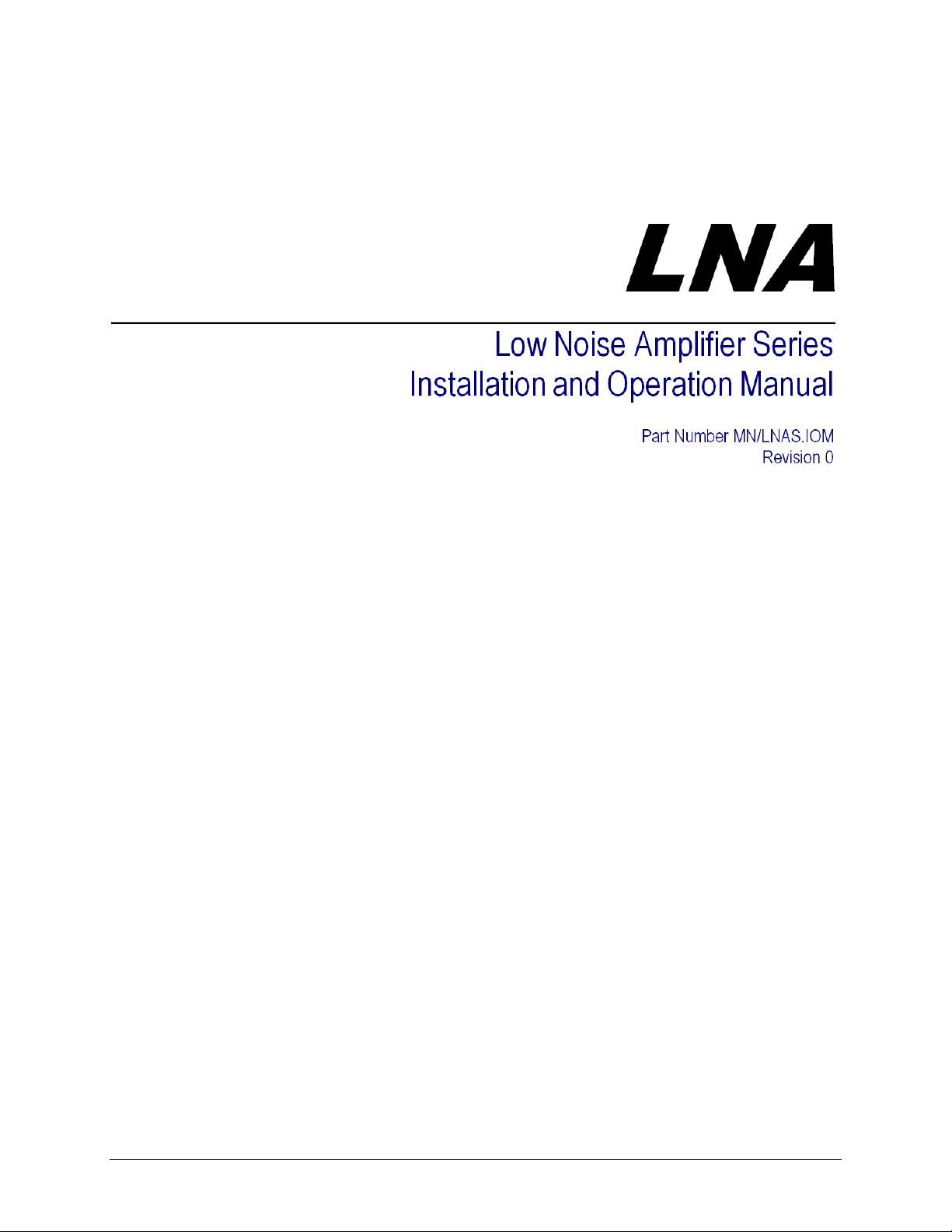
1. Sect.2.3LNAConnectorPinouts(pg2‐2)–ReplaceTable2‐1:
Was:
4-pin LNA 6-pin LNA
A: Power Input A: Power Input
B: This pin is reserved for
oven voltage
C: GND C: FLT – Normally Closed
D: GND D: FLT - Common
E: FLT – Normally Open
F: N/C
B: GND
Changeto:
Version ConnectorPinouts
4‐pinLNA A:PowerInput
B:GND
C,D:Alarm
6‐pinLNA–C‐Band A:PowerInput
B:GND
C:FLT–NormallyClosed
D:FLT‐Common
E:FLT–NormallyOpen
F:N/C
6‐pinLNA–Ku‐Band A:PowerInput
B,C:GND
D:FLT–NormallyClosed
E:Common
F:FLT–NormallyOpen
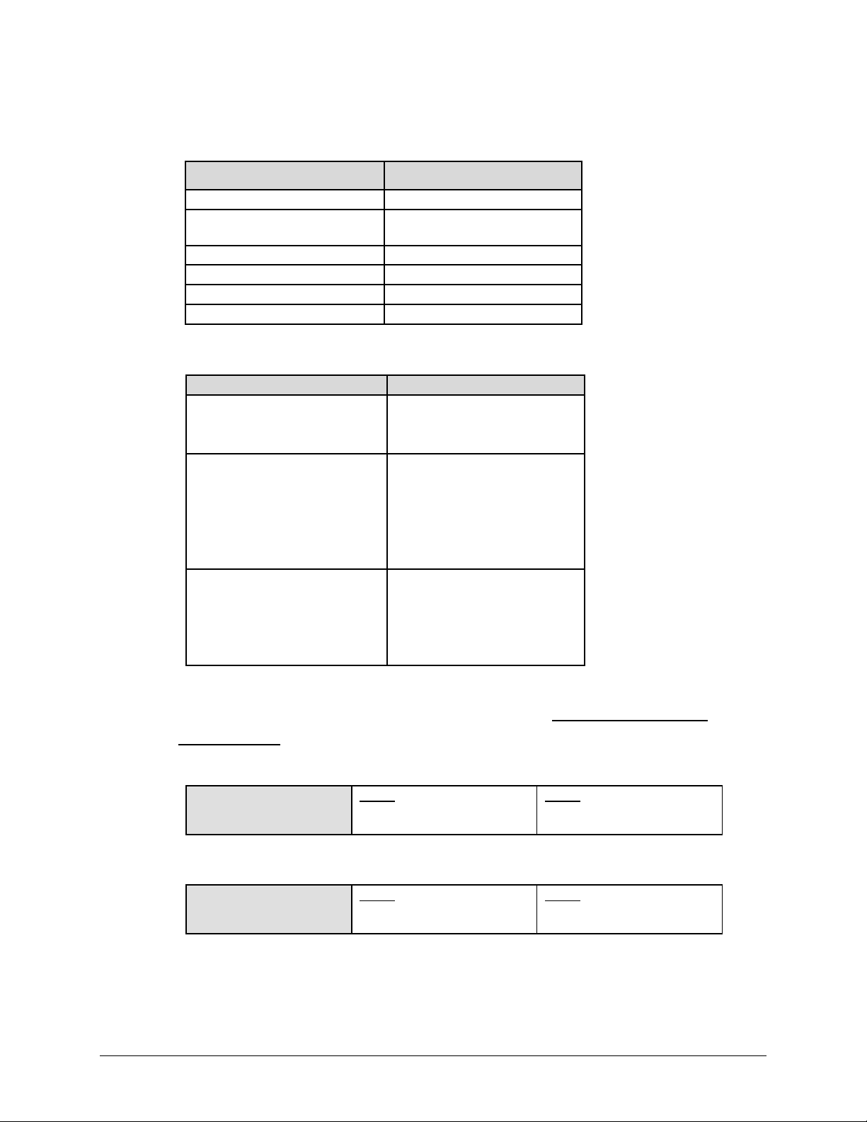
2. Sect.4.1SummaryofSpecifications(pg4‐1)–ReviseOverallStability(Over
Temperature)Specification:
Was:
Overall Stability (Over
Temperature)
CLNA
± 1 dB over Full Band
0.40 dB p-p over 40 MHz
KLNA
± 2 dB over Full Band
0.75 dB p-p over 40 MHz
Changeto:
Overall Stability (Over
Temperature)
CLNA
± 0.75 dB over Full Band
0.40 dB p-p over 40 MHz
ER-LNAS-EA0 THIS DOCUMENT IS NOT SUBJECT TO REVISION/UPDATE! PLM CO C-0024188 Page 2 of 2
KLNA
± 1.5 dB over Full Band
0.75 dB p-p over 40 MHz
Page 5

g
Comtech EF Data is an ISO 9001
Re
istered Company
Comtech EF Data, 2114 West 7th Street, Tempe, Arizona 85281 USA, 480.333.2200, FAX: 480.333.2161
i
LNA
Low Noise Amplifier Series
Installation and Operation Manual
Part Number MN/LNAS.IOM
Revision 0
December 14, 2005
Copyright © Comtech EF Data, 2004. All rights reserved. Printed in the USA.
Page 6

LNA Low Noise Amplifier Series Revision 0
Preface MN/LNAS.IOM
Customer Service
Contact the Comtech EF Data Customer Support Department for:
• Product support or training
• Information on upgrading or returning a product
• Reporting comments or suggestions concerning manuals
A Customer Support representative may be reached at:
Comtech EF Data
Attention: Customer Support Department
2114 West 7th Street
Tempe, Arizona 85281 USA
480.333.2200 (Main Comtech EF Data Number)
480.333.4357 (Customer Support Desk)
480.333.2161 FAX
or, E-Mail can be sent to the Customer Support Department at:
service@comtechefdata.com
Contact us via the web at www.comtechefdata.com
.
To return a Comtech EF Data product (in-warranty and out-of-warranty) for repair or
replacement:
• Request a Return Material Authorization (RMA) number from the Comtech EF Data
Customer Support Department.
• Be prepared to supply the Customer Support representative with the model number,
serial number, and a description of the problem.
• To ensure that the product is not damaged during shipping, pack the product in its
original shipping carton/packaging.
• Ship the product back to Comtech EF Data. (Shipping charges should be prepaid.)
For more information regarding the warranty policies, see Warranty Policy, p. ix.
ii
Page 7

Table of Contents
CHAPTER 1. INTRODUCTION .............................................................................................1–1
1.1 INTRODUCTION ........................................................................................................1–1
1.2 TECHNOLOGY ..........................................................................................................1–2
1.3 RELIABILITY ..............................................................................................................1–2
1.4 CONSTRUCTION.......................................................................................................1–2
CHAPTER 2. INSTALLATION ..............................................................................................2–1
2.1 UNPACKING..................................................................................................................2–1
2.2 MOUNTING.................................................................................................................... 2–2
2.3 LNA CONNECTOR PINOUTS .......................................................................................2–2
CHAPTER 3. FUNCTIONAL AND PHYSICAL DESCRIPTIONS .........................................3–1
3.1 DIMENSIONAL ENVELOPE ..........................................................................................3–1
3.1.1 C-Band LNA ...............................................................................................................3–1
3.1.2 Ku-Band LNA.............................................................................................................. 3–2
CHAPTER 4. SPECIFICATIONS...........................................................................................4–1
iii
Page 8

LNA Low Noise Amplifier Series Revision 0
Preface MN/LNAS.IOM
Figures
Figure 1-1. LNA Low Noise Amplifier Series............................................................................................1–1
Figure 1-2. LNA/710L Modulator Block Diagram .....................................................................................1–2
Figure 2-1. Installation of the Optional Mounting Bracket, KT/6228-2..................................................... 2–3
Figure 3-1. Front Panel ............................................................................................................................3–2
Figure 3-2. Dimensional Envelope...........................................................................................................3–3
Figure 4-1. Rear Panel.............................................................................................................................4–1
Figure 5-1. Front Panel View ...................................................................................................................5–1
Figure 5-2. Keypad................................................................................................................................... 5–3
Figure 5-3. LNA Menu Trees....................................................................................................................5–4
Figure 9-1. ASI And LVDS Interface Block Diagram ...............................................................................9–2
Figure 9-2. Rear Panel Layout................................................................................................................. 9–3
Figure 9-3. Signal Timing ......................................................................................................................... 9–5
Figure 10-1. 1000 Base-T Ethernet (GbE) Interface.............................................................................. 10–1
Figure 10-2. GbE Interface Option Board – Phase 1.............................................................................10–3
Tables
Table 4-1. Modem Rear Panel Connectorsfor 70/140 MHz Application.................................................. 4–2
Table 4-2. Modem Rear Panel Connectorsfor L-Band Application.......................................................... 4–2
Table 5-1. Front Panel LED Indicators..................................................................................................... 5–2
Table 5-2. Summary of Alarms Reported for Tx and Unit Categories ...................................................5–26
Table 5-3. Summary of Live Alarms....................................................................................................... 5–28
Table 7-1. ITU Legacy and DVB-S2 Modes.............................................................................................7–7
Table 10-1. Interface Specifications....................................................................................................... 10–2
Table 10-2. Connector Pinout ................................................................................................................10–4
iv
Page 9

LNA Low Noise Amplifier Series Revision 0
Preface MN/LNAS.IOM
Preface
About this Manual
This manual provides installation and operation information for the Comtech EF Data LNA Low
Noise Amplifier Series. This is a technical document intended for earth station engineers,
technicians, and operators responsible for the operation and maintenance of the LNA.
Conventions and References
Metric Conversion
Metric conversion information is located on the inside back cover of this manual. This
information is provided to assist the operator in cross-referencing English to Metric conversions.
Cautions and Warnings
CAUTION indicates a hazardous situation that, if not avoided, may result in
minor or moderate injury. CAUTION may also be used to indicate other
CAUTION
WARN ING
IMPORTANT
unsafe practices or risks of property damage.
WARNING indicates a potentially hazardous situation that,
if not avoided, could result in death or serious injury.
Indicates information critical for proper equipment
function.
Reporting Comments or Suggestions Concerning this Manual
Comments and suggestions regarding the content and design of this manual will be appreciated.
To submit comments, please contact the Comtech EF Data Technical Publications Department:
techpub@comtechefdata.com
v
Page 10

LNA Low Noise Amplifier Series Revision 0
Preface MN/LNAS.IOM
Electrical Safety
The LNA Low Noise Amplifier Series has been shown to comply with the following safety
standard:
• EN 60950: Safety of Information Technology Equipment, including electrical
business machines
The equipment is rated for operation over the range 100 - 240 volts AC. It has a maximum power
consumption of 60 watts, and draws a maximum of 600 mA.
The user should observe the following instructions:
IMPORTANT
Fuses
The LNA is fitted with two fuses - one each for line and neutral connections. These are contained
within the body of the IEC power inlet connector, behind a small plastic flap.
• For 115 and 230 volt AC operation, use T1.25A, 20mm fuses.
FOR CONTINUED OPERATOR SAFETY, ALWAYS REPLACE THE FUSES WITH
THE CORRECT TYPE AND RATING.
Environmental
The LNA must not be operated in an environment where the unit is exposed to extremes of
temperature outside the ambient range 0 to 50°C (32° to 122°F), precipitation, condensation, or
humid atmospheres above 95% RH, altitudes (un-pressurized) greater than 2000 metres,
excessive dust or vibration, flammable gases, corrosive or explosive atmospheres.
Operation in vehicles or other transportable installations that are equipped to provide a stable
environment is permitted. If such vehicles do not provide a stable environment, safety of the
equipment to EN60950 may not be guaranteed.
Installation
The installation and connection to the line supply must be made in compliance to local or national
wiring codes and regulations.
vi
Page 11

LNA Low Noise Amplifier Series Revision 0
Preface MN/LNAS.IOM
The LNA is designed for connection to a power system that has separate ground, line and neutral
conductors. The equipment is not designed for connection to power system that has no direct
connection to ground.
The LNA is shipped with a line inlet cable suitable for use in the country of operation. If it is
necessary to replace this cable, ensure the replacement has an equivalent specification. Examples
of acceptable ratings for the cable include HAR, BASEC and HOXXX-X. Examples of
acceptable connector ratings include VDE, NF-USE, UL, CSA, OVE, CEBEC, NEMKO,
DEMKO, BS1636A, BSI, SETI, IMQ, KEMA-KEUR and SEV.
International Symbols:
Symbol Definition Symbol Definition
~
Alternating Current
Fuse
Telecommunications Terminal Equipment Directive
In accordance with the Telecommunications Terminal Equipment Directive 91/263/EEC, this
equipment should not be directly connected to the Public Telecommunications Network.
Protective Earth
Chassis Ground
vii
Page 12

LNA Low Noise Amplifier Series Revision 0
Preface MN/LNAS.IOM
EMC (Electromagnetic Compatibility)
In accordance with European Directive 89/336/EEC, the LNA Modem has been shown, by
independent testing, to comply with the following standards:
Emissions: EN 55022 Class B - Limits and methods of measurement of radio interference
characteristics of Information Technology Equipment.
(Also tested to FCC Part 15 Class B)
Immunity: EN 50082 Part 1 - Generic immunity standard, Part 1: Domestic, commercial and
light industrial environment.
Additionally, the LNA has been shown to comply with the following standards:
EN 61000-3-2 Harmonic Currents Emission
EN 61000-3-3 Voltage Fluctuations and Flicker
EN 61000-4-2 ESD Immunity
EN 61000-4-4 EFT Burst Immunity
EN 61000-4-5 Surge Immunity
EN 61000-4-6 RF Conducted Immunity
EN 61000-4-8 Power Frequency Magnetic Field Immunity
EN 61000-4-9 Pulse Magnetic Field Immunity
EN 61000-4-11 Voltage Dips, Interruptions, and Variations Immunity
EN 61000-4-13 Immunity to Harmonics
In order that the Modem continues to comply with these
standards, observe the following instructions:
IMPORTANT
• Connections to the Tx and Rx IF ports (Type N or Type F connectors) should be
made using a good quality coaxial cable - for example 50 Ω or 75 Ω.
• All 'D' type connectors attached to the rear panel must have back-shells that provide
continuous metallic shielding. Cable with a continuous outer shield (either foil or
braid, or both) must be used, and the shield must be bonded to the backshell.
• The equipment must be operated with its cover on at all times. If it becomes
necessary to remove the cover, the user should ensure that the cover is correctly refitted before normal operation commences.
viii
Page 13

LNA Low Noise Amplifier Series Revision 0
Preface MN/LNAS.IOM
Warranty Policy
This Comtech EF Data product is warranted against defects in material and workmanship for a
period of two years from the date of shipment. During the warranty period, Comtech EF Data
will, at its option, repair or replace products that prove to be defective.
For equipment under warranty, the customer is responsible for freight to Comtech EF Data and all
related custom, taxes, tariffs, insurance, etc. Comtech EF Data is responsible for the freight
charges only for return of the equipment from the factory to the customer. Comtech EF Data will
return the equipment by the same method (i.e., Air, Express, Surface) as the equipment was sent
to Comtech EF Data.
Limitations of Warranty
The foregoing warranty shall not apply to defects resulting from improper installation or
maintenance, abuse, unauthorized modification, or operation outside of environmental
specifications for the product, or, for damages that occur due to improper repackaging of
equipment for return to Comtech EF Data.
No other warranty is expressed or implied. Comtech EF Data specifically disclaims the implied
warranties of merchantability and fitness for particular purpose.
Exclusive Remedies
The remedies provided herein are the buyer's sole and exclusive remedies. Comtech EF Data shall
not be liable for any direct, indirect, special, incidental, or consequential damages, whether based
on contract, tort, or any other legal theory.
Disclaimer
Comtech EF Data has reviewed this manual thoroughly in order that it will be an easy-to-use
guide to your equipment. All statements, technical information, and recommendations in this
manual and in any guides or related documents are believed reliable, but the accuracy and
completeness thereof are not guaranteed or warranted, and they are not intended to be, nor should
they be understood to be, representations or warranties concerning the products described.
Further, Comtech EF Data reserves the right to make changes in the specifications of the products
described in this manual at any time without notice and without obligation to notify any person of
such changes.
If you have any questions regarding your equipment or the information in this manual, please
contact the Comtech EF Data Customer Support Department.
ix
Page 14

LNA Low Noise Amplifier Series Revision 0
Preface MN/LNAS.IOM
Notes:
______________________________________________________________________________
______________________________________________________________________________
______________________________________________________________________________
______________________________________________________________________________
______________________________________________________________________________
______________________________________________________________________________
______________________________________________________________________________
______________________________________________________________________________
______________________________________________________________________________
______________________________________________________________________________
______________________________________________________________________________
______________________________________________________________________________
______________________________________________________________________________
______________________________________________________________________________
______________________________________________________________________________
______________________________________________________________________________
______________________________________________________________________________
______________________________________________________________________________
______________________________________________________________________________
______________________________________________________________________________
______________________________________________________________________________
______________________________________________________________________________
______________________________________________________________________________
______________________________________________________________________________
______________________________________________________________________________
______________________________________________________________________________
______________________________________________________________________________
______________________________________________________________________________
______________________________________________________________________________
______________________________________________________________________________
______________________________________________________________________________
______________________________________________________________________________
______________________________________________________________________________
______________________________________________________________________________
______________________________________________________________________________
______________________________________________________________________________
______________________________________________________________________________
______________________________________________________________________________
______________________________________________________________________________
______________________________________________________________________________
______________________________________________________________________________
______________________________________________________________________________
x
Page 15

Chapter 1. INTRODUCTION
1.1 Introduction
The Comtech EF Data (CEFD) Low-Noise Amplifier (LNA) series (Figure 1-1) includes LNAs,
available in C-Band and Ku-Band. They meet or exceed system requirements for commercial
geosynchronous satellites worldwide. Their compact design and rugged construction make them
ideal for transportable applications and severe environments. They have a comprehensive set of
options to accom-modate systems ranging from Very Small Amplifier Terminal (VSATs) to
major earth stations.
C-Band Low-Noise Amplifier
-
Figure 1-1. LNA
1–1
-
Page 16

LNA Low-Noise Amplifier Series Revision 0
Introduction MN/LNAS.IOM
1.2 TECHNOLOGY
The amplifiers incorporate both HEMT (High Electron Mobility Transistors) devices for LowNoise temperature performance and GaAs FET (Gallium Arsenide) devices for low
intermodulation. The unit uses surface mounted components for robotic manufacturing
techniques, thereby insuring maximum product consistency and enhanced reliability.
1.3 RELIABILITY
The Comtech EF Data amplifier series (CLNA and KLNA) utilizes proprietary circuitry and high
quality components to achieve an MTBF (mean time between failures) in excess of 160,000
hours. Each unit is subjected to a 72 hour burn-in and temperature cycled from -40 to 140°F
(-40 to +60°C).
1.4 CONSTRUCTION
The LNAs (CLNA and KLNA) are housed in waterproof enclosures with a small profiles to
better accommodate redundancy configurations. The enclosures also provide a pressurizable,
integral waveguide flange.
1–2
Page 17

2.1 Unpacking
Inspect shipping containers for damage. If shipping containers are damaged, keep them until the
contents of the shipment have been carefully inspected and checked for normal operation.
The modulator and manual are packaged in pre-formed, reusable, cardboard cartons containing
foam spacing for maximum shipping protection.
CAUTION
Unpack the LNA as follows:
Step Procedure
1 Cut the tape at the top of the carton indicated by OPEN THIS END.
2 Remove the cardboard/foam space covering the LNA.
3 Remove the LNA, and manual from the carton.
4 Save the packing material for storage or reshipment purposes.
5 Inspect the equipment for any possible damage incurred during shipment.
6 Check the equipment against the packing list to ensure the shipment is correct.
7 Refer to the following sections for further installation instructions.
Chapter 2. INSTALLATION
Do not use any cutting tool that will extend more than 1 inch into the
container. This can cause damage to the LNA.
2–1
Page 18

LNA Low Noise Amplifier Series Revision 0
Installation MN/LNAS.IOM
2.2 Mounting
No special tools are required.
2.3 LNA Connector Pinouts
LNA can be supplied with the following connector configurations, depending on the
model and options:
• 4 pin
• 6 pin
See Table 2-1 for pinouts of the above connectors.
Table 2-1. LNA Connector Pinouts
4-Pin LNA 6-Pin LNA
A: Power Input A: Power Input
B: This pin is reserved for
oven voltage
C: GND C: FLT – Normally Closed
D: GND D: FLT – Common
E: FLT – Normally Open
F: N/C
B: GND
2–2
Page 19

Chapter 3. FUNCTIONAL AND
PHYSICAL DESCRIPTIONS
3.1 Dimensional Envelope
All dimensions are in English units (centimeters are in parentheses).
3.1.1 C-Band LNA
Figure 3-1. C-Band LNA Dimensions
3–1
Page 20

CDM-710 Satellite Modulator Revision 2
)
Functional and Physical Description MN/CDM710.IOM
3.1.2 Ku-Band LNA
(1.63)
(.25)
(1.122)
(.38)
(1.80)
(1.040
Figure 3-2. Ku-Band LNA Dimensions
3–2
Page 21

Chapter 4. SPECIFICATIONS
4.1 Summary of Specifications
Frequency CLNA
3.4 to 4.2 GHz
3.625 to 4.2 GHz
4.5 to 4.8 GHz
Noise Temperature CLNA
30, 35, 40, 45K
Gain
Overall Stability (Over
Temperature)
Level @ 1 dB Comp.
Third Order Intercept
AM-PM Conversion
Linear Group Delay
Parabolic Group Delay
Ripple
Input/Output VSWR
Input Waveguide CLNA
Output Connector
Operating Temp.
Input Power
Power Connector CLNA
50, 60 dB
CLNA
± 1 dB over Full Band
0.40 dB p-p over 40 MHz
+10 dBm
+20 dBm
0.5°/dB @ -5 dBm
0.01 ns/MHz
0.001 ns/MHz2
0.1 ns p-p
1.25:1 max.
CPR229
Type N Standard, Optional SMA
-40 to +140°F (-40 to +60°C)
+12 to +24 VDC @ 120 mA
Coaxial or PTA02A-9-4P
KLNA
10.95 to 12.75 GHz
KLNA
80, 85K
KLNA
± 2 dB over Full Band
0.75 dB p-p over 40 MHz
KLNA
WR75
KLNA
Coaxial and 4-Pin
4–1
Page 22

LNA Low Noise Amplifier Series Revision 0
Specifications MN/LNAS.IOM
Notes:
_____________________________________________________________________________________________
_____________________________________________________________________________________________
_____________________________________________________________________________________________
_____________________________________________________________________________________________
_____________________________________________________________________________________________
_____________________________________________________________________________________________
_____________________________________________________________________________________________
_____________________________________________________________________________________________
_____________________________________________________________________________________________
_____________________________________________________________________________________________
_____________________________________________________________________________________________
_____________________________________________________________________________________________
_____________________________________________________________________________________________
_____________________________________________________________________________________________
_____________________________________________________________________________________________
_____________________________________________________________________________________________
_____________________________________________________________________________________________
_____________________________________________________________________________________________
_____________________________________________________________________________________________
_____________________________________________________________________________________________
_____________________________________________________________________________________________
_____________________________________________________________________________________________
_____________________________________________________________________________________________
_____________________________________________________________________________________________
_____________________________________________________________________________________________
_____________________________________________________________________________________________
_____________________________________________________________________________________________
_____________________________________________________________________________________________
_____________________________________________________________________________________________
_____________________________________________________________________________________________
_____________________________________________________________________________________________
_____________________________________________________________________________________________
_____________________________________________________________________________________________
_____________________________________________________________________________________________
_____________________________________________________________________________________________
_____________________________________________________________________________________________
_____________________________________________________________________________________________
_____________________________________________________________________________________________
_____________________________________________________________________________________________
_____________________________________________________________________________________________
_____________________________________________________________________________________________
_____________________________________________________________________________________________
_____________________________________________________________________________________________
_____________________________________________________________________________________________
_____________________________________________________________________________________________
_____________________________________________________________________________________________
_____________________________________________________________________________________________
_____________________________________________________________________________________________
_____________________________________________________________________________________________
_____________________________________________________________________________________________
_____________________________________________________________________________________________
_____________________________________________________________________________________________
_____________________________________________________________________________________________
_____________________________________________________________________________________________
_____________________________________________________________________________________________
_____________________________________________________________________________________________
4–2
Page 23

METRIC CONVERSIONS
Units of Length
Unit
1 centimeter — 0.3937 0.03281 0.01094
1 inch 2.540 — 0.08333 0.2778
1 foot 30.480 12.0 — 0.3333
1 yard 91.44 36.0 3.0 —
Centimeter
Inch
Foot
Yard
Mile
6.214 x 10
1.578 x 10
1.893 x 10
5.679 x 10
Meter
-6
-5
-4
-4
0.01 — —
0.254 — 25.4
0.3048 — —
0.9144 — —
Kilometer Millimeter
1 meter 100.0 39.37 3.281 1.094
1 mile
1 mm — 0.03937 — — — — — —
1 kilometer — — — — 0.621 — — —
1.609 x 10
5
6.336 x 10⁴ 5.280 x 10³ 1.760 x 10³
6.214 x 10
-4
—
— — —
1.609 x 10³
1.609 —
Temperature Conversions
Unit
32° Fahrenheit
212° Fahrenheit
-459.6° Fahrenheit
° Fahrenheit
—
—
—
° Centigrade
0
(water freezes)
100
(water boils)
273.1
(absolute 0)
Formulas
C = (F - 32) * 0.555
F = (C * 1.8) + 32
Units of Weight
Unit
1 gram — 0.03527 0.03215 0.002205 0.002679 0.001
Gram
Ounce
Avoirdupois
Ounce
Troy
Pound
Avoir.
Pound
Troy
Kilogram
1 oz. avoir. 28.35 — 0.9115 0.0625 0.07595 0.02835
1 oz. troy 31.10 1.097 — 0.06857 0.08333 0.03110
1 lb. avoir. 453.6 16.0 14.58 — 1.215 0.4536
1 lb. Troy 373.2 13.17 12.0 0.8229 — 0.3732
1 kilogram
1.0 x 10
3
35.27 32.15 2.205 2.679 —
Page 24

2114 WEST 7TH STREET TEMPE ARIZONA 85281 USA
480 • 333 • 2200 PHONE
480 • 333 • 2161
FAX
 Loading...