

Page 1

r
d
Ku-Band Power Amplifie
with Optional L-Ban
Operation Manual
IMPORTANT NOTE: The information contained in this document supersedes all previously published
information regarding this product. Product specifications are subject to change without prior notice.
Part Number MN/ODPA.OM Revision 0
Page 2

Page 3
Comtech EF Data Documentation Update
Subject:
Date:
Original Document
Part Number/Rev:
Errata
Part Number:
Change Specifics:
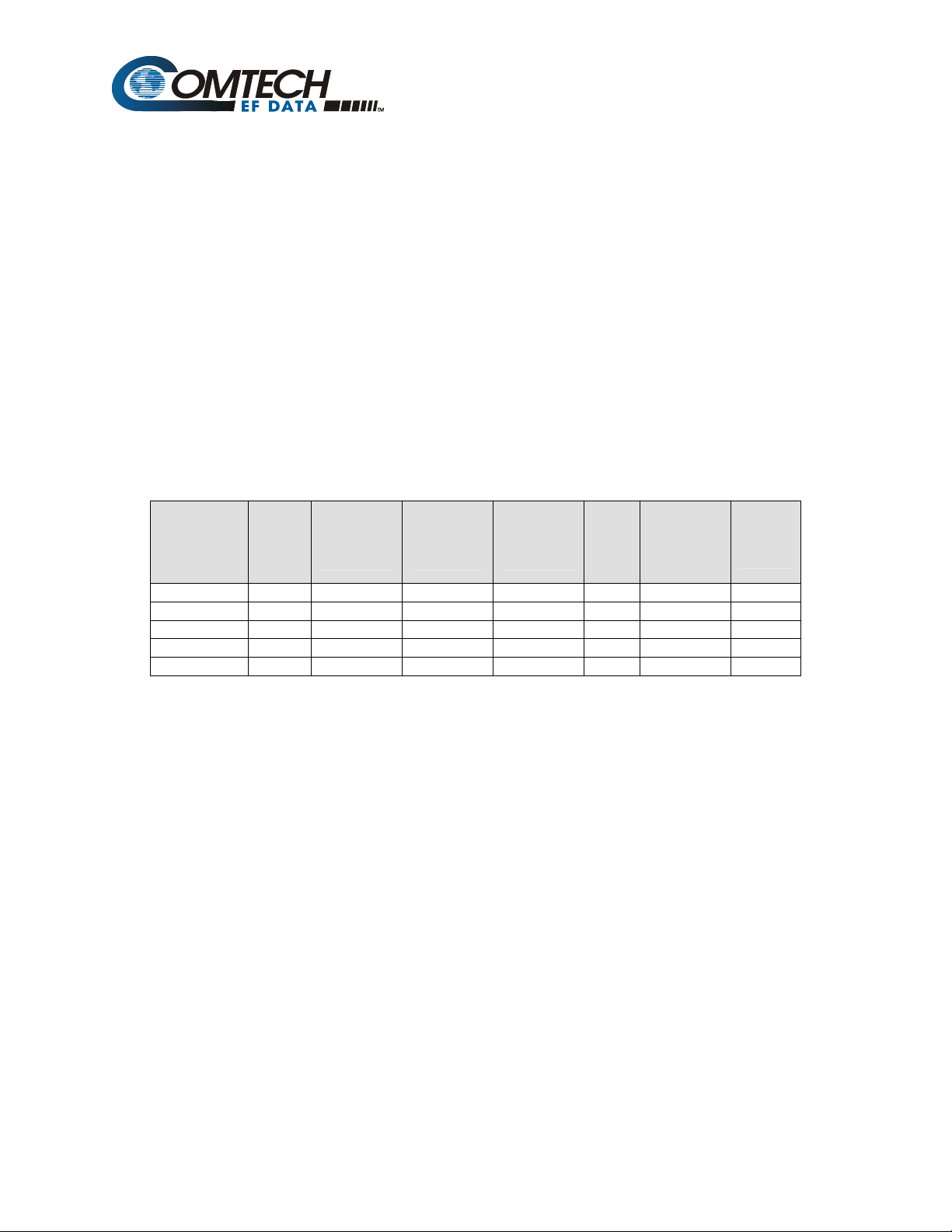
Add Table 3-1.
Table 3-1. LO, MIX and Mod Spectrum Settings for Modulator And BUC
Errata A
Changes to Chapter 3 Operation
April 26, 2006
MN/ODPA.IOM Rev 0
MN/ODPA.EA0
This information will be incorporated into the next revision.
P1dB_min
8 Watt Ku 14.00 14.50 13,050.00 + Normal 24 VDC
16 Watt Ku 14.00 14.50 13,050.00 + Normal 24 VDC
25 Watt Ku 14.00 14.50 13,050.00 + Normal 24VDC
32 Watt Ku 14.00 14.50 13,050.00 + Normal 24VDC
40 Watt Ku 14.00 14.50 13,050.00 + Normal 24 VDC
Band
RF Start
Frequency
(GHz)
RF End
Frequency
(GHz)
LO (Offset)
Freq.
(MHz)
Mix
(+/-)
Modem
Spectrum
(Utility
Modulator
Menu)
BUC
Supply
Voltage
s:\tpubs\manuals\released_word\amplifiers\odpa ku-band\errata a.doc
1
Page 4

s:\tpubs\manuals\released_word\amplifiers\odpa ku-band\errata a.doc
2
Page 5

Errata B
Comtech EF Data Documentation Update
Subject:
Date:
Original Document
Part Number/Rev:
Errata
Part Number:
Change Specifics:
This information will be incorporated into the next revision.
Replace 32/40 Watt ODPA Equipment Outline (Non L-Band)
Dimensional Drawing
November 24, 2004
MN/ODPA.IOM Rev 0
MN/ODPA.EB0
Replace Figure A-4, page A-5 with the following:
s:\tpubs\manuals\released_word\sspas\odpa ku-band\errata b.doc
1
Page 6
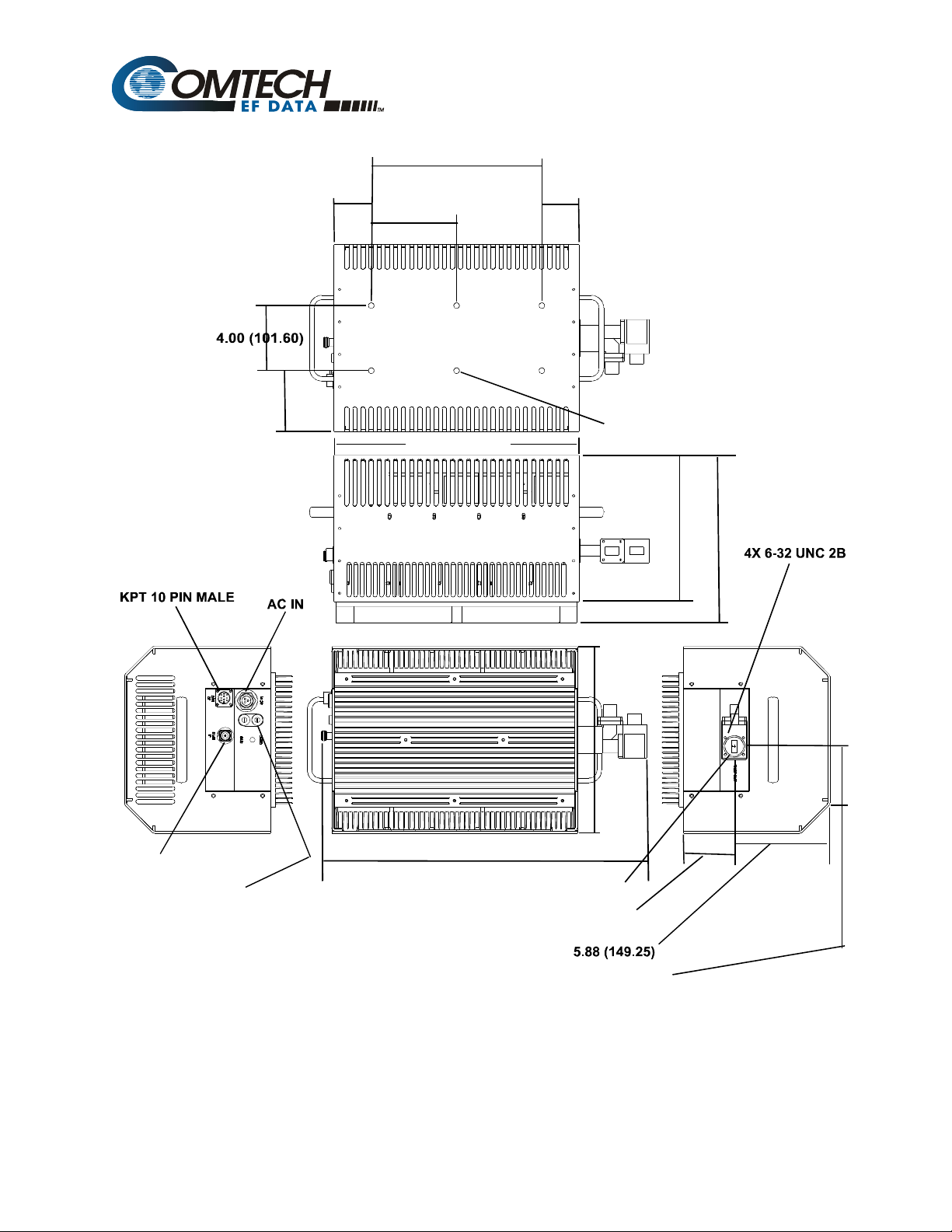
10.50 (266.70)
2.30 (58.42) 2.30 (58.42)
3.75 (95.25)
5.25 (133.35)
6X 1/4-20 x.375 DP
15.10 (383.54)
9.0 0 (288.60)
10.31 (261.90)
“N” RF IN
2X FUSE HOLDERS
11.50 (292.10)
20.03 (508.76)
WR 75 WAVEGUIDE GROOVED
3.12 (79.35)
5.35 (35.89)
s:\tpubs\manuals\released_word\sspas\odpa ku-band\errata b.doc
2
Page 7

Ku-Band Power Amplifier with
Optional L-Band
Operation Manual
Part Number MN/ODPA.OM
Comtech EF Data is an ISO 9001
Registered Company.
October 4, 2004
Copyright © Comtech EF Data, 2001. All rights reserved. Printed in the USA.
Comtech EF Data, 2114 West 7th Street, Tempe, Arizona 85281 USA, 480.333.2200, FAX: 480.333.2161.
Revision 0
Page 8

Customer Support
Contact the Comtech EF Data Customer Support Department for:
• Product support or training
• Information on upgrading or returning a product
• Reporting comments or suggestions concerning manuals
A Customer Support representative may be reached at:
Comtech EF Data
Attention: Customer Support Department
2114 West 7th Street
Tempe, Arizona 85281 USA
480.333.2200 (Main Comtech EF Data Number)
480.333.4357 (Customer Support Desk)
480.333.2161 FAX
or, E-Mail can be sent to the Customer Support Department at:
service@comtechefdata.com
Contact us via the web at www.comtechefdata.com
1. To return a Comtech EF Data product (in-warranty and out-of-warranty) for
repair or replacement:
2. Request a Return Material Authorization (RMA) number from the Comtech EF
Data Customer Support Department.
3. Be prepared to supply the Customer Support representative with the model
number, serial number, and a description of the problem.
4. To ensure that the product is not damaged during shipping, pack the product in
its original shipping carton/packaging.
5. Ship the product back to Comtech EF Data. (Shipping charges should be
prepaid.)
For more information regarding the warranty policies, see Warranty Policy, p. vii.
.
ii
Page 9

Table of Contents
CHAPTER 1. INTRODUCTION .......................................................................................................... 1-1
1.1 Description .................................................................................................................................................1-1
1.2 System Block Diagram ..............................................................................................................................1-2
1.3 Functional Description .............................................................................................................................. 1-2
1.4
Specifications.............................................................................................................................................. 1-2
CHAPTER 2. MOUNTING .................................................................................................................. 2-1
2.1 Installation..................................................................................................................................................2-1
2.2 Mounting Kit PL/7725-1/-2.......................................................................................................................2-1
2.3 Mounting Kit PL/8094-1 ...........................................................................................................................2-4
2.4
External Connectors..................................................................................................................................2-6
CHAPTER 3. OPERATION ................................................................................................................ 3-1
3.1 Operation.................................................................................................................................................... 3-1
3.2 M&C Pinout Configuration...................................................................................................................... 3-1
3.3 Theory of Operation..................................................................................................................................3-2
APPENDIX A. EQUIPMENT OUTLINE DRAWING.............................................................................A-1
iii
Page 10

Outdoor Power Amplifier Revision 0
Preface MN/ODPA.OM
This page is intentionally left blank.
iv
Page 11

Outdoor Power Amplifier Revision 0
Preface MN/ODPA.OM
About this Manual
This manual provides installation and operation information for the Comtech EF Data
Ku-Band Power Amplifier with Optional L-Band, herein after referred as the Outdoor
Power Amplifier (ODPA). This is a technical document intended for earth station
engineers, technicians, and operators responsible for the operation and maintenance of
the ODPA.
Safety Notices
This equipment has been designed to minimize exposure of personnel to hazards. The
operators and technicians must:
• Know how to work around, with, and on high voltage and high RF power
level equipment.
WARN ING
• Exercise every precaution to ensure personnel safety.
• Exercise extreme care when working near high voltages/high RF power
level equipment.
• Be familiar with the warning presented in this manual.
• Disconnect the power supply cord before servicing the SSPA.
Lithium Battery Replacement
There is a possibility that the Lithium battery on the M&C assembly will
explode if the battery is incorrectly replaced. Observe all instructions from
WARN ING
the battery manufacturer. Replace only with the same or equivalent type
battery recommended by the manufacturer. Dispose of used batteries
according to the Lithium battery manufacturer’s instructions.
Metric Conversion
Metric conversion information is located on the inside back cover of this manual. This
information is provided to assist the operator in cross-referencing English to Metric
conversions.
Trademarks
Windows is a trademark of the Microsoft Corporation.
Other product names mentioned in this manual may be trademarks or registered
trademarks of their respective companies and are hereby acknowledged.
v
Page 12

Outdoor Power Amplifier Revision 0
Preface MN/ODPA.OM
Reporting Comments or Suggestions Concerning this Manual
Comments and suggestions regarding the content and design of this manual will be
appreciated. To submit comments, please contact the Comtech EF Data Technical
Publications Department: techpubs@comtechefdata.com
European EMC Directive
In order to meet the European Electro-Magnetic Compatibility (EMC) Directive
(EN55022, EN50082-1), properly shielded cables for DATA I/O are required. More
specifically, these cables must be shielded from end-to-end, ensuring a continuous
ground shield.
The following information is applicable for the European Low Voltage Directive
(EN60950):
<HAR> Type of power cord required for use in the European Community.
CAUTION: Double-pole/Neutral Fusing
!
International Symbols:
ACHTUNG: Zweipolige bzw. Neutralleiter-Sicherung
Alternating Current.
Fuse.
Safety Ground.
Chassis Ground.
Note: For additional symbols, refer to “Cautions and Warnings” listed earlier in this
preface.
vi
Page 13

Outdoor Power Amplifier Revision 0
Preface MN/ODPA.OM
Warranty Policy
This Comtech EF Data product is warranted against defects in material and workmanship
for a period of 2 years from the date of shipment. During the warranty period, Comtech
EF Data will, at its option, repair or replace products that prove to be defective.
For equipment under warranty, the customer is responsible for freight to Comtech EF
Data and all related custom, taxes, tariffs, insurance, etc. Comtech EF Data is responsible
for the freight charges only for return of the equipment from the factory to the customer.
Comtech EF Data will return the equipment by the same method (i.e., Air, Express,
Surface) as the equipment was sent to Comtech EF Data.
Limitations of Warranty
The foregoing warranty shall not apply to defects resulting from improper installation or
maintenance, abuse, unauthorized modification, or operation outside of environmental
specifications for the product, or, for damages that occur due to improper repackaging of
equipment for return to Comtech EF Data.
No other warranty is expressed or implied. Comtech EF Data specifically disclaims the
implied warranties of merchantability and fitness for particular purpose.
Exclusive Remedies
The remedies provided herein are the buyer's sole and exclusive remedies. Comtech EF
Data shall not be liable for any direct, indirect, special, incidental, or consequential
damages, whether based on contract, tort, or any other legal theory.
Disclaimer
Comtech EF Data has reviewed this manual thoroughly in order that it will be an easy-touse guide to your equipment. All statements, technical information, and
recommendations in this manual and in any guides or related documents are believed
reliable, but the accuracy and completeness thereof are not guaranteed or warranted, and
they are not intended to be, nor should they be understood to be, representations or
warranties concerning the products described. Further, Comtech EF Data reserves the
right to make changes in the specifications of the products described in this manual at any
time without notice and without obligation to notify any person of such changes.
If you have any questions regarding your equipment or the information in this manual,
please contact the Comtech EF Data Customer Support Department.
vii
Page 14

Outdoor Power Amplifier Revision 0
Preface MN/ODPA.OM
Notes:
________________________________________________________________________
________________________________________________________________________
________________________________________________________________________
________________________________________________________________________
________________________________________________________________________
________________________________________________________________________
________________________________________________________________________
________________________________________________________________________
________________________________________________________________________
________________________________________________________________________
________________________________________________________________________
________________________________________________________________________
________________________________________________________________________
________________________________________________________________________
________________________________________________________________________
________________________________________________________________________
________________________________________________________________________
________________________________________________________________________
________________________________________________________________________
________________________________________________________________________
________________________________________________________________________
________________________________________________________________________
________________________________________________________________________
________________________________________________________________________
________________________________________________________________________
________________________________________________________________________
________________________________________________________________________
________________________________________________________________________
________________________________________________________________________
________________________________________________________________________
________________________________________________________________________
________________________________________________________________________
________________________________________________________________________
________________________________________________________________________
________________________________________________________________________
________________________________________________________________________
________________________________________________________________________
________________________________________________________________________
________________________________________________________________________
________________________________________________________________________
________________________________________________________________________
________________________________________________________________________
viii
Page 15

Chapter 1. Introduction
1.1 Description
The Ku-Band Outdoor Power Amplifier (ODPA) provides higher output power than
typically available in a block package. The optional L-Band Up Converter requires 24
VDC and a 10 MHz reference on the coax from an L-band modem.
Figure 1-1. 25-40 Watt High Power Ku-Band BUC
1–1
Page 16

Outdoor Power Amplifier Revision 0
Introduction MN/ODPA.OM
The SSPA portion is line powered and provides an analog interface for fault status and
mute control.
The ODPA delivers up to 40 Watts, at the 1 dB compression point, to the transmit
waveguide flange. It provides a cost-effective and reliable replacement for TWT
amplifiers in Ku-Band terminals. Due to a small form factor, it is ideal for the
construction of small “flyaway” terminals, Intelsat earth stations, and hub earth stations
for small- to medium-size private networks or point-to-point links.
1.2 System Block Diagram
10 MHz, DC, L-Band
L-Band
X
DC
PLL
10 MHz
Ku-BUC
AC
Figure 1-2. System Block Diagram
1.3 Functional Description
The ODPA consists of a chassis, power supply, fan assembly, Monitor and Control
Processor (MCP) and a Comtech EF Data SSPA module. The amplifier is designed using
a Comtech EF Data low loss combining technique and an MCP based temperature versus
gain compensation.
14.0 - 14.5 GHz
40W - SSPA
1–2
Page 17

Outdoor Power Amplifier Revision 0
Introduction MN/ODPA.OM
1.4 Specification
Characteristics
Input Frequency - IF 950 to 1450 MHz
Output Frequency Range 14.00 – 14.50 GHz
Optional: 13.75 to 14.50 GHz
Max. Input Power without damage (ODPA) +15 dBm
Gain Flatness over Full Band (ODPA) ± 1.0 dB max
(ODPA w/L-Band) ± 2.5 dB nominal
Gain Variation over 36Mhz ± 1.0 dB
Gain Variation (ODPA) ± 1.0 dB over operating temperature range
Gain Stability over Temperature (ODPA w/L-Band) ±2.5 dB
Gain Slope (ODPA) 0.5 dB/40 MHz max
Noise Figure at max Gain 10 dB
Power Output @1dB
Compression @ 25°C: 8W +39dBm
16W +42 dBm
25W +44 dBm
32W +45 dBm
40W +46 dBm
rd
3
Order Intercept Point: 8W +47 dBm
16W +50 dBm
25W +52 dBm
32W +53 dBm
40W +54 dBm
rd
3
Order IMD: -34 dBc @ 6dB backoff (SCL 9 dB backoff from P1 dB)
-28 dBc @ 3dB backoff (SCL 6 dB backoff from P1dB)
Input/Output Return Loss 18 dB minimum
Spurious (in-band) at Rated Power (ODPA) -50 dBc maximum
Spurious at Rated Power (ODPA) –65 dBc max
Spurious (Rx band) at Rated Power -70 dBc maximum
Harmonics at Rated Power (ODPA) –65 dBc max
AM/PM Conversion (ODPA) 2.5°/dB typical (@P1dB) and 3.0°/dB max
Group Delay:
Linear 0.02 nsec/NHz
Parabolic 0.003 nsec MHz
Ripple 1 nsec peak-to-peak
RF-Mute -60 dB
ODPA
8W +33 dB
16W +36 dB
25W +40 dB
32W +42 dB
40W +44 dB
ODPA w/L-Band
8W + 63 dB
16W +66 dB
25W +68 dB
32W +69 dB
40W +70 dB
2
Phase Noise Limit (dBc/Hz)
300 Hz offset -60
1 kHz offset -70
10 kHz offset -80
100 kHz offset -90
1 MHz offs -100
Front Panel
Display 20 x 2 LCD
Data Entry Cursor Control Keypad
Output Sample Type N, 50 Ω, -40 dBc
Required External Reference Signal
Required External Reference Signal Frequency: 10 MHz
Input Power: -5 to +5 dBm
Phase Noise: -125 dBc/Hz max. @ 100Hz
-135 dBc/Hz max. @ 1 kHz
-140 dBc/Hz max. @ 10 kHz
L-Band (Optional)
Power Requirement: +15 to +24 VDC
Power Consumption: 1.6 A max. @ +15V
System Power Requirements
ODPA Input Power. 85 - 264 VAC, 47 - 63 Hz 8W 150W
16W 180W
25W 360W
AC Input Voltage 110/220 VAC ± 15% (47 to 63Hz)
Auto Ranging, 12, 24, & 48 are optional)
Mechanical Requirements
Interface: IF Input Type N (F optional)
RF Output WR75 *
M&C Analogue MS3112E16-26P *
Power (ODPA) MS3102R16-10P *
Molex Custom (#84855 Series)
*Other options are available
Environmental
Temperature:
Operating -40º to 55º C. (-40º to 122º F)
Storage (ODPA) -55º to 75º C (-67º to 167º F)
Humidity 100% condensing rain 2” per hour
Altitude 10,000 AMSL
Shock Normal commercial shipping and Handling
Physical
Dimensional :
8 and 16 Watt ODPA 12.40 x 10.25 x 8.38 (32 x 26 x 21 cm)
ODPA w/L-Band 12.4 0 x 10.25 x 10.25 (32 x 26 x 26 cm)
25 thru 40 Watt ODPA 20.90 x 11.50 x 10.30(51 x 30 x 16 cm)
ODPA w/L-Band 20.90 x 11.50 x 12.6 (51 x 30 x 32 cm)
Weight:
8 and 16 Watt OPDA 27lbs (12.2 kg)
ODPA w/L-Band Input 32 lb (14.5 kg)
25 thru 40 Watt ODPA 52 lb (24.0 kg)
ODPA w/L-Band Input 61 lb (27.7 kg)
32W 370W
40W 390W
1–3
Page 18

Outdoor Power Amplifier Revision 0
Introduction MN/ODPA.OM
NOTES:
1–4
Page 19

Chapter 2. Mounting
2.1 Installation
Mounting P/N Nomenclature
PL/7725-1 Spar Mount. Prodelin
PL/7725-2 Spar Mount, Channel Master
PL/8094-1 Single-Thread Pole Mount
2.1.1 Tools Required
Qty. Description
1
3/8” drive ratchet.
1
Adjustable wrench.
1
7/16” x 3/8” drive socket, or 7/16" drive wrench.
(Metric equivalent: 12mm, 6 pt.)
1
1/2” x 3/8” drive socket, or 1/2" box wrench.
(Metric equivalent: 13mm, 6 pt.)
1
5/16" box wrench, or nut driver
1
7/64" Allen wrench
2–1
Page 20

Outdoor Power Amplifier Revision 0
Mounting MN/ODPA.OM
2.2 Mounting Kit PL/7725-1/-2
2.2.1 Spar Arm Mount
Kit PL/7725 includes:
Qty. Description Qty. Description
2 Spar support bracket.
Comtech EFData Part # FP/3175.
Used formMounting Kit PL/7725-1 Spar Mount
only.
12 1/4-20 x 5/8” bolt.
2 20” Unistrut
Comtech EFData Part # FP/7582-1
4 5/16” flat washer
Comtech EFData Part # 03P1131
Used to Attach Unistruts to converters.
16 1/4” flat washer.
Comtech EFData Part # HW/1/4-FLT.
Used to Attach Unistruts to converters.
16 1/4” split washer.
Comtech EFData Part # HW/1/4-SPLIT.
Used to Attach Unistruts to converters
4 5/16-18 x 1.25” bolt.
Comtech EFData Part # HW/5/16-18x1.25.
Comtech EFData Part # HW/5/16-FLT
4 5/16” split washer
Comtech EFData Part # HW/5/16-SPLIT
4 5/16”-18 spring nut
Comtech EFData Part # HW/5/16-18SPNUT
2–2
Page 21

Outdoor Power Amplifier Revision 0
Mounting MN/ODPA.OM
2.2.2 Mounting Instructions
PRODELIN 1.8, 2.4, and 3.8 M: Channel Master 2.4 and 3.8 M.
1. Position the two 20” Unistrut channels on the backside of the BUC box, aligning
and centering the two center slots of the channel with the mounting holes of the
BUC. Fasten with the 1/4” hardware (4 each bolts, split and flat washers).
2. Position the BUCs and mounting brackets facing upward, leaving a gap between
roughly the width of the BUC. Ensure that all items are oriented correctly and
fasten with the 1/4” hardware (twelve each bolts, split and flat washers).
Note: It may be necessary to loosen the hardware on the BUC in order to align
the mounting holes between the Unistrut channels and the converter brackets.
3. (For SPAR Mount Kit PL/7725-1 only) Using a Spar support bracket as a guide,
position two spring nuts in each of the Unistrut channels. The threaded holes in
the spring nuts must be aligned with the holes in the Spar support brackets and
should be centered in the Unistrut channels.
4. (For Spar Mount Kit PL/7725-1 only) Position the assembly on the Spar arm of
the antenna and fasten the Spar support brackets to the spring nuts in the
Unistrut with the 5/16” hardware (4 each bolt, split and flat washer).
5. Ensure that the assembly is mounted in such a manner as to provide enough
room for cabling and to avoid interference to surrounding objects.
2–3
Page 22

Outdoor Power Amplifier Revision 0
Mounting MN/ODPA.OM
2.3 Pole Mount Mounting Kit PL/8094-1
2.3.1 Pole Mount Mounting Kit
Kit KT/8094 includes:
Qty. Description Qty. Description
4 Unistrut — 14” long.
8 5/16-18 x 1” bolt.
Comtech EFData Part # FP/3595.
6 1/4-20 x 5/8” bolt.
Comtech EFData Part # 03P1131.
Used to attach Unistruts to RFT.
6 1/4” flat washer.
Comtech EFData Part # HW/1/4-FLT.
Used to attach Unistruts to RFT.
6 1/4” split washer.
Comtech EFData Part # HW/1/4-SPLIT.
Used to attach Unistruts to RFT.
8 Pipe block.
20 5/16” split washer.
20 5/16” flat washer.
12 5/16-18 hex nut.
12 5/16-18 spring nut.
Comtech EFData
Part # HW/5/16-18X1BLT.
Comtech EFData Part # HW/5/16-SPLIT.
Comtech EFData Part # HW/5/16-FLT.
Comtech EFData
Part # HW/5/16-18HEXNT.
Comtech EFData
Part # HW/BLK-PIPE2-8.
Used for round pole mount only.
4 Threaded rod, 5/16-18 x 14”.
Comtech EFData
Part # HW/RD5/16-18X14.
Comtech EFData
Part # HW/5/16-18SPNUT.
8 Flat fitting plate, 5/16”.
Comtech EFData
Part # HW/FIT-PLT-5/16.
2–4
Page 23

Outdoor Power Amplifier Revision 0
Mounting MN/ODPA.OM
2.3.2 BUC Round Pole Mounting Instructions
1. Position the BUC and mounting brackets facing upward. Position (2) 14”
Unistrut channels centered on the converter mounting brackets. Fasten with
hardware (4 to 6 each of bolts, split and flat washers).
Note: Vary the number and location of the hardware as needed to avoid
interfering with the spring nuts used for the pipe blocks.
2. Position two spring nuts into the channel of one of the remaining Unistrut
channels. With the mounting holes facing the ends of the channel, fasten two
pipe blocks loosely to the spring nuts with the hardware
(2 each 5/16” bolts, split
and flat washers).
3. Place the channel with pipe blocks against the mounting pole, slide the pipe
blocks until they contact the mounting pole. Ensure the pipe blocks are centered
to the Unistrut and tighten the hardware. Use this channel as a guide and mount
the pipe blocks on the remaining three channels in a similar manner.
4. Position two spring nuts in each of the Unistrut channels mounted to the BUC.
Position these nuts between the pipe blocks and the ends of the Unistrut.
Note: Above the spring nuts, position the flat fitting plates with the locating
notches engaged in the openings of the channels.
5. Thread a 5/16” nut, split and flat washer onto each of the threaded rods, leaving
1” of rod remaining. Thread that end of the rod through the flat fitting plates and
fully into the spring nuts (do not bottom out). Using one of the mating channels,
ensure that the threaded rods from the channels mounted to the BUCs are
aligned with holes in the mating channels. Center these rods with the channels as
well as possible and tighten the hardware.
6. Thread a 5/16” nut, split, flat washer and flat fitting plate on the remaining ends
of the threaded rods. This hardware is to secure the mating Unistrut channels
from the opposite side of the pole to the threaded rod. Adjust accordingly.
7. Position the BUC with the pipe blocks against the pole, slide the mating Unistrut
channels onto the threaded rods from the opposite side (pipe blocks against pole
and channels against flat fitting plates). Adjust and fasten with the
5/16”
hardware (4 each flat, split washers, and nuts).
1/4”
2–5
Page 24

Outdoor Power Amplifier Revision 0
)
Mounting MN/ODPA.OM
2.3.3 Converter Square Pole Mounting Instructions
For square pole mount, follow the instructions in paragraph 2.1.3.2 but do not use the
pipe blocks.
2.4 External Connectors
Connection
J1 RF Input N-Type, Female N-Type, Male
J2 M&C Interface ITT#KPT02E-12-105 ITT#KPT06E-12-105
J3 L-Band, DC, 10MHz Input Type N Female Type N Male
J4 Low Level RF Output Type N Female Type N Male
AC-Line CN/84913-0059 CA/84914-0223 (PWR Cord)
Function Description Mating Connector
Note: When replacing fuses in the 25/32/40 Watt
SSPA, use 6.3 amp, 3AG fuses, (2 each).
AC Line Input Connector (J3
Pin Function Color
A Line Brown
B Neutral Blue
C Ground Green/Yellow
2–6
Page 25

Chapter 3. Operation
3.1 Operation
The ODPA is a stand-alone terminal. The user can monitor and control some of the
parameters, such as:
• RF Mute: On/Off => Turn the Ku-Band SSPA On/Off
• SSPA Fault Monitor
3.2 M&C Pinout Configuration
Pin # Description
G -*-
Mute
H GND
J GND
K GND
Note: Any pin not specified is factory use only.
3–1
Remarks
Control / Monitor Pin:
For control, pull pin to GND to mute, unit
has an internal pull-up resistor.
For Monitor, pin will be pulled to GND by
the SSPA’s M&C if a fault is present.
Page 26

High Power Ku-Band BUC Revision 0
Operation MN/HPAKUBUC.OM
3.3 Theory of Operation
The ODPA is required to have a 10 MHz reference signal, and a +15 to 24 VDC supply
voltage from an L-Band Modem to the N-Type female connector (J3).
The ODPA will lock to the 10 MHz reference and then up convert an L-Band input signal
to the Ku-Band output frequency. It outputs this low level signal on Ku-Band OUT (J4).
The Ku-Band output from L-Band to Ku-Band BUC will feed to the RF Input (J1). The
SSPA will amplify the input Ku-Band signal from the BUC up to the desired output level.
3–2
Page 27

A
Appendix A. EQUIPMENT
A.1 Operation
This appendix describes the equipment outlines for the following components:
• 8 and 16 Watt ODPA (L-Band)
• 8 and 16 Watt ODPA (Non L-Band)
• 25 Watt ODPA (Non L-Band)
• 32/40 Watt ODPA (Non L-Band)
• 25- 40 Watt ODPA (L-Band)
Refer to the applicable section for more detailed information.
OUTLINE DRAWINGS
–1
Page 28

Outdoor Power Amplifier Revision 0
Equipment Outline Drawings MN/ODPA.OM
A.2 8 and 16Watt ODPA Equipment Outline (L-Band)
Figure A-1. 8 and 16 Watt ODPA Equipment Outline (L-Band)
A–2
Page 29
Outdoor Power Amplifier Revision 0
Equipment Outline Drawings MN/ODPA.OM
A.3 8 and 16 Watt ODPA Equipment Outline (Non L-Band)
.98 [24.77]
USE 4X 1/4-20 X .375 LG.
HARDWARE
DIMENSIONS ARE IN INCHES AND (MILLIMETERS).
10.50 [266.7]
12.45 [316.23]
.98 [24.77]
4.00 [101.6]
2.19 [55.58]
8.25 [209.55]
TAPPED HOLES
1.81 [46.02]
.98 [24.77]
KPT 10 PIN MALE
AC POWER INLET
`N' CONNECTOR
2X FUSE HOLDERS
4X 1/4-20 X .375 DP
4.75 [120.65]
8.38 [212.73]
10.50 [266.7]
14.62 [371.22]
.98 [24.77]
4X #6 TAPPED HOLES
1.04 [26.42]
1.12 [28.5]
WR75 WAVE GUIDE
4.19 [106.5]
5.08 [128.91]
Figure A-2. 8 and 16Watt ODPA Equipment Outline (Non L-Band)
A–3
Page 30

Outdoor Power Amplifier Revision 0
Equipment Outline Drawings MN/ODPA.OM
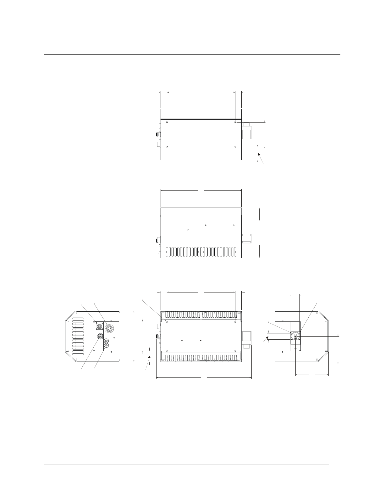
A.4 25 Watt ODPA Equipment Outline (Non L-Band)
1.66 [42.16]
4X 1/4-20 X .375 DP
11.75 [298.45]
15.07 [382.78]
1.66 [42.16]
4.00 [101.6]
3.68 [93.4]
9.00 [228.6]
4X 1/4-20 X .250 DP
TAPPED HOLES
AC POWER INLET
KPT 10 PIN MALE
6.00 [152.4]
11.50 [29 2.1]
"N" CONNECTOR
2X FUSE HOLDERS
2.29 [58.04]
Plane1
2.75 [69.85]
10.50 [266.7]
18.54 [47 0.92 ]
2.29 [58.04]
4X 6-32UNC 2B
1.04 [26.42]
1.12 [28.5]
3.12 [79.35]
WR75 WAVE GUIDE GROOVED
5.36 [136.14]
5.88 [149.25]
Figure A-3. 25Watt ODPA Equipment Outline (Non L-Band)
A–4
Page 31

Outdoor Power Amplifier Revision 0
]
W
"
Equipment Outline Drawings MN/ODPA.OM
A.5 32/40 Watt ODPA Equipment Outline (Non L-Band)
.29 [7.39]
.66 [16.87]
1.33 [33.73]
1.91 [48.49]
.29 [7.29]
6X 1/4-20 X .375 DP
.51 [12.85]
.47 [11.81]
KPT 10 PIN MALE
N" CONNECTOR
1.14 [28.91]
AC POWER INLET
4X 6-32UNC 2B
1.45 [36.93]
2X FUSE HOLDERS
2.54 [64.41]
.13 [3.35]
Figure A-4. 32/40 Watt ODPA Equipment Outline (Non L-Band)
.14 [3.61]
R75 WAVE GUIDE GROOVED
.40 [10.03]
.68 [17.22
.74 [18.87]
A–5
Page 32

Outdoor Power Amplifier Revision 0
Equipment Outline Drawings MN/ODPA.OM
A.6 25 through 40 Watt ODPA Equipment Outline (L-Band)
A
B
C
E
F
G
4
H
D
2
1
5
67
Designator Remarks Designator Remarks Designator Remarks
A 11.20 K 3.75 1 WR75 Waveguide Grooved
B 12.51 L 21.25 2 4x 6-32 UNC 2B
C 15.10 M 6.15 3 6x 1/4-20 x .250 DP
D 2.30 N 8.07 4 2x Fuse Holders
E 10.50 P 4.44 5 AC IN
F 5.25 6 KPT 10 Pin Male
G 2.30 7 “N” RF IN
H 4.00
J 1.50
J
K
Note: All dimensions are in English units.
Figure A-5. 25-40 Watt ODPA Equipment Outline (L-Band)
3
L
M
NP
A–6
Page 33

METRIC CONVERSIONS
Units of Length
Unit
1 centimeter — 0.3937 0.03281 0.01094
1 inch 2.540 — 0.08333 0.2778
1 foot 30.480 12.0 — 0.3333
1 yard 91.44 36.0 3.0 —
Centimeter
Inch
Foot
Yard
Mile
6.214 x 10
1.578 x 10
1.893 x 10
5.679 x 10
Meter
-6
-5
-4
-4
0.01 — —
0.254 — 25.4
0.3048 — —
0.9144 — —
Kilometer Millimeter
1 meter 100.0 39.37 3.281 1.094
1 mile
1 mm — 0.03937 — — — — — —
1 kilometer — — — — 0.621 — — —
1.609 x 10
5
6.336 x 10⁴ 5.280 x 10³ 1.760 x 10³
6.214 x 10
-4
—
— — —
1.609 x 10³
1.609 —
Temperature Conversions
Unit
32° Fahrenheit
212° Fahrenheit
-459.6° Fahrenheit
° Fahrenheit
—
—
—
° Centigrade
0
(water freezes)
100
(water boils)
273.1
(absolute 0)
Formulas
C = (F - 32) * 0.555
F = (C * 1.8) + 32
Units of Weight
Unit
1 gram — 0.03527 0.03215 0.002205 0.002679 0.001
Gram
Ounce
Avoirdupois
Ounce
Troy
Pound
Avoir.
Pound
Troy
Kilogram
1 oz. avoir. 28.35 — 0.9115 0.0625 0.07595 0.02835
1 oz. troy 31.10 1.097 — 0.06857 0.08333 0.03110
1 lb. avoir. 453.6 16.0 14.58 — 1.215 0.4536
1 lb. Troy 373.2 13.17 12.0 0.8229 — 0.3732
1 kilogram
1.0 x 10
3
35.27 32.15 2.205 2.679 —
Page 34

2114 WEST 7TH STREET TEMPE ARIZONA 85281 USA
480 • 333 • 2200 PHONE
480 • 333 • 2161
FAX
 Loading...