

Page 1

D
p
HPO
C, X, Ku High-Powered Outdoor Amplifier
Installation and O
eration Manual
Part Number MN/HPOD.IOM
Revision 2
Page 2

Page 3

Comtech EF Data is an ISO 9001
Registered Company
HPOD
C, X, Ku High-Powered Outdoor Amplifier
Installation and Operation Manual
Part Number MN/HPOD.IOM
REVISION 2
5/15/2007
Page 4

HPOD Revision 2
Preface MN/HPOD.IOM
iv
Page 5

HPOD Revision 2
Preface MN/HPOD.IOM
CUSTOMER SUPPORT
Contact the Comtech EF Data Customer Support Department for:
• Product support or training
• Reporting comments or suggestions concerning manuals
• Information on upgrading or returning a product
A Customer Support representative may be reached at:
Comtech EF Data
Attention: Customer Support Department
2114 West 7th Street
Tempe, Arizona 85281 USA
480.333.2200 (Main Comtech EF Data Number)
480.333.4357 (Customer Support Desk)
480.333.2161 FAX
To return a Comtech EF Data product (in-warranty and out-of-warranty) for repair or replacement:
• Contact the Comtech EF Data Customer Support Department. Be prepared to supply the
Customer Support representative with the model number, serial number, and a description of
the problem.
• Request a Return Material Authorization (RMA) number from the Comtech EF Data
Customer Support representative.
• Pack the product in its original shipping carton/packaging to ensure that the product is not
damaged during shipping.
• Ship the product back to Comtech EF Data. (Shipping charges should be prepaid.)
For Online Customer Support:
An RMA number request can be requested electronically by contacting the Customer Support
Department through the online support page at
Click on the “RMA Request Form” hyperlink, then fill out the form completely before sending.
Click on “Return Material Authorization” for detailed instructions on our return procedures.
www.comtechefdata.com/support.asp.
Send e-mail to the Customer Support Department at
For information regarding this product’s warranty policy, refer to page
service@comtechefdata.com.
xi.
v
Page 6

HPOD Revision 2
Preface MN/HPOD.IOM
Table of Contents
CHAPTER 1. INTRODUCTION................................................................................ 1–1
1.1 Introduction.......................................................................................................................................................1–1
1.2 Field Replaceable Power Supply......................................................................................................................1–2
1.3 The Solid-State Advantage................................................................................................................................1–2
1.4 Functional Description......................................................................................................................................1–2
1.5 Built-In Redundancy Controller......................................................................................................................1–2
1.6 Option Free........................................................................................................................................................1–3
1.7 Phase Combining...............................................................................................................................................1–3
1.8 Optional “Smart BUC” Functionality .............................................................................................................1–3
1.9 Featured Packed................................................................................................................................................1–3
1.10 Specifications....................................................................................................................................................1–4
CHAPTER 2. SYSTEM OPERATION...................................................................... 2–1
2.1 Interface Connectors.........................................................................................................................................2–1
2.2 Turning On the SSPA........................................................................................................................................2–6
CHAPTER 3. THEORY OF OPERATION................................................................3–1
3.1 SSPA Block Diagram.........................................................................................................................................3–1
3.2 SSPA Module.....................................................................................................................................................3–3
3.3 Cooling System...................................................................................................................................................3–3
3.4 Monitor and Control (M&C)............................................................................................................................3–3
3.5 Power Supply.....................................................................................................................................................3–4
3.6 Block Up Converter Input Option...................................................................................................................3–4
vi
Page 7

HPOD Revision 2
Preface MN/HPOD.IOM
CHAPTER 4. CUSTOMER COMMANDS ................................................................4–1
4.1 Introduction.......................................................................................................................................................4–1
4.2 RF Input Level...................................................................................................................................................4–1
4.3 Attenuator Control............................................................................................................................................4–1
4.4 Mute Control......................................................................................................................................................4–1
4.5 Faults ..................................................................................................................................................................4–2
4.6 Power Detector...................................................................................................................................................4–2
4.7 Some Common Commands...............................................................................................................................4–3
4.8 Remote Control Protocol and Structure..........................................................................................................4–3
4.9 RS-485.................................................................................................................................................................4–3
4.10 RS-485 (full duplex) summary:......................................................................................................................4–4
4.11 RS-232...............................................................................................................................................................4–4
4.12 Basic Protocol...................................................................................................................................................4–4
4.13 Packet Structure..............................................................................................................................................4–5
4.7 Remote Commands............................................................................................................................................4–8
CHAPTER 5. MAINTENANCE ................................................................................. 5–1
5.1 Power Supply Removal.....................................................................................................................................5–1
5.2 Fan Removal......................................................................................................................................................5–3
5.3 Scheduled Maintenance.....................................................................................................................................5–5
5.4 Dimensional Envelope.......................................................................................................................................5–5
APPENDIX A. ASSEMBLY KITS.............................................................................A–1
A.1 Redundant Switch Kits....................................................................................................................................A–1
APPENDIX B REDUNDANCY.................................................................................B–1
B.1 Redundancy Operation....................................................................................................................................B–1
B.2 1:1 Mode ...........................................................................................................................................................B–1
vii
Page 8

HPOD Revision 2
Preface MN/HPOD.IOM
B.3 1:2 Mode ...........................................................................................................................................................B–2
APPENDIX C. 1:1 HPOD SERIES REDUNDANCY TEST.......................................C–1
C.1 Connection........................................................................................................................................................C–1
C.2 Operation..........................................................................................................................................................C–2
viii
Page 9
HPOD Revision 2
Preface MN/HPOD.IOM
ABOUT THIS MANUAL
This manual provides installation and operation information for the Comtech EF Data
HPOD. This is a technical document intended for earth station engineers, technicians,
and operators responsible for the operation and maintenance of the HPOD.
CONVENTIONS AND REFERENCES
C
AUTIONS AND WARNINGS
CAUTION indicates a hazardous situation that, if not avoided, may
result in minor or moderate injury. CAUTION may also be used to
CAUTION
indicate other unsafe practices or risks of property damage.
WARNING indicates a potentially hazardous situation that, if not
avoided, could result in death or serious injury.
WARNING
IMPORTANT indicates a statement that is associated with the task
IMPORTANT
being performed.
METRIC CONVERSION
Metric conversion information is located on the inside back cover of this manual. This
information is provided to assist the operator in cross-referencing English to Metric conversions.
TRADEMARKS
Other product names mentioned in this manual may be trademarks or registered trademarks of
their respective companies and are hereby acknowledged.
REPORTING COMMENTS OR SUGGESTIONS CONCERNING THIS
MANUAL
Comments and suggestions regarding the content and design of this manual will be appreciated.
To submit comments, please contact:
Comtech EF Data Technical Publications Department: techpub@comtechefdata.com
SAFETY NOTICE
This equipment has been designed to minimize exposure of personnel to hazards.
ix
Page 10

HPOD Revision 2
Preface MN/HPOD.IOM
The operators and technicians must:
• Know how to work around, with and on high voltage equipment.
• Exercise every precaution to ensure personnel safety.
• Exercise extreme care when working near high voltages.
• Be familiar with the warnings presented in this manual.
CAUTION
A Neutral Fusing - Double pole/ neutral fusing used on the prime
power supply input.
INSTALLATION GUIDELINES REGARDING POWER LINE QUALITY
Comtech EF Data has become familiar with the varying quality of the
AC power grid around the world. The following offers some
IMPORTANT
• Surge suppression: High voltage surges can cause failure of the power supply. These
surges are typically caused by circuit switching on the main AC power grid, erratic
generator operation, and also by lightning strikes. While the HPOD does have built in
surge suppression, if the unit will be installed in a location with questionable power grid
quality, Comtech EF Data recommends installation of additional power
conditioning/surge suppression at the power junction box.
• Grounding: The HPOD provides a grounding terminal. This is provided to allow the
user to ground the HPOD to the antenna’s grounding network. All components installed
at the antenna should be grounded to a common grounding point at the antenna.
• Electrical welding: If welding needs to take place at the antenna, disconnect all cables
from the HPOD except for the ground wire. Cap all RF connections with terminations.
This will prevent damage to the input/output circuitry of the HPOD.
• Lightning: Lightning strikes on or around the antenna will generate extremely high
voltages on all cables connected to the HPOD. Depending on the severity of the strike,
the HPOD’s internal surge protection combined with the recommended external
suppression may protect the HPOD’s power supply. However, if the installation will be
in an area with a high probability of lightning strikes, Comtech EF Data recommends the
installation of surge suppression on the RF and IF cables. One source of these
suppressors is PolyPhaser (www.polyphaser.com)
For further information, contact Comtech EF Data, Customer Support Department.
installation guidelines that should help ensure a reliable installation.
x
Page 11

HPOD Revision 2
Preface MN/HPOD.IOM
WARRANTY POLICY
Comtech EF Data products are warranted against defects in material and workmanship for a
period of two years from the date of shipment. During the warranty period, Comtech EF Data
will, at its option, repair or replace products that prove to be defective.
For equipment under warranty, the owner is responsible for freight to Comtech EF Data and all
related customs, taxes, tariffs, insurance, etc. Comtech EF Data is responsible for the freight
charges only for return of the equipment from the factory to the owner. Comtech EF Data will
return the equipment by the same method (i.e., Air, Express, Surface) as the equipment was sent
to Comtech EF Data.
All equipment returned for warranty repair must have a valid RMA number issued prior to return
and be marked clearly on the return packaging. Comtech EF Data strongly recommends all
equipment be returned in its original packaging.
Comtech EF Data Corporation’s obligations under this warranty are limited to repair or
replacement of failed parts, and the return shipment to the buyer of the repaired or replaced parts.
Limitations of Warranty
The warranty does not apply to any part of a product that has been installed, altered, repaired, or
misused in any way that, in the opinion of Comtech EF Data Corporation, would affect the
reliability or detracts from the performance of any part of the product, or is damaged as the result
of use in a way or with equipment that had not been previously approved by Comtech EF Data
Corporation.
The warranty does not apply to any product or parts thereof where the serial number or the serial
number of any of its parts has been altered, defaced, or removed.
The warranty does not cover damage or loss incurred in transportation of the product.
The warranty does not cover replacement or repair necessitated by loss or damage from any
cause beyond the control of Comtech EF Data Corporation, such as lightning or other natural and
weather related events or wartime environments.
The warranty does not cover any labor involved in the removal and or reinstallation of warranted
equipment or parts on site, or any labor required to diagnose the necessity for repair or
replacement.
xi
Page 12

HPOD Revision 2
Preface MN/HPOD.IOM
The warranty excludes any responsibility by Comtech EF Data Corporation for incidental or
consequential damages arising from the use of the equipment or products, or for any inability to
use them either separate from or in combination with any other equipment or products.
A fixed charge established for each product will be imposed for all equipment returned for
warranty repair where Comtech EF Data Corporation cannot identify the cause of the reported
failure.
Exclusive Remedies
Comtech EF Data Corporation’s warranty, as stated is in lieu of all other warranties, expressed,
implied, or statutory, including those of merchantability and fitness for a particular purpose. The
buyer shall pass on to any purchaser, lessee, or other user of Comtech EF Data Corporation’s
products, the aforementioned warranty, and shall indemnify and hold harmless Comtech EF Data
Corporation from any claims or liability of such purchaser, lessee, or user based upon allegations
that the buyer, its agents, or employees have made additional warranties or representations as to
product preference or use.
The remedies provided herein are the buyer’s sole and exclusive remedies. Comtech EF Data
shall not be liable for any direct, indirect, special, incidental, or consequential damages, whether
based on contract, tort, or any other legal theory.
xii
Page 13
1.1 INTRODUCTION
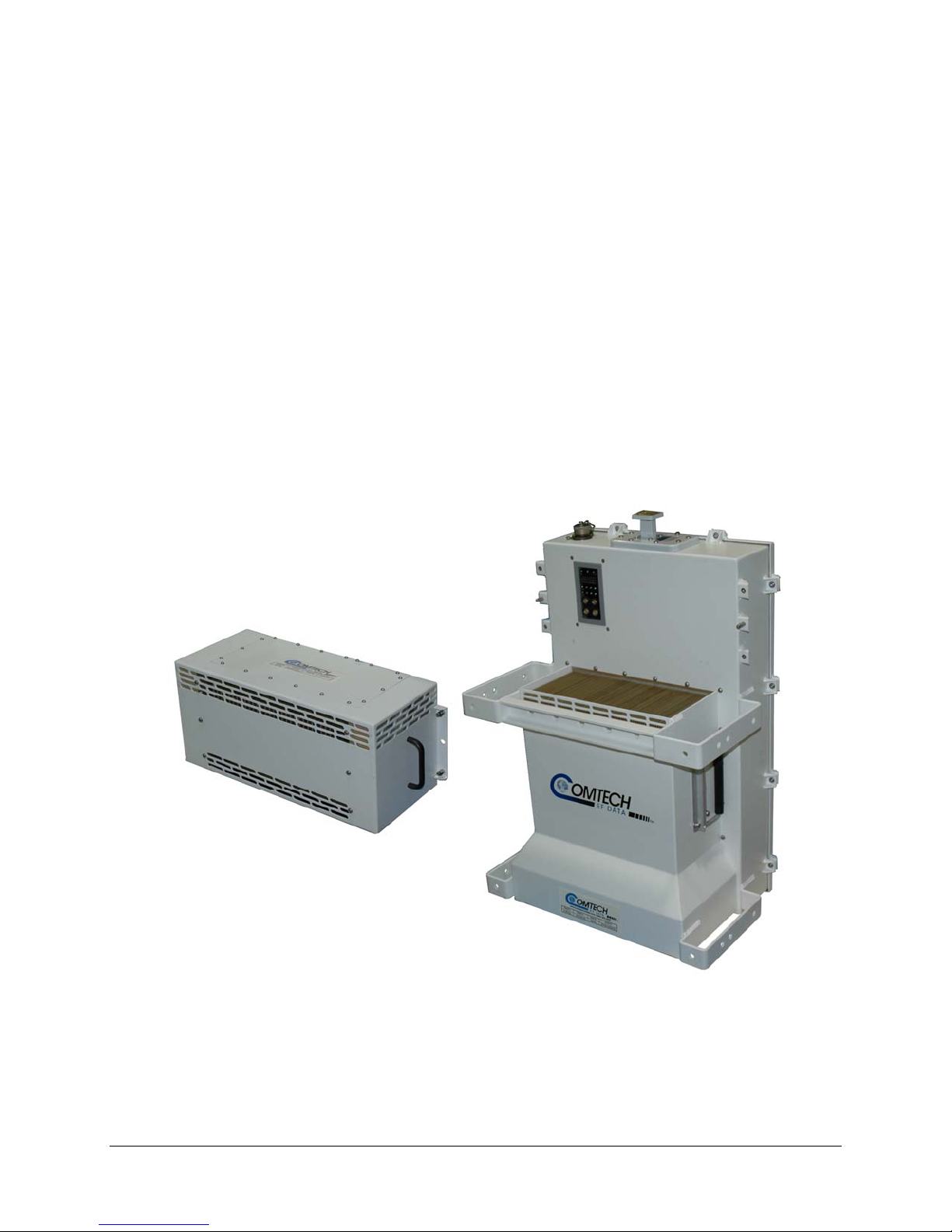
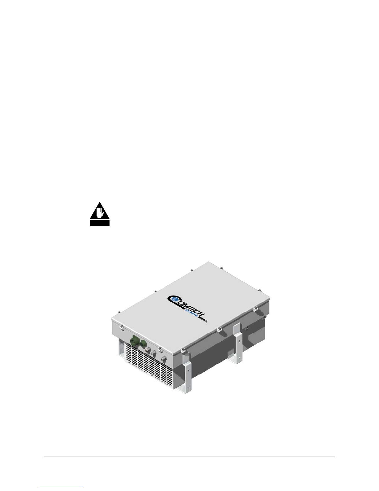
The High-Power Outdoor (HPOD) Solid-State Power Amplifier (SSPA) shown in Figure
1-1 delivers its rated power, guaranteed, at the 1 dB compression point, to the transmit
waveguide flange. It provides a cost effective, more reliable replacement for TWT
amplifiers in satellite communications.
Chapter 1. INTRODUCTION
Figure 1-1. HPOD SSPA
1–1
Page 14

HPOD Revision 2
Introduction
1.2 FIELD REPLACEABLE POWER SUPPLY
Recognizing that the MTBF limiting factor for almost all electronic equipment is the
power supply, the HPOD provides for easy field replacement. Simply disconnect the AC
mains, release the captive fasteners, and remove the supply from the SSPA module.
1.3 THE SOLID-STATE ADVANTAGE
Each HPOD SSPA is constructed with highly reliable GaAs FETs. With third order
intermodulation products from 4 to 6 dB better than TWT ratings, the CEFD unit replaces
TWTs with saturated power levels of up to twice the HPOD’s rated output. The HPOD
SSPAs also provide an MTBF that is 4 to 5 times greater than the typical TWT MTBF.
1.4 FUNCTIONAL DESCRIPTION
Each HPOD consists of a CEFD SSPA module with the Monitor/Control Processor
(MCP), a field replaceable power supply, and a field replaceable fan assembly. The
amplifier features a Comtech EF Data low loss combining technique and MCP based
temperature versus gain compensation.
1.5 BUILT-IN REDUNDANCY CONTROLLER
Each Comtech EF Data HPOD has the ability to function as a 1+1 (one backup for one
primary) and 1+2 (one backup for two primary) redundant controller in the backup mode.
The optional redundancy configuration is implemented by attaching a ganged
waveguide/coax transfer switch(es) to the input and output connectors of the amplifiers
with a combination coaxial cable and waveguide kit. When the backup SSPA is
commanded into the controller mode, it monitors the online SSPA(s) for faults. A faulted
online unit may be disconnected and replaced without affecting the online power
amplifier.
1–2
Page 15

HPOD Revision 2
Introduction
1.6 OPTION FREE
Comtech EF Data’s HPOD series of SSPAs come equipped with useful features that
other manufacturers offer as options. Included in the base price are temperature
compensation, sample ports, power monitor, field replaceable power factor corrected
supply, and full remote monitor and control capabilities.
Higher power is available through the use of CEFD 1:1 and 1:2 phase combining kits.
1.7 PHASE COMBINING
Comtech EF Data’s phase-combined systems allow the outputs of two amplifiers to be
summed together. A “normal” 1:1 system using 300W amplifiers provides 300W of
output power (the offline unit’s capabilities are unusable). The same amplifiers in a 1:1
phase-combined system will provide 600W of output power in normal operation, and a
“soft failure” state of 300W. If no degradation on failure can be accommodated, a third
amplifier can be added to form a 1:2 phase-combined system.
1.8 OPTIONAL “SMART BUC” FUNCTIONALITY
Comtech EF Data’s unique approach to L-Band/RF frequency conversions eliminates DC
and 10 MHz from the input coax. This simplifies redundant and multi-carrier operation.
It offers full 13.75 to 14.5 GHz Ku coverage and supports industry standard FSK
modem/BUC communications. The optional BUC can lock to an external or internal
reference oscillator.
1.9 FEATURED PACKED
Comtech EF Data’s HPOD SSPAs come equipped with useful features such as:
temperature compensation, sample ports, power monitor, field-replaceable power factor
corrected supply, and full remote monitor and control capabilities.
1–3
Page 16

HPOD Revision 2
Introduction
1.10 SPECIFICATIONS
SPECIFICATIONS
Output
Frequency C-Band
Available Power: Outputs
P1dB (Psat), Watts
(See Note)
Phase Combined Systems
P1dB (Psat ), Watts
(See Note)
Mute -60 dBc
Impedance 50Ω
VSWR 1.25:1 Maximum
Connector C-Band
5.850 to
6.425 GHz
C-Band
200(250)
250(300)
350(400)
400(500)
500(600)
700(800)
CPR-137G
Waveguide
Gain
Linear C- and X-Band
Adjust 20 dB in 0,25 dB steps
Full Band
with BUC option
Per 40 MHz
with BUC option
-40 to +55°C
with BUC option
70 dB min, 75 dB
typical
± 1.0 dB
± 1.5 dB
± 0.25 dB
± 0.30 dB
± 1.0 dB
± 1.5 dB
Third Order Intermodulation
Products -30 dBc typical, -25 dBc max @
3 dB total back-off from rated P1dB
(two tones, ∆f = 1 MHz)
AM to PM Conversion
2° typical, 3.5° maximum at rated output
Group Delay (per 40 MHz)
Linear ± 0.03 ns/MHz
Parabolic ± 0.003 ns/MHz
Ripple ± 1.0 ns peak to peak
X-Band
7.9 to
8.4 GHz
X-Band
175(200)
200(250)
282(350)
350(400)
400(500)
550(700)
X-Band
CPR-112G
Waveguide
2
Ku-Band
14.0 to
14.5 GHz
13.75 to
14.5 GHz
(Optional)
KU-Band
80(100)
100(125)
160(200)
200(250)
Ku-Band
WR75G
Waveguide
Ku-Band
65 dB min, 70 dB
typical
Spurious
Second Harmonic C- and X-Band
-60 dB dBc max @ 1 dB below rated
Optional BUC
LO Leakage -20 dBm
Note: P1dB over all temp/frequencies, Psat typ.
output
Input
Impedance 50Ω
Noise Figure
with BUC option
VSWR
with BUC option
Connector Type N
8 dB typical, 10 dB maximum @ maximum
gain (15 dB for HPOD Ku-Band)
25 dB
1.25:1 Maximum
1.50:1 Maximum
Sample Ports
Output Sample Type N, 50Ω, -40 dBc nominal
Input Sample Type N, 50Ω, -20 dBc nominal
Remote Control
Com Port RS-485 or RS-232
Alarms
Summary Fault Form C
Environmental
Operating Temp. -40° to +55°C (-40° to 131°F)
Non-Operating Temp. -50° to +75°C (-58° to 167°F)
Operating Humidity 0 to 100% condensing
Altitude 10,000 ft above sea level (derated 2°C/ 1000
ft AMSL)
Power Requirements
C- and X-Band
180 to 264 VAC,
47 to 63 Hz
Physical
Dimensions 26.77L x 17.88W x 11.49H inches
Weight 75 lbs (34 kg) nominal
(67.99L x 45.41W x 29.18H cm)
Available Options
Optional BUC
Ku-Band
180 to 264 VAC,
47 to 63 Hz
1–4
Page 17
Chapter 2. SYSTEM OPERATION
This section contains instructions for operating the HPOD outdoor SSPA. The primary
customer interface to the HPOD is via the Remote Communications port. This section
defines in detail the customer interface.
2.1 INTERFACE CONNECTORS
2.1.1 CONNECTOR J1: RF IN
The RF Input connector is a type N female. Typical input levels (-30 dBm) depend on
desired output power and unit attenuation. To prevent damage to the SSPA, RF input
levels should not exceed +15 dBm.
Figure 2-1. Interface Connectors
2–1
Page 18
HPOD Revision 2
System Operation
2.1.2 CONNECTOR J2: RF OUT
The RF Output connector is a waveguide interface. The flange is described below
according to the frequency range of the unit.
Table 2-1. Waveguide Output Flange
Unit Frequency Band Waveguide Flange
C CPR112G
X CPR137G
Ku WR75G
For safety reasons, never look directly into the waveguide output..
WARNING
2.1.3 CONNECTOR J10: OPTIONAL -48V DC POWER SUPPLY
Before applying DC power to the unit, make sure the waveguide output of the
amplifier is properly loaded or terminated. Failure to do so could lead to
WARNING
The power connection for the optional –48V DC supply is located on the power supply
itself. A cap (CEFD PN HW/CAP-5015) is provided with the supply that must be
installed on the AC Power Connector(J3) located on the amplifier.
The prime power input requirements are
• -36 to -72 VDC
• Careful consideration must be given to the choice of input wiring
equipment damage and excessive RF radiation levels.
because of the current draw requirements of the HPOD. Wire that is 8
AWG or larger will be required for most installations.
• The total power required from the prime power supply depends on the
model used. Please refer to the respective data sheets.
2–2
Page 19

HPOD Revision 2
System Operation
The DC prime power input connector, J10, is a 4-pin circular connector. A mating
connector (CA3106E2222SB, CEFD PN CN/CA3106E2222SB) is provided. The pin-out
specifications for J10 and its mate are contained in the table below.
Table 2-2. Connector J10 Pinout
Pin Description
A V+
B No Connect
C No Connect
D VMating connector: CA3106E2222SB, CEFD PN CN/CA3106E2222SB
2.1.4 CONNECTOR J3: AC POWER MAINS
Before applying AC power to the unit, make sure the waveguide output of the
amplifier is properly loaded or terminated. Failure to do so could lead to
WARNING
The prime power input requirements are
equipment damage and excessive RF radiation levels.
• 180-264 VAC
• 47 to 63 Hz
• The power supply is power factor corrected. The total power required
from the prime power supply depends on the model used. Please refer
to the respective data sheets.
The AC prime power input connector, J3, is a 3 pin circular connector, type CA3102E2019PB FMLB A. The ground pin A, is of the first make, last break type. A mating
connector (CA3106E20-19SB) is provided. The pin-out specifications for J3 and it’s
mate are contained in the table below.
Table 2-3. Connector J3 Pinout
Pin Description
A Ground
B L2
C L1
2–3
Page 20

HPOD Revision 2
System Operation
2.1.5 CONNECTOR J4: REDUNDANT LOOP
The Redundant Loop Connector J4 is located near the waveguide output and is only
utilized in configurations where the SSPA controls waveguide switching. In alternate
configurations, such as “chain switching”, another system block or external M&C
controls the waveguide switching. In this case, the connector remains unused and the
protective cap should be left attached. The pin-out specification is shown in
Table 2-4. Connector J4 Pinout
Pin Name
A SW_CMD_A1
B SW_CMD_COM
C SW_CMD_A2
D SW_IND_A1
E SW_IND_A2
F SW_CMD_B1
G SW_CMD_B2
H SW_IND_B1
J SW_IND_B2
K ADDR_1
L ADDR_2
M COM
N RED_1_1
P RED_1_2
R SMFLT_1_IN
S SMFLT_2_IN
T SMFLT_OUT
U RED_TXD
V RED_RXD
Table 2-4.
2–4
Page 21

HPOD Revision 2
System Operation
2.1.6 CONNECTOR J6: COM 1, REMOTE COMMUNICATIONS AND DISCRETE
CONTROL PORT
The COM 1/ Discrete Control connector J6 is the primary input for controlling and
monitoring the SSPA. It is a 19-pin circular connector, type MS3112E14-19S. The pinout specification is contained in Table 2-5.
Mating connector: ITT: KPT06J14-19P or MS3116J14-19P.
Pin Name Description
A RS485_+RX
B RS485_-RX
C RS485_+TX
D RS485_-TX
E RS232_RD
F Analog_P wr_Mon Reserved for future use
G RS232_TD
H Aux_In
J Aux_Out Not for customer use
K SumFLT_COM
L SumFLT_NO Open when faulted, else tied to Pin K.
M SumFLT_NC When faulted, tied to Pin K, else open.
N GND
P ONLINE_Status Not for customer use
R +24V Not for customer use
S Mute Control SSPA will be muted if this pin is grounded
T Minor_FLT_COM Reserved for future use
U Minor_FLT_NO Reserved for future use
V Minor_FLT_NC Reserved for future use
.
Table 2-5. Connector J6 Pinout
Auxiliary fault input, software enabled. When enabled, pin must be grounded
to unmute SSPA
2.1.7 CONNECTOR J8: INPUT SAMPLE
The Input sample port connector is a type N female. It provides a nominal –20 dB
sample of the input signal. A calibration label is provided near the connector that shows
the actual coupling values vs. frequency.
2–5
Page 22
HPOD Revision 2
System Operation
2.1.8 CONNECTOR J9: OUTPUT SAMPLE
The Output sample port connector is a type N female. It provides a nominal -40 dB
sample of the output signal. A calibration label is provided near the connector that shows
the actual coupling values vs. frequency.
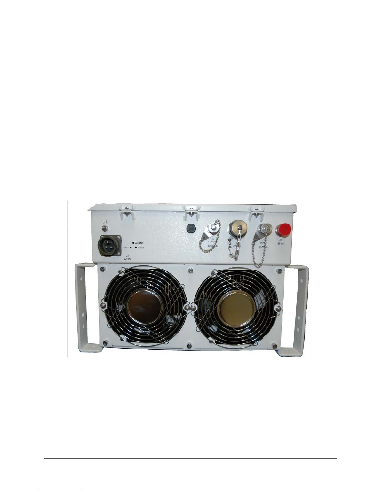
2.2 TURNING ON THE SSPA
The SSPA does not contain a ‘Power On/Off’ switch. The SSPA is powered ON by
connecting the J3 AC Power connector to the appropriate prime power source. The Mute
or Transmit status of the SSPA will automatically come up in the last stored state (factory
default = Transmit on, not muted).
Never turn the unit ON without proper waveguide termination on the
J2 “RF OUTPUT” port. Individuals can be exposed to dangerously
WARNING
high electromagnetic levels.
Figure 2-2. Outdoor Unit
2–6
Page 23

Chapter 3. THEORY OF OPERATION
This section provides an overview of the Theory of Operation of the unit. Included are a
basic block diagram and an explanation of the functions of each of the major systems.
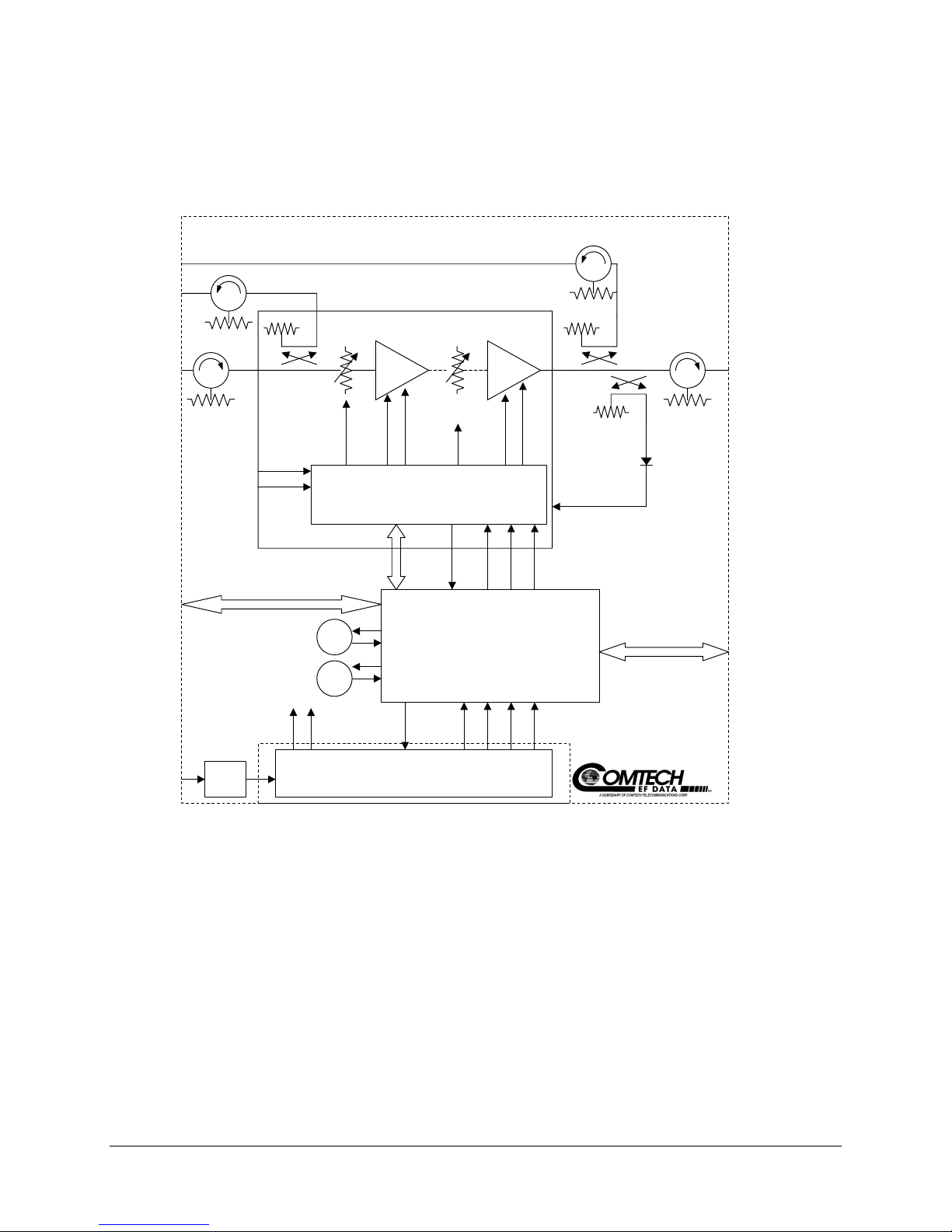
3.1 SSPA BLOCK DIAGRAM
A block diagram of the SSPA is shown on the following page in Figure 3-1. The major
components of the unit are:
• SSPA Module
• Cooling System
• Monitor and Control (M&C)
• Power Supply (Power Factor Corrected and Removable/Field Replaceable)
3–1
Page 24
HPOD Revision 2
Theory of Operation MN/HPOD.IOM
OUTPUT
SAMPLE
INPUT
SAMPLE
RF INPUT
COM/
DISCRETE
CONTROL
BLOCK DIAGRAM
J9
J8
SSPA MODULE
RF
J1
10V A
10V B
CUST.GAIN
CTRL
-5V -5V10V 10V
TEMP
COMP
OUTPUT
POWER
DETECTOR
POWER CONDI TIONING & CONTR OL
CONTROL
& MONITOR
-5V
Interlock
+5.8V
-5.8V 15V
J6
FAN1
MONITOR & CONTROL
FAN2
J2
OUTPUT
(W/G)
REDUNDANT
J4
LOOP
AC IN
10V A
Line
J3
Filter
10V B
-5V
Interlock
POWER SUPPLY
(FIELD REMOVABLE/
REPLACEABLE)
+5.8V 15V-5.8V24V
Figure 3-1. SSPA Block Diagram
3–2
Page 25

HPOD Revision 2
Theory of Operation MN/HPOD.IOM
3.2 SSPA Module
The amplifier module performs the core function of the unit. An isolator is at the RF
input to ensure good VSWR. The RF signal then passes through an input sample port
and on to an electronically controlled attenuator that adjusts the overall attenuation
according to the user input. After some amplification, a second attenuator is
automatically controlled via a look-up table to maintain the amplifier gain at a constant
level over temperature variations.
The RF signal is then amplified by a multi-stage design that utilizes proprietary
combining techniques to meet the rated power requirements. The output circuitry
contains a coupler to provide a sampled signal for monitoring purposes. A power
detector circuit also is included and the reading can be accessed via remote
communication. A high power circulator and load is located at the output to provide
good VSWR and protection from external mismatch.
3.3 Cooling System
The SSPA unit contains a robust heat sink and thermal design to maintain a low operating
temperature. Two temperature controlled fans, which are monitored by the M&C board,
draw cool outside air in across the power supply and specialized heat sink and exhaust
the warmer air out the bottom of the unit. The amplifier module temperature is
monitored, and if for any reason the amplifier temperature exceeds a safe preset limit, the
amplifier module supply is shut down to protect the unit from thermal failure.
3.4 Monitor and Control (M&C)
The unit includes a microprocessor based system that provides monitoring and control of
the essential parameters of the unit. The user interfaces with the unit through the M&C
system via the remote control/discrete communications port. The unit is capable of either
RS-232 or RS-485 remote communication. A discrete mute control and relay status
output is also available. The M&C system monitors the fan speed, unit temperature, all
power supply voltages, power transistor currents, output power, etc. Should a critical
monitored parameter fail, the unit will mute the RF signal and report a fault. The details
of the fault can be accessed via remote communication.
The M&C is also capable of acting as a controller in certain 1:1 or 1:2 redundant systems.
When configured as the back-up SSPA in such a system, it communicates with the other
SSPA(s) and toggles the waveguide switches as necessary.
3–3
Page 26

HPOD Revision 2
Theory of Operation MN/HPOD.IOM
3.5 POWER SUPPLY
The SSPA features a removable power supply which is also power factor corrected. It
connects to the main chassis via a specialized connector capable of the required high
current. It supplies several voltages necessary for the unit to operate. The 10V output is
capable of 2000W and supplies current to the power transistors in the RF amplifier
module via two paths, or cables (10V A and 10V B). The output status of this power
supply is controlled by circuitry within the RF module. If the RF module does not have
the –5V supply for any reason, it will not allow the 10V power supply to turn on. This
protects the power transistors within the RF module from failure due to improper power
supply sequencing. The +24V output powers the cooling fans and is the source of power
for waveguide switching when the SSPA is used in redundant configurations. The +5
and +15 voltages are used to operate the M&C board and other overhead functions.
3.6 BLOCK UP CONVERTER INPUT OPTION
The HPOD amplifier, when delivered from the factory with an internal Block Up
Converter (BUC) translates an L-Band input carrier to the desired output frequency (C-,
X-, or Ku-). LO frequencies are as follows:
BUC-4000 C, X, Ku, Ka
Band Frequency LO Frequency Inverting
C-Band 5850 to 6650 MHz 4900 MHz No
X-Band 7900 to 8400 MHz 6950 MHz No
Ku-Band-W 13.75 to 14.50 GHz 12.800 GHz No
The same Ku-Band BUC is installed independent of amplifier bandwidth. Therefore, the
“standard,” 14.0 to 14.5 GHz HPOD has an L-Band frequency range of 1200 to 1700
MHz which translates up to 14.0 to 14.5 GHz, while the “Extended,” 13.75 to 14.5 GHz
HPOD translates L-Band frequencies from 950 to 1700 MHz up to 13.75 to 14.5 GHz.
Unlike most BUCs, no DC bias voltage should be provided on the center conductor of the
L-Band coax.
In addition, the BUC version of the HPOD is available with an internal 10 MHz
reference. As, such, no 10 MHz reference is required on the center conductor of the LBand coax. If a reference is provided on the coax, the internal reference will detect and
lock to it.
3–4
Page 27

Chapter 4. CUSTOMER COMMANDS
4.1 INTRODUCTION
This section describes the operating features of the SSPA. A few key parameters and
procedures are summarized, followed by detailed instructions of remote control
communication commands.
4.2 RF INPUT LEVEL
The required RF input level to reach the full rated output power of the SSPA is
determined by the individual amplifier maximum gain and power rating. For example, if
the test data of an SSPA rated for 250W (54 dBm) indicated a gain of 75 dB, then a
signal of :
54dBm – 75 dB = -21 dBm
would approximately give the rated output power. Increasing input power beyond this
level would result in an output signal with increasingly higher levels of distortion. Of
course, if the SSPA attenuation control is utilized, a higher level input signal level can be
accommodated. The maximum input level should never exceed 15dBm, or permanent
damage to the unit may occur.
4.3 ATTENUATOR CONTROL
The SSPA gain can be attenuated over a 30 dB range by exercising the “ATT” command.
The details for the format of this command are found later in this section.
4.4 MUTE CONTROL
The amplifier may be muted via software or discrete control. Exercising the MUT=1
command will “software” mute the unit. The amplifier also may be “hardware” muted by
pulling Pin S on the Com 1 / Discrete control connector (J6) to ground (see Chapter 1).
The Mute command provides over 75 dB of RF on/off isolation.
4–1
Page 28

HPOD Revision 1
Customer Commands MN/HPOD.IOM
However, the Mute command only turns off the first few low power stages of the
amplifier, the high power stages remain on. By allowing the higher power transistors to
stay on, the amplifier remains in more thermally stable state should the mute condition be
removed. If the user desires to completely turn off the bias to the entire amplifier
(perhaps to conserve energy in a redundant system), both the MUT=1 and AMP=0
commands should be executed.
For normal transmit operation, MUT=0 and AMP=1 are required.
4.5 FAULTS
The M&C system monitors certain key functions of the SSPA for proper operation.
Should any of these parameters exceed predetermined limits, the M&C system will
declare a fault. The conditions that trigger a fault are:
• Any power supply more than ± 10% outside its nominal value
• Either fan less than 25% of maximum speed
• I2C internal bus communications fault
• Thermal Shutdown - A temperature fault is indicated if the unit is ≥ +95°C. This
creates a summary fault and will cause the unit to mute itself and switch to the
back-up unit (if in a redundant system). However, the 10V supply to the FET
transistors will remain on until the unit reaches the thermal shutdown temperature
of ≥ 100°C. For protection reasons, the unit will shut down the 10V supply to the
power transistors at temperatures ≥ 100°C.
4.6 POWER DETECTOR
A power detector is provided to monitor the output power. It has a useful range of over
20 dB, referenced to the unit’s rated P1dB point, and its value can be read by exercising
the “RMS” command. The test data supplied with each unit gives an indication of the
excellent accuracy and flatness of the power monitor over the frequency band of
operation.
4–2
Page 29

HPOD Revision 1
Customer Commands MN/HPOD.IOM
4.7 SOME COMMON COMMANDS
A few of the most common commands and queries are listed below. Full details for each
of these are listed at the end of this section.
• RMS = Retrieve Maintenance Status. Displays voltages, fan speeds, Heatsink
temperature, output power monitor reading, etc.
• RCS = Retrieve Configuration Status. Displays current attenuation, mute,
amplifier, online, etc. status.
• RAS = Retrieve Alarm Status. Displays current alarm or fault status.
4.8 REMOTE CONTROL PROTOCOL AND STRUCTURE
This section describes the protocol and message command set for remote monitor and
control of the SSPA product.
The electrical interface is either an RS-485 multi-drop bus (for the control of many
devices) or an RS-232 connection (for the control of a single device), and data is
transmitted in asynchronous serial form, using ASCII characters. Control and status
information is transmitted in packets of variable length in accordance with the structure
and protocol defined in later sections.
4.9 RS-485
For applications where multiple devices are to be monitored and controlled, a full-duplex
(4-wire) RS-485 is preferred. Half-duplex (2-wire) RS-485 is possible, but is not
preferred.
In full-duplex RS-485 communication there are two separate, isolated, independent,
differential-mode twisted pairs, each handling serial data in different directions. It is
assumed that there is a ‘controller’ device (a PC or dumb terminal), which transmits data,
in a broadcast mode, via one of the pairs. Many ‘target’ devices are connected to this
pair, which all simultaneously receive data from the controller. The controller is the only
device with a line-driver connected to this pair; the target devices only have linereceivers connected.
In the other direction, on the other pair, each target has a tri-stateable line driver
connected, and the controller has a line-receiver connected. All the line drivers are held in
high-impedance mode until one (and only one) target transmits back to the controller.
4–3
Page 30

HPOD Revision 1
Customer Commands MN/HPOD.IOM
Each target has a unique address, and each time the controller transmits, in a framed
‘packet’ of data, the address of the intended recipient target is included. All of the targets
receive the packet, but only one (the intended) will reply. The target enables its output
line driver, and transmits its return data packet back to the controller in the other direction
on the physically separate pair.
4.10 RS-485 (FULL DUPLEX) SUMMARY:
Two differential pairs
Controller-to-target pair
Target-to-controller pair has one line receiver (controller), and all targets have tri-state
4.11 RS-232
This is a much simpler configuration in which the controller device is connected directly
to the target via a two-wire-plus-ground connection. Controller-to-target data is carried,
via RS-232 electrical levels on one conductor, and target-to-controller data is carried in
the other direction on the other conductor.
4.12 BASIC PROTOCOL
Whether in RS-232 or RS-485 mode, all data is transmitted as asynchronous serial
characters, suitable for transmission and reception by a UART. The asynchronous
character format is fixed at 8N1 (8 data bits, No parity, and 1 stop bit). Only two baud
rates are supported: 9600 baud and 19200 baud.
All data is transmitted in framed packets. The host controller is assumed to be a PC or
ASCII dumb terminal, which is in charge of the process of monitor and control. The
controller is the only device that is permitted to initiate, at will, the transmission of data.
Targets are only permitted to transmit when they have been specifically instructed to do
so by the controller.
one pair for controller to target, one pair for target to controller.
has one line driver (controller), and all targets have line-receivers.
drivers.
All bytes within a packet are printable ASCII characters, less than ASCII code 127. In
this context, the Carriage Return and Line Feed characters are considered printable.
All messages from controller to target require a response (with one exception). This will
be either to return data that has been requested by the controller, or to acknowledge
reception of an instruction to change the configuration of the target. The exception to this
is when the controller broadcasts a message (such as Set time/date) using Address 0,
when the target is set to RS-485 mode.
4–4
Page 31

HPOD Revision 1
Customer Commands MN/HPOD.IOM
4.13 PACKET STRUCTURE
Controller-to-target:
Start of Packet Target
Address
<
ASCII code 60
(1 character)
(4 characters)
Example: <0412/MUT=1{CR}
Target-to-controller:
Start of Packet Target
Address
>
ASCII
code 62
(1 character)
(4 characters)
Example: >0412/MUT=1{CR}{LF}
Each of the components of the packet is now explained.
4.13.1 START OF PACKET
Controller to Target: This is the character ‘<’ (ASCII code 60)
Target to Controller: This is the character ‘>’ (ASCII code 62)
Because this is used to provide a reliable indication of the start of packet, these two
characters may not appear anywhere else within the body of the message.
Address
De-limiter
/
ASCII code 47
(1 character)
Address
De-limiter
/
ASCII
code 47
(1 character)
Instruction
Code
(3 characters)
Instruction
Code
(3 characters)
Code
Qualifier
= or ?
ASCII code
61 or 63
(1 character)
Code Qualifier Optional
=, ?, !, or *
ASCII code 61,
63, 33 or 42
(1 character)
Optional
Arguments
(n characters)
Arguments
(From 0 to n
characters)
End of Packet
Carriage
Return
ASCII code 13
(1 character)
End of Packet
Carriage Return,
Line Feed
ASCII code 13,10
(2 characters)
4.13.2 ADDRESS
Up to 9,999 devices can be uniquely addressed. In both RS-232 and RS-485 applications,
the permissible range of values is 1 to 9999. It is programmed into a target unit using the
remote control port.
The controller sends a packet with the address of a target - the destination of
the packet. When the target responds, the address used is the same
IMPORTANT
address, to indicate to the controller the source of the packet. The controller
does not have its own address.
4–5
Page 32

HPOD Revision 1
Customer Commands MN/HPOD.IOM
4.13.3 INSTRUCTION CODE
This is a three-character alphabetic sequence that identifies the subject of the message.
Wherever possible, the instruction codes have been chosen to have some significance.
This aids in the readability of the message, should it be displayed in its raw ASCII form.
Upper case and lower case alphabetic characters may be used (A-Z, and a-z).
4.13.4 INSTRUCTION CODE QUALIFIER
This is a single character that further qualifies the preceding instruction code.
Code Qualifiers obey the following rules:
1. From Controller to Target, the only permitted values are:
= (ASCII code 61)
? (ASCII code 63)
They have these meanings:
The ‘=’ code (controller to target) is used as the assignment operator, and is used to
indicate that the parameter defined by the preceding byte should be set to the value
of the argument(s) which follow it.
For example, in a message from controller to target, MUT=1 would mean ‘enable
the mute function’.
The ‘?’ code (controller to target) is used as the query operator, and is used to
indicate that the target should return the current value of the parameter defined by
the preceding byte.
For example, in a message from controller to target, MUT? denotes ‘return the
current state of the mute function’.
2. From Target to Controller, the only permitted values are:
= (ASCII code 61)
? (ASCII code 63)
! (ASCII code 33)
* (ASCII code 42)
# (ASCII code 35)
They have these meanings:
The ‘=’ code (target to controller) is used in two ways:
First, if the controller has sent a query code to a target (for example MUT?, meaning
‘is mute enabled or disabled?’), the target would respond with MUT=x, where x
represents the state in question, 1 being ‘enable’ and 0 being disable.
4–6
Page 33

HPOD Revision 1
Customer Commands MN/HPOD.IOM
Second, if the controller sends an instruction to set a parameter to a particular value,
and, providing the value sent in the argument is valid, then the target will
acknowledge the message by replying with MUT= (with no message arguments).
The ‘?’ code (target to controller) is only used as follows:
If the controller sends an instruction to set a parameter to a particular value, and, if
the value sent in the argument is not valid, then the target will acknowledge the
message by replying (for example) with MUT? (with no message arguments). This
indicates that there was an error in the message sent by the controller.
The ‘*’ code (target to controller) is only used as follows:
If the controller sends an instruction to set a parameter to a particular value, and, if
the value sent in the argument is valid, however the target is in the wrong mode (e.g.,
standby mode in redundancy configuration) that it will not permit that particular
parameter to be changed at that time, then the target will acknowledge the message by
replying (for example) with MUT* (with no message arguments).
The ‘!’ code (target to controller) is only used as follows:
If the controller sends an instruction code which the target does not recognize, then
the target will acknowledge the message by echoing the invalid instruction, followed
by the ! character with. Example: XYZ!
The ‘#’ code (target to controller) is only used as follows:
If the controller sends an instruction code which the target cannot currently perform
because of hardware resource issues, then the target will acknowledge the message by
echoing the invalid instruction, followed by the # character. This response can only
occur if the operator sends two or more ‘hardware configuration’ type commands
without allowing adequate time between commands for the hardware to be
configured. For example, if the operator issued commands to change both the
frequency and the attenuation with less than 100 milliseconds between commands,
and if this response is returned, then the command has not been accepted and the
operator must resend the command.
4.13.5 MESSAGE ARGUMENTS
Arguments are not required for all messages. Arguments are ASCII codes for the
characters 0 to 9 (ASCII 48 to 57), period (ASCII 46) and comma (ASCII 44).
4.13.6 END OF PACKET
Controller to Target: This is the ‘Carriage Return’ character (ASCII code 13)
Target to Controller: This is the two-character sequence ‘Carriage Return’, ‘Line Feed’.
(ASCII code 13, and code 10.)
Both indicate the valid termination of a packet.
4–7
Page 34

HPOD Revision 1
Customer Commands MN/HPOD.IOM
4.7 REMOTE COMMANDS
Attenuation, 4–9
Auto Fault Recovery, 4–9
Auxiliary Mute Enable, 4–9
Circuit Identification
Clear All Stored Alarms, 4–10
Concise Alarm Status, 4–11
Concise Configuration Status, 4–11
Concise Maintenance Status, 4–12
Concise RF Power FET Current Status, 4–12
Concise Utility Status, 4–13
Mute State
Online Status
Redundancy State
Reference Oscillator Tuning, 4–14
Remote Address, 4–14
Remote Baud Rate, 4–14
, 4–13
, 4–10
, 4–13
, 4–13
Retrieve Alarm Status, 4–15
Retrieve Configuration Status, 4–16
Retrieve Equipment Type, 4–16
Retrieve Firmware Number, 4–16
Retrieve Maintenance Status, 4–17
Retrieve next 5 unread Stored Alarms, 4–18
Retrieve Number of unread, 4–18
Retrieve Utility Status, 4–19
RF Power Amplifier State
RF Power FET Current status, 4–19
Serial Number
Set RTC (Real-Time-Clock) Date, 4–20
Set RTC Time, 4–20
Summary Fault Status, 4–20
Terminal Status change
, 4–20
, 4–19
, 4–21
4–8
Page 35

HPOD Revision 1
Customer Commands MN/HPOD.IOM
4–9
Parameter Type
Command
(Instruction
Code and
Qualifier)
Arguments for
Command or
Response to
Query
Description of arguments
(Note that all arguments are ASCII numeric
codes, that is, ASCII codes between 48 and 57)
Response to
Command
(Target to controller)
Query
(Instruction
Code and
qualifier)
Response to
query
(Target to
controller)
Attenuation ATT= 5 bytes,
numerical
Command or Query.
Valid attenuation level, in dB, at 0.25-dB step size
as factory default.
Example: ATT=12.25’cr’
ATT= (message ok)
ATT? (Received ok, but
invalid arguments
found)
ATT* (message ok, but
not permitted in current
mode)
ATT? ATT=xx.xx
(Same format as
command
arguments)
Auto Fault
Recovery
AFR= 1 byte,
value of 0, 1
Command or Query.
The SSPA output will automatically be muted in
the event of detected fault. If auto fault recovery is
enabled, it will cause the output to go active (unmute) if all faults are cleared. If disabled, the
output will remain muted even if all faults are
cleared.
Example: <1/AFR=1’cr’
>0001/AFR=’cr’’lf’
AFR = (message ok)
AFR? (received ok, but
invalid arguments
found)
AFR* (message ok, but
not permitted in current
mode)
AFR? AFR=x
(same format as
command
arguments)
Auxiliary Mute
Enable
AUX= 1 byte
value of 0,1
Command or Query
Enables or disables the auxiliary mute mode.
0=Disabled
1=Enabled
Example (AUX Mute Enabled): AUX=1’cr’
Note: When enabled, Pin H of the J6 COMM 1
connector must be grounded to UN-MUTE unit.
Otherwise, unit will be muted, and if a mute query
is given (MUT?) the response will be MUT=2 to
indicate a hardware controlled mute is present.
AUX= (message ok)
AUX? (received ok, but
invalid arguments
found)
AUX* (message ok, but
not permitted in current
mode)
AUX? AUX=x
(same format as
command
arguments)
Page 36

HPOD Revision 1
Customer Commands MN/HPOD.IOM
4–10
Parameter Type
Command
(Instruction
Code and
Qualifier)
Arguments for
Command or
Response to
Query
Description of arguments
(Note that all arguments are ASCII numeric
codes, that is, ASCII codes between 48 and 57)
Response to
Command
(Target to controller)
Query
(Instruction
Code and
qualifier)
Response to
query
(Target to
controller)
Circuit
Identification
CID= 24 bytes,
alpha-numeric
Command or Query
CID is a user-defined string of data that may be
used to identify or name the unit or station. The
CID is a 24-byte field of data that is entered as one
line, but it will be read back from the unit as two
12-byte lines of data.
Examples:
<1/CID= Station #001--HPOD #01--’cr’
>0001/CID=
<1/CID?’cr’
>0001/CID=’cr’
Station #001’cr’
--HPOD #01--’cr’’lf’
CID= (message ok)
CID? (received ok, but
invalid arguments
found)
CID? CID=x…x
(see description
for details of
arguments)
Clear All Stored
Alarms
CAA= None Command only
Instructs the slave to clear all Stored Events
This command takes no arguments.
Example: <1/CAA=’cr’
>0001/CAA=’cr’’lf’
CAA= (message ok)
N/A
N/A
Page 37

HPOD Revision 1
Customer Commands MN/HPOD.IOM
4–11
Parameter Type
Command
(Instruction
Code and
Qualifier)
Arguments for
Command or
Response to
Query
Description of arguments
(Note that all arguments are ASCII numeric
codes, that is, ASCII codes between 48 and 57)
Response to
Command
(Target to controller)
Query
(Instruction
Code and
qualifier)
Response to
query
(Target to
controller)
Concise Alarm
Status
N/A 25 bytes,
alpha-numeric
Query only.
Used to Query the Alarm status of the unit,
response is comma delimited.
Example: CMS=a,b,c,d,e,f,g,h,I,j,k,I,m’cr’’lf’
where: a thru k = 0 or 1, 0 = OK 1 = FT
a = +24V Power Supply
b = +15V Power Supply
c = +10V-A Power Supply
d = +10V-B Power Supply
e = +7.5V Power Supply
f = +5V Power Supply
g = -5V Power Supply
h = Fan#1 State
i = Fan#2 State
j = Heatsink Temp
k = Shutdown
l = llC Status
m=Forward Power Alarm
N/A CAS?
CAS=x….x
(see description
for details of
arguments)
Concise
Configuration
Status
N/A 24 bytes,
alpha-numeric
Query only.
Used to query the summarized version of RCS.
Example: CCS=aaaaa,b,c,d,e-e,fffff,g,‘cr’
Where:
aaaaa = attenuation in dB
b = RF power amplifier state
c = mute state, 0 = un-muted, 1 = muted
d = online status
e-e = redundancy state and mode
fffff = gain offset in dB
g = AFR
N/A CCS? CCS=x….x
(see description
for details of
arguments)
Page 38

HPOD Revision 1
Customer Commands MN/HPOD.IOM
4–12
Parameter Type
Command
(Instruction
Code and
Qualifier)
Arguments for
Command or
Response to
Query
Description of arguments
(Note that all arguments are ASCII numeric
codes, that is, ASCII codes between 48 and 57)
Response to
Command
(Target to controller)
Query
(Instruction
Code and
qualifier)
Response to
query
(Target to
controller)
Concise
Maintenance
Status
N/A 84 bytes,
alpha-numeric
Query only.
Used to Query the Maintenance status of the unit
in a concise format. The response is comma
delimited.
Example: CMS=aaa.a,bbb.b,ccc.c,ddd.d,eee.e,
fff.f,ggg.g,hhh.h,iii.i,jjj.j,kkk.k,lll.l,mmm.m,nnn.n,
’cr’’lf’
where:
aaa.a = +24V Power Supply
bbb.b = +15V Power Supply
ccc.c = +10V-1 Power Supply
ddd.d = +10V-2 Power Supply
eee.e = +7.5V Power Supply
fff.f = +5V Power Supply
ggg.g = -5V Power Supply
hhh.h = Fan #1 speed (in percent)
iii.i = Fan #2 speed (in percent)
jjj.j = Amplifier temperature in deg. C
kkk.k = Amplifier 10V1
lll.l = Amplifier 10V2
mmm.m=Forward RF output power, in dBm
Note: nnn.n will appear for Ref Voltage if
Reference Oscillator Module is installed.
N/A CMS?
CMS=x….x
(see description
for details of
arguments)
Concise RF
Power FET
Current Status
N/A variable length
depending on
the number of
FETs installed in
the amplifier
Query only
Concise version of RFS.
Example: CFS=xxx,xxx,x.x,x.x,……….,x.x,
N/A CFS? CFS=x…..x
(see description
of RFS. Note
that each
argument is
separated by a
comma)
Page 39

HPOD Revision 1
Customer Commands MN/HPOD.IOM
4–13
Parameter Type
Command
(Instruction
Code and
Qualifier)
Arguments for
Command or
Response to
Query
Description of arguments
(Note that all arguments are ASCII numeric
codes, that is, ASCII codes between 48 and 57)
Response to
Command
(Target to controller)
Query
(Instruction
Code and
qualifier)
Response to
query
(Target to
controller)
Concise Utility
Status
N/A 11 bytes,
alpha-numeric
Query only.
Used to Query the Maintenance status of the unit,
response is comma delimited.
Example: CUS=aaaa,bbbb,ccc,’cr’’lf’
where:
aaaa = Remote Unit Address
bbbb = Remote Baud Rate
N/A CUS?
CUS=x….x
(see description
for details of
arguments)
Mute State MUT= 1 byte,
value of 0,1
Command or Query.
Mute the unit, where:
0 = Disabled
1 = Enabled
2 = Unit muted due to discrete control lines. Query
response only.
Example: MUT=1’cr’
MUT= (message ok)
MUT? (received ok, but
invalid arguments
found)
MUT* (message ok, but
not permitted in current
mode)
MUT? MUT=x
(same format as
command
arguments)
Online Status ONL= 1 byte,
value of 0, 1
Command or Query.
Online status (applies only to redundancy), where:
0 = Disabled
1 = Enabled
Example: <1/ONL=1’cr’
>0001/ONL=’cr’’lf’
ONL= (message ok)
ONL? (Received ok,
but invalid arguments
found)
ONL* (message ok, but
not permitted in current
mode)
ONL? ONL=x
Redundancy
State
RED= 1 byte,
value of 0, 1, 2
Command or Query
Turns ON or OFF the redundancy state, where:
0 = Off
1 = 1:1 Redundancy
2 = 1:2 Redundancy
Example: <1/RED=1’cr’
>0001/RED=’cr’’lf’
RED= (message ok)
RED? (received ok, but
invalid arguments
found)
RED * (message ok,
but not permitted in
current mode)
RED? RED =x
Page 40

HPOD Revision 1
Customer Commands MN/HPOD.IOM
4–14
Parameter Type
Command
(Instruction
Code and
Qualifier)
Arguments for
Command or
Response to
Query
Description of arguments
(Note that all arguments are ASCII numeric
codes, that is, ASCII codes between 48 and 57)
Response to
Command
(Target to controller)
Query
(Instruction
Code and
qualifier)
Response to
query
(Target to
controller)
Reference
Oscillator Tuning
REF= 3 bytes,
numeric
Command or Query
Adjusts the reference oscillator tuning voltage by
sending a DAC value in the following format:
REF=xxx.
Where xxx is a numeric value from 0 to 255, and
the default value is set to 87.
Example: <1/REF=87’cr’
>0001/REF=
Note: This command sets the DAC value, but the
actual Reference Oscillator tuning voltage can be
monitored using the RMS command.
REF= (message ok)
REF? (received ok, but
invalid arguments
found)
REF* (message ok, but
not permitted in current
mode)
REF? REF=xxx
(same format as
command
arguments)
Remote Address SPA= 4 bytes,
numeric
Command or Query.
Set Physical Address-between 0001 to 9999.
Resolution 0001
Example: SPA=0412’cr’
SPA= (message ok)
SPA? (received ok, but
invalid arguments
found)
SPA?
SPA=xxxx
(same format as
command
arguments)
Remote Baud
Rate
SBR= 4 bytes,
alpha-numeric
Command or Query.
Set remote baud rate as follows:
9600 = 9600 baud
19K2 = 19200 baud
Example: SBR=9600’cr’
Note: When changing baud rates remotely the
response to the command will be returned using
the same baud rate as that used to send the
command.
SBR= (message ok)
SBR? (received ok, but
invalid arguments
found)
SBR?
SBR=xxxx
(same format as
command
arguments)
Page 41

HPOD Revision 1
Customer Commands MN/HPOD.IOM
4–15
Parameter Type
Command
(Instruction
Code and
Qualifier)
Arguments for
Command or
Response to
Query
Description of arguments
(Note that all arguments are ASCII numeric
codes, that is, ASCII codes between 48 and 57)
Response to
Command
(Target to controller)
Query
(Instruction
Code and
qualifier)
Response to
query
(Target to
controller)
Retrieve Alarm
Status
N/A 117 bytes,
alpha-numeric
Query only.
Used to Query the Alarm status of the unit.
Example: <1/RAS=’cr’
>0001/RAS=’cr’
P24VT=OK’cr’
P15VT=OK’cr’
P10V1=OK’cr’
P10V2=OK’cr’
P7V5T=OK’cr’
P5VLT=OK’cr’
N5VLT=OK’cr’
FAN#1=OK’cr’
FAN#2=OK’cr’
HSTMP=OK’cr’
SHTDN=OK’cr’
IICST=OK’cr’
FPOUT=OK’cr’’lf’
Note: BUC=XX, and REF=XX will appear
in the list if the BUC, and reference
oscillator are installed.
N/A RAS?
RAS=x….x
(see description
for details of
arguments)
Page 42

HPOD Revision 1
Customer Commands MN/HPOD.IOM
4–16
Parameter Type
Command
(Instruction
Code and
Qualifier)
Arguments for
Command or
Response to
Query
Description of arguments
(Note that all arguments are ASCII numeric
codes, that is, ASCII codes between 48 and 57)
Response to
Command
(Target to controller)
Query
(Instruction
Code and
qualifier)
Response to
query
(Target to
controller)
Retrieve
Configuration
Status
N/A 45 bytes,
alpha-numeric
Query only.
Used to Query the configuration status of the unit
Example: RCS=’cr’
ATT=12.75’cr’
AMP=1’cr’
MUT=1’cr’
ONL=1’cr’
RED=1-1’cr’
GOF=00.00’cr’
AFR=1’cr’’lf’
where:
ATT= attenuation in dB
AMP= RF power amplifier state, 0=OFF, 1=ON
MUT=RF mute state, 0=un-muted, 1=muted
ONL=Online status for redundancy
RED=Redundancy state and mode,
states: 0=OFF, 1=ON,
modes: 0 = auto, 1 = manual
GOF=Gain Offset in dB
AFR= auto fault recovery, 0=manual, 1=auto
N/A RCS?
RCS=x….x
(see description
for details of
arguments)
Retrieve
Equipment Type
N/A 22 bytes,
alpha-numeric
Query only.
The unit returns a string indicating the Model
Number and the version of the MnC firmware
installed in the unit.
Example: <1/RET?’cr’
>0001/RET=CPA-300 VER: 1.0.3’cr’’lf’
N/A RET?
RET=x….x
(see description
for details of
arguments)
Retrieve
Firmware
Number
N/A Query only
Returns the firmware type loaded into the unit.
Note: the RET? Query returns the MnC firmware
revision.
Example: <1/FRW?’cr’
>0001/FRW=’cr’
BULK=FW12524’cr’
MnC =FW12522’cr’
FPGA=FW10788’cr’’lf’
N/A FRW? FRW=x…x
(see description
for details of
arguments)
Page 43

HPOD Revision 1
Customer Commands MN/HPOD.IOM
4–17
Parameter Type
Command
(Instruction
Code and
Qualifier)
Arguments for
Command or
Response to
Query
Description of arguments
(Note that all arguments are ASCII numeric
codes, that is, ASCII codes between 48 and 57)
Response to
Command
(Target to controller)
Query
(Instruction
Code and
qualifier)
Response to
query
(Target to
controller)
Retrieve
Maintenance
Status
N/A 168 bytes,
alpha- numeric
Query only.
Used to Query the maintenance status of the unit
Example:<1/RMS?’cr’
>0001/RMS=’cr’
P24VT=024.1’cr’
P15VT=015.2’cr’
P10V1=010.4’cr’
P10V2=010.4’cr’
P7V5T=007.8’cr’
P5VLT=005.8’cr’
N5VLT=-05.7’cr’
FANR1=100.0’cr’
FANR2=100.0’cr’
ATEMP=+40.0’cr’
A10V1=010.2’cr’
A10V2=010.2’cr’
FWPWR=+37.6’cr’
RVPWR=02.0’cr’’If’ (optional)
*Note: REFV will appear if REF OSC module is
installed.
N/A RMS?
RMS=x….x
(see description
for details of
arguments)
Page 44

HPOD Revision 1
Customer Commands MN/HPOD.IOM
4–18
Parameter Type
Command
(Instruction
Code and
Qualifier)
Arguments for
Command or
Response to
Query
Description of arguments
(Note that all arguments are ASCII numeric
codes, that is, ASCII codes between 48 and 57)
Response to
Command
(Target to controller)
Query
(Instruction
Code and
qualifier)
Response to
query
(Target to
controller)
Retrieve next 5
unread Stored
Alarms
N/A 145 bytes,
alpha-numeric
Query only.
The unit returns the five oldest stored events in the
alarm log, and if there are no events in the log the
unit will reply with LNA*. All events that are read
from the log are also automatically removed from
the log.
Reply format:
YYYYYYYYYY ZZ mmddyy hhmmss’cr’
YYYYYYYYYY ZZ mmddyy hhmmss’cr’
YYYYYYYYYY ZZ mmddyy hhmmss’cr’
YYYYYYYYYY ZZ mmddyy hhmmss’cr’
YYYYYYYYYY ZZ mmddyy hhmmss’cr’’lf’
Where:
YYYYYYYYYY is the fault description.
ZZ is one of the event types listed below:
FT = Fault
OK = Clear
IF = Information
The rest of the string is a date / time stamp.
Example: <1/LNA?’cr’
>0001/LNA=’cr’
LOG CLR IF 175503 052307’cr’
FAN #1 FT 175504 052307’cr’
OVR TMP FT 175504 052307’cr’
FAN #1 OK 175504 052307’cr’
IIC BUS FT 175504 052307’cr’’lf’
N/A LNA? LNA=YY..ss
(see description
for details of
arguments)
Retrieve Number
of unread
Stored Alarms
N/A 2 bytes,
numeric,
00 to 99
Query only.
Returns the number of stored events, which
remain unread in the alarm log. A maximum of 99
events may be stored in the alarm log.
Example reply: <1/TNA? ’cr’
>0001/TNA=14’cr’’lf’
N/A TNA? TNA=xx
(see description
for details of
arguments)
Page 45

HPOD Revision 1
Customer Commands MN/HPOD.IOM
4–19
Parameter Type
Command
(Instruction
Code and
Qualifier)
Arguments for
Command or
Response to
Query
Description of arguments
(Note that all arguments are ASCII numeric
codes, that is, ASCII codes between 48 and 57)
Response to
Command
(Target to controller)
Query
(Instruction
Code and
qualifier)
Response to
query
(Target to
controller)
Retrieve Utility
Status
N/A 27 bytes,
alpha- numeric
Query only.
Used to Query the utility status of the unit
Example: RUS=’cr’
ADR=0001’cr’
BDR=9600’cr’
N/A RUS?
RUS=x….x
(see description
for details of
arguments)
RF Power
Amplifier State
AMP= 1 byte,
value of 0, 1
Command or Query
Turns ON or OFF the RF power amplifiers.
0 = Off
1 = On
Example: AMP=1’cr’
AMP= (message ok)
AMP? (received ok, but
invalid arguments
found)
AMP* (message ok, but
not permitted in current
mode)
AMP? AMP=x
(same format as
command
arguments)
RF Power FET
Current status
N/A variable length
depending on
the number of
FETs installed in
the amplifier
Query only
Used to display all the FET currents.
Example: <1/RFS? ’cr’
>0001/RFS=’cr’
Q01=xx’cr’
Q02=xx’cr’
Q03=xx.x’cr’
Q04=xx.x’cr’
Q05=xx.x’cr’
Q06=xx.x’cr’
Q07=xx.x’cr’
Q08=xx.x’cr’
Q09=xx.x’cr’
Q10=xx.x’cr’
Q11=xx.x’cr’
Q12=xx.x’cr’
Q13=xx.x’cr’
Q14=xx.x’cr’
Q15=xx.x’cr’
Q16=xx.x’cr’’lf’
N/A RFS? RFS=x….x
(see description
of arguments)
Page 46

HPOD Revision 1
Customer Commands MN/HPOD.IOM
4–20
Parameter Type
Command
(Instruction
Code and
Qualifier)
Arguments for
Command or
Response to
Query
Description of arguments
(Note that all arguments are ASCII numeric
codes, that is, ASCII codes between 48 and 57)
Response to
Command
(Target to controller)
Query
(Instruction
Code and
qualifier)
Response to
query
(Target to
controller)
Serial Number N/A 9 bytes,
numeric,
000000000 to
999999999
Query only.
Used to Query the unit’s 9 digit serial number in
the form of RSN=xxxxxxxxx. Where: xxxxxxxxx is
the unit’s 9-digit serial number.
Example: <1/RSN?’cr’
>0001/RSN=072282040’cr’’lf’
N/A RSN?
RSN=xxxxxxxxx
(see description
for details of
arguments)
Set RTC (Real-
Time-Clock) Date
DAT= 6 bytes,
numeric
Command or Query.
A command in the form mmddyy, where; dd = day
of the month, between 01 and 31, mm = month of
the year, between 01 and 12 and yy = year,
between 00 and 96 (2000 to 2096)
Example (date = April 24, 2003):
<1/DAT=042503’cr’
>0001/DAT=’cr’’lf’
DAT= (message ok)
DAT? (received ok, but
invalid arguments
found)
DAT* (message ok, but
not permitted in current
mode)
DAT?
DAT=xxxxxx
(same format as
command
arguments)
Set RTC Time TIM= 6 b ytes,
numeric
Command or Query.
A command in the form hhmmss, indicating the
time from midnight, where hh = hours, between 00
and 23; mm = minutes, between 00 and 59, and ss
= seconds, between 00 and 59
Example (time = 23 hours, 12 minutes and 59
seconds since midnight.):
<1/TIM=231259’cr’
>0001/TIM=’cr’’lf’
TIM = (message ok)
TIM? (received ok, but
invalid arguments
found)
TIM * (message ok, but
not permitted in current
mode)
TIM?
TIM=xxxxxx
(same format as
command
arguments)
Summary Fault
Status
N/A 1 byte,
value of 0,1
Query only.
Indicates the condition of the summary fault relay
where:
0 = Not Faulted (SumFLT_COM J6 pin K is
connected to SumFLT_NO J6 pin L, and
SumFLT_NC J6 pin M is open)
1 = Faulted (SumFLT_COM J6 pin K is connected
to SumFLT_NC J6 pin M, and SumFLT_NO J6 pin
L is open)
Example: <1/SFS?
>0001/SFS=0’cr’’lf’
N/A SFS?
SFS=x
(see description
for details of
arguments)
Page 47

HPOD Revision 1
Customer Commands MN/HPOD.IOM
4–21
Parameter Type
Command
(Instruction
Code and
Qualifier)
Arguments for
Command or
Response to
Query
Description of arguments
(Note that all arguments are ASCII numeric
codes, that is, ASCII codes between 48 and 57)
Response to
Command
(Target to controller)
Query
(Instruction
Code and
qualifier)
Response to
query
(Target to
controller)
Terminal Status
change
N/A 1 byte,
value of 0,1
Query only.
Indicates if there has been a change in the
terminal status since the last time the command
was given. A value of 0 indicates no status
change, and a value of 1 indicates there has been
a terminal status change.
Example: <1/TSC?’cr’
>0001/TSC=0’cr’’lf’
N/A TSC? TSC=x
(see description
for details of
arguments)
Page 48

HPOD Revision 1
Customer Commands MN/HPOD.IOM
4–22
Notes:
Page 49

Chapter 5. Maintenance
5.1 POWER SUPPLY REMOVAL
CEFD’s HPOD series of outdoor SSPAs features field-replaceable power supply modules.
To remove the supply:
Step Procedure
1 Disconnect power from the SSPA
2 Loosen the four captive fasteners as indicated in
3 The supply can now be pulled from the SSPA.
IMPORTANT
To install the supply:
Step Procedure
1
2
3 Inspect the gasket for damage. Replace as required
4
5 Tighten the four captive fasteners as indicated in
Note: Be certain to use an appropriate screwdriver, such as the one provided with the
SSPA, to avoid damaging the fasteners.
The SSPA/power supply interconnection is waterproof only when the supply
and SSPA are mated. When exposed, the connection is only water resistant.
Neither the SSPA nor the power supply should not be left exposed to the
elements unless mated.
Visually inspect the exposed SSPA heat sink for any debris/ blockage. Clean as
required.
Visually inspect both the SSPA and power supply connector for damage/cleanliness.
Correct/clean as required.
Place supply on SSPA, ensuring the guide pins and connection are properly aligned.
Gently press to engage the connector.
Note: Be certain to use an appropriate screwdriver, such as the one provided with the
SSPA, to avoid damaging the fasteners.
Figure 5-1.
Figure 5-1.
5–1
Page 50

HPOD Revision 2
Maintenance MN/HPOD.IOM
Loosen 4 captive screws to
replace power supply
Figure 5-1. Power Supply Replacement
5–2
Page 51

HPOD Revision 2
Maintenance MN/HPOD.IOM
5.2 FAN REMOVAL
The fans utilized by the HPOD are designed for long life even in a harsh environment. They
are still mechanical devices subject to wear and may need replacement after several years. In
dusty environments, their removal facilitates clearing the heat sink of accumulated dust.
To remove the fan assembly:
Step Procedure
1 Disconnect power from the SSPA
2 Loosen the six captive fasteners as indicated in
3
4 Remove the fan assembly far enough to gain access to the two circular fan connectors.
5 Disconnect the circular fan connectors and remove the assembly.
Note: Be certain to use an appropriate screwdriver, such as the one provided with the
SSPA, to avoid damaging the fasteners.
(6) Captive Fasteners
Figure 5-2.
(2) Circular Fan Connectors
5–3
Figure 5-2. Fan Removal
Page 52

HPOD Revision 2
Maintenance MN/HPOD.IOM
To install the fan assembly:
Step Procedure
1
2 Connect the fan assembly’s circular connectors to the SSPA
3
4 Tighten the six captive fasteners as indicated in
Visually inspect the exposed SSPA heat sink for any debris/blockage.
Clean as required
Place assembly on SSPA, ensuring proper alignment of the fasteners without any
cable /fan interference.
Figure 5-2.
Note: Be certain to use an appropriate screwdriver, such as the one provided with the
SSPA, to avoid damaging the fasteners.
Figure 5-3. Fan Installation
5–4
Page 53

HPOD Revision 2
Maintenance MN/HPOD.IOM
5.3 SCHEDULED MAINTENANCE
Once a year (or sooner depending on environmental conditions), the SSPA heat sink should
be cleaned.
To perform this maintenance:
Step Procedure
1 Disconnect power from the SSPA
2 Remove the fan assembly as previously described
3 Remove the power supply as previously described
4
5 Also using compressed air, clear the heat sink portions of the power supply.
6 Reinstall the supply and fan assembly.
Using compressed air, blow through the SSPA heat sink to remove any foreign object
accumulation that may be obstructing airflow.
5.4 DIMENSIONAL ENVELOPE
26.77
24.35.75
5–5
Figure 5-4a. Dimensional Envelope
Page 54

HPOD Revision 2
Maintenance MN/HPOD.IOM
5.49
11.4 9
4.00
%%c.375
13.38
10.97
Figure 5-4b. Dimensional Envelope
8.94 8.94
C,
POSITION
X
IDENTICAL
&
Ku-BAND
FLANGE
2.42
9.07
7.19
17.88
Figure 5-4c. Dimensional Envelope
5–6
Page 55

HPOD Revision 2
Maintenance MN/HPOD.IOM
22.75
(57.79)
10.00
(25.4
)
Ku-Band: 1.88
(4.77)
C-Band: 1.25
(3.18)
Figure 5-5. Dimensional Clearance for Redundant Units.
13.94
(35.4)
5–7
Page 56

HPOD Revision 2
Maintenance MN/HPOD.IOM
Notes:
5–8
Page 57

Appendix A. ASSEMBLY KITS
A.1 REDUNDANT SWITCH KITS
The following figures and parts lists represent the phase combiner 1:1 redundant switch kits.
• Figure A-1. Redundant 1:1 ODPA C-Band Assembly Kit, P//N KT/11799
• Figure A-2. Redundant 1:1 ODPA X-Band Assembly Kit, Pl/ KT/11387
• Figure A-3. Redundant 1:1 Ku-Band Kit, PL KT/11936-1
• Figure A-4. Redundant 1:1 HPOD Ku-Band Switch/Waveguide Kit, PL KT/12337-1
• Figure A-5. Redundant 1:1 HPOD Mounting Kit, PL KT/12200-1
• Figure A-6. Redundant 1:1 HPOD C-Band Switch/Waveguide Kit, PL KT/12201-1
• Figure A-7. Unistrut Mount HPOD Mounting Kit, PL KT/12300-1
• Figure A-8. Redundant HPOD Top Assembly Mounting Kit, PL KT/12240-1
• Figure A-9. Universal Pole Mounting Kit, PL/12319-1
• Figure A-10. Typical 1:1 Switch and Mounting Kit
A–1
Page 58

HPOD Revision 2
Assembly Kits MN/HPOD.IOM
Table A-1. Parts List for Redundant 1:1 ODPA C-Band Assembly Kit P/N KT/11799-1
Item Part No. Description Qty.
1 SW/WGS+28V137SC Waveguide, CPR137, 28V, Sealed 3 Form C Relay 1
2 FP/BR11798-1 Bracket, Switch and Load Mounting 1
3 FP/WG11796-1 Waveguide, Left, CPRG-137, SSPA, C-Band 1
4 FP/WG11797-1 Waveguide, Right, CPRG-137, SSPA, C-Band 1
-5 Not Used
6 FP/WG11801-1 Waveguide, Straight, CPRG-137 2
7 RF/C-TERM1000W Termination, Load, 1000 Watt, CPRG-137 1
8 RF/CG-137-40-N Crossguide, WR137, 40 dB, Type N Female 1
-9 Not Used
10 GA/CPR-137-R-H-C Gasket, D Shape, CPR-137, Half Thickness, 4
11 GA/CPR137-R-F-C Gasket, Round, CPR137, Full Thickness, 4
-12 thru -19 Not Used
20 HW/1/4-20X5/8SHCS Screw, SS 40
21 HW/1/4-FLT Washer, Flat 40
22 HW/1/4-SPLIT Washer, Split 40
23 HW/10-32X1/2SH Screw, Cap 32
24 HW/10-32X7/8SHCS Screw, SS 16
25 HW/10-FLT Washer, Flat 48
26 HW-10-SPLIT Washer, Split 48
-27 thru-29 Not Used
-30 SW/WG2AGS Switch, CPR229 1
-31 RF/CG-229-40-NRV Crossguide, WR137 1
-32 RF/ADP-CPR229-N Adapter, Waveguide 1
-33 FP/WG11800-1 Waveguide, E Bend 2
-34 thru –99 Not Used
-100 RF/N-TERM50M1
RF, 50Ω N Male
2
- Item not illustrated.
A–2
Page 59

HPOD Revision 2
X
Assembly Kits MN/HPOD.IOM
3
23
26
16X
25
5X
11
8
23
26
8X
25
6
23
26
8X
25
3X
10
1
6
23
26
25
2
23
26
4X
25
8X
4
23
26
16X
25
7
24
26
8X
25
X
Figure A-1. Redundant 1:1 ODPA C-Band Assembly Kit, P/N KT/11799
A–3
Page 60

HPOD Revision 2
Assembly Kits MN/HPOD.IOM
Table A-2. Parts List for Redundant 1:1 ODPA X-Band Assembly Kit P/N KT/11387(-1)
Item Part No. Description Qty.
-1 Not Used
-2 Not Used
3 RF/CG-112/137INN
4 FP/WG11671-1 Waveguide, 1:1 Filter to TX 1
5 SW/WG-HAGS
-6 Not Used
7 FP/WG11305-1 Waveguide, 90 Degree H-Bend Transition 2
8 FP/WG11301-1 Waveguide, 90 Degree, CPRG-112 2
9 FP/WG11308-1 Waveguide, 90 Degree, H-Bend, CPRG-112 3
-10 Not Used
11 RF/X-TERM850W
-12 Not Used
13 GA/CPR112-R-F-C Gasket, Round, CPR112, Full Thickness, 14
-14 thru –19 Not Used
20 HW/8-32HEXNUT Nut, Hex 8-32 A/R
21 HW/8-FLT Washer, Flat S.S. A/R
22 HW/8-SPLIT Washer, Split S.S. A/R
23 HW/8-32X1/2SHCS Screw, Socket Cap A/R
24 HW/8-32X7/8SHCS Screw, Socket Head Cap, S.S. A/R
25 HW/SEM632X3/8PH Screw, Square Cone Pan Head Phillips S.S. A/R
-26 thru -30 Not Used
31 RF/ADAP-112-N Adapter, CPRG112 to "N" 1
32 RF/CG-112/137INN Coupler, Crossguide 40 dB N Type Connector 1
-33 thru -54 Not Used
55 RF/N-TERM50M1
Crossguide Coupler, 40 dB, Type N Connector,
137-112
Switch, WR112G, +24V, Sealed, Standard Thread,
Cold Temperature Rating
Termination, Load, 850 Watt, CPRG112, with
Crossguide Coupler, 40 dB
RF, 50Ω 1Watt. DC-8 GHz, Type N Male
1
2
1
4
- Item not Illustrated.
A/R = Use as Required
A–4
Page 61

HPOD Revision 2
Assembly Kits MN/HPOD.IOM
2X
7
23
22
16X
21
13
2X
3
23
22
8X
21
13
5
9
23
22
8X
21
13
52
23
22
4X
21
53
4X
25
2X
8
23
22
32X
21
13
4X
32X
11
5
2X
9
23
22
21
13
4X
2X
30
32
8X
23
22
21
13
4
24
22
8X
31
23
8X
22
21
13
51
23
22
4X
21
21
13
24
22
8X
16X
21
20
13
Figure A-2. Redundant 1:1 ODPA X-Band Assembly Kit, P/N KT/11387
A–5
Page 62

HPOD Revision 2
Assembly Kits MN/HPOD.IOM
Table A-3. Parts List for Redundant 1:1 Ku-Band Kit, P/N KT/11936-1
Item Part No. Description Qty.
1 SW/WGS+28V-75SB Switch, +28VDC 1
2 FP/WG11825-1 Waveguide, Straight 1
3 FP/WG11935-1 Waveguide, Right 1
4 FP/WG11934-1 Waveguide, Left 1
5 FP/BR11933-1 Bracket, Switch 1
6 FP/BR11424-1 Bracket, Mounting 4
7 FP/BR11931-1 Bracket, Unistrut 3
8 FP/BR11932-1 Bracket, Unistrut 2
-9 GA/WR75-R-F-C Gasket, Full Thickness 2
10 GA/WR75-R-H-C Gasket, Half Thickness 6
11 RF/TERM75/350W Waveguide, Termination 1
-12 Not Used
-13 Not Used
-14 Not Used
-15 Not Used
-16 Not Used
-17 Not Used
-18 Not Used
-19 Not Used
20 HW/1/4SPRINGNUT Nut, Channel 2
21 HW/3/8SPRINGNUT Nut, Spring 14
22 HW1/4-20X5/8SHCS Screw 1/4-20 x 5/8 SHCS, SS 2
23 HW/1/4-SPLIT Washer, Lock 2
24 HW/1/4-FLT Washer, Flat 2
25 HW/38-16X1BLT Bolt, Hex Head 38
26 HW/3/8-SPLIT Washer, Lock 38
27 HW/3/8-FLT Washer, Flat 38
-28 Not Used
29 HW/3/8-16HEXNUT Nut, Hex 24
30 HW/6-32X3/4SHCS Screw, Socket Head 4
31 HW/6-32X5/8SHCS Screw, Socket, Head 8
32 HW/6-SPLIT Washer, Lock 28
33 HW/6-FLT Washer, Flat 32
34 HW/6-32HEXNUT Nut, Hex 4
35 HW/6-32X1/2SHCS Screw, Socket Head 16
- Item Not Illustrated.
A–6
Page 63

HPOD Revision 2
Assembly Kits MN/HPOD.IOM
8
25
26
6X
12X
3
4
31
32
4X
33
1
35
2X
32
33
10
4X
10
2
31
32
4X
33
27
5
35
32
4X
33
22
23
2X
24
3X
7
20
2X
21
14X
11
30
4X
32
33
4X
34
SSPA's SHOWN FOR
CLARITY ONLY
4X
6
25
26
32X
27
29
24X
Figure A-3. Redundant 1:1 Ku-Band Kit, P/N KT/11936-1
A–7
Page 64

HPOD Revision 2
Assembly Kits MN/HPOD.IOM
Table A-4. Parts List for Redundant 1:1 HPOD Ku-Band Switch/Waveguide Kit, PL KT/12337-1
Item Part No. Description Qty.
1 SW/WGS+28V-75SB Switch, Waveguide 1
2 RF/TERM75/350W Waveguide, Termination 1
3 FP/BR12338-1 Bracket, Mounting (RHOS) 1
4 FP/WG11934-1 Waveguide, Left 1
5 FP/WG11935-1 Waveguide, Right 1
6 HW/3/8SPRINGNUT Springnut 2
7 HW/3/8-FLT Washer, Flat 2
8 HW/3/8-SPLIT Washer, Split 2
9 HW/3/8-16X1BLT Bolt, Hex-Head 2
10 HW/6-FLT Washer, Flat 20
11 HW/6-SPLIT Washer, Split 20
12 HW/6-32X7/8SHCS Screw, Cap 4
13 HW/6-32X1/2SHCS Screw, Cap 16
14 GA/WR75-R-F-C Gasket, Full-Thickness 2
15 GA/WR75-R-H-C Gasket, Half-Thickness 4
16 FP/SP12360-1 Spacer (RHOS) 1
17 HW/4-FLT Washer, Flat 4
18 HW/4-SPLIT Washer, Split 4
19 HW/440X3/8SHCS Screw 4
A–8
Page 65

HPOD Revision 2
Assembly Kits MN/HPOD.IOM
4X
17
4X
10
11
12
18
19
4X
4X
4X
4X
6
2X
7
2X
8
2X
9
2X
5
10
11
12
16X
16X
16X
4X
4
3
15
1
16
2
14
2X
Figure A-4. Redundant 1:1 HPOD Ku-Band Switch/Waveguide Kit, PL KT/12337-1
A–9
Page 66

HPOD Revision 2
Assembly Kits MN/HPOD.IOM
Table A-5. Parts List for Redundant 1:1 HPOD Mounting Kit, PL KT/12200-1
Item Part No. Description Qty.
1 FP/BR11931-1 Bracket, Unistrut 3
2 FP/BR11932-1 Bracket, Unistrut 2
-3 Not Used
4 HW/3/8SPRINGNUT Springnut 6
5 HW/3/8-FLT Washer, Flat 6
6 HW/3/8-SPLIT Washer, Split 6
7 HW/3/8-16X1BLT Bolt, Hex-Head 6
- Item Not Illustrated.
A–10
Page 67

HPOD Revision 2
Assembly Kits MN/HPOD.IOM
Figure A-5. Redundant 1:1 HPOD Mounting Kit, PL KT/12200-1
A–11
Page 68

HPOD Revision 2
Assembly Kits MN/HPOD.IOM
Table A-6. Parts List for Redundant 1:1 HPOD C-Band Switch/Waveguide Kit, PL KT/12201-1
Item Part No. Description Qty.
1 FP/BR12242-1 Bracket, Mounting (RHOS) 1
2 GA/CPA-137-R-H-C Gasket, Half-Thickness 4
3 GA/CPR-137-R-F-C Gasket, Full-Thickness 4
4 RF/C-TERM1000W Termination, Load 1
5 FP/WG12241-1 Waveguide, Straight (RHOS) 2
6 SW/WG-3NAFS-COLD Switch, CPR137 1
7 FP/WG11796-1 Waveguide, Left 1
8 FP/WG11797-1 Waveguide, Right 1
9 HW/3/8SPRINGNUT Springnut 2
10 HW/10-FLT Washer, Flat 64
11 HW/10-SPLIT Washer, Split 64
12 HW/10-32X5/8SHC Screw, Cap 64
13 HW/3/8-FLT Washer, Flat 2
14 HW/3/8-SPLIT Washer, Split 2
15 Hw/3/8-16X1BLT Bolt, Hex-Head 2
16 FP/WG12419-1 Spacer, Waveguide 1
A–12
Page 69

HPOD Revision 2
Assembly Kits MN/HPOD.IOM
Figure A-6. Redundant 1:1 HPOD C-Band Switch/Waveguide Kit, PL KT/12201-1
A–13
Page 70

HPOD Revision 2
Assembly Kits MN/HPOD.IOM
Table A-7. Parts List for Unistrut Mount HPOD Mounting Kit, PL KT/12300-1
Item Part No. Description Qty.
1 FP/BR12239-1 Bracket, Mounting (RHOS) 2
2 HW/3/8SPRINGNUT Springnut 4
3 HW/3/8-FLT Washer, Flat 4
4 HW/3/8-SPLIT Washer, Split 4
5 HW/3/8-16X1BLT Bolt, Hex-Head 4
6 HW/5/16-18HEXNT Nut, Hex 4
7 HW/5/16-Flat Washer, Flat 8
8 HW/5/16-SPLIT Washer, Split 4
9 HW/5/16-18X1BLT Bolt, Hex-Head 4
A–14
Page 71

HPOD Revision 2
Assembly Kits MN/HPOD.IOM
Figure A-7. Uni Strut Mount HPOD Mounting Kit, PL KT/12300-1
A–15
Page 72

HPOD Revision 2
Assembly Kits MN/HPOD.IOM
Table 8. Parts List for Redundant HPOD Top Assembly Mounting Kit, PL KT/12240-1
Item Part No. Description Qty.
10 KT/12200-1 Mounting Kit, C-Band (RHOS) 1
20 KT/12201-1 Mounting Kit, Redundant 1
10
20
Figure A-8. Redundant HPOD Top Assembly Mounting Kit, PL KT/12240-1
A–16
Page 73

HPOD Revision 2
Assembly Kits MN/HPOD.IOM
Item No. Part No. Nomenclature QTY
1 Included in other mounting kit Bracket, Unistrut (shown for clarity only) 1
2 FP/BR0072 Bracket, Strap Tensioner 1
3 FP/BR0070 Bracket, Strap-Termination Pole Mounting Kit 1
4 FP/BR0071 Bracket, 1 1/4 Strap(trim to required length) 1
5 FP/BR0069 Bracket, Strap-Fixed, Pole Mounting Kit 1
6 HW/M8X1.25X25HEXSS Bolt, Hexhead, M8X1.25X25, SS 2
7 HW/M8FLATSS Washer, Flat, M8 SS, Metric 7
8 HW/M8LOCKSS Washer, Split lock, M8, SS, Metric 7
9 HW/M8SPRINGNUT Springnut, M8 xX 1.25 2
10 HW/M8X1.25MMHEXNUTSS Nut, Hex M8X1.25X16MM, SS 5
11 HW/PIPEBLOCK Pipe, Block 2
Figure A-9. Universal Pole Mounting Kit, PL/12319-1
A–17
Page 74

HPOD Revision 2
Assembly Kits MN/HPOD.IOM
Figure A-10. Typical 1:1 Switch and Mounting Kit
A–18
Page 75

HPOD Revision 2
Assembly Kits MN/HPOD.IOM
Figure A-10. Typical 1:1 Switch & Mounting Kit (Continued)
Figure A-10. Typical 1:1 Switch & Mounting Kit (Continued)
A–19
Page 76

HPOD Revision 2
Assembly Kits MN/HPOD.IOM
Figure A-10. Typical 1:1 Switch & Mounting Kit (Continued)
A–20
Page 77

HPOD Revision 2
Assembly Kits MN/HPOD.IOM
Figure A-10. Typical 1:1 Switch & Mounting Kit (Continued)
A–21
Page 78

HPOD Revision 2
Assembly Kits MN/HPOD.IOM
This page intentionally left blank.
A–22
Page 79

Appendix B REDUNDANCY
B.1 REDUNDANCY OPERATION
The HPOD C-/Ku Band Outdoor Power Amplifiers can be used in a redundancy
configuration by connecting the appropriate 1:1 or 1:2 redundancy cable to the
Redundancy Loop (Connector J4). The mode of redundancy will be automatically
detected by the cable that is installed by the user. The system configures automatically
upon detection of the redundant loop cable. This redundant loop cable has internal
connections that allow the SSPAs to both detect the cable and establish their position
corresponding to the label on the cable (SSPA 1 or 2 for a 1:1 system; 1,2, or BU for a
1:2 system)
B.2 1:1 MODE
In 1:1 redundancy mode, the unit that is currently not the active unit (determined by the
switch position) will be the controlling backup unit. The serial command “RAM”
determines system operation. If RAM=1 in both units, the system will be in “AUTO”
mode. In this mode, if a fault is detected with the active unit, either by loss of
communications between the offline and online unit, or via the summary fault, the
backup(offline) unit will switch the waveguide switch and become the active(online) unit
(assuming the backup unit is not faulted).
The RAM serial command can be used to put the system in “MANUAL” mode. With
RAM=0 set in both units, the system is set to manual redundancy mode and no
switchovers will occur upon fault detection. The switch position is determined by the
value sent in the SSW command(SSW=1 sets the switch to put SSPA 1 online, SSW=2
sets the switch to put SSPA 2 online).
B–1
Page 80

HPOD C-/Ku-Band Outdoor Power Amplifier Revision 2
Redundancy MN/HPOD.IOM
B.3 1:2 MODE
In 1:2 redundancy mode, there is a dedicated backup unit (determined by the cable
position). In this configuration the backup unit is responsible for monitoring the two
online units for communications and summary faults. While the backup unit is
constantly monitoring both units for their status, if either has a fault, the last (good)
status is used as the configuration for the backup unit before the backup unit goes online.
Once the backup unit goes online, the redundancy auto/manual status reverts to manual
mode, and the backup unit stays online until reset by the user. The user may reset the
system by issuing a FBU=0 command to place the units back into auto mode. When this
command is issued, the backup unit will then switch back to the “normal” configuration
of units 1 and 2 online. The system can be operated manually by sending an
FBU=1(forces SSPA 1 to be backed up), or a FBU=2 (forces SSPA 2 to be backed up)
command to the BU unit.
The backup unit also stores an offset value for each of the 2 online units to be used
when the backup unit replaces an active unit. This offset may be set with the SBO=
command.
For additional information, refer to Appendix C 1:1 HPOD Series Redundancy Test.
B–2
Page 81

HPOD C-/Ku-Band Outdoor Power Amplifier Revision 2
Redundancy MN/HPOD.IOM
B–3
Parameter
Type
Command
(Instructio
n Code
and
Qualifier)
Arguments
for Command
or Response
to Query
Description of arguments
(Note that all arguments are ASCII numeric codes,
that is, ASCII codes between 48 and 57)
Response to
Command
(Target to controller)
Query
(Instruction
Code and
qualifier)
Response to
query
(Target to
controller)
Redundancy State N/A 1 byte,
value of 0, 1, 2
Query only
Returns the current redundancy state.
0 = OFF
1 = 1:1 Redundancy
2 = 1:2 Redundancy
N/A RED? RED=x
(see description
for details of
arguments)
Online Status N/A 1 byte,
value of 0,1
Query
Online status , where:
0 = OFFLINE
1 = ONLINE
ONL= (message ok)
ONL? (received ok,
but invalid arguments
found)
ONL? ONL=x
(same format as
command
arguments)
Redundancy Mode RAM= 1 byte,
value of 0,1
For 1:1 systems only(sent to both units):
Command and Query
Redundancy mode , where:
0 = MANUAL
1 = AUTO
RAM= (message ok)
RAM? (received ok,
but invalid arguments
found)
RAM? RAM=x
(same format as
command
arguments)
Set switch position SSW= 1 byte,
value of 0,1
For 1:1 systems only(sent to either unit):
Command only
Only used when system in MANUAL redundancy
mode (RAM=0, both units).
Forces switch position
1 = Forces switch to put SSPA 1 online
2 = Forces switch to put SSPA 2 online
SSW= (message ok)
SSW? (received ok,
but invalid arguments
found)
N/A N/A
Force Back-Up
State
FBU= 1 byte,
value of 0, 1, 2
For 1:2 systems only(sent only to the BU unit):
Command and Query
Force one of the online units to be a backed up for
maintenance and test purposes.
0 = Place system in AUTO mode
1 = SSPA #1 is forced OFFLINE
2 = SSPA #2 is forced OFFLINE
FBU= (message OK)
FBU? (received OK,
but invalid arguments
found)
N/A N/A
Page 82

HPOD C-/Ku-Band Outdoor Power Amplifier Revision 2
Redundancy MN/HPOD.IOM
B–4
Parameter
Type
Command
(Instruction
Code and
Qualifier)
Arguments
for
Command
or
Response
to Query
Description of arguments
(Note that all arguments are ASCII numeric codes,
that is, ASCII codes between 48 and 57)
Response to
Command
(Target to controller)
Query
(Instruction
Code and
qualifier)
Response to
query
(Target to
controller)
Set Backup
Offset
SBO= 5 bytes Command and Query
For 1:2 systems only (Backup unit only):
Sets the offset of the specified unit to be used when
that unit is being backed up
Example: SBO=X,YY.YY
Where:
X = Unit number (1 or 2)
YY.YY = Offset attenuation value
SBO= (message OK)
SBO? (received OK,
but invalid arguments
found)
SBO?X
Where X is
the unit
number (1 or
2)
SBO=YY.YY
(same format as
command
arguments)
Page 83

C.1 CONNECTION
Step Procedures
1
2 Connect a 28V WG switch to the switch connector on the redundant loop cable.
3
4
5
Connect HPOD redundant loop connectors together using a CA/WR12190-1 redundant
loop cable
Since both units will be connected to a single RS-485 bus, they will need independent
serial COMM addresses. To simplify the setup:
a. Power up the unit connected to the “SSPA 2” end of the CA/WR11124-1 cable. Using
a RS-485 connection and a terminal program, set the serial COMM address to
“2”(SPA=0002)
b. Disconnect SSPA 2 from the RS-485 cable. Connect the RS-485 cable to and power
up the unit connected to the “SSPA 1” end of the redundant loop cable. Confirm this
unit’s serial COMM address is “1”. If required set it to “1” (SPA=0001).
c. When complete, the SSPA connected to the “SSPA 1” end of the redundancy
interlink cable should have RS-485 COMM address 1 and SSPA 2 will be COMM
address 2.
Connect both units to the RS-485 COMM cable and power both units on. Confirm correct
serial comm. by sending them both an RET? query and noting the response.
The units auto detect the presence of the redundant loop cable. Send RED? to both units.
Both should report RED=1 indicating proper detection of the redundant loop cable.
Appendix C. 1:1 HPOD Series
Redundancy Test
C–1
Page 84

HPOD Revision 2
1:1 HPOD Series Test MN/HPOD.IOM
C.2 OPERATION
Step Procedure
1 Set both units to “Auto” redundant mode by sending them RAM=1.
2
3 Fail the unit that reported ONL=1. The switch should throw. Restore the unit
4
5 Put the system in “Manual” mode by sending RAM=0 commands to both units.
6
Establish the current online status by sending each unit an ONL? query. Note one unit
should return ONL=1 (online) and one unit should return O NL =0 (offline)
Repeat the ONL? to both units. The unit that was failed in step 2 should now report ONL=0
and the other should report ONL=1. Fail this unit and confirm the switch transitions.
The “SSW” command will force the switch to point to the selected unit. For example, an
“SSW=1” command will force the switch to point to SSPA 1 no matter which SSPA the
command was issued to. Ensure either unit can throw the switch in both directions by
sending the following commands
a. <1/SSW=1 (the switch may or may not transition)
b. <1/SSW=2 (the switch should transition)
c. <1/SSW=1 (the switch should transition)
d. <2/SSW=2 (the switch should transition)
e. <2/SSW=1 (the switch should transition)
C–2
Page 85

METRIC CONVERSIONS
Units of Length
Unit
1 centimeter — 0.3937 0.03281 0.01094
1 inch 2.540 — 0.08333 0.2778
1 foot 30.480 12.0 — 0.3333
1 yard 91.44 36.0 3.0 —
Centimeter
Inch
Foot
Yard
Mile
6.214 x 10
1.578 x 10
1.893 x 10
5.679 x 10
Meter
-6
-5
-4
-4
0.01 — —
0.254 — 25.4
0.3048 — —
0.9144 — —
Kilometer Millimeter
1 meter 100.0 39.37 3.281 1.094
1 mile
1 mm — 0.03937 — — — — — —
1 kilometer — — — — 0.621 — — —
1.609 x 10
5
6.336 x 10⁴ 5.280 x 10³ 1.760 x 10³
6.214 x 10
-4
—
— — —
1.609 x 10³
1.609 —
Temperature Conversions
Unit
32° Fahrenheit
212° Fahrenheit
-459.6° Fahrenheit
° Fahrenheit
—
—
—
° Centigrade
0
(water freezes)
100
(water boils)
273.1
(absolute 0)
Formulas
C = (F - 32) * 0.555
F = (C * 1.8) + 32
Units of Weight
Unit
1 gram — 0.03527 0.03215 0.002205 0.002679 0.001
Gram
Ounce
Avoirdupois
Ounce
Troy
Pound
Avoir.
Pound
Troy
Kilogram
1 oz. avoir. 28.35 — 0.9115 0.0625 0.07595 0.02835
1 oz. troy 31.10 1.097 — 0.06857 0.08333 0.03110
1 lb. avoir. 453.6 16.0 14.58 — 1.215 0.4536
1 lb. Troy 373.2 13.17 12.0 0.8229 — 0.3732
1 kilogram
1.0 x 10
3
35.27 32.15 2.205 2.679 —
Page 86

2114 WEST 7TH STREET TEMPE ARIZONA 85281 USA
480 • 333 • 2200 PHONE
480 • 333 • 2161
FAX
 Loading...