

Page 1

p
KST-2000L
Satellite Terminal System
Installation and O
eration Manual
Part Number MN/KST2000L.IOM Revision 2
Page 2

Page 3

KST-2000L
Comtech EF Data is an ISO 9001
Registered Company.
Satellite Terminal System
Installation and Operation Manual
Part Number MN/KST2000L.IOM
Revision 2
February 7, 2002
Copyright © Comtech EF Data, 2002. All rights reserved. Printed in the USA.
Comtech EF Data, 2114 West 7th Street, Tempe, Arizona 85281 USA, (480) 333-2200, FAX: (480) 333-2161.
Page 4

Customer Support
Contact the Comtech EF Data Customer Support Department for:
• Product support or training
• Information on upgrading or returning a product
• Reporting comments or suggestions concerning manuals
A Customer Support representative may be reached at:
Comtech EF Data
Attention: Customer Support Department
2114 West 7th Street
Tempe, Arizona 85281 USA
(480) 333-2200 (Main Comtech EF Data Number)
(480) 333-4357 (Customer Support Desk)
(480) 333-2161 FAX
or, E-Mail can be sent to the Customer Support Department at:
service@comtechefdata.com
Contact us via the web at www.comtechefdata.com
1. To return a Comtech EF Data product (in-warranty and out-of-warranty) for
repair or replacement:
2. Request a Return Material Authorization (RMA) number from the Comtech EF
Data Customer Support Department.
3. Be prepared to supply the Customer Support representative with the model
number, serial number, and a description of the problem.
4. To ensure that the product is not damaged during shipping, pack the product in
its original shipping carton/packaging.
5. Ship the product back to Comtech EF Data. (Shipping charges should be
prepaid.)
For more information regarding the warranty policies, see Warranty Policy, p. xi.
.
ii Rev. 2
Page 5

Table of Contents
Customer Support ...................................................................................................................................................... ii
Overview of Changes to Previous Edition .............................................................................................................. vii
About this Manual.................................................................................................................................................... vii
EMC Compliance .......................................................................................................................................................ix
Warranty Policy..........................................................................................................................................................xi
CHAPTER 1
1.1 Description ..................................................................................................................................................1–2
1.1.1 Areas of Operation:..................................................................................................................................1–2
1.1.2 Transmit and Receive Band Coverage.....................................................................................................1–2
1.1.3 Features ....................................................................................................................................................1–3
1.1.4 KST-2000L System..................................................................................................................................1–4
. INTRODUCTION................................................................................... 1–1
CHAPTER 2. SUMMARY OF SPECIFICATIONS....................................................... 2–1
2.1 Summary of Specifications ........................................................................................................................2–1
2.1.1 Solid-State Power Amplifier (SSPA).......................................................................................................2–3
2.1.2 Interface Requirements ............................................................................................................................2–4
2.1.3 Internal Data Interface..............................................................................................................................2–6
2.2 Size and Weight Specifications..................................................................................................................2–6
2.3 Environment Specifications.......................................................................................................................2–7
2.4 CE Certification..........................................................................................................................................2–8
2.5 Terminal Assemblies ..................................................................................................................................2–8
CHAPTER 3. CONNECTOR PINOUTS ...................................................................... 3–1
Rev. 2 iii
Page 6

Preface KST-2000L Satellite Terminal System
3.1 System Equipment Information................................................................................................................3–1
3.1.1 System Components.................................................................................................................................3–1
3.1.2 Description of Options .............................................................................................................................3–2
3.1.3 Spare Parts................................................................................................................................................3–2
3.2 Electrical Connections................................................................................................................................3–3
3.2.1 Converter Unit..........................................................................................................................................3–3
CHAPTER 4. OPERATION......................................................................................... 4–1
4.1 Initial Setup.................................................................................................................................................4–1
4.1.1 Uplink Setup ............................................................................................................................................4–2
4.1.2 Downlink Setup........................................................................................................................................4–3
4.2 Monitor and Control (M&C).....................................................................................................................4–4
4.3 Up Converter Description..........................................................................................................................4–6
4.4 L-Band to IF Down Converter Description..............................................................................................4–7
4.5 Automatic Gain Control (AGC)................................................................................................................4–8
4.5.1 Operation..................................................................................................................................................4–8
4.5.2 Fault and Error Response.........................................................................................................................4–9
4.5.3 Manual Gain Operation..........................................................................................................................4–10
CHAPTER 5. FAULT INDICATION AND ISOLATION ............................................... 5–1
5.1 Fault Indication ..........................................................................................................................................5–1
5.2 Fault Isolation .............................................................................................................................................5–2
5.3 Stored Faults...............................................................................................................................................5–2
CHAPTER 6. EQUIPMENT MOUNTING .................................................................... 6–1
6.1 Tools Required............................................................................................................................................6–2
6.2 Converter Unit Installation........................................................................................................................6–2
6.2.1 Spar Arm Mount ......................................................................................................................................6–2
6.2.2 Pole Mount...............................................................................................................................................6–4
6.3 SSPA Installation........................................................................................................................................6–8
6.3.1 Feed Mount Offset Antenna.....................................................................................................................6–8
6.4 LNB Installation .......................................................................................................................................6–10
6.4.1 Feed Mount Offset Antenna...................................................................................................................6–10
6.5 Cable Installation......................................................................................................................................6–11
iv Rev. 2
Page 7

KST-2000L Satellite Terminal System Preface
CHAPTER 7. TERMINAL MODE COMMANDS ......................................................... 7–1
7.1 General ........................................................................................................................................................7–1
7.2 Message Structure ......................................................................................................................................7–1
7.2.1 Start Character..........................................................................................................................................7–2
7.2.2 Device Address ........................................................................................................................................7–2
7.2.3 Command/Response.................................................................................................................................7–3
7.2.4 End Character...........................................................................................................................................7–3
7.3 System Configuration Commands ............................................................................................................7–4
7.4 HPA Commands .........................................................................................................................................7–5
7.5 LNB Commands .........................................................................................................................................7–6
7.6 System Communications Commands .......................................................................................................7–6
7.7 Miscellaneous Commands..........................................................................................................................7–7
7.8 Fault Commands .......................................................................................................................................7–8
7.9 Burst Control Mode ................................................................................................................................7–10
APPENDIX A. EQUIPMENT OUTLINE DRAWINGS..................................................A–1
A.1 2 and 4 Watt SSPA Equipment Outline ..................................................................................................A–2
A.2 KST-2000L Converter Equipment Outline............................................................................................. A–4
A.3 Ku-Band LNB Equipment Outline ..........................................................................................................A–5
Rev. 2 v
Page 8

Preface KST-2000L Satellite Terminal System
Figures
Figure 1-1. KST-2000L......................................................................................................................................... 1–1
Figure 1-2. KST-2000L System ........................................................................................................................... 1–4
Figure 3-1. I/O View of KST-2000L Converter Unit............................................................................................3–3
Figure 3-2. Serial (EIA-232) Adapter Cable Wiring Diagram ............................................................................. 3–6
Figure 4-1. System Block Diagram......................................................................................................................4–1
Figure 4-2. Monitor and Control (M&C) Block Diagram....................................................................................4–4
Figure 4-3. IF to S-Band Converter Module Block Diagram...............................................................................4–6
Figure 4-4. S to Ku-Band Up Converter Module.................................................................................................4–7
Figure 4-5. Ku-Band to IF Down Converter Block Diagram............................................................................... 4–7
Figure 4-6. AGC Operating Region ...................................................................................................................4–10
Figure 6-1. KST-2000L System Installed on Spar Arm....................................................................................... 6–1
Figure 6-2. Typical Converter Unit Installation on Spar......................................................................................6–3
Figure 6-3. KST-2000L Converter with Mounting Brackets ...............................................................................6–5
Figure 6-4. Rear View of Converter Installed on Round Pole..............................................................................6–6
Figure 6-5. Front View of Converter Installed on Round Pole ...........................................................................6–7
Figure 6-6. Installing the SSPA............................................................................................................................6–9
Figure A-1. 2 Watt SSPA Equipment Outline..................................................................................................... A–2
Figure A-2. 4 Watt SSPA Equipment Outline..................................................................................................... A–3
Figure A-3. KST-2000L Converter Equipment Outline...................................................................................... A–4
Figure A-4. Ku-Band LNB Equipment Outline .................................................................................................. A–5
Tables
Table 1-1. Features................................................................................................................................................ 1–3
Table 2-1. Transmit Specifications.......................................................................................................................2–1
Table 2-2. Receive Specifications........................................................................................................................2–2
Table 2-3. SSPA M&C Specifications .................................................................................................................2–3
Table 2-4. M&C Interface Specification..............................................................................................................2–4
Table 2-5. M&C Functions/Parameters................................................................................................................2–5
Table 2-6. Internal Data Interface Specifications.................................................................................................2–6
Table 2-7. Size and Weight Specifications...........................................................................................................2–6
Table 2-8. Converter Unit and SSPA Environmental Requirements....................................................................2–7
Table 2-9. CE Certification ..................................................................................................................................2–8
Table 2-10. Part Numbers for Various Equipment...............................................................................................2–8
Table 3-1. Description of Options........................................................................................................................3–2
Table 3-2. Spare Parts ..........................................................................................................................................3–2
Table 3-3. Converter Unit External Connections..................................................................................................3–4
Table 3-4. Prime Power Input (J1) Pin Assignments ............................................................................................3–4
Table 3-5. Remote M&C Connector (J2) Pin Assignments ..................................................................................3–5
Table 3-6. HPA Connector (J8) Pin Assignments (2 and 4W SSPAs)..................................................................3–7
Table 4-1. AGC Fault and Error Response ..........................................................................................................4–9
Table 5-1. KST-2000L Fault Tree.........................................................................................................................5–3
Table 5-2. KST-2000L Fault Tree (Continued).....................................................................................................5–4
vi Rev. 2
Page 9
KST-2000L Satellite Terminal System Preface
Overview of Changes to Previous Edition
A summary of the changes made for Rev. 2 includes:
Chapter 2 Updated specification data.
Chapter 4
Chapter 6
Chapter 7
Updated controls and commands.
Updated installation procedure.
Update remote commands.
About this Manual
This manual provides installation and operation information for the Comtech EF Data
KST-2000L Satellite Terminal System. This is a technical document intended for earth
station engineers, technicians, and operators responsible for the operation and
maintenance of the KST-2000L Satellite Terminal System.
Conventions and References
Cautions and Warnings
CAUTION indicates a hazardous situation that, if not avoided, may result in
minor or moderate injury. CAUTION may also be used to indicate other
CAUTION
WARN ING
unsafe practices or risks of property damage.
WARNING indicates a potentially hazardous situation that, if not avoided,
could result in death or serious injury.
Rev. 2 vii
Page 10

Preface KST-2000L Satellite Terminal System
Metric Conversion
Metric conversion information is located on the inside back cover of this manual. This
information is provided to assist the operator in cross-referencing English to Metric
conversions.
Recommended Standard Designations
Recommended Standard (RS) Designations have been superseded by the new designation
of the Electronic Industries Association (EIA). References to the old designations are
shown only when depicting actual text displayed on the screen of the unit (RS-232, RS485, etc.). All other references in the manual will be shown with the EIA designations
(EIA-232, EIA-485, etc.) only.
Trademarks
Other product names mentioned in this manual may be trademarks or registered
trademarks of their respective companies and are hereby acknowledged.
Reporting Comments or Suggestions Concerning this Manual
Comments and suggestions regarding the content and design of this manual will be
appreciated. To submit comments, please contact the Comtech EF Data Customer
Support Department.
viii Rev. 2
Page 11

KST-2000L Satellite Terminal System Preface
EMC Compliance
This is a Class A product. In a domestic environment, it may cause radio interference that
requires the user to take adequate protection measures.
EN55022 Compliance
This equipment meets the radio disturbance characteristic specifications for information
technology equipment as defined in EN55022.
EN50082-1 Compliance
This equipment meets the electromagnetic compatibility/generic immunity standard as
defined in EN50082-1.
Federal Communications Commission (FCC)
This equipment has been tested and found to comply with the limits for a Class A digital
device, pursuant to Part 15 of the FCC rules. These limits are designed to provide
reasonable protection against harmful interference when the equipment is operated in a
commercial environment.
This equipment generates, uses, and can radiate radio frequency energy. If not installed
and used in accordance with the instruction manual, it may cause harmful interference to
radio communications. Operation of this equipment in a residential area is likely to cause
harmful interference; in which case, users are required to correct the interference at their
own expense.
Note: To ensure compliance, properly shielded cables for DATA I/O shall be used.
More specifically, these cables shall be shielded from end to end, ensuring a
continuous shield.
Rev. 2 ix
Page 12
Preface KST-2000L Satellite Terminal System
Safety Compliance
EN 60950
This equipment meets the Safety of Information Technology Equipment specification as
defined in EN60950.
Low Voltage Directive (LVD)
The following information is applicable for the European Low Voltage Directive
(EN60950):
<HAR>
Type of power cord required for use in the European Community.
CAUTION: Double-pole/Neutral Fusing.
!
ACHTUNG: Zweipolige bzw. Neutralleiter-Sicherung.
International Symbols:
Symbol Definition Symbol Definition
Alternating Current.
Fuse.
Note: For additional symbols, refer to “Cautions” listed earlier in this preface.
Applicable testing is routinely performed as a condition of manufacturing on all units to
ensure compliance with safety requirements of EN60950.
Protective Earth.
Chassis Ground.
x Rev. 2
Page 13

KST-2000L Satellite Terminal System Preface
Warranty Policy
This Comtech EF Data product is warranted against defects in material and workmanship
for a period of two years from the date of shipment. During the warranty period, Comtech
EF Data will, at its option, repair or replace products that prove to be defective.
For equipment under warranty, the customer is responsible for freight to Comtech EF
Data and all related custom, taxes, tariffs, insurance, etc. Comtech EF Data is responsible
for the freight charges only for return of the equipment from the factory to the customer.
Comtech EF Data will return the equipment by the same method (i.e., Air, Express,
Surface) as the equipment was sent to Comtech EF Data.
Limitations of Warranty
The foregoing warranty shall not apply to defects resulting from improper installation or
maintenance, abuse, unauthorized modification, or operation outside of environmental
specifications for the product, or, for damages that occur due to improper repackaging of
equipment for return to Comtech EF Data.
No other warranty is expressed or implied. Comtech EF Data specifically disclaims the
implied warranties of merchantability and fitness for particular purpose.
Exclusive Remedies
The remedies provided herein are the buyer's sole and exclusive remedies. Comtech EF
Data shall not be liable for any direct, indirect, special, incidental, or consequential
damages, whether based on contract, tort, or any other legal theory.
Disclaimer
Comtech EF Data has reviewed this manual thoroughly in order that it will be an easy-touse guide to your equipment. All statements, technical information, and
recommendations in this manual and in any guides or related documents are believed
reliable, but the accuracy and completeness thereof are not guaranteed or warranted, and
they are not intended to be, nor should they be understood to be, representations or
warranties concerning the products described. Further, Comtech EF Data reserves the
right to make changes in the specifications of the products described in this manual at any
time without notice and without obligation to notify any person of such changes.
If you have any questions regarding your equipment or the information in this manual,
please contact the Comtech EF Data Customer Support Department.
Rev. 2 xi
Page 14

Preface KST-2000L Satellite Terminal System
xii Rev. 2
Page 15
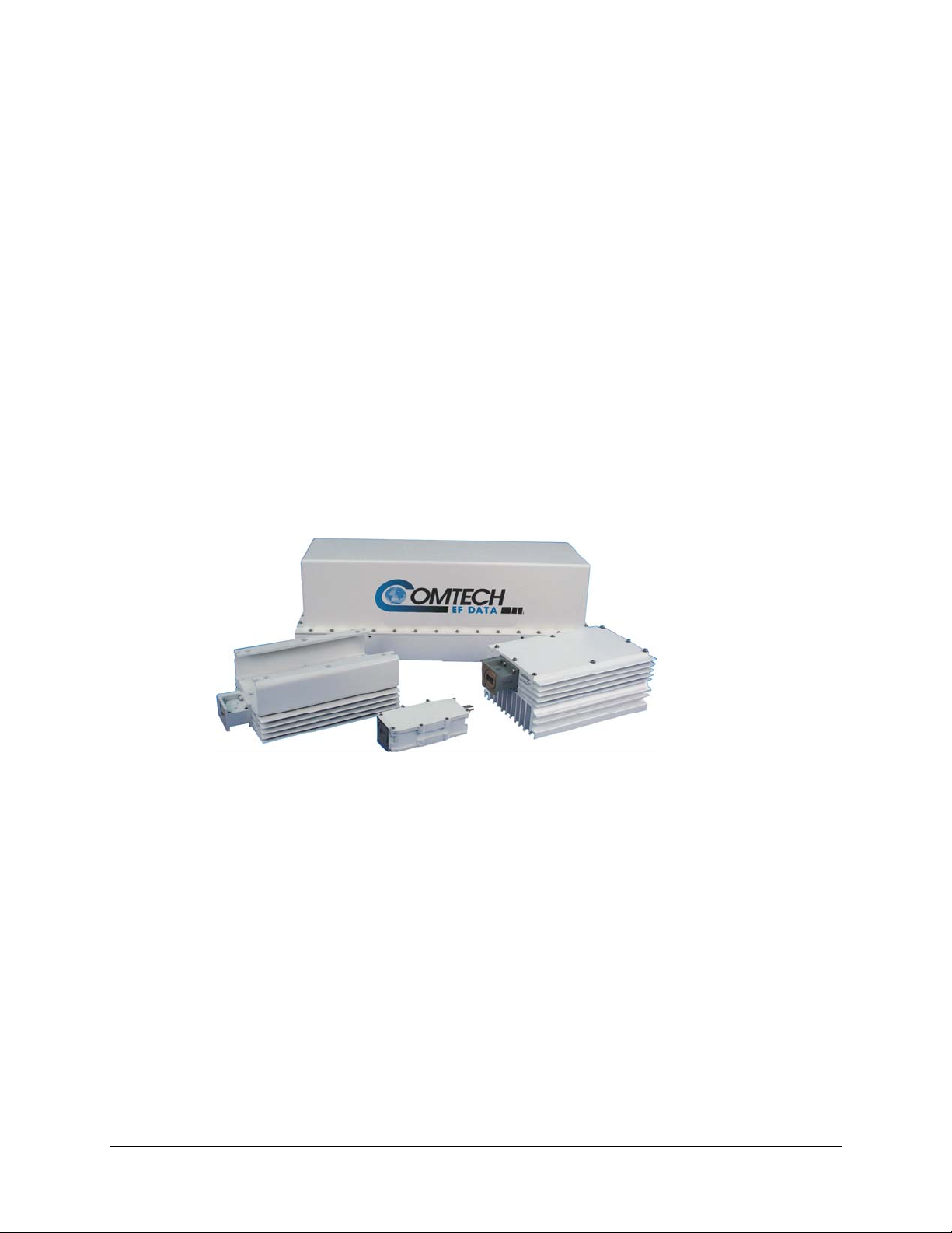
Chapter 1. INTRODUCTION
This chapter provides a description and the specifications for the KST-2000L satellite
terminal system. The terminal system is shown in Figure 1-1.
Figure 1-1.
KST-2000L
1–1
Page 16

Satellite Terminal System Revision 2
Introduction MN/KST2000L.IOM
1.1 Description
The KST-2000L satellite terminal system is a high-performance transceiver designed for
single-thread configuration outdoor operation. The unit transmits in Ku-Band and
receives in L-Band.
1. The converter unit controls external High Power Amplifiers (HPAs).
2. Automatic Gain Control (AGC) from the converter input to the HPA output
assures power output stability over varying conditions.
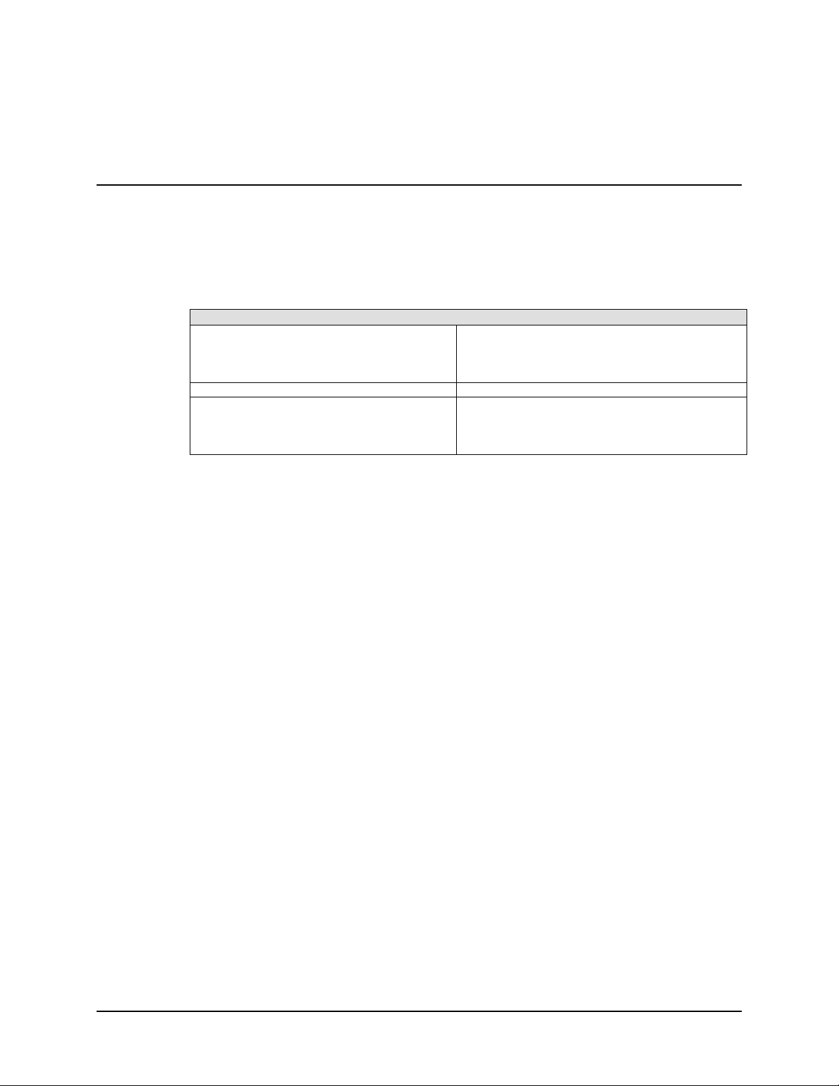
1.1.1 Areas of Operation:
The areas of operation are divided into three sections:
Converter
HPA
Low Noise Block Down Converter
(LNB) Assembly
Convection cooled up/down converter with an internal power
supply and microprocessor-based monitor and control (M&C).
Offered with 2 or 4 W power output capabilities.
LNBs with various frequency coverage are available.
1.1.2 Transmit and Receive Band Coverage
14.0 to 14.5 GHz
10.95 to 11.70 GHz
11.70 to 12.20 GHz
12.25 to 12.75 GHz
Transmit range in 1 MHz steps
LNB-Select: Receive range in 1 MHz steps
1–2
Page 17
Satellite Terminal System Revision 2
Introduction MN/KST2000L.IOM
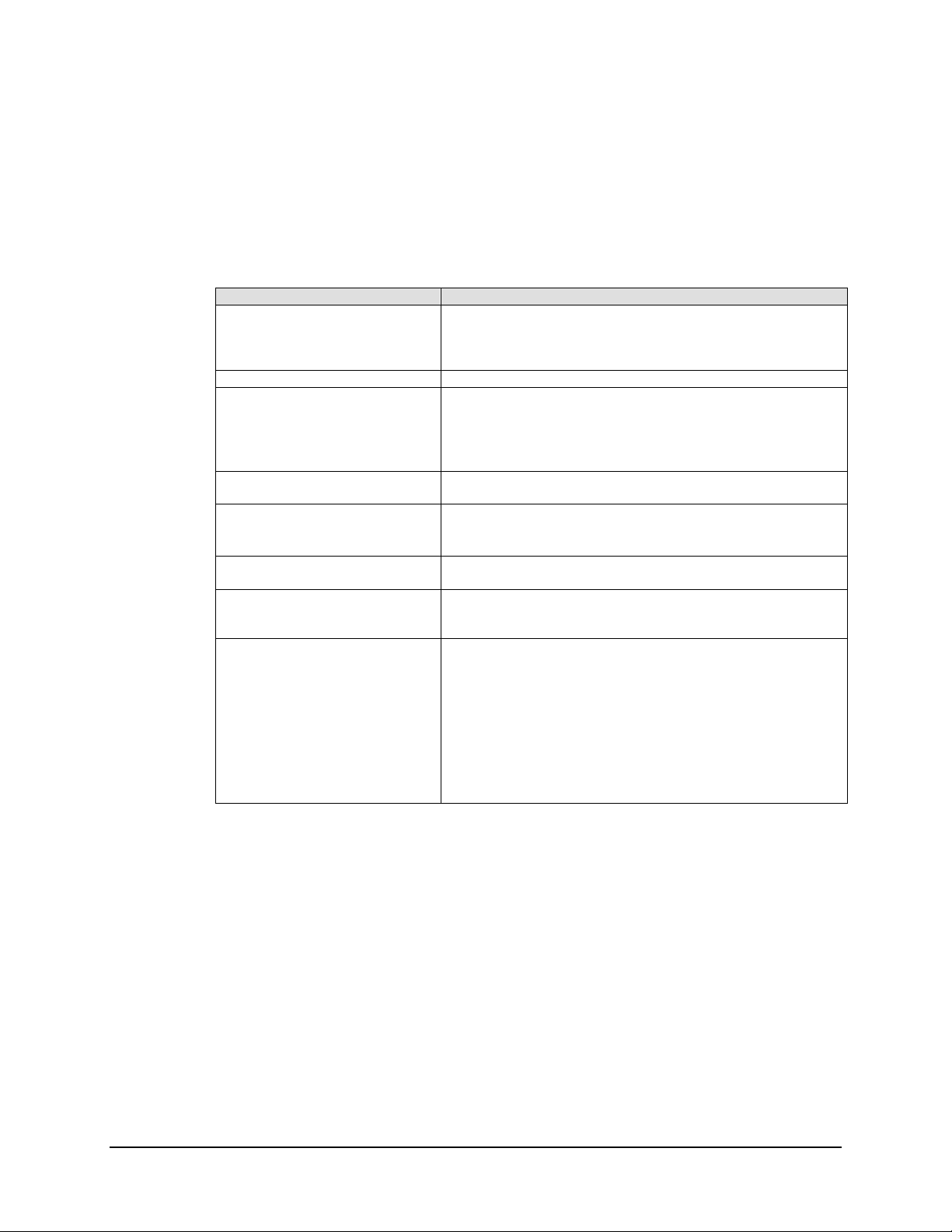
1.1.3 Features
Refer to Table 1-1 for KST-2000L features.
Table 1-1. Features
Parameter Description
Automatic Gain Control The KST-2000L incorporates a closed loop control system that
maintains the system’s conversion gain (as measured from the
IF input to the Ku-Band SSPA output) at the user’s preset
value despite the effects of temperature, aging, and cable loss.
IF Input/Output of 70 /140 MHz Optional
Selectable Serial
Communication
L-Band RX Power Monitor Output An isolated output covers the 950 to 1700 MHz downlink
External LED Indicators for
Power On and Fault Indications
Power Factor Corrected Internal
Power Supply
HPA Options The converter has built-in monitor and control circuitry and
Industry Standards
There are several selectable serial communications protocols
and bandwidths:
• EIA-232, EIA-485, or EIA-422 half-duplex
• Baud Rate = 300 to 19200
bands.
• A blinking GREEN LED indicates prime power ON.
• A steady GREEN LED indicates TX RF Power ON.
• A RED LED indicates a summary fault.
All power supply is power factor corrected and meets all CE
Mark requirements.
functions that operate with the product line Solid-State Power
Amplifiers (SSPAs) with 2 or 4 W output power
• IESS 308 and IESS 309
• FCC radiated emissions requirements
• CE Mark
The system components are completely weatherproof units
designed for the harsh environments of antenna-mounted
systems. The system’s operating parameters can be monitored
and controlled using Windows™ based M&C software with a
personal computer or a hand held KP-10, as described in
Chapter 3.
1–3
Page 18
Satellite Terminal System Revision 2
Introduction MN/KST2000L.IOM
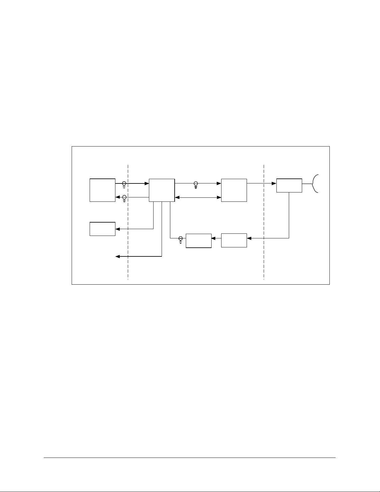
1.1.4 KST-2000L System
A block diagram of a single thread configuration, the system is shown in Figure 1-2.
Note: The modem, the remote M&C, OMT, and the antenna are not part of the system
and are shown for reference only.
Indoor Units
(Reference Only)
TX
Modem
RX
Remote
M&C
L-Band
RX Monitor
70 or 140 MHz
L-Band,
DC Power &
10 MHz Ref.
Ku-Band
M&C (Power)
LNB
HPA
TRF
Converter
Unit
TX
Figure 1-2. KST-2000L System
Ku-Band
Reference Only
Antenna
OMT
Ku-Band
1–4
Page 19

Satellite Terminal System Revision 2
Introduction MN/KST2000L.IOM
The M&C remote control, whose operation is described in Chapter 3, is used to set the
operating parameters of the system such as transmit and receive frequency, gain, etc.; and
to monitor the operation of the system. Connection to the remote M&C is only required
during set up and fault finding.
In the TX (uplink) direction, the converter unit receives a 70 MHz ± 20 MHz signal (140
MHz ± 40 MHz signal optional) at –25 to –45 dBm from a modem via a 50 or 75
Ω
coaxial cable. The converter’s input connector for this signal is a type N, female.
The converter unit performs a block conversion (non-inverted sense) first to S-Band, then
to Ku-Band. The exact frequency output and power level are set by the user via the
remote M&C. The converter output is coupled to an HPA via a coaxial cable with a 50
Ω,
female, type N connector at the converter output.
The HPA receives the Ku-Band input from the converter and amplifies it to the
user-selected level. The converter via the M&C cable supplies prime power for the HPA.
The user via the remote M&C sets the output power of the SSPA, and this output is
connected to the feed of the antenna via a WR-75 waveguide.
In the RX (downlink) direction, the received Ku-Band signal from the antenna is offset in
frequency from the transmitted signal allowing rejection of the transmitted signal by the
Transmit Reject Filter (TRF). The exact RX frequency is set by the user via the remote
M&C. The RX signal is down-converted to L-Band and is amplified in an LNB whose
output is coupled to the converter’s input via a coaxial cable with type N connectors. This
same cable is used to provide prime power (+15 VDC) and a 10 MHz reference to the
LNB.
An output is provided at L-Band (950 to 1700 MHz) to monitor the received signal. This
is particularly useful during set up and fault finding.
1–5
Page 20

Satellite Terminal System Revision 2
Introduction MN/KST2000L.IOM
This page is intentionally left blank.
1–6
Page 21
Chapter 2. Specifications
2.1 Summary of Specifications
Table 2-1. Transmit Specifications
Input Characteristics:
Frequency Range 50 to 90 MHz,
Optional: 100 to 180 MHz
Power Level Operational: -25 to –45 dBm
Survival: -10 dBm
Connector Type N, female
Impedance
VSWR 1.5:1
Output Characteristics:
Frequency Range 14.0 to 14.5 GHz, in 1 MHz steps
Output Power at Flange:
2 Watt 33 dBm 32 dBm
4 Watt 36 dBm 35 dBm
Connector WR-75
VSWR 1.5:1
Transfer Characteristics:
Frequency Sense Non-inverting
System Gain:
(SSG @ 10 dB backoff)
2 Watt 73 dB 63 dB
4 Watt 76 dB 66 dB
User Attenuator Range 0 to 20 dB, 1 dB steps
Gain Stability over temperature
AGC On, Fixed Frequency
AGC Off, Fixed Frequency
Gain variation with frequency:
70 ± 20 MHz
140 ± 40 MHz
50Ω, unbalanced
Typical Pso +25°C
Maximum
2.0 dB p-p
3.0 dB p-p
2.0 dB p-p
3.0 dB p-p
Guaranteed P1 dBm
Nominal
2–1
Page 22
Satellite Terminal System Revision 2
Summary of Specifications MN/KST2000L.IOM
Table 2-1. Transmit Specifications (Continued)
Spurious Signals:
Signal Related
Harmonics
<250 kHz
Non-signal Related
Third Order Intermods -30 dBc (for summed output of 2 signals @ 6 dB for
Group Delay < 10 ns over any 40 MHz
Phase Noise Exceed IESS 308/309 requirements, Limit 2
Frequency Stability
-50 dBc at 6 dB below P1dB
-50 dBc at 6 dB below P1dB
-35 dBc at 6 dB below P1dB
-20 dBm/4 kHz
maximum output power rating)
± 1E-7/Year max
± 1E-8/Temperature
Table 2-2. Receive Specifications
Input Characteristics:
Frequency Range 10.95 to 11.7 GHz (Option A)
11.7 to 12.2 GHz (Option B)
12.2 to 12.75 GHz (Option C)
LNB Noise Figure
LNB Gain 60 dB
Power Level Operational: -125 to –95 dBm
Connector WR-75
Impedance
VSWR 2.5:1
Output Characteristics:
Frequency Range 50 to 90 MHz, in 1 MHz steps
P1dB +10 dBm
Connector Type N, female
Impedance
VSWR 1.5:1
Transfer Characteristics:
Frequency Sense Non-inverting
System Gain: (SSG @ -10 dB backoff) Nominal: 90 dB
User Attenuator Range 0 to 20 dB, 1 dB steps
Gain Stability over temperature
Fixed Frequency
Gain variation with frequency:
± 20 MHz
Entire Band
Spurious Signals:
Signal Related
< 250 kHz
Non-signal Related
P1dBm +10 dBm
Third Order Intermods -30 dBc (for summed output of 2 signals @ 9 dB
Group Delay < 10 ns over any 40 MHz
Phase Noise Exceed IESS 308/309 requirements, Limit 2
Frequency Stability
1.1 dB (85°) Max
Survival: -10 dBm
50Ω, unbalanced
Optional: 100 to 180 MHz
50Ω, Unbalanced
8.0 dB p-p
2.0 dB p-p
6.0 dB p-p
-50 dBc (-5 dBm output)
-35 dBc
-126 dBm max referred to LNB input
below P1dB
± 1E-7/Year max
± 1E-8/Temperature
2–2
Page 23
Satellite Terminal System Revision 2
Summary of Specifications MN/KST2000L.IOM
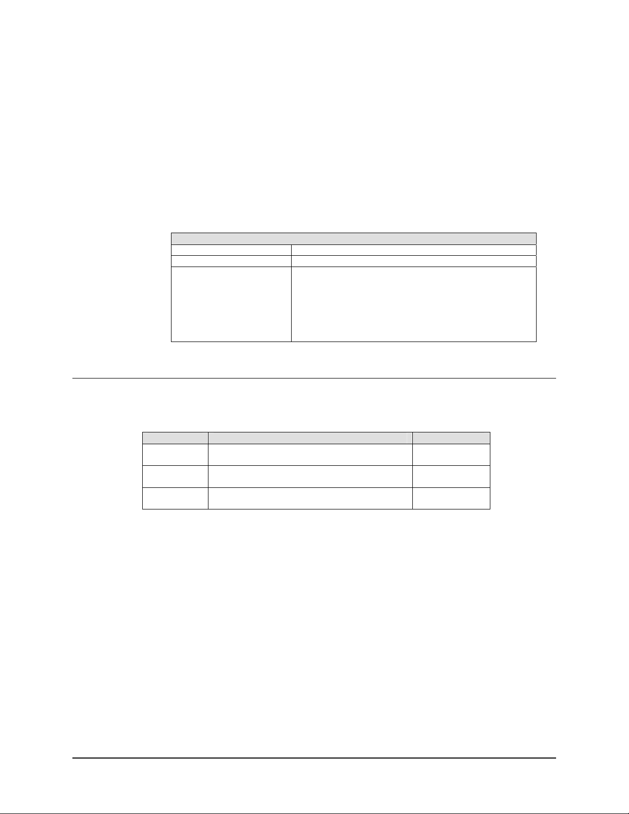
2.1.1 Solid-State Power Amplifier (SSPA)
2.1.1.1 SSPA Monitor and Control Interface
The M&C function for all SSPAs with output powers of ≤ 4W should conform to
requirements of Table 2-3.
Table 2-3. SSPA M&C Specifications
SSPA M&C Specification
Signaling Type EIA-485 (2-wire, half-duplex)
Baud Rate 83333 bps
Data Structure
11 Data Bits
1 Start Bit
1 Stop Bit
8 Data Bits
9 Data Bits
Type Pin Function
M&C Communication A EIA-485 + RX/TX
B EIA-485 – RX/TX
DC Power C +10.5 VDC
D +10.5 VDC
E +10.5 VDC
F +10.5 VDC
G GND
H GND
I GND
J GND
K GND
Note: Connector type is PT00E-12-10S.
= 1 when previous 8 bits represents a slave address; = 0 otherwise
2–3
Page 24
Satellite Terminal System Revision 2
Summary of Specifications MN/KST2000L.IOM
2.1.2 Interface Requirements
2.1.2.1 M&C Interface
The M&C of the system shall be via the M&C connector located on the Converter Unit.
Specifications for the M&C interface are listed in Table 2-4.
Table 2-4. M&C Interface Specification
M&C Interface Specifications
Serial Data Signal Interface (User selectable)
EIA-232
EIA-485 (2-wire, half duplex)
EIA-485 (4-wire, half duplex)
Serial Data Baud Rates (User selectable) 300, 600, 1200, 2400, 4800, 9600, 19200 kbps
Discrete Alarm Outputs
Uplink Summary Alarm
Downlink Summary Alarm
System Summary Alarm
The converter unit and the SSPA are capable of being monitored and controlled via the
data connector whose connections are listed in Table 1-6 using Comtech EF Data
supplied software on an IBM compatible PC running DOS version ≤ 5.0 with at least
192K of available RAM and running with a 386SX processor or greater.
Form ‘C’ Relay Contacts
Form ‘C’ Relay Contacts
Form ‘C’ Relay Contacts
2–4
Page 25

Satellite Terminal System Revision 2
Summary of Specifications MN/KST2000L.IOM
Table 2-5. M&C Functions/Parameters
Pin Signal Description
A -TX/-RX or –TX only (see Notes) -EIA-485 TX/RX or -EIA-422 TX
B -TX/-RX or –RX only (see Notes) -EIA-485 TX/RX or -EIA-422 TX
C +TX/+RX or +TX only (see Notes) +EIA-485 TX/RX or +EIA-422 TX
D +TX/+RX or +RX only (see Notes) +EIA-485 TX/RX or +EIA-422 TX
E RXD EIA-232 RX Data
F RTS EIA-232 Ready-to-Send (tied to CTS)
G TXD EIA-232 TX Data
H DSR EIA-232 Data Set Ready
J GND Ground
K LNA Power +15 VDC to LNA
L LNA Power Return +15 VDC Return from LNA
M RESET Reset (momentary low resets system)
N GND Ground
P CTS EIA-232 Clear-to-Send (tied to RTS)
R GND Ground
S +12V (KP10 Power) KP10 Power Supply Output
T 2/4 WIRE (SEE note) EIA-485/EIA-232 Operation Selection
U UL_FLT_NC Uplink Fault Relay, Closed = Fault
V UL_FLT_COM Uplink Fault Relay, Common
W UL_FLT_NO Uplink Fault Relay, Open = Fault
X DL_FLT_NC Downlink Fault Relay, Closed = Fault
Y DL_FLT_COM Downlink Fault Relay, Common
Z DL_FLT_NO Downlink Fault Relay, Open = Fault
a SUM_FLT_NO Summary Fault Relay, Open = Fault
b SUM_FLT_NC Summary Fault Relay, Closed = Fault
c SUM_FLT_COM Summary Fault Relay, Common
Notes:
1. These signals can be configured as EIA-485, 2-wire, half-duplex or EIA-422, 4-wire,
half-duplex.
2. In 2-wire mode, pins A and B are tied together as are pins C and D.
3. To select 2-wire operation, pin T is left open.
4. Tie pin T to ground for EIA-422 (4-wire) operation.
2–5
Page 26
Satellite Terminal System Revision 2
Summary of Specifications MN/KST2000L.IOM
2.1.3 Internal Data Interface
The individual RF uplink and downlink subassemblies, along with the separate SSPA,
contains a separate microprocessor that will individually monitor and control each
subassembly and communicate via a high-speed serial data bus with the central M&C
subassembly. The communications provides control parameters, status monitoring, and
fault reporting. Specification for the internal data bus are listed in Table 2-6.
Table 2-6. Internal Data Interface Specifications
Internal Data Interface Specification
Signaling Type Balanced Multipoint EIA-485, 2-wire
Baud Rate 83333 bps
Data Structure:
11 Data Bits:
1 Start Bit
1 Stop Bit
8 Data Bits
or 9 Data Bits
= 1 when previous 8 bits represents a slave address; = 0
otherwise
2.2 Size and Weight Specifications
Table 2-7. Size and Weight Specifications
Unit Size Weight
Converter 21.75L x 8.25W x 8.0H inches
(54.48L x 20.95W x 20.3H cm)
2W SSPA 12.95L x 6.0W x 3.9H inches
(32.89L x 15.24W x 9.9H cm)
4W SSPA 12.95L x 6.0W x 3.9H inches
(32.89L x 15.24W x 9.9H cm)
30 lbs (13.6 kg)
7 lbs (3.17 kg)
7 lbs (3.17 kg)
2–6
Page 27

Satellite Terminal System Revision 2
Summary of Specifications MN/KST2000L.IOM
2.3 Environment Specifications
Table 2-8. Converter Unit and SSPA Environmental Requirements
Parameter Requirements
Temperature
Thermal Gradient
Humidity
Precipitation MIL-STD-810, Method 506.2 Proc I, 5.2 inches/hour
Salt Fog MIL-STD-810, Method 506.2
Sand and Dust MIL-STD-810, Method 509.2
Altitude MIL-STD-810, Method 510.1
Solar Radiation
ES Discharge Operational: 10 KV
Shock Operation: 10 g for 10 mS (half-sine) on three axis
Vibration Survival – 5minute resonant dwell at four major resonances at 1 g
Frequency
Operational – 0.91 g
Frequency
Operation: -40 to 55°C (-40 to 131°F)
Survival: -50 to 75°C (-58 to 167°F)
40°C/hour
10°C/15 minute
0 to 100% relative at -40 to 55°C (-40 to 131°F)
95% at 65°C/72 hours
Operational: 0 to 15,000 ft
Survival: 0 to 50,000ft
360 BTU/ft
2
/hr at 50°C (122°F)
Survival: 15 KV
Survival: 40 g for 10 mS (half-sine) on three axis
peak.
Survival – 2.41g
of random vibration as listed below, 10
rms
minutes/axis
Slope
5 to 100 Hz
100 to 137 Hz
137 to 350 Hz
350 to 500 Hz
500 Hz
0
-6 dB/oct
0
-6 dB/oct
0
0.20 g
-
0.0107 g
-
0.0052 g
of random vibration as listed, 10
rms
minutes/axis
Slope
5 to 350 Hz
350 to 500 Hz
500 Hz
0
-6 dB/oct
0
0.0015 g
-
0.00074 g
2
/Hz
PSD
2
/Hz
2
/Hz
PSD
2
/Hz
2
/Hz
2–7
Page 28

Satellite Terminal System Revision 2
Summary of Specifications MN/KST2000L.IOM
2.4 CE Certification
Table 2-9. CE Certification
Specification Description/Test
EN55022 Conducted and Radiated Emissions
EN50082-1 Immunity
• Fast Transmit Burst
• Static Discharge
• Radiated Immunity
EN60958 Safety
2.5 Terminal Assemblies
Table 2-10. Part Numbers for Various Equipment
Part Number Description Comments
System/FW Configuration:
FW/8439-1 TX/RX Duplex System/FW Configuration
Primary Input Power:
CA/84914-0223 90-264 VAC
TX Output Power:
KT/2819(2) 2 Watt CEFD SSPA 13.75 – 14.50 GHz
KT/2819 (2) 4 Watt CEFD SSPA 13.75 – 14.50 GHz
RX KLNB:
RF/LNB-10.9-11.7
RF/LNB-11.7 to 12.2
RF/LNB-12.2-12.7
RX Transmit Reject Filter:
RF/TRF-KU-WR75R2
RF/TRF-KU-WR75G
IF Frequency
KT/8766-2 70 MHz, IF
KT/8766-2 140 MHz, IF
TX Interlink Cables
CA/3722-2 5-Foot Cables
CA/3722-8 10-Foot Cables
CA/3722-9 15-Foot Cables
CA/3722-7 20-Foot Cables
RX Interlink Cables
CA/3722-2 5-Foot Cables
CA/3722-8 10-Foot Cables
CA/3722-9 15-Foot Cables
CA/3722-7 20-Foot Cables
10-95 to 11.70 GHz
11.70 to 12.20 GHz
12.25 to 12.75 GHz
Right-Angle, TRF
Straight, TRF
None (TX only) or No KLNB
KT/2819 for selected RX KLNB
None (TX only) or No KLNB
2–8
Page 29

Satellite Terminal System Revision 2
Summary of Specifications MN/KST2000L.IOM
Table 2-10. Part Numbers for Various Equipment (Contd)
Part Number Description Comments
Antenna Mounting Hardware:
KT/8324-1 Spar (1 x 2 in) Mount Base Unit Only
KT/8326-1 Spar (2.5 x 2.5 in) Mount Base Unit Only)
KT/7805-1 Spar (1 x 2in) Mount Prodelin Offset 5.25 in. Interface
SSPA/LNA Feed Mount
KT/7945-1 Spar (1 x 2in) Mount Prodelin Offset 3.74 in. Interface
SSPA/LNA Feed Mount
KT/7595 Spar (2.5 x 2.5) Mount Channel Master 5.29 in. Interface
SSPA/LNA Feed Mount
KT/8324-1/KT/8094-1 Spar (1 x 2) Mount for
Amplifier
KT/8326-1/KT/8094-1 Spar (2.5 x 2.5) Mount for
Amplifier
TX Flexible Waveguide:
KT/5860 5-Foot Flex Waveguide
KT-5860-1 3-Foot Flex Waveguide
KT/5860-2 2-Foot Flex Waveguide
RX Flexible Waveguide:
KT/5860 5-Foot Flex Waveguide
KT-5860-1 3-Foot Flex Waveguide
KT/5860-2 2-Foot Flex Waveguide
Handheld Keypad Controller:
KT/8078 KP10: RS-232
KT/8078-1 KP10: RS-485
KT/8078-2 KP10: RS-422
Mast Pipe Mount for Base Unit
Mast Pipe Mount for Base Unit
Notes:
1. Several items of equipment are customer-select.
2. All inquiries shall be directed to Comtech EF Data Customer Support
department.
2–9
Page 30

Satellite Terminal System Revision 2
Summary of Specifications MN/KST2000L.IOM
This page is intentionally left blank.
2–10
Page 31

Chapter 3. Connector Pinouts
This chapter provides system equipment and external connections information. Refer to
Chapter 6 for installation procedures specific to particular mounting applications.
3.1 System Equipment Information
3.1.1 System Components
The standard components delivered with a single thread system include:
QTY Description
1 Base converter unit
1 HPA
1 LNB
1 12ft (3.66m) Prime power cable for the converter unit
As Required 5ft (1.52m) Interlink cabling
As Required Mounting hardware for a spar mounted offset antenna. (see Note)
Note: Antenna type shall be indicated when ordering the KST-2000L.
3–1
Page 32

Satellite Terminal System Revision 2
Connector Pinous MN/KST2000L.IOM
3.1.2 Description of Options
Table 3-1 lists the various equipment options, and Table 3-2 lists the available spare
parts.
Table 3-1. Description of Options
LNB OPTIONS (discrete narrow bands at 1.1db max NF only):
10.95 to 11.70 GHz Europe
11.70 to 12.20 GHz North American
12.25 to 12.75 GHz Aussat
MOUNTING HARDWARE OPTIONS:
Standard Prodelin spar offset antenna
Standard Channel Master spar offset antenna
Non-standard single thread converter pole-mount Kit
No mounting hardware beyond the “pick off points” on the completed assembly
For mounting requirements outside those previously indicated, please consult the factory for
availability.
CABLING OPTIONS:
No RF or control cabling. Includes only the prime power cable(s) and applicable MS
connectors
For cabling requirements outside those previously indicated, please consult the factory for
availability.
3.1.3 Spare Parts
Description P/N
2 Watt SSPA (white) PL/8308-1
4 Watt SSPA (white) PL/8235-1
M&C PCB assembly PL/8314-1
10.95 to 11.7 GHz Europe and also Intelsat
(11.2 to 11.7 GHz) KLNB (white)
11.7 to 12.2 GHz North American KLNB
(white)
12.25 to 12.75 GHz Aussat KLNB (white) RF/LNB-KU-60-753
10ft RF heliax “N” cable CA/3722-8
12ft RF heliax “N” cable CA/3722
15ft RF heliax “N” cable CA/3722-9
Base A/C converter power supply PS/AC150W02P01
Transmit reject filter (right angle) RF/TRF-KU-WR75R1
Transmit reject filter (straight) RF/TRF-KU-WR75G
Table 3-2. Spare Parts
RF/LNB-KU-60-751
RF/LNB-KU-60-752
3–2
Page 33

Satellite Terminal System Revision 2
Connector Pinouts MN/KST2000L.IOM
3.2 Electrical Connections
3.2.1 Converter Unit
The external connections on the converter unit are shown in Figure 2-1 and listed in
Table 3-3. The connectors are described in the following paragraphs.
TRANSCEIVER
Figure 3-1. I/O View of KST-2000L Converter Unit
3–3
Page 34

Satellite Terminal System Revision 2
Connector Pinous MN/KST2000L.IOM
Table 3-3. Converter Unit External Connections
Ref. Des. Name Connector Type Function
J1 PRIME POWER 3 pin circular Male Prime AC Power Input
J2 REMOTE 26 pin circular, Female Remote M&C Interface
J3 IF IN Type N, Female TX IF Input 70 MHz (Optional: 140 MHz)
J4 IF OUT Type N, Female RX IF Output 70 MHz (Optional: 140 MHz)
J5 RX MON Type N, Female Ku-Band Receive Monitor (950 to 700MHz)
J6 RF OUT Type N, Female 14.00 to 14.50 GHz TX out to HPA
J7 RF IN Type N, Female 950 to 1700 MHz from LNB
J8 HPA 10 pin circular, Stet HPA M&C Interface
3.2.1.1 Prime Power Connector (J1)
Prime power is supplied to the converter unit through a 3–pin circular male connector
(J1). Prime power input requirements are 85 to 264 VAC, 47 to 63 Hz, 100 watts. The J1
connections are listed in Table 3-4 for pin assignments.
Note: Pin C is adjacent to the connector notch.
Table 3-4. Prime Power Input (J1) Pin Assignments
Pin Function
A Line
B Neutral
C Ground
3–4
Page 35

Satellite Terminal System Revision 2
Connector Pinouts MN/KST2000L.IOM
3.2.1.2 Remote Connector (J2)
The Remote Connector (J2) is a 26-pin, circular, female connector. It is used to allow
remote control and monitoring of KST-2000L operating parameters. Interface is via EIA232, EIA-485, or EIA-422 half-duplex. Refer to Table 3-5 for pin assignments.
Note: This cable must be assembled by the user. Figure 3-2 shows the connections for an
EIA-232 adapter for use with a PC COM port.
Table 3-5. Remote M&C Connector (J2) Pin Assignments
Pin Signal Description
A -TX/-RX or –TX only (see Note) – EIA-485 TX/RX or – EIA-422 TX
B -TX/-RX or –RX only (see Note) –EIA-485 TX/RX or – EIA-422 RX
C +TX/+RX or +TX only (see Note) + EIA-485 TX/RX or + EIA-422 TX
D +TX/+RX or +RX only (see Note) + EIA-485 TX/RX or + EIA-422 RX
E RXD EIA-232 receive data
F RTS EIA-232 ready to send (tied to CTS)
G TXD EIA-232 transmit data
H DSR EIA-232 data set ready
J GND Ground
K LNB Power +15 VDC to LNB
L LNB Power Return +15 VDC Return from LNB
M RESET Reset (momentary low resets system)
N GND Ground
P CTS EIA-232 clear to send (tied to RTS)
R GND Ground
S +12V (KP10 Power) KP10 power supply output
T 2/4 wire (see note) EIA-485/EIA-422 operation selection
U UL_FLT_NC Uplink fault relay, closed = fault
V UL_FLT_COM Uplink fault relay common
W UL_FLT_NO Uplink fault relay, open = fault
X DL_FLT_NC Downlink fault relay, closed = fault
Y DL_FLT_COM Downlink fault relay common
Z DL_FLT_NO Downlink fault relay, open = fault
a SUM_FLT_NO Summary fault relay, open = fault
b SUM_FLT_NC Summary fault relay, closed = fault
c SUM_FLT_COM Summary fault relay, common
Note: These signals can be configured as EIA-485, 2-wire, half-duplex or EIA-422,
4-wire, half-duplex. In 2-wire mode, pins A and B are tied together as are pins C and D.
To select 2 wire operation, pin T is left open. Tie pin T to ground for EIA-422 (4-wire)
operation.
3–5
Page 36

Satellite Terminal System Revision 2
Connector Pinous MN/KST2000L.IOM
Comtech EF Data: CN/STPG26M01
P1
PT06E16-26P(SR)
J
P
E
F
G
H
26 PIN
EIA-232 ADAPTER CABLE
Figure 3-2. Serial (EIA-232) Adapter Cable Wiring Diagram
3.2.1.3 IF IN Connector (J3)
The IF IN connector (J3) is a Type N, female connector used to connect the IF at 70 MHz
(140 MHz optional) at –25 to – 45 dBm from the modem to the converter unit. Either
50Ω or 75Ω cables may be used to connect to J3.
GND
CTS
RD/R
RTS
TD/T
DSR
5
9
4
8
3
7
2
6
1
MALE
3.2.1.4 IF OUT Connector (J4)
The IF OUT connector (J4) is a Type N, female connector used to connect the IF at
70 MHz (140 MHz optional) from the converter unit to the modem. Either 50Ω or 75Ω
cables may be used to connect to J4.
3.2.1.5 RX MON Connector (J5)
The RX Mon (J5) connector provides the received (downlink) signal at L-Band (950 to
1700 MHz) for monitoring. This signal has a gain of 20 dB relative to the carrier. J5 is a
Type N, female connector. Nominal output impedance is 50Ω.
3–6
Page 37

Satellite Terminal System Revision 2
Connector Pinouts MN/KST2000L.IOM
3.2.1.6 RF OUT Connector (J6)
The RF OUT connector (J6) is a type N, female, 50Ω connector used to connect the
converter unit’s output at Ku-Band (uplink) to an HPA. Power output at 1 dB
compression is +15 dBm minimum.
3.2.1.7 RF IN Connector (J7)
The RF IN connector (J7) is a type N, female, 50Ω connector used to connect the LNB’s
output at L-Band (downlink) to the converter unit.
3.2.1.8 HPA Connector (J8)
The HPA connector (J8) is a 10 pin circular, female (ITT #KPT02E-12-105) connector
used for HPA M&C and power functions. Refer to Table 3-6 for pin assignments for 2
and 4 watt SSPAs.
Table 3-6. HPA Connector (J8) Pin Assignments (2 and 4W SSPAs)
Pin Signal Description
A IPA Communications line A
B IPB Communications line B
C +10V +10V Power Supply Output
D +10V +10V Power Supply Output
E +10V +10V Power Supply Output
F +10V +10V Power Supply Output
G +10V_RTN +10V Power Supply Return
H +10V_RTN +10V Power Supply Return
J +10V_RTN +10V Power Supply Return
K +10V_RTN +10V Power Supply Return
3.2.1.9 2 and 4 Watt SSPA RF Connections
3–7
Page 38

Satellite Terminal System Revision 2
Connector Pinous MN/KST2000L.IOM
The 2 and 4 Watt SSPAs have a Type N, female (50Ω) connector (J1) at one end for the
Ku-Band input and a WR-75 waveguide isolator (J2) at the other end for the Ku-Band
output.
3.2.1.10 LNB Connections
Note: The power supply for the LNB can be supplied by the KST-2000L.
The RF input of the LNB is a WR-75 waveguide flange. The RF OUT/REF/PWR IN
connector of the LNB is a type N, 50Ω connector. It supplies the block-converted output
of 950 to 1700 MHz. It accepts +15 V at 400 mA, and a 10 MHz reference signal
supplied by the converter unit.
3–8
Page 39

Chapter 4. OPERATION
This chapter describes the procedures for initial testing of a KST-2000L system, and describes each major system function.
4.1 Initial Setup
This section details the procedures necessary to laboratory test a KST-2000L system for
the first time. Refer to Figure 4-1 for system setup.
PC
OR
KP10
TO DEMOD
FROM MOD
EARTH
GROUND
AC POWER
SOURCE
J2 REMOTE
J4 IF OUT
J3 IF IN
GND
(ERDE)
J1 PRIME
PO WER
RF OUT J6
HPA J8
RF IN J7
Figure 4-1. System Block Diagram
MON
J1
J2
HPA
J3
LNB
TERM
4–1
Page 40

Satellite Terminal System Revision 2
Operation MN/KST2000L.IOM
Note: Ensure that the termination selected for the HPA output is sized to handle the HPA output
power.
1. Apply power to the KST-2000L. After a few seconds ensure that the green TX
ON LED is flashing, and the fault LED is extinguished. Refer to Section 4 if this
is not the case.
2. Using a KP-10 or PC equipped with a terminal or Windows based M&C program, ensure that you can communicate to the system M&C, via J2, remote connector. (Refer to M&C software manual, part number MN/M&CWIN.IOM)
Default Communication Parameters Address 1
Baud Rate 9600
Parity even
Stop bits 2
Data length 7 bits
If the communication parameters for the system are not known, the Windows
based M&C system has a facility that will search all combinations of address,
baud rate, and parity until communication is established with the system.
Using the KP-10 or terminal program, send a miscellaneous command such as
EQUIPMENT TYPE (see appendix B.8) and confirm a response is displayed.
The Windows based status screen will turn from red to gray when communication with the KST-2000L is established.
4.1.1 Uplink Setup
1. Apply a 70 MHz (140 MHz) signal at a known level between –25 and
–45 dBm to the IF IN (J3) connector of the KST-2000L.
Note: This assumes that the AGC function is selected as ON. The AGC will
not function below a – 45 dBm input level. If the AGC function is selected
as OFF, lower input levels can be used limited only by noise. See section
3.12 for more information on the AGC function.
2. Set the up converter to the desired RF transmit frequency using the appropriate
commands from the KP10 terminal, or Windows M&C. See the up converter
frequency select command (Appendix B.3). If an error message is received, see
Appendix B.2.3 to determine the cause.
3. Before proceeding, ensure that the HPA is properly terminated. If a directional
coupler and termination is used or an attenuator is used, note the value.
4. Enable external faults, execute the appropriate HPA Power commands. See section B.4 HPA commands.
4–2
Page 41

Satellite Terminal System Revision 2
Operation MN/KST2000L.IOM
5. Turn the RF output of the up converter ON. See appendix B.3 system configuration commands. There should be no up converter faults at this time.
6. Using an appropriate frequency measuring device, ensure that the output of the
HPA (measured through the coupler or attenuator) is at the correct frequency.
Note: The internal, high-stability oscillators frequency can be fine tuned using the reference frequency adjust command. See Appendix B.3. Allow at
least 30 minutes warm-up before adjusting the oscillator.
7. Using an appropriate RF power measuring device, set the up converter attenuation until the power measured at the output of the coupler or attenuator is at the
correct value. See Appendix B.3.
8. Turn the RF output of the up converter off. See Appendix B.3.
4.1.2 Downlink Setup
1. Apply a signal in the appropriate receive frequency range according to the following table at a known level (approximately –95 dBm) to the LNB input.
10.95 to 11.70 GHz
11.70 to 12.20 GHz
12.25 to 12.75 GHz
a. If the LNB is using power supplied by the KST-2000L, enable the LNB
power – see section B.5.
b. After a 10-minute warm-up, perform an LNB calibration, and enable LNB
faults if desired. See Appendix B.5.
2. Set the down converter to the desired RX operating frequency. See Appendix
B.3. There should not be any existing receive system faults. See Appendix B.9.
3. Using an appropriate power measuring device attached to the IF OUT connector
(J4), set the down converter attenuator until the desired downlink gain is attained. See section B.3.
Note: At this point there should be no existing faults.
4. Execute a Clear Stored Faults command to clear the fault log (see Appendix
B.9), wait a few moments, and execute a System Fault Status command to verify.
5. Remove the AC power from the unit, remove the 70 MHz (140 MHz) test
source, remove the RX signal source, and remove the coupler/attenuator from
the HPA.
4–3
Page 42

Satellite Terminal System Revision 2
Operation MN/KST2000L.IOM
6. The system is ready for final installation to the antenna feed. Perform the rest of
the system alignment to applicable international, national, or local regulations.
4.2 Monitor and Control (M&C)
The Monitor and Control (M&C) monitors the KST-2000L and provides configuration
updates to the up converter, down converter, and HPA when necessary. Refer to
Figure 4-2.
EXT
OUTPUT
FAULT
RELAY
72 Mhz
Generator
10 Mhz
Output
485
Module
COMM
232 / 422
Analog
MON
M & C
2
IC
RAM
LNB
CTL
LEDROMRAM
EXT
INPUT
10 MHz
OCVCXO
Figure 4-2. Monitor and Control (M&C) Block Diagram
The KST-2000L configuration parameters are maintained on battery locked RAM, which
provides recovery after power down.
The M&C functions include extensive fault and status reporting. All KST-2000L functions are accessible through the remote communications interface.
The M&C is composed of the following sections:
• Microcontroller and UART • D to A and A to D converters
• ROM • RAM
• Fault relays • 10 MHz/72MHz Oscillators
• LNB power control
• Inter-module communication interface
The microcontroller is an Intel 80C32 operating at 16 MHz. The micro-controller contains 256 bytes of internal RAM. The external ROM is 29F020 (256 kbytes). The battery
backed RAM is 8 kbytes in size.
The non-volatile RAM allows the KST-2000L to retain configuration information without prime power for 1 year.
4–4
Page 43

Satellite Terminal System Revision 2
Operation MN/KST2000L.IOM
The UART supports serial asynchronous communication (remote port) with a maximum
data rate of 19,200 bit/s. The communications type can be EIA-232, EIA-485 (2-wire), or
EIA-422 (4-wire) half duplex.
The DAC supplies a voltage that fine tunes the reference oscillator operating frequency.
The ADC monitors the internal power supply voltages, as well as external temperature
and analog inputs from SSPAs.
The three fault relay outputs are failsafe. They will indicate a fault in the event of a power
outage. The three relays are uplink fault, downlink fault, and summary fault.
The M&C has a switching regulator that can generate +15VDC at 400 mA to power an
external LNB. This voltage can be enabled or disabled via the remote interface. The
M&C monitors the LNB current and generates a fault if the LNB current draw increases
or decreases excessively.
The M&C communicates status and control information to the up converter, down converter and SSPAs via a high speed RS-485 interface.
The 10 MHz OCVCXO is a high stability, low phase noise, crystal oscillator. It has a tuning voltage input which can be used to fine tune the oscillator frequency. The M&C generates a bias voltage which can be changed remotely to set the oscillator frequency.
The 72 MHz VCXO is phase locked to the 10 MHz reference. The 72 MHz output of the
VCXO is amplified and distributed throughout the KST-2000L to provide a reference frequency for the up converter and portions of the down converter.
4–5
Page 44

Satellite Terminal System Revision 2
-
Operation MN/KST2000L.IOM
4.3 Up Converter Description
The up converter accepts a 70 MHz (140 MHz) IF input signal and translates it to an output frequency in the range of 13.750 to 14.500 GHz. The up converter consists of two
modules: the IF to S-Band module and the S to Ku-Band module.
The IF to S-Band module translates the 70 MHz (140 MHz) IF input to an output frequency in the range of 2,330 to 3,080 MHz. Refer to Figure 4-3 for a block diagram of
the IF to S-Band module.
MX1 MX2
70/ 140
MHZ
GAIN
CONTROL
DETECT
72 MHZ
REF
L01
1035 (70)
960 (140)
Figure 4-3. IF to S-Band Converter Module Block Diagram
L02
3.435-4. 185 (70)
3.430-4. 180 (140)
2330
3080
MHZ
The 70 MHz (140 MHz) IF input is first amplified, and then applied to an electronically
variable attenuator. This attenuator is controlled via the local M&C to provide calibrated
1dB attenuation steps over a 20 dB attenuation range. The signal is then amplified and
heterodyned with a fixed frequency LO1. The desired sideband of this process is selected
via bandpass filtering and applied to the second up conversion stage MX2. LO2 is a low
noise synthesized source, whose output covers 750 MHz in 1 MHz steps. The output of
the second up conversion stage is a signal in the 2,330 to 3,080 MHz frequency range.
This signal is applied to the input of the S to Ku-Band module.
This module is slightly different for the 70 MHz and 140 MHz IF input options. As
shown in Figure 4-3, the LOs are tuned to different frequencies and filtering is different.
4–6
Page 45

Satellite Terminal System Revision 2
Z
F
Operation MN/KST2000L.IOM
23303080 MHZ
L03
16.830
GHZ
72 MHZ
REF
Figure 4-4. S to Ku-Band Up Converter Module
The S to Ku-Band up converter module (Figure 4-4) performs block up conversion of the
2,330 to 3,080 MHz signal input to an output in the range of 13.750 to 14.500 GHz. This
is done by mixing the IF input with a fixed frequency Dielectric Resonator Oscillator
(DRO), operating at 16.830 GHz. The correct sideband of this process is amplified and
filtered before being applied to the isolated output of the module.
4.4 L-Band to IF Down Converter Description
The L-Band to IF down converter (Figure 4-5) accepts an RF input in the frequency
range of 950 to 1,700 MHz and translates it to an output of 70 (140) MHz. The RF input
to this module is supplied from an externally mounted LNB.
13.750 t o
14.500 GH
950- 1700
MHZ
Fro m LN B
L-BAND
MONITOR
INTERFACE
72 MHZ
RE
1.6- 2. 35
GHZ
Figure 4-5. Ku-Band to IF Down Converter Block Diagram
The 950 to 1,700 MHz input is first pre-selected and then heterodyned with a local oscillator in the range of 1.6 to 2.35 GHz to generate the first IF signal of 650 MHz. The 650
MHz signal is then mixed with 790 or 720 MHz to generate the 70 or 140 MHz output.
The IF output frequency of the second down conversion stage is then amplified and applied to a 0 to 20 dB step attenuator with 1 dB steps. The overall Ku-Band down converter tunes in a frequency step-size of 1 MHz across the 950 to 1700 MHz band.
This module is slightly different for the 70 and 140 MHz options.
4–7
720 (70)
790 (140)
0-2 0 dB STEP
ATTENUATOR
70/ 1 40
MHZ
Page 46

Satellite Terminal System Revision 2
Operation MN/KST2000L.IOM
4.5 Automatic Gain Control (AGC)
The KST-2000L incorporates a closed-loop Automatic Gain Control (AGC) function that
maintains the system gain, as measured from the TX IF input to the Ku-Band output of
the SSPA, at the user’s preset value despite the effects of aging, operating temperature, or
cabling loss. This is not a Automatic Level Control (ALC) function, but a true AGC that
maintains the gain of the system constant independent of input and output absolute levels.
This is important to multicarrier operation, when individual carriers turn On/Off and the
level of the remaining carriers must remain unaffected. The transceiver can be set to operate in either the AGC, non-AGC, or MANUAL gain mode.
4.5.1 Operation
The AGC function is implemented by using two calibrated RF detectors.
• The first detector monitors the TX input (70 or 140 MHz; amplitude range of
–25 to –45 dBm). The DC voltage from the detector is converted to a digital
word in an A/D converter and read by the main processor.
• The second detector monitors the output signal of the SSPA. This detector is calibrated for five frequencies over the output frequency range. Additionally, the
second detector calibration covers output power from the saturation point of the
amplifier down to 30 dB (approximately) below saturation.
The calibration data is stored in a non-volatile memory within each SSPA making all
SSPAs interchangeable without loss of system gain accuracy. The estimate of output
power corresponds to the detector voltage linearly interpolated between nearby frequency
and power steps stored in memory. The main processor reads the estimated output power
from the SSPA and computes an error function as follows:
Gain Error = SSPA Output Power – Input Power – Gain_Max + UCA
Where Gain_Max is the maximum specified gain of the entire transceiver (converter unit
plus SSPA) and UCA is the value of the up converter attenuator and is set by:
<add/UCA_xx.x (Appendix B)
The main processor processes this data and generates an analog voltage that adjusts the
up converter attenuator to drive the error function to zero.
When the uplink AGC is enabled (<add/UAGC_ON) the display value of UCA will include a decimal point. Attenuation is adjustable over a range of 0 to 20 dB in 1 dB steps.
When the uplink AGC is disabled (<add/UAGC_OFF) the displayed value of UCA does
not include the decimal point.
4–8
Page 47

Satellite Terminal System Revision 2
Operation MN/KST2000L.IOM
4.5.2 Fault and Error Response
Table 4-1 shows how the AGC system reacts to power outages, system faults and operation outside the specified limits.
Table 4-1. AGC Fault and Error Response
Problem Response/Notes
If the transceiver prime power fails The UCA value is effect prior to the failure is restored on power up.
If the input signal (70 or 140 MHz) is removed
or is set to ≤ –45dBm.
If the user enters a value of UCA that is low for
a set input level.
If the input power is increased, such that the
SSPA is driven into saturation.
Loop fault occurs when the Gain Error is nonzero for >5 out 255 iterations of the processor
control loop.
INSUFFICIENT INPUT POWER fault is generated when the IF input power transitions from
normal power to low power (< – 45 dBm).
EXCESSIVE INPUT POWER fault is generated when the IF input power transitions from
normal power to high power (> –25 dBm).
The LOOP, INSUFFICIENT INPUT POWER, and EXCESSIVE INPUT POWER faults can be displayed
by issuing the AGC current faults command (<add/AGS_) . The allowed ranges of IF input power and
UCA settings are limited by the SSPA saturation and detector range to the shaded area defined in Figure 4-
6.
1. The internal Up Converter attenuator is set to its maximum value (minimum gap).
2. The value of UCA is not affected.
3. The output power will slowly increase for several seconds until the gain
error reaches zero, when the input signal is reapplied.
1. The SSPA will be driven into saturation and the value of UCA will
automatically increase (Gain decreased) in steps of 1 dB until the SSPA
output power is below saturation.
2. The new (increased) value of UCA is displayed at the user’s interface.
Even if the input power is reduced, the new value of UCA will remain
fixed.
1. The value of UCA is increased (Gain decreased) in steps of 1 dB until
the SSPA is below saturation.
2. The new value of UCA is displayed at the user’s interface. Even if the
input power is reduced, the new value of UCA will remain fixed.
1. A top level AGS_Fault is reported.
2. Excessive cable loss between the converter unit and the SSPA can cause
this condition.
3. If the AGC is enabled and the RF is commanded Off (<add/RF_OFF),
this fault is registered.
Under this condition, a top level AGS_fault is reported and the internal up
converter attenuator is set to its maximum value (minimum RF output). The
value of UCA is not affected. When the input signal increases above –45
dBm, the output power will slowly increase for several seconds until the gain
error reaches zero.
Under this condition, a top level AGS_Fault is reported. If the combination of
the input power and the up converter attenuator is such that the SSPA is
driven into saturation, the value of the UCA will automatically increase in
steps of 1 dB until the SSPA output power is below saturation. The new value
of UCA is displayed at the user’s interface. Even if the input power is reduced, the new values of UCA will remain fixed.
4–9
Page 48

Satellite Terminal System Revision 2
Operation MN/KST2000L.IOM
SSPA Power Saturation
Boundary
Allowed Up Converter
Attenuation, dB (UCA)
-50 -45
Figure 4-6. AGC Operating Region
4.5.3 Manual Gain Operation
With AGC disabled, the closed loop control of the uplink path is disabled. The SSPA
saturation, INSUFFICIENT INPUT POWER, EXCESSIVE INPUT POWER, and LOOP
faults are not monitored or reported as faults. The status of the AGS_fault is displayed as
OK. In this mode, the system gain is not accurately defined as in the AGC mode, because
the accuracy of the up converter’s programmable attenuator and the static gains of the uplink amplifiers determine the gain.
When this mode is selected, UCA will display as an integer (with no decimal point), and
the allowed range of the UCA is 0 to 55 dB in 1 dB steps. The accuracy of the attenuator
is not guaranteed and degrades at high values.
-40
Allowed IF Input Power Range,
-35 -30
dBm
-25
-20
4–10
Page 49

Chapter 5. FAULT INDICATION
AND ISOLATION
This section describes fault indication and isolation methods for the KST-2000L system.
Routine maintenance for the system consists only of assuring air flow for cooling of the
units. A system fault is indicated in three ways:
• An external LED
• Form C relay contacts
• The remote M&C control
5.1 Fault Indication
The KST-2000L converter unit has two external LED indicators as shown in Figure 2-1.
The TX ON indicator is green when illuminated, and the FAULT indicator is red.
When prime power is applied to the KST-2000L and the HPA is transmitting power, the
TX ON indicator is a steady green. The indicator flashes when prime power is applied but
the HPA is not transmitting. The FAULT indicator is a steady red when any fault is detected by the internal M&C processor.
The REMOTE connector (J2) has pins assigned (see Chapter 2, for pin assignments) for
the contacts on two form C relays, one for the uplink and one for the downlink. Normally
open contacts close and normally closed contacts open when there is a fault in any part of
the uplink or downlink. Fault isolation requires the use of the remote M&C as described
in section 4.2.
5–1
Page 50

Satellite Terminal System Revision 2
Fault Indication and Isolation MN/KST2000L.IOM
5.2 Fault Isolation
System faults are reported on the fault log screen in the Windows™ based remote M&C
software. (Alternatively, they may be viewed in the terminal mode as shown in
Chapter 7). Chapter 7 lists the KST-2000L faults and their indication in the LEDs and relays. In some cases, items listed in Chapter 7 give no LED or relay indication when they
occur because they are not equipment faults but are useful for troubleshooting problems.
5.3 Stored Faults
Each of the major modules within the KST-2000L (up converter, down converter, HPA,
LNB, and Reference), together with the AGC function and the Common Equipment, report their individual fault status to the main M&C. Each time there is a change in the fault
status, that status is stored in a non-volatile memory on the main M&C. Note that each
event corresponds to a change in status. Therefore, when a fault occurs, that constitutes
one status change, and when that fault clears, another event occurs. The M&C can store
up to ten fault status conditions.
After ten fault status changes are logged, no further logging can take place until the Clear
Stored Faults (<add/CLSF) command is issued. Refer to Appendix B, Table B-7 for the
fault commands to access the fault status of each function. When the fault status is queried, such as <add/HS_, the response returned will indicate how many stored faults are
actually stored. To retrieve the individual fault status, issue the appropriate stored fault
command with the corresponding stored fault number, such as <add/HSF_2. That particular fault condition will be returned. Note that the stored fault numbers (locations) are
0 through 9 inclusive.
It is good maintenance practice to query the stored faults and record them in a logbook or
other permanent record and then issue the clear stored fault command, <add/CLSF_.
There is no time stamp associated with these stored faults. Noting them in a logbook is
the only way to establish an approximate time reference,.
5–2
Page 51

Satellite Terminal System Revision 2
Fault Indication and Isolation MN/KST2000L.IOM
Table 5-1. KST-2000L Fault Tree
D
U
S
S
T
T
T
COMMON EQUIPMENT FAULTS
M&C MODULE X X
-7 VOLT POWER SUPPLY X X
+7 VOLT POWER SUPPLY X X
+12 VOLT POWER SUPPLY X X
+17 VOLT POWER SUPPLY X X
AGC FAULTS
EXCESSIVE INPUT POWER
INSUFFICIENT INPUT POWER
AGC LOOP CONVERGE
LNB FAULTS
LNB MODULE FAULT X1 X1 X1
REFERENCE FAULTS
72MHz LOCK DETECT X X
OSCILLATOR WARM/COLD X
UC FAULTS
UC MODULE X X X X X
S-BAND SYNTHESIZER LOCK DETECT X X X X X
KU BAND SYNTHESIZER LOCK DETECT X X X X X
LATCHED S BAND SYNTH. LOCK DETECT
LATCHED KU BAND SYNTH. LOCK DETECT
INTER-PROCESSOR COMMUNICATIONS X X X X X
DC FAULTS
DC MODULE X X X
KU-BAND SYNTHESIZER LOCK DETECT X X X
LATCHED KU-BAND SYNTH. LOCK DETECT
INTER-PROCESSOR COMMUNICATIONS X X X
R
X
F
R
O
F
U
T
L
P
E
U
D
T
O
O
F
F
F
F
(1) (2) (3)
X
X
R
R
F
F
L
L
E
E
D
D
F
S
L
O
A
L
S
I
H
D
I
N
G
U
U
M
M
M
M
A
A
R
R
Y
Y
F
F
A
A
U
U
L
L
T
T
R
L
E
E
L
D
A
Y
L
L
F
F
A
A
U
U
L
L
T
T
R
R
E
E
L
L
A
A
Y
Y
5–3
Page 52

Satellite Terminal System Revision 2
Fault Indication and Isolation MN/KST2000L.IOM
Table 5-2. KST-2000L Fault Tree (Continued)
HPA FAULTS ( Adaptive Broadband)
HPA MODULE X1 X1 X1 X1 X1
BIAS VOLTAGE #1 - #9 X1 X1 X1 X1 X1
-5 VOLT POWER SUPPLY X1 X1 X1 X1 X1
+9.75 VOLT POWER SUPPLY X1 X1 X1 X1 X1
INTER-PROCESSOR COMMUNICATIONS X1 X1 X1 X1 X1
Legend
Note Fault/Alarm Relay Test Points Connector/Pins
1 SUMMARY FAULT J2: a (NO), c (COM), b(NC)
2 UL FAULT J2: W (NO), V (COM), U (NC)
3 DL FAULT J2: Z (NO), Y (COM), X (NC)
X1 FAULTS IF NOT MASKED OFF N/A
R
X
F
R
O
F
U
T
L
P
E
U
D
T
O
O
F
F
F
F
X
X
R
R
F
F
L
L
E
E
D
D
F
S
L
O
A
L
S
I
H
D
I
N
G
U
U
M
M
M
M
A
A
R
R
Y
Y
F
F
A
A
U
U
L
L
T
T
R
L
E
E
L
D
A
Y
L
L
F
F
A
A
U
U
L
L
T
T
R
R
E
E
L
L
A
A
Y
Y
D
U
S
S
T
T
T
5–4
Page 53

Chapter 6. EQUIPMENT
MOUNTING
This chapter describes the mounting instructions for the KST-2000L unit.
Installation procedures and hardware kits have been verified on the following antennas:
• PRODELIN 1.8, 2.4, and 3.8M
• Channel Master offset antenna
Figure 6-1 is an example of a single thread system installed on the antenna spar arm
assembly.
Figure 6-1. KST-2000L System Installed on Spar Arm
6–1
Page 54

Satellite Terminal System Revision 2
Equipment Mounting MN/KST2000L.IOM
6.1 Tools Required
Qty. Description
1
3/8” drive ratchet.
1
Adjustable wrench.
1
7/16” x 3/8” drive socket, or 7/16" drive wrench.
(Metric equivalent: 12mm, 6 pt.)
1
1/2” x 3/8” drive socket, or 1/2" box wrench.
(Metric equivalent: 13mm, 6 pt.)
1
5/16" box wrench, or nut driver
1
7/64" Allen wrench
6.2 Converter Unit Installation
The following information describes the steps performed and optional hardware required
for installing the converter unit on an antenna spar arm or a pole.
6.2.1 Spar Arm Mount
6.2.1.1 Optional Spar Arm Installation Kits for Converter, SSPA, and
LNB
Antenna Type Mounting Kit Kit Part Number
KST-2000A/B Converter Only KT/8324-1
Kit KT/8324-1 include:
Qty. Description Qty. Description
2 Spar support bracket. (Spar Mount Only)
Comtech EF Data Part #s:FP/3175
4 1/4-20 x 1” bolt.
Comtech EF Data Part #:HW/ 1/4-20x1-BLT
4 1/4” split washer.
Comtech EF Data Part #:HW/1/4-SPLIT.
4 1/4” flat washer.
Comtech EF Data Part #:HW/1/4-FLT.
6–2
Page 55

Satellite Terminal System Revision 2
Equipment Mounting MN/KST2000L.IOM
6.2.1.2 Converter Spar Arm Mounting Instructions
1. Position the Converter unit against the spar arm of the satellite dish and bolt the
two spar support brackets to the Converter unit brackets as shown in Figure 6-2
Utilize four each 1/4x-20x1” bolts, 1/4 split, and 1/4” flat washers.
Figure 6-2. Typical Converter Unit Installation on Spar
6–3
Page 56

Satellite Terminal System Revision 2
Equipment Mounting MN/KST2000L.IOM
6.2.2 Pole Mount
6.2.2.1 Optional Pole Mount Installation Kit for Converter
Kit KT/8094 includes:
Qty. Description Qty. Description
4 Unistrut — 14” long.
8 5/16-18 x 1” bolt.
Comtech EF Data Part # FP/3595.
6 1/4-20 x 5/8” bolt.
Comtech EF Data Part # 03P1131.
Used to attach Unistruts to RFT.
6 1/4” flat washer.
Comtech EF Data Part # HW/1/4-FLT.
Used to attach Unistruts to RFT.
6 1/4” split washer.
Comtech EF Data Part # HW/1/4-SPLIT.
Used to attach Unistruts to RFT.
8 Pipe block.
20 5/16” split washer.
20 5/16” flat washer.
12 5/16-18 hex nut.
12 5/16-18 spring nut.
Comtech EF Data Part # HW/5/16-18X1BLT.
Comtech EF Data Part # HW/5/16-SPLIT.
Comtech EF Data Part # HW/5/16-FLT.
Comtech EF Data
Part # HW/5/16-18HEXNT.
Comtech EF Data
Part # HW/BLK-PIPE2-8.
Used for round pole mount only.
4 Threaded rod, 5/16-18 x 14”.
Comtech EF Data
Part # HW/RD5/16-18X14.
Comtech EF Data
Part # HW/5/16-18SPNUT.
8 Flat fitting plate, 5/16”.
Comtech EF Data
Part # HW/FIT-PLT-5/16.
6–4
Page 57

Satellite Terminal System Revision 2
Equipment Mounting MN/KST2000L.IOM
6.2.2.2 Converter Round Pole Mounting Instructions
1. Position the converter with fins down and mounting brackets facing upward
(refer to Figure 6-3). Position (2) 14” Unistrut channels centered on the
converter mounting brackets. Fasten with
split and flat washers).
Note: Vary the number and location of the hardware as needed to avoid
interfering with the spring nuts used for the pipe blocks.
Flat fitting plate
1/4” hardware (4 to 6 each of bolts,
Pipe block
Figure 6-3. KST-2000L Converter with Mounting
Brackets
2. Position two spring nuts into the channel of one of the remaining Unistrut
channels. With the mounting holes facing the ends of the channel, fasten two
pipe blocks loosely to the spring nuts with the hardware
(2 each 5/16” bolts, split
and flat washers).
3. Place the channel with pipe blocks against the mounting pole, slide the pipe
blocks until they contact the mounting pole. Ensure the pipe blocks are centered
to the Unistrut and tighten the hardware. Use this channel as a guide and mount
the pipe blocks on the remaining three channels in a similar manner.
6–5
Page 58

Satellite Terminal System Revision 2
Equipment Mounting MN/KST2000L.IOM
4. Position two spring nuts in each of the Unistrut channels mounted to the
converter. Position these nuts between the pipe blocks and the ends of the
Unistrut.
Above the spring nuts, position the flat fitting plates with the locating notches
engaged in the openings of the channels.
5. Thread a 5/16” nut, split and flat washer onto each of the threaded rods, leaving
1” of rod remaining. Thread that end of the rod through the flat fitting plates and
fully into the spring nuts (do not bottom out).
Using one of the mating channels, ensure that the threaded rods from the
channels mounted to the converters are aligned with holes in the mating
channels. Center these rods with the channels as well as possible and tighten the
hardware.
6. Thread a 5/16” nut, split, flat washer and flat fitting plate on the remaining ends
of the threaded rods. This hardware is to secure the mating Unistrut channels
from the opposite side of the pole to the threaded rod. Adjust accordingly.
7. Position the converter assembly with the pipe blocks against the pole (refer to
Figure 6-4), slide the mating Unistrut channels onto the threaded rods from the
opposite side (pipe blocks against pole and channels against flat fitting plates).
Adjust and fasten with the
5/16” hardware (4 each flat, split washers and nuts).
Figure 6-4. Rear View of Converter Installed
on Round Pole
6–6
Page 59

Satellite Terminal System Revision 2
Equipment Mounting MN/KST2000L.IOM
Figure 6-5. Front View of
Converter Installed
on Round Pole
6.2.2.3 Converter Square Pole Mounting Instructions
For square pole mount, please follow the instructions in Section 6.2.2.2, but do not use
the pipe blocks.
6–7
Page 60

Satellite Terminal System Revision 2
Equipment Mounting MN/KST2000L.IOM
6.3 SSPA Installation
6.3.1 Feed Mount Offset Antenna
The information in this section applies to installation on typical offset antenna of sizes
1.8, 2.4, or 3.8M; with interfaces of 3.74" or 5.25". Refer to Figure 6-1 for an illustration.
6.3.1.1 Optional Feed Mount Offset Antenna Installation Kit for SSPA
Refer to Section 6.2.1.1.
6.3.1.2 SSPA Feed Mount Offset Antenna Installation Instructions
1. Remove the protective cover from the antenna (OMT) and SSPA (if installed).
After removing the protective cover(s), ensure that no foreign
material or moisture enters the antenna waveguide or SSPA.
CAUTION
2. Install the appropriate gasket on the SSPA isolator.
a) If only one of the mounting surfaces has a groove, use the thin gasket
b) If both mounting surfaces have grooves, then use the thick gasket.
3. Position the SSPA on the antenna OMT and fasten using the hardware from
KT/2820 (4 each socket head screws, split washers, (8) flat washers, and nuts).
6–8
Page 61

Satellite Terminal System Revision 2
Equipment Mounting MN/KST2000L.IOM
Figure 6-6. Installing the SSPA
6–9
Page 62

Satellite Terminal System Revision 2
Equipment Mounting MN/KST2000L.IOM
6.4 LNB Installation
6.4.1 Feed Mount Offset Antenna
6.4.1.1 Optional Feed Mount Offset Antenna Installation Kit for LNB
Qty. Description
4 O-ring.
Kit KT/2820
Qty. Description
8 6-32 x 7/8” socket head cap screw.
Comtech EF Data Part # 32P1037.
16 #6 flat washer.
Comtech EF Data Part # HW/6-FLT.
Comtech EF Data Part # HW/6-32x7/8 SHCS.
8 #6 split washer.
Comtech EF Data Part # HW/6-SPLIT.
8 #6 Hex nut
Comtech EF Data Part # HW/6-32HEXNUT
6–10
Page 63

Satellite Terminal System Revision 2
Equipment Mounting MN/KST2000L.IOM
6.4.1.2 LNB Feed Mount Offset Antenna Installation Instructions
To install a single LNB to an antenna:
1. Remove the protective cover from the antenna OMT and LNB.
After removing the protective cover(s), ensure that no foreign
material or moisture enters the antenna waveguide or LNB.
CAUTION
2. Install the appropriate gasket on the antenna end of the LNB.
a) If only one of the mounting surfaces has a groove, use the thin gasket.
b) If both mounting surfaces have grooves, use the thick gasket.
3. Position the LNB (with gasket) in place on the antenna OMT and fasten using the
#4M hardware from KT/2820 (4 each socket head screws, (8) flat washers, split
washers and nuts).
6.5 Cable Installation
Care should be exercised in cable installation. Install the cables using the most direct
route and secure with clamps and ties. Avoid all sharp bends.
Cable connectors used in outdoor applications must be sealed to avoid leakage,
particularly N-type connectors. Moisture can seep into junctions at the plug end of the
connector, between the fixed and movable parts, and where the cable connects to the
connector. Signal attenuation and possible loss of signal can occur in the presence of
moisture. All cable junctions must be sealed with a self-amalgamating tape, such as 3M,
Type 23 Scotch Self-Amalgamating tape, or equivalent, including military style (MS)
connectors.
6–11
Page 64

Satellite Terminal System Revision 2
Equipment Mounting MN/KST2000L.IOM
This page is intentionally left blank.
6–12
Page 65

Chapter 7. TERMINAL MODE
COMMANDS
This chapter defines the protocol and command structure for remote control and status
monitoring of the KST-2000L in the terminal mode of the Windows™ based M&C
remote control software and on the KP-10 keypad.
7.1 General
Remote control and status information are transferred via a EIA-485, EIA-422 or
EIA-232C serial communications link. Commands and data are transferred on the remote
control communications link as ASCII encoded character strings. The remote
communications link is operated in a half duplex mode. Communications on the remote
link are initiated by a remote controller or terminal. The KST-2000L never transmits
data on the link unless it is commanded to do so.
7.2 Message Structure
The ASCII character format used requires 11 bits/character: 1 start bit and 7 information
bits plus 1 parity bit (odd/even), or 8 information bits with no parity bit (none) and 2 stop
bits. Messages on the remote link fall into the categories of commands and responses.
Commands are messages which are transmitted to the KST-2000L, while responses are
messages returned by the KST-2000L in response to a command.
7–1
Page 66

Satellite Terminal System Revision 2
Terminal Mode Commands MN/KST2000L.IOM
The general message structure is as follows:
• Start Character
• Device Address 'add'
• Command/Response
• End of Message Character 'cr'
7.2.1 Start Character
A single character precedes all messages transmitted on the remote link. This character
flags the start of a message. This character is:
• “<” for commands
• “>” for responses
7.2.2 Device Address
The device address is the address of the KST-2000L which is designated to receive a
transmitted command or which is responding to a command. Valid device addresses are 1
to 3 characters long and in the range of 0 to 255. Address 0 is reserved as a global
address, which simultaneously addresses all devices on a given communications link.
Devices do not acknowledge global commands.
KST-2000Ls which are connected to a common remote communications link must be
assigned their own unique address. Addresses are software selectable and must be in the
range of 1 to 255.
Notes:
1. 'add' is used to indicate a valid 1 to 3 character device address in the range
between 0 and 255.
2. Global address '*' is reserved for EXTERNAL KEYPAD commands.
7–2
Page 67

Satellite Terminal System Revision 2
Terminal Mode Commands MN/KST2000L.IOM
7.2.3 Command/Response
The command/response portion of the message contains a variable length character
sequence, which conveys command and response data. If a KST-2000L receives a
message addressed to it, which does not match the established protocol or can not be
implemented, a negative acknowledgement message is sent in response. This message is:
>add/?ER2_INVALID PARAMETER'cr''lf']
(error message for a recognized command which cannot be
implemented or has parameters which are out of range)
>add/?ER3_UNRECOGNIZABLE COMMAND'cr''lf']
(error message for unrecognizable command or bad command
syntax)
>add/?ER4_CONVERTER IN LOCK MODE'cr''lf']
(controller in LOCK mode, must go to ENABLE mode first or user
is directing redundancy commands to the offline unit)
>add/?ER5_NOT SUPPORTED BY
HARDWARE'cr''lf']
(the command is a legal command but it is not supported by the
current hardware configuration)
>add/?ER9_HARDWARE NOT OPERABLE'cr''lf']
(This error is issued when hardware prevented the system from
carrying out the users remote command request.)
7.2.4 End Character
Each message is ended with a single character which signals the end of the message:
• “cr” Carriage return character for commands
• “]” End bracket for responses
7–3
Page 68

Satellite Terminal System Revision 2
Terminal Mode Commands MN/KST2000L.IOM
7.3 System Configuration Commands
The commands and responses for setting the basic system parameters of uplink and
downlink frequency and attenuation, for making an adjustment on the internal reference,
and for disabling the RF output. Commands are included for setting and selecting
programmed frequency and attenuation values, for locking out changes in settings, and
for reading the status of settings.
Up Converter
Frequency
Select
Down Converter
Frequency
Select
Up Converter
Attenuation
Down Converter
Attenuation
Reference
Frequency
Adjust
RF Output Command
Program
Preset
Configuration
Select
Preset
Configuration
Command
Response
Status
Response
Command
Response
Status
Response
Command
Response
Status
Response
Command
Response
Status
Response
Command
Response
Status
Response
Response
Status
Response
Command
Response
Status
Response
Command
Response
Status
Response
<add/UCF_nnnnn.n'cr'
>add/UCF_nnnnn.n'cr''lf']
<add/UCF'cr'
>add/UCF_nnnnn.n'cr''lf']
<add/DCF_nnnnn.n'cr'
>add/DCF_nnnnn.n'cr''lf']
<add/DCF'cr'
>add/DCF_nnnnn.n'cr''lf']
<add/UCA_nn.n'cr'
>add/UCA_nn.n'cr''lf']
<add/UCA_'cr'
>add/UCA_nn.n'cr''lf']
<add/DCA_nn.n'cr'
>add/DCA_nn.n'cr''lf']
<add/DCA_'cr'
>add/DCA_nn.n'cr''lf']
<add/RFJ_nnn'cr'
>add/RFJ_nnn'cr''lf']
<add/RFJ_'cr
>add/RFJ_nnn'cr''lf']
<add/RF_xxx'cr'
>add/RF_xxx'cr''lf']
<add/RF_'cr'
>add/RF_xxx'cr''lf']
<add/PGM_n'cr'
>add/PGM_n'cr''lf']
<add/PGM_'cr'
>add/PGM_n'cr'
1 – xxxx'cr'
2 – xxxx'cr'
3 – xxxx'cr'lf']
<add/SEL_n'cr'
>add/SEL_n'cr''lf']
<add/SEL_'cr'
>add/SEL_'cr'
1'cr'
xxxxxx'cr'
2'cr'
xxxxxx'cr'
3'cr'
xxxxxx'cr''lf']
Where nnnnn.n = 14000.0 to 14500.0 (in MHz, variable in 1 MHz
steps)
Where nnnnn.n = 10950.0 to 12750.0 (in MHz, variable in 1 MHz
steps)
Where nn.n = 0.0 to 20.0 (in dB, variable in 1.0 dB steps)
Note: No decimal point when AGC is Off.
Where nn.n = 0.0 to 20.0 (in dB, variable in 1.0 dB steps)
Where nnn = 0 to 255 (full range is ~5000 Hz, nominal frequency
is ~10 MHz)
Where xxx = ON, WRM, OFF, default = OFF
The OFF command will keep the RF output turned off under all
conditions. The WRM command is a conditional ON command
telling the RF output to come on after the unit is warmed up and
meets the stability requirements. The ON command is an override
instructing the output to be on and ignores the warm start.
Where n = 1,2 or 3
(Stores the current frequency and attenuation settings in 1 of 3
locations)
Where xxxx = Programmed or None
Where n = 1,2 or 3
Where xxxxxx = up/down converter frequencies and attenuations
7–4
Page 69

Satellite Terminal System Revision 2
Terminal Mode Commands MN/KST2000L.IOM
Command
Response
Status
Response
Response
Status
Response
Status
Response
Response
Status
Response
<add/CPGM_n'cr'
>add/CPGM_n'cr''lf']
<add/CPGM_'cr'
>add/CPGM_'cr'
1 – xxx'cr'
2 – xxx'cr'
3 – xxx'cr'lf']
<add/LM_xx'cr'
>add/LM_xx'cr''lf']
<add/LM_'cr'
>add/LM_xx''cr''lf']
<add/OS_'cr'
>add/OS_'cr'
UCF_nnnnn.n'cr'
DCF_nnnnn.n'cr'
RF_xxx'cr'
UCA_nn.n'cr'
DCA_nn.n'cr'
SEL_n'cr''lf']
<add/UAGC_xxx'cr'
>add/UAGC_xxx'cr''lf']
<add/UAGC_'cr'
>add/UAGC_xxx'cr''lf']
Where n = 1, 2 or 3
Where xxx = Programmed or None
Where xx = LK (lock) or DS (disable), default = DS
Lock mode prevents the present settings from being changed.
Returns block of data on addressed unit.
nnnnn.n = frequency
nnnnn.n = frequency
xxx = ON, WRM, OFF
nn.n = attenuation
nn.n = attenuation
n = 1, 2, 3, or NONE
Where xxx = ON, OFF
Preset
Configuration
Clear
Lock Mode Command
System
Configuration
Status
AGC Command
7.4 HPA Commands
Commands and responses for controlling and determining the status of HPAs.
HPA
Power Enable
External
Fault Enable
Command
Response
Status
Response
Command
Response
Status
Response
<add/HPE_xxx'cr'
>add/HPE_xxx'cr''lf']
<add/HPE_'cr'
>add/HPE_xxx'cr''lf']
<add/XFE_xxx'cr'
>add/XFE_xxx'cr''lf']
<add/XFE_'cr'
>add/XFE_xxx'cr''lf']
Where xxx = ON/OFF, default is OFF
(For ADAP SSPAs only)
Where xxx= ON/OFF, default is ON
Determines if the system takes action on HPA fault
notification
7–5
Page 70

Satellite Terminal System Revision 2
Terminal Mode Commands MN/KST2000L.IOM
7.5 LNB Commands
Commands and responses to control and to determine the status of an LNB.
LNB
Power Enable
LNB
Calibration
LNB
Fault
Select Receive
Band
Enable
Command
Response
Status
Response
Command
Response
Command
Response
Status
Response
Command
Response
Status
Response
<add/LPE_xxx'cr'
>add/LPE_xxx’cr''lf']
<add/LPE_ 'cr'
>add/LPE_xxx’cr''lf']
<add/CLNAB_'cr'
>add/CLNAB_'’cr''lf']
<add/LFE_xxx'cr'
>add/LFE_xxx'cr''lf']
<add/LFE_'cr'
>add/LFE_xxx'cr''lf']
<add/SRB_n'cr'
>add/SRB_n'cr''lf']
<add/SRB_'cr'
>add/SRB_n'cr''lf']
Where xxx = ON/OFF, default is OFF
Calibration to allow system to determine nominal LNB power
consumption, performed at initial installation only
Where xxx= ON/OFF, default is ON
Determines if the system takes action on LNA fault notification
Where n = A for 10.95 to 11.70 GHz
B for 11.70 to 12.20 GHz
C for 12.25 to 12.75 GHz
7.6 System Communications Commands
Commands and responses for setting up communications with the system.
Address
Select
Baud Rate
Select
Parity
Select
Command
Response
Status
Response
Command
Response
Status
Response
Command
Response
Status
Response
<add/AS_xxx'cr'
>add/AS_xxx'cr''lf']
<add/AS_'cr'
>add/AS_xxx'cr''lf']
<add/BR_xxx'cr'
>add/BR_xxx'cr''lf']
<add/BR_'cr'
>add/BR_xxx'cr''lf']
<add/PS_xxx'cr'
>add/PS_xxx'cr''lf']
<add/PS_'cr'
>add/PS_xxx'cr''lf']
Where add = present address and xxx = new address, 1 to 255
(default = 1)
Where xxx = 300, 600, 1200, 2400, 4800, 9600 or 19200 (default
= 9600)
Where xxx = OD (odd), EV (even) or NO (none – 8 bit), default =
EV
7–6
Page 71

Satellite Terminal System Revision 2
Terminal Mode Commands MN/KST2000L.IOM
7.7 Miscellaneous Commands
Miscellaneous commands and responses for resetting the internal M&C processor and for
determining system configuration information.
M&C
Soft Reset
M&C
Hard Reset
M&C
Firmware
Information
Upconverter
Firmware
Information
Downconverter
Firmware
Information
HPA
Firmware
Information
Query
Serial Numbers
Query
Assembly
Numbers
System
Maintenance
Status
Equipment
Type
Terminal
Emulation
Command <add/SRM_'cr' Restarts system while retaining current variables
Command <add/HRM_'cr' Restarts system and resets variables to factory-default
Command
Response
Command
Response
Command
Response
Command
Response
Command
Response
Command
Response
Command
Response
Command
Response
Command
Response
Status
Response
<add/MCFI_'cr'
>add/MCFI_'cr'
VER_xxx.yyy.zzz'cr'
FW/nnnnn-ddr'cr'
Mm/dd/yy'cr''lf']
<add/UFI_'cr'
>add/UFI_'cr''lf']
VER_xxx.yyy.zzz'cr'
FW/nnnnn-ddr'cr'
Mm/dd/yy'cr''lf']
<add/DFI_'cr'
>add/DFI_'cr''lf']
VER_xxx.yyy.zzz'cr'
FW/nnnnn-ddr'cr'
Mm/dd/yy'cr''lf']
<add/HFI_'cr'
>add/HFI_'cr''lf']
VER_xxx.yyy.zzz'cr'
FW/nnnnn-ddr'cr'
Mm/dd/yy'cr''lf']
<add/SNUM_'cr'
>add/SNUM_'cr'
UC_xxxxxxxxx'cr'
HPA_xxxxxxxxx'cr'
DC_xxxxxxxxx'cr'
M&C_xxxxxxxxx'cr''lf']
<add/ANUM_'cr'
>add/ANUM_'cr'
UC_nnnn-dr'cr'
HPA_nnnn-dr'cr'
DC_nnnn-dr'cr'
M&C_nnnn-dr'cr''lf']
<add/MS_'cr'
>add/MS_'cr'
UCT_nn'cr'
HPT_nn'cr'
DCT_nn'cr'
MCT_nn'cr'
PRF_YY'cr'
FTD_xxx'cr'
HV_xxx'cr''lf']
<add/ET_'cr'
>add/ET_tttttttt_xxx.yyy.zzz'cr''lf']
<add/EMUL_xxxxxxxxxxxx'cr'
>add/EMUL_xxxxxxxxxxxx'cr''lf’'
<add/EMUL_'cr'
>add/EMUL_xxxxxxxxxxxx'cr''lf']
values
Where xxx.yyy.zzz = version number, nnnnn = firmware
number, dd = dash number, r = revision (- or A to Z)
Where xxx.yyy.zzz = version number, nnnnn = firmware
number, dd = dash number, r = revision (- or A to Z)
Where xxx.yyy.zzz = version number, nnnnn = firmware
number, dd = dash number, r = revision (- or A to Z)
Where xxx.yyy.zzz = version number, nnnnn = firmware
number, dd = dash number, r = revision (- or A to Z)
Where xxxxxxxxx – Serial Number ( 0 to 999999999)
Where nnnn = Assembly Number (0 to 9999), d = dash
number (0 to 9), r = revision (- or A to Z)
Where nn = temperature in degrees C, YY =HPA RF
power value, xxx with FTD = OK, DLY or N/A for
TWTA heaters, xxx with HV = ON, OFF or N/A for
TWTA high voltage
Where tttttttt = equipment type, xxx.yyy.zzz = firmware
version
Where xxxxxxxxxxxx = RFT1200_2.06,
RFT1225_2.02/DISABLED which emulates the serial
remote command interface for the specified version of
the listed RFT product.
7–7
Page 72

Satellite Terminal System Revision 2
Terminal Mode Commands MN/KST2000L.IOM
7.8 Fault Commands
The internal M&C stores up to 10 faults of each type listed. These are the stored faults
listed in the table. When 10 faults are stored, succeeding faults are not stored unless the
stored faults are cleared. Equipment faults are constantly monitored by the M&C, and
faults that occur may be viewed by the Current fault commands.
System
Fault Status
Up Converter
Latched Fault
Reset
Down Converter
Latched Fault
Reset
Up Converter
Current Faults
Down Converter
Current Faults
Command
Response
Command
Response
Status
Response
Command
Response
Status
Response
Command
Response
Command
Response
<add/FS_'cr'
>add/FS_'cr'
US_xxx'cr'
HS_xxx'cr'
DS_xxx'cr'
RS_xxx'cr'
AGS_'cr'
LS_xxx'cr'
CES_xxx'cr''lf']
<add/ULR_RESET'cr'
>add/ULR_RESET'cr''lf']
<add/ULR_'cr'
>add/ULR_'cr'
LSSYN_xxx'cr'
LKSYN_xxx'cr''lf']
<add/DLR_RESET'cr'
>add/DLR_RESET'cr''lf']
<add/DLR_'cr'
>add/DLR_'cr'
LLSYN_xxx'cr'
LKSYN_xxx'cr''lf']
<add/US_'cr'
>add/US_'cr'
RF_yyy'cr'
UC_xxx'cr'
SSYN_xxx'cr'
KSYN_xxx'cr'
LSSYN_xxx'cr'
LKSYN_xxx'cr'
PROG_xxx'cr'
SFLT_#'cr''lf']
<add/DS_'cr'
>add/DS_'cr'
DC_xxx'cr'
LSYN_xxx'cr'
KSYN_xxx'cr'
LLSYN_xxx'cr'
LKSYN_xxx'cr'
PROG_xxx'cr'
SFLT_#'cr''lf']
Where xxx = OK or FLT, US = upconverter, HS = HPA, DS =
downconverter, RS = reference, AGS = AGC, LS = LNA, CES =
common equipment
Resets/clears any detected upconverter faults
Where xxx = OK or FLT for the S-band synthesizer lock detect
(LSSYN) or the Ku-band syntehsizer lock detect (LKSYN)
Resets/clears any detected downconverter faults
Where xxx = OK or FLT for the Ku-Band synthesizer lock detect
(LLSYN) or the Ku-band syntehsizer lock detect (LKSYN)
Where yyy = ON or OFF, xxx = OK or FLT, # = number of stored
faults ( 1 to 10), RF = RF output, UC = upconverter,
SSYN = S-band synthesizer lock detect, KSYN = Ku-band
synthesizer lock detect, LSSYN = latched S-band synthesizer lock
detect, LKSYN = latched Ku-band synthesizer lock detect, inter
processor communications
Where xxx = OK or FLT, #= number of stored faults ( 1 to 10),
DC = downconverter,
LSYN = Ku-Band synthesizer lock detect, KSYN = Ku-band
synthesizer lock detect, LLSYN = latched Ku-Band synthesizer
lock detect, LKSYN = latched Ku-band synthesizer lock detect,
inter processor communications
7–8
Page 73

Satellite Terminal System Revision 2
Terminal Mode Commands MN/KST2000L.IOM
Reference
Current Faults
ADAP
2 and 4 Watt
SSPAs
Current Faults
LNB
Current Faults
AGC
Current Faults
Common
Equipment
Current Faults
Clear
Stored Faults
Up Converter
Stored Faults
Down Converter
Stored Faults
Reference Stored
Faults
Command
Response
Command
Response
Command
Response
Command
Response
Command
Response
Command
Response
Command
Response
Command
Response
Command
Response
<add/RS_'cr'
>add/RS_'cr'
REF_yyy'cr'
72MHZ_xxx'cr'
OSC_zzz'cr'
SFLT_#'cr''lf']
<add/HS_'cr'
>add/HS_'cr'
RF_yyy'cr'
HPA_xxx'cr'
BV1_xxx'cr'
+9.75V_xxx'cr'
-5V_xxx'cr'
PROG_xxx'cr'
SFLT_#'cr''lf']
<add/LS_'cr'
>add/LS_'cr'
LNA_xxx'cr'
SFLT_#'cr''lf']
<add/AGS_'cr'
>add/AGS_'cr'
EIP_xxx'cr'
IIP_xxx'cr'
LOOP_xxx'cr'
SFLT_#'cr''lf']
<add/CES_'cr'
>add/CES_'cr'
M&C_xxx'cr'
-7V_xxx'cr'
+7V_xxx'cr'
+12V_xxx'cr'
+17V_xxx'cr'
SFLT_#'cr''lf']
<add/CLSF_'cr'
>add/CLSF_'cr''lf']
<add/USF_#'cr'
>add/USF_#'cr'
RF_yyy'cr'
UC_xxx'cr'
SSYN_xxx'cr'
KSYN_xxx'cr'
LSSYN_xxx'cr'
LKSYN_xxx'cr'
PROG_xxx'cr''lf']
<add/DSF_#'cr'
>add/DSF_#'cr'
DC_xxx'cr'
LSYN_xxx'cr'
KSYN_xxx'cr'
LLSYN_xxx'cr'
LKSYN_xxx'cr'
PROG_xxx'cr''lf']
<add/RSF_#'cr'
>add/RSF_#'cr'
REF_yyy'cr'
72MHZ_xxx'cr'
OSC_zzz'cr''lf']
Where yyy = INT, xxx = OK or FLT, zzz = WARM or COLD, # =
number of stored faults, 72MHZ = 72 MHz lock detect, LOCK and
PHASE_N and RANGE refer to an external reference
Where yyy = ON or OFF, xxx = OK or FLT, BV1 = bias voltage
#1, PROG = inter processor communications, # = number of stored
faults (1 to 10)
Where xxx = OK or FLT, # = number of stored faults (1 to 10)
Where xxx = OK or FLT, # = number of stored faults (1 to 10),
EIP = excessive input power, IIP = insufficient input power,
LOOP = loop converge
Where xxx = OK or FLT, # = number of stored faults (1 to 10)
Clears all stored faults in all locations
Where # = stored fault location (0 to 9), yyy = ON or OFF, xxx =
OK or FLT, ( 1 to 10), RF = RF output, UC = upconverter,
SSYN = S-band synthesizer lock detect, KSYN = Ku-band
synthesizer lock detect, LSSYN = latched S-band synthesizer lock
detect, LKSYN = latched Ku-band synthesizer lock detect, inter
processor communications
Where xxx = OK or FLT, #= stored fault loaction (0 to 9), DC =
downconverter,
LSYN = Ku-Band synthesizer lock detect, KSYN = Ku-band
synthesizer lock detect, LLSYN = latched Ku-Band synthesizer
lock detect, LKSYN = latched Ku-band synthesizer lock detect,
inter processor communications
Where yyy = INT, xxx = OK or FLT, zzz = WARM or COLD, # =
stored fault location, 72MHZ = 72 MHz lock detect, LOCK and
PHASE_N and RANGE refer to an external reference
7–9
Page 74

Satellite Terminal System Revision 2
Terminal Mode Commands MN/KST2000L.IOM
ADAP
2 and 4 Watt SSPA
Stored Faults
LNB
Stored Faults
AGC
Stored Faults
Common Equipment
Stored Faults
Command
Response
Command
Response
Command
Response
Command
Response
<add/HSF_#'cr'
>add/HSF_#'cr'
RF_yyy'cr'
HPA_xxx'cr'
BV1_xxx'cr'
+9.75V_xxx'cr'
-5V_xxx'cr'
PROG_xxx'cr''lf']
<add/LSF_#'cr'
>add/LSF_#'cr'
LNA_xxx'cr''lf]'
<add/ASF_#'cr'
>add/ASF_#'cr'
EIP_xxx'cr'
IIP_xxx'cr'
LOOP_xxx'cr''lf']
<add/CSF_#'cr'
>add/CSF_#'cr'
M&C_xxx'cr'
-7V_xxx'cr'
+7V_xxx'cr'
+12V_xxx'cr'
+17V_xxx'cr'
SFLT_#’cr ''lf']
Where yyy = ON or OFF, xxx = OK or FLT, BV1 = bias voltage
#1, PROG = inter processor communications, # = stored fault
location (0 to 9)
Where xxx = OK or FLT, # = stored fault location (0 to 9)
Where xxx = OK or FLT, # = stored fault location (0 to 9), EIP =
excessive input power, IIP = insufficient input power, LOOP =
loop converge
Where xxx = OK or FLT, # = stored fault location (0 to 9), TXS =
transmit redundancy switch, RXS = receive redundancy switch, IF
= IF redundancy switch, RFLC = redundancy fault line cable
7.9 Burst Control Mode
Burst Control Mode Command
.
Response
Status
Response:
<add/BCM_xxx'cr'
>add/BCM_xxx'cr''lf']
<add/BCM_'cr'
>add/BCM_xxx'cr''lf']
where: xxx = (ON/OFF), default is OFF.
This command enters a special burst signal operation mode, when
Uplink AGC is disabled. The detected loss of an IF input carrier
will cause the uplink to turn its RF OFF. When the IF carrier is reapplied, the RF will be turned ON
7–10
Page 75

Appendix A. EQUIPMENT
OUTLINE DRAWINGS
This section contains the equipment outlines for the following components:
• 2 and 4 Watt SSPA
• KST-2000L Converter
• Ku-Band LNB
A–1
Page 76

Satellite Terminal System Revision 2
Equipment Outline Drawings MN/KST2000L.IOM
A.1 2 and 4 Watt SSPA Equipment Outline
4.00
%%c.38 THRU
(4X)
10.96
2X 2.89
7.22
2.25
2X .81
3.00
2.00
C
L
6.00
1.12
#8-32 UNC-2A GND STUD
KPT 10 PIN MALE
"N" CONNECTOR
8.72
3.71
WR75 WAVE GUIDE
1.04
#6 HARDWARE THRU
Figure A-1. 2 Watt SSPA Equipment Outline
A–2
Page 77

Satellite Terminal System Revision 2
Equipment Outline Drawings MN/KST2000L.IOM
4.00
%%c.38 THRU
(4X)
7.22
10.96
2X 2.89
2.25
2X 0.81
3.00
2.00
"N" CONNECTOR
KPT 10 PIN MALE
#8-32 UNC-2A GND STUD
C
L
6.00
1.12
WR75 WAVE GUIDE
1.04
#6 HARDWARE THRU
Figure A-2. 4 Watt SSPA Equipment Outline
3.7050
8.72
A–3
Page 78

Satellite Terminal System Revision 2
A
A
Equipment Outline Drawings MN/KST2000L.IOM
A.2 KST-2000L Converter Equipment Outline
2X “N” CONNECTOR
J7
J8
RF OUTJ6RF IN
HPA
FAULT TX O N
GND
ERDE
J5
RX MON
DBDAOREVBTIAD
J1
TRANSCEIVER
PRIME POWER
J2
REMOTE
Figure A-3. KST-2000L Converter Equipment Outline
J3
IF IN IF OUT
NP
J4
A–4
Page 79

Satellite Terminal System Revision 2
Equipment Outline Drawings MN/KST2000L.IOM
A.3 Ku-Band LNB Equipment Outline
Type “N”
5.67 (143.8)
5.12 (130.0)
2.55 (65)
1.04 (26.4)
Figure A-4. Ku-Band LNB Equipment Outline
1.58 (40)
A–5
Page 80

Satellite Terminal System Revision 2
Equipment Outline Drawings MN/KST2000L.IOM
This page is intentionally left blank.
A–6
Page 81

METRIC CONVERSIONS
Units of Length
Unit
1 centimeter — 0.3937 0.03281 0.01094
Centimeter
Inch
Foot
Yard
Mile
6.214 x 10
Meter
-6
0.01 — —
Kilometer Millimeter
—
-5
0.254 — 25.4
-4
0.3048 — —
-4
0.9144 — —
-4
— — —
1.609 x 10³
1.609 —
1 inch 2.540 — 0.08333 0.2778
1 foot 30. 480 12.0 — 0.3333
1 yard 91.44 36.0 3.0 —
1 meter 100.0 39.37 3.281 1.094
1 mile
1 mm — 0.03937 — — — — — —
1 kilometer — — — — 0.621 — — —
1.609 x 10
5
6.336 x 10⁴ 5.280 x 10³ 1. 760 x 103
1.578 x 10
1.893 x 10
5.679 x 10
6.214 x 10
Temperature Conversions
Ounce
Troy
Formulas
C = (F - 32) * 0.555
F = (C * 1.8) + 32
Pound
Avoir.
Pound
Troy
Kilogram
Unit
32° Fahrenheit
212° Fahrenheit
-459.6° Fahrenheit
°°°° Fahrenheit
—
—
—
°°°° Centigrade
0
(water freezes)
100
(water boils)
273.1
(absolute 0)
Units of Weight
Unit
1 gram — 0.03527 0.03215 0.002205 0.002679 0.001
Gram
Ounce
Avoirdupois
1 oz. avoir. 28.35 — 0.9115 0.0625 0.07595 0.02835
1 oz. troy 31.10 1.097 — 0.06857 0.08333 0.03110
1 lb. avoir. 453.6 16.0 14.58 — 1.215 0.4536
1 lb. Troy 373.2 13.17 12.0 0.8229 — 0.3732
1 kilogram
1.0 x 10
3
35.27 32.15 2.205 2.679 —
Page 82

2114
WEST 7TH STREET TEMPE ARIZONA
480 • 333 • 2200
480 • 333
85281
PHONE
• 2161
USA
FAX
 Loading...