

Page 1

r
KPA080
Ku-Band Solid-State Power Amplifie
Installation and Operation Manual
Part Number MN/KPA80IN.IOM Revision 0
Page 2

Comtech EFData is an ISO 9001
Registered Company.
KPA080
Ku-Band Solid-State Power Amplifier
Installation and Operation Manual
Part Number MN/KPA80IN.IOM
Revision 0
December 15, 2000
Copyright © Comtech EFData, 2000. All rights reserved. Printed in the USA.
Comtech EFData, 2114 West 7th Street, Tempe, Arizona 85281 USA, (480) 333-2200, FAX: (480) 333-2161.
Page 3

Customer Support
Contact the Comtech EFData Customer Support Department for:
• Product support or training
• Information on upgrading or returning a product
• Reporting comments or suggestions concerning manuals
A Customer Support representative may be reached at:
Comtech EFData
Attention: Customer Support Department
2114 West 7th Street
Tempe, Arizona 85281 USA
480.333.2200 (Main Comtech EFData Number)
480.333.4357 (Customer Support Desk)
480.333.2161 FAX
or, E-Mail can be sent to the Customer Support Department at:
service@comtechefdata.com
Contact us via the web at www.comtechefdata.com
1. To return a Comtech EFData product (in-warranty and out-of-warranty) for
repair or replacement:
2. Request a Return Material Authorization (RMA) number from the Comtech
EFData Customer Support Department.
3. Be prepared to supply the Customer Support representative with the model
number, serial number, and a description of the problem.
4. To ensure that the product is not damaged during shipping, pack the product in
its original shipping carton/ packaging.
5. Ship the product back to Comtech EFData. (Shipping charges should be prepaid.)
For more information regarding the warranty policies, see Warranty Policy, p. x.
.
ii Rev. 0
Page 4

Table of Contents
Customer Support.......................................................................................................................................................ii
About this Manual ....................................................................................................................................................vii
Conventions and References....................................................................................................................................... vii
Safety Notices ............................................................................................................................................................vii
Reporting Comments or Suggestions Concerning this Manual .................................................................................viii
European EMC Directive.......................................................................................................................................... ix
Warranty Policy.......................................................................................................................................................... x
Limitations of Warranty................................................................................................................................................ x
Exclusive Remedies...................................................................................................................................................... x
CHAPTER 1. INTRODUCTION.......................................................................................................... 1-1
1.1
1.2
1.2.1 Front Panel...................................................................................................................................................1-3
1.2.2 Front Panel Indicators..................................................................................................................................1-4
1.2.3 Built-in Redundancy Controller................................................................................................................... 1-4
1.3
CHAPTER 2. INSTALLATION ........................................................................................................... 2-1
2.1
Overview.....................................................................................................................................................1-1
Functional Description..............................................................................................................................1-3
Specifications..............................................................................................................................................1-5
Unpacking...................................................................................................................................................2-1
2.2
2.2.1 Prime Power Connection.............................................................................................................................2-2
2.2.2 Cable Connections.......................................................................................................................................2-3
2.2.3 Optional: Redundancy Kit Installation ........................................................................................................2-3
2.3
2.3.1 Rear Panel Connections...............................................................................................................................2-6
Rev. 0 iii
Installation..................................................................................................................................................2-2
External Connections ................................................................................................................................2-6
Page 5

Preface KPA080 Ku-Band Solid-State Power Amplifier
2.4
CHAPTER 3. OPERATION ................................................................................................................ 3-1
3.1
3.1.1 Switching On...............................................................................................................................................3-1
3.2
3.2.1 SSPA Commands ........................................................................................................................................3-5
3.2.2 Configuration Menu.....................................................................................................................................3-9
3.2.3 Monitor Status Menu.................................................................................................................................3-11
3.2.4 Current Faults Menu..................................................................................................................................3-13
3.2.5 Stored Faults Menu....................................................................................................................................3-15
3.2.6 Utility Menu ..............................................................................................................................................3-17
CHAPTER 4. REDUNDANT CONFIGURATION ............................................................................... 4-1
4.1
4.2
4.2.1 Gain Equalization of Redundant Units........................................................................................................4-3
CHAPTER 5. REMOTE CONTROL SPECIFICATION ....................................................................... 5-1
Dimensional and Outline Diagrams.........................................................................................................2-8
General .......................................................................................................................................................3-1
Operation....................................................................................................................................................3-3
General .......................................................................................................................................................4-1
Redundancy Operation.............................................................................................................................4-1
5.1
5.2
5.3
5.4
5.5
5.5.1 Format..........................................................................................................................................................5-4
5.6
5.6.1 Direct Access...............................................................................................................................................5-5
5.6.2 Indirect Access ............................................................................................................................................5-5
5.7
5.7.1 Physical Address..........................................................................................................................................5-6
5.7.2 Virtual Address............................................................................................................................................5-6
5.7.3 Message Structure........................................................................................................................................5-6
5.7.4 Start Character.............................................................................................................................................5-6
5.7.5 Device Address............................................................................................................................................5-7
5.7.6 Command.....................................................................................................................................................5-7
5.8
5.8.1 Error Response ............................................................................................................................................5-7
5.8.2 End Of Message...........................................................................................................................................5-8
General .......................................................................................................................................................5-1
Electrical Interface....................................................................................................................................5-2
Interface Connector...................................................................................................................................5-2
Cables..........................................................................................................................................................5-3
Protocol.......................................................................................................................................................5-4
Access Methods..........................................................................................................................................5-5
Addressess ..................................................................................................................................................5-6
Confirmation Response.............................................................................................................................5-7
5.9
iv Rev. 0
Command/Response Pairs ........................................................................................................................5-9
Page 6

KPA080 Ku-Band Solid-State Power Amplifier Preface
5.9.1 Utility Commands........................................................................................................................................5-9
5.9.2 Configuration Commands..........................................................................................................................5-10
5.9.3 Mode Commands.......................................................................................................................................5-11
5.9.4 Status Commands......................................................................................................................................5-12
5.9.5 Stored Alarms............................................................................................................................................5-16
5.9.6 Error Processing ........................................................................................................................................5-17
5.9.7 Configuration Errors..................................................................................................................................5-17
5.9.8 Time-Outs..................................................................................................................................................5-17
5.10 Command Summaries.............................................................................................................................5-18
CHAPTER 6. MAINTENANCE AND TROUBLESHOOTING ............................................................. 6-1
6.1
6.2
6.2.1 Test Point Samples ......................................................................................................................................6-2
6.3
APPENDIX A. PARTS LIST/WIRING DIAGRAM...............................................................................A–1
A.1
General .......................................................................................................................................................6-1
Maintenance Testing .................................................................................................................................6-2
Troubleshooting.........................................................................................................................................6-2
Parts List .................................................................................................................................................. A–1
A.2
Wiring Diagram....................................................................................................................................... A–4
Rev. 0 v
Page 7

Preface KPA080 Ku-Band Solid-State Power Amplifier
Figures
Figure 1-1. KPA080..................................................................................................................................................1-1
Figure 1-2. Functional Block Diagram .....................................................................................................................1-2
Figure 2-1. Redundancy Installation.........................................................................................................................2-4
Figure 0-1. Dimensional Diagram (inches)...............................................................................................................2-9
Figure 0-3. Redundancy Outline Diagram .............................................................................................................2-10
Figure 3-1. SSPA Operating Command Functions...................................................................................................3-4
Figure 3-2A. Configuration Menu Commands (Single Configuration) ...................................................................3-7
Figure 3-3. Monitor Status Menu Commands.........................................................................................................3-10
Figure 3-4. Current Faults Menu Commands..........................................................................................................3-12
Figure 3-5. Stored Faults Menu Commands...........................................................................................................3-14
Figure 3-6. Utility Functions Menu Commands .....................................................................................................3-16
Figure 4-1. Control Cabling of a 1:1 System ............................................................................................................4-2
Figure 4-2. Control Cabling of a 1:2 System ............................................................................................................4-3
Tables
Table 1-1. Operating Functions.................................................................................................................................1-3
Table 1-2. Front Panel Indicators..............................................................................................................................1-4
Table 2-1. Cable Connections...................................................................................................................................2-3
Table 2-2. Redundancy Kit.......................................................................................................................................2-5
Table 2-3. Rear Panel Connectors.............................................................................................................................2-6
Table 2-4. Redundant Loop Interface, Connector J4 ................................................................................................2-7
Table 2-5. Customer Discrete Control, Connector J5...............................................................................................2-7
Table 2-6. EIA-232/EIA-485 Interface, Connector J6..............................................................................................2-8
Table 2-7. Waveguide Switch Interface, Connector J7.............................................................................................2-8
Table 5-1. Protocol Description...............................................................................................................................5-4
Table 5-2. Possible Time-Out Sources....................................................................................................................5-17
Table 5-3. Remote Control Summary.....................................................................................................................5-18
Table 5-4. Commands Supported by Virtual Addressing Mode.............................................................................5-19
Table 6-1. Troubleshooting.......................................................................................................................................6-3
vi Rev. 0
Page 8
KPA080 Ku-Band Solid-State Power Amplifier Preface
About this Manual
This manual provides installation and operation information for the Comtech EFData
KPA080 Ku-Band Solid-State Power Amplifier. This is a technical document intended
for earth station engineers, technicians, and operators responsible for the operation and
maintenance of the KPA080.
Conventions and References
Cautions and Warnings
CAUTION indicates a hazardous situation that, if not avoided, may result in
minor or moderate injury. CAUTION may also be used to indicate other
CAUTION
WARNING
unsafe practices or risks of property damage.
WARNING indicates a potentially hazardous situation that, if not avoided,
could result in death or serious injury.
Safety Notices
This equipment has been designed to minimize exposure of personnel to hazards. The
operators and technicians must:
CAUTION
WARNING
• Know how to work around, with, and on high voltage and high RF power
level equipment.
• Exercise every precaution to ensure personnel safety.
• Exercise extreme care when working near high voltages/high RF power
level equipment.
• Be familiar with the warning presented in this manual.
• Disconnect the power supply cord before servicing the SSPA.
Lithium Battery Replacement: There is a damage that the Lithium battery
on the M&C assembly will explode if the battery is incorrectly replaced.
Replace only with the same or equivalent type battery recommended by the
manufacturer. Dispose of used batteries according to the Lithium battery
manufacturer’s ins truc tio n s.
Rev. 0 vii
Page 9

Preface KPA080 Ku-Band Solid-State Power Amplifier
Metric Conversion
Metric conversion information is located on the inside back cover of this manual. This
information is provided to assi st the oper ato r in cross-referencing English to Met ric
conversions.
Recommended Standard Designations
Recommended Standard (RS) Designations have been superseded by the new designation
of the Electronic Industries Association (EIA). References to the old designations are
shown only when depicting actual text displayed on the screen of the unit (RS-232, RS485, etc.). All other references in the manual will be shown with the EIA designations
(EIA-232, EIA-485, etc.) only.
Military Standards
References to “MIL-STD-188” apply to the 114A series (i.e., MIL-STD-188-114A),
which provides electrical and functional characteristics of the unbalanced and balanced
voltage digital interface circuits applicable to both long haul and tactical
communications. Specifically, these references apply to the MIL-STD-188-114A
electrical characteristics for a balanced voltage digital interface circuit, Type 1 generator,
for the full range of data rates. For more information, refer to the Department of Defense
(DOD) MIL-STD-188-114A, “
Electrical Characteristics of Digital Interface Circuits
.”
Trademarks
Windows is a trademark of the Microsoft Corporation.
Other product names mentioned in this manual may be trademarks or registered
trademarks of their respective companies and are hereby acknowledged.
Reporting Comments or Suggestions Concerning this Manual
Comments and suggestions regarding the content and design of this manual will be
appreciated. To submit comments, please contact the Comtech EFData Customer Support
Department.
viii Rev. 0
Page 10
KPA080 Ku-Band Solid-State Power Amplifier Preface
European EMC Directive
In order to meet the European Electro-Magnetic Compatibility (EMC) Directive
(EN55022, EN50082-1), properly shielded cables for DATA I/O are required. More
specifically, these cables must be shielded from end-to-end, ensuring a continuous
ground shield.
The following information is applicable for the European Low Voltage Directive
(EN60950):
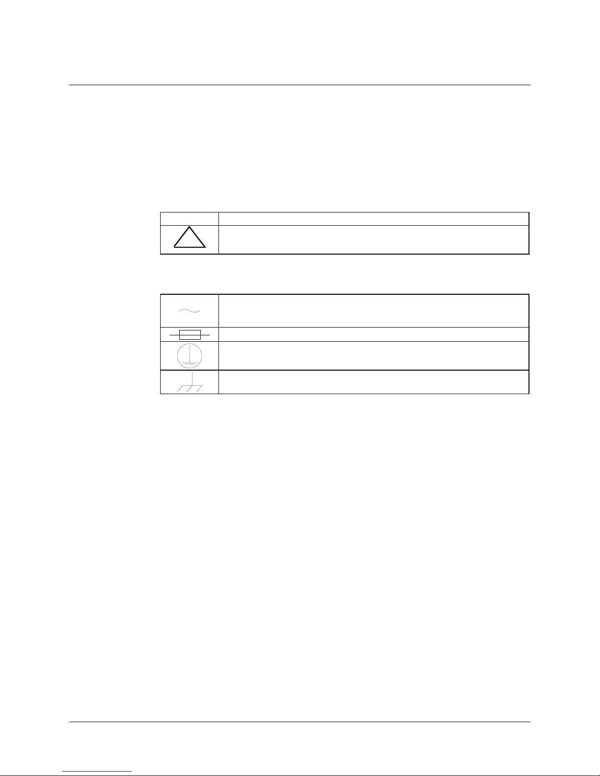
<HAR> Type of power cord required for use in the European Community .
CAUTION: Double-pole/Neutral Fusing
!
International Symbols:
ACHTUNG: Zweipolige bzw. Neutralleiter-Sicherung
Alternating Current.
Fuse.
Safety Ground.
Chassis Ground.
Note:
For additional symbols, refer to “Cautions and Warn ing s” lis ted ea rl ier in t his
preface.
Rev. 0 ix
Page 11

Preface KPA080 Ku-Band Solid-State Power Amplifier
Warranty Policy
This Comtech EFData product is warranted against defects in material and workmanship
for a period of 2 years from the date of shipment. During the warranty period, Comtech
EFData will, at its option, repair or replace products that prove to be defective.
For equipment under warranty, the customer is responsible for freight to Comtech
EFData and all related custom, taxes, tariffs, insurance, etc. Comtech EFData is
responsible for the freight charges
only
for return of the equipment from the factory to
the customer. Comtech EFData will return the equipment by the same method (i.e., Air,
Express, Surface) as the equipment was sent to Comtech EFData.
Limitations of Warranty
The foregoing warranty shall not apply to defects resulting from improper installation or
maintenance, abuse, unauthorized modification, or operation outside of environmental
specifications for the product, or, for damages that occur due to improper repackaging of
equipment for return to Comtech EFData.
No other warranty is expressed or implied. Comtech EFData specifically disclaims the
implied warranties of merchantability and fitness for particular purpose.
Exclusive Remedies
The remedies provided herein are the buyer's sole and exclusive remedies. Comtech
EFData shall not be liable for any direct, indirect, special, incidental, or consequential
damages, whether based on contract, tort, or any other legal theory.
Disclaimer
Comtech EFData has reviewed this manual thoroughly in order that it will be an easy-touse guide to your equipment. All statements, technical information, and
recommendations in this manual and in any guides or related documents are believed
reliable, but the accuracy and completeness thereof are not guaranteed or warranted, and
they are not intended to be, nor should they be understood to be, representations or
warranties concerning the products described. Further, Comtech EFData reserves the
right to make changes in the specifications of the products described in this manual at any
time without notice and without obligation to notify any person of such changes.
If you have any questions regarding your equipment or the information in this manual,
please contact the Comtech EFData Customer Support Department.
x Rev. 0
Page 12

This chapter describes the instructions on the installation, operation and maintenance of
the KPA080-4045-I Ku-Band Solid-State High Power Amplifier (SSPA).
1.1 Overview
The KPA080-4045-I Ku-Band Solid-State High Power Amplifier is designed for use in
communication systems, or in satellite up-link data systems. The SSPA (Figure 1-1)
operates over the RF input frequency range of 14.0 to 14.5 GHZ.
Chapter 1.
INTRODUCTION
1
Rev. 0 1-1
Figure 1-1. KPA080
Page 13
Introduction KPA080 Ku-Band Solid-State Power Amplifier
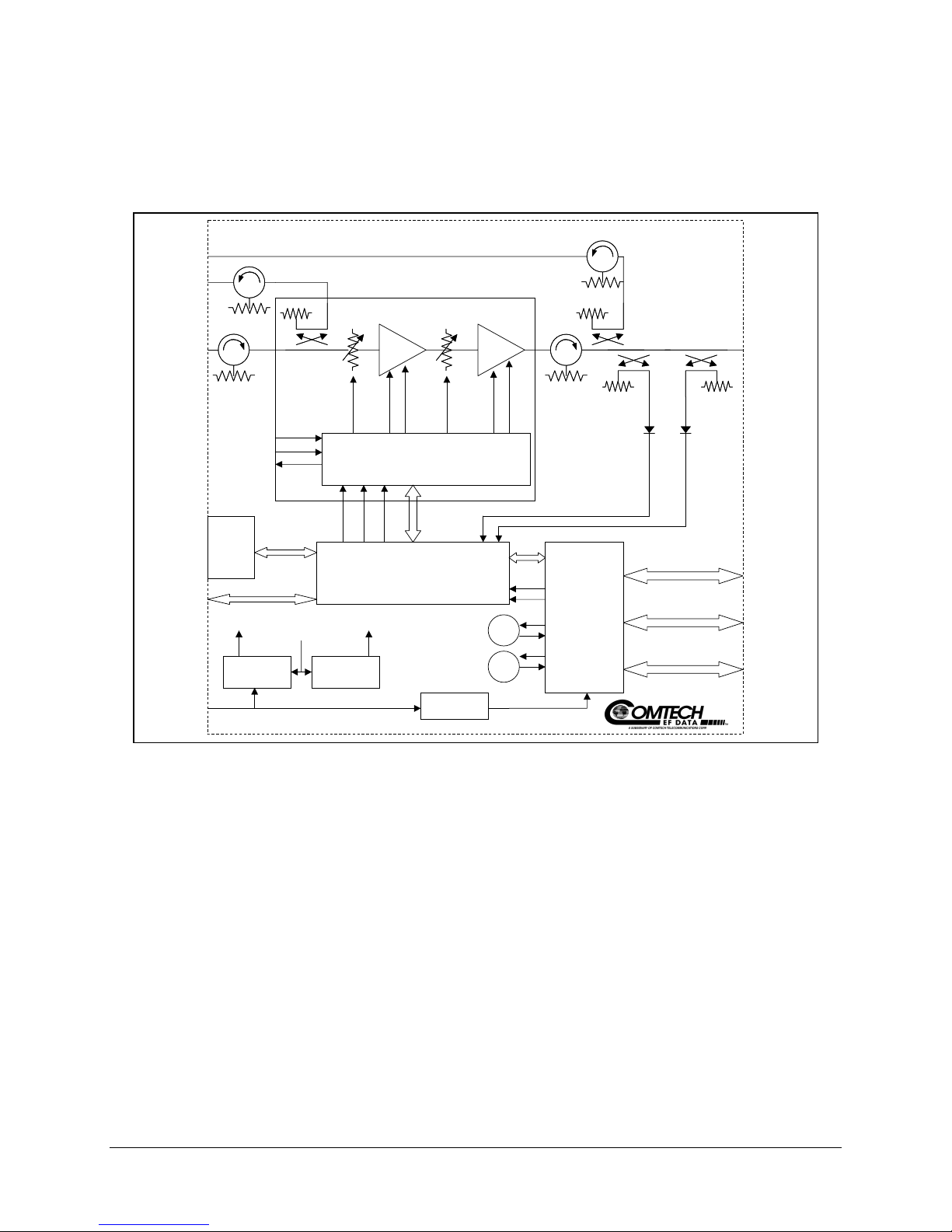
The RF output power is 48.5 dBm minimum at 1 dB compression. A functional block
diagram is shown in Figure 1-2.
KPA 80
OUTPUT
SAMPLE
INPUT
SAMPLE
J9
J8
BLOCK DIAGRAM
RF INPUT
AC
POWER
INPUT
J1
CUST.
GAIN
CTRL
9V #1
9V #2
-5Vdc
Interlock
-5Vdc
Interlock
-5V -12V 12V
PS #2 9Vdc
Keypad
&
Display
J6COM1
9V #1 9V #2
PS #1 9Vdc
J3
-5V -5V9V 9V
POWER CONDITIONING & CONTROL
MONITOR & CONTROL
TEMP.
COMP.
CONTROL
& MONITOR
28Vdc PS
FAN1
FAN2
+12V
-12V
AUX. PS
& SWITCH
CONTROL
OUTPUT
POWER
DETECTOR
REFLECTED
POWER
DETECTOR
RF
J2
OUTPUT
(W/G)
REDUND.
J4
LOOP
DISCRETE
J5
CONTROL
REDUND.
SWITCH
J7
CONTROL
Figure 1-2. Functional Block Diagram
The SSPA is designed to be hard mounted in a standard 19-inch (48 cm) rack or cabinet,
or to be rack mounted using Comtech EFData slide mechanisms provided with the SSPA
to allow it to be serviced without its removal from the rack. Two internally mounted
exhaust fans are mounted on the chassis for cooling. An AC power connector, with an
On/Off switch, is located on the rear on the chassis. A six-foot AC power cord is supplied
with the SSPA.
All operator controls, indicators, and displays for local and remote operation as well as
the RF Input and Output sample test ports are located on the front panel of the SSPA.
Connectors for the external interface connections are located on the rear of the SSPA
chassis.
1-2 Rev. 0
Page 14
KPA080 Ku-Band Solid-State Power Amplifier Introduction
1.2 Functional Description
The SSPA consists of a chassis, power supplies, fan assembly, front panel assembly,
monitor/control processor (MCP) and a Comtech EFData solid-state power amplifier
module. The amplifier is designed using a Comtech EFData low loss combining
technique and an MCP based temperature versus gain compensation.
1.2.1 Front Panel
The front panel contains a User Interface Key-Pad which is used by a local operator to
input commands to the SSPA. The keypad is used to select the configuration for
operating and monitoring the status of the SSPA.
In conjunction with the front panel two line, 24-character, LCD display, the keypad
allows the operator to select one of five configurations. The configuration functions are:
Configuration Menu
•
Monitor Status Menu
•
Currents Faults Menu
•
Stored Faults Menu
•
Utility Functions Menu
•
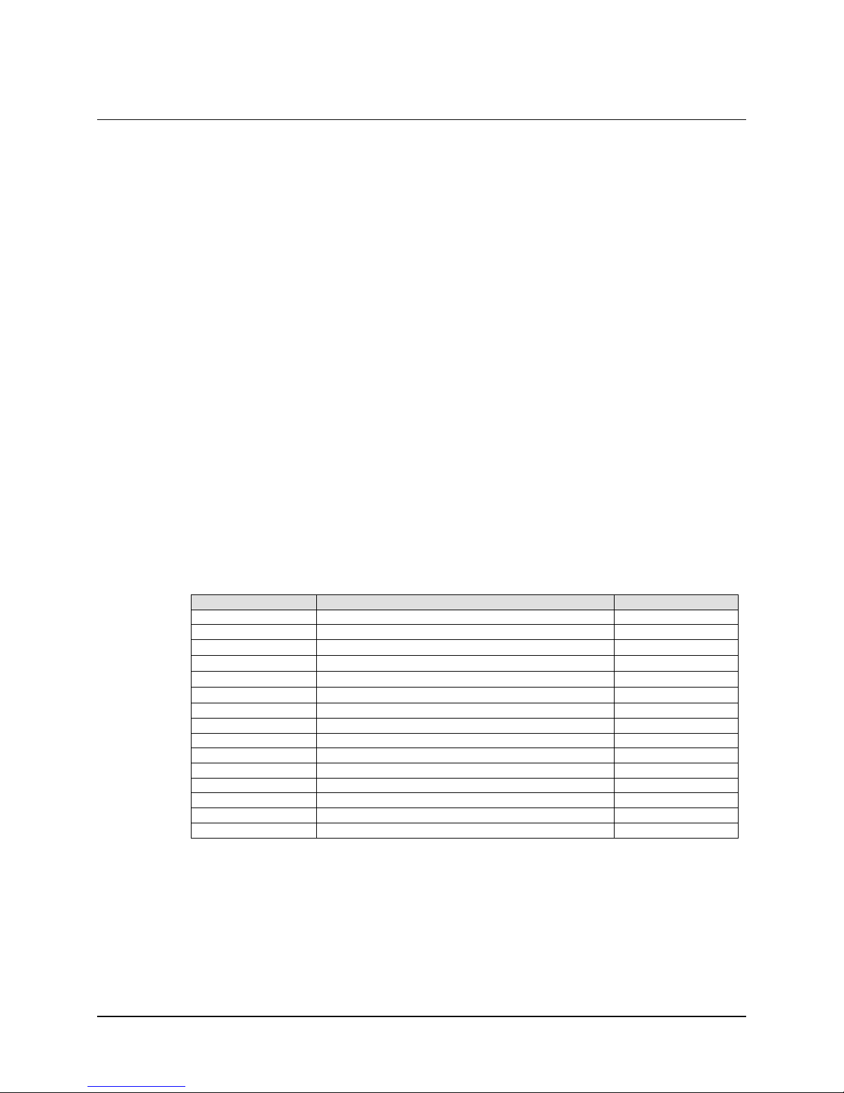
Refer to Table 1-1 for logical function of each keypad entry:
Table 1-1. Operating Functions
Item Function D escription Reference
[ENTER] Enters commands into the converter. ENT
CLR Clears commands and data selected and not entered. CLR
Arrow Key
→
Arrow key
←
Arrow Key
↑
Arrow Key
↓
LCD Display Displays commands and data entered into the keypad.
GREEN Indicator Prime Power is applied when the light is On. POWER ON
YELLOW Indicator Transmit function operating when the light is On. TRANSMIT ON
YELLOW Indicator In REMOTE CONTROL Mode, when the light is ON. REMOTE
YELLOW Indicator Operating On-Line to RX data when the light is On. ON-LINE
RED Indicator Fault condition exists when the light is On. FAULT
RED Indicator Faults stored and logged when the light is On. STORED FAULT
Input Sample Type N connector test point to sample RF input. SAMPLE INPUT
Output Sample Type N connector test point to sample RF output. SAMPLE OUTPUT
Selects functions and the menu operating data.
Selects functions and the menu operating data.
Selects functions and the menu operating data.
Selects functions and the menu operating data.
→
←
↑
↓
Rev. 0 1-3
Page 15

Introduction KPA080 Ku-Band Solid-State Power Amplifier
1.2.2 Front Panel Indicators
There are six LED indicator lights on the front panel which indicate the status of the
SSPA and provide summary fault information. Refer to Table 1-2 for description of the
LED lamps:
Table 1-2. Front Panel Indicators
LED Lamp Condition
Fault Red Indicates that a fault condition exists when the LED light is
On.
Stored Fault Red Indicates that the fault has been logged and stored When the
LED light is On. The fault may, or may not, be active.
Power Status Green Indicates that power is applied to the SSPA when the LED
light is On.
TX ON Yellow Indicates that the transmit function of the SSPA is on when
the LED light is On. The indicator light reflects the actual
condition of the tran smit function.
Online Yellow Indicates that the SSPA is operating on-line to transmit data.
Remote Yellow Indicates that the SSPA is being operated in the remote
control mode where commands and data are transferred via
an EIA-485 (EIA-232 is optional) serial
communications link.
1.2.3 Built-in Redundancy Controller
Each SSPA has the ability to function as a 1+1 or 1+2 redundancy controller in the
backup mode. The optional redundancy configuration is implemented by attaching a
ganged Waveguide/coax transfer switch(es) to input and output connectors of the
amplifiers with a combination coaxial cable and Waveguide kit. When the backup SSPA
is commanded into the controller mode, it monitors the online SSPA(s) for faults. A
faulted online unit may be disconnected and replaced without affecting the online power
amplifier.
1-4 Rev. 0
Page 16
KPA080 Ku-Band Solid-State Power Amplifier Introduction
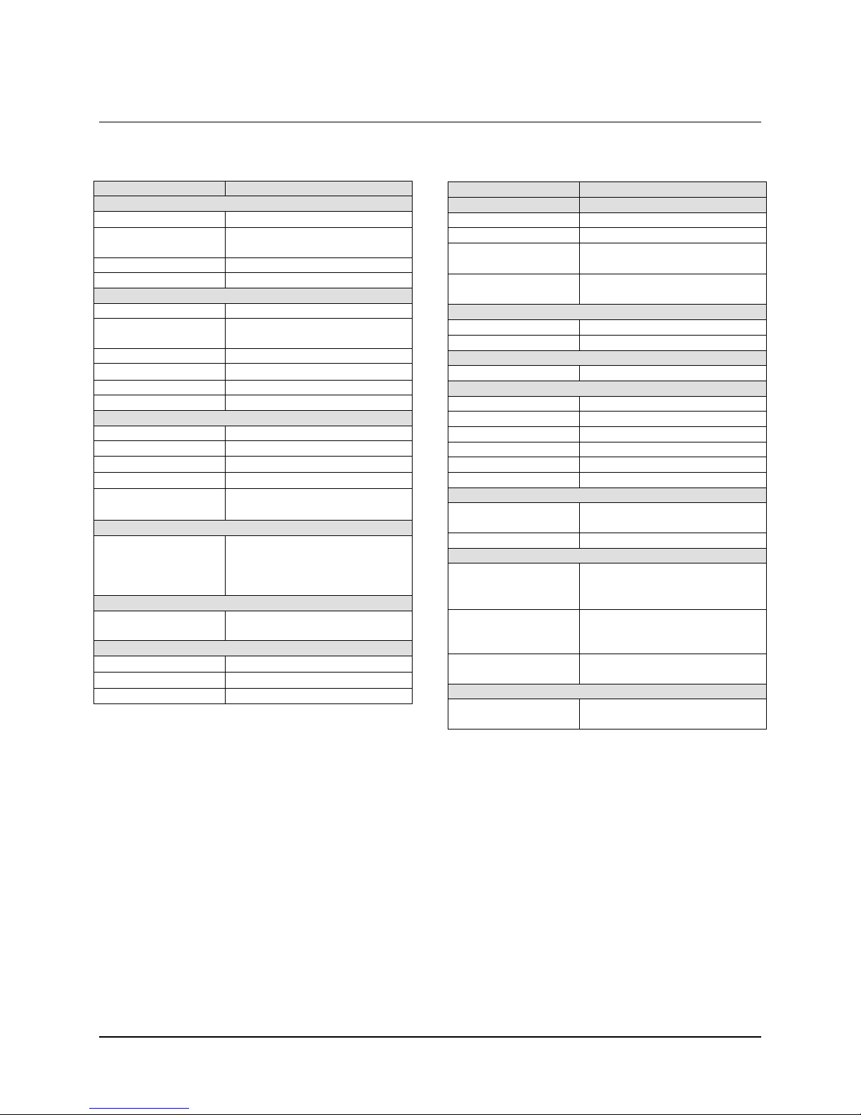
1.3 Specifications
Parameters Specifications
Input
Impedance
Noise Figure 10 dB Typical, 15 dB max at max
VSWR 1.25: 1 maximum
Connector SMA Female
Frequency 14.0 to 14.5 GHz
Power 48.5 dBm minimum at 1 dB
Mute 60 dB
Impedance
VSWR 1.25:1 maximum
Connector WR75G Waveguide
Linear 65 dB minimum, 68 dB Typical
Adjust 20 dB in 0.25 dB steps
Full Band
Per 40 MHz
0 to +50°C (32 to
122°F)
Third Order Intermodulat ion
Products -30 dBc Typical, -25 dBc
Output 2.0 degrees typical, 3.0 max at
Group Delay (per 40 MHz)
Linear
Parabolic
Ripple 1.0 ns Peak-t o-Peak
50Ω
gain
Output
Compression
50Ω
Gain
0.75 dB
±
-0.25 dB
±
0.50 dB at center frequency
±
1.00 dB full band
±
maximum
at 3 dB total backoff
(two tones, ∆F = 1 MHz)
AM to PM Conversion
rated output
0.03 ns/MHz
±
0.003 ns/MHz2
±
Parameters Specifications
Front Panel
Display 20 x 2 LCD
Data Entry Cursor Control Keypad
Output Sample
Input Sample
Remote Control
COM Port EIA-232 or EIA-485
Protocol ASCII
Summary Fault Form C
Power On Green
Fault Red
Stored Fault Red
TX On Yellow
Online Yellow
Remote Yellow
Envelop 8.75H x 19W x 24D inches
Weight 75 lbs (34 kg)
Temperature
Operating
Storage
Humidity
Operating
Storage
Shock Normal Commercial
Power Requirements
VAC 180 to 270 VAC, 47 to 63 Hz
Type N (f), 50Ω, –40 dBc
nominal
Type N (f), 50Ω, –20 dBc
nominal
Alarms
LED
Mechanical
(22.22H x 48.26W x 60.96D cm)
Environmental
0 to 50°C (32 to 122°F)
–40 to 70°C (–40 to 158°F)
10 to 95% Noncondensing
0 to 100% Noncondensing
Shipping and Handling
1100W nominal
Rev. 0 1-5
Page 17

This page is intentionally blank.
Rev. 0 1-6
Page 18

This chapter describes the instructions for unpacking and installing the KPA080-4045-I
Ku-Band Solid State High Power Amplifier
2.1 Unpacking
Perform a receiving inspection as follows:
Inspect the shipping container for damage. The shipping container and packing
•
materials should be retained for possible reshipment.
Check to determine that all parts, materials and documentation have been shipped
•
with the SSPA. The SSPA should be inspected for possible damage, and then tested
for proper operation.
If the shipment exhibits any of the following, contact Comtech EFData Customer
•
Support:
Incomplete
♦
Mechanical damage
♦
Inoperable
♦
If there is damage to the shipping container, notify the carrier. Retain all shipping
materials for inspection by the carrier.
Chapter 2.
INSTALLATION
2
Rev. 0 2-1
Page 19

Installation KPA080 Ku-Band Solid-State Power Amplifier
2.2 Installation
The SSPA is designed for installation to mount in a standard 19-inch (48 cm) rack
cabinet or enclosure. The SSPA chassis requires 8.75 inches (22 cm) of panel height
space.
Adequate air ventilation should be provided to the rack mounted equipment.
air is taken in through the front panel and exhausted out the rear panel.
Locate the SSPA so the input and output airflow paths are not obstructed or
restricted.
This will minimize the amplifier operating temperature.
If the SSPA is to be mounted on slides, the slides must be the Comtech
•
EFData rack slides provided with the SSPA. Proceed as follows:
!" Mount the slides on the sides of the SSPA chassis with the provided
mounting hardware.
!" Install the slide rails on the rack cabinet enclosure.
!" Secure the SSPA to the cabinet with four screws inserted through the
SSPA front panel slotted holes.
Cool
2.2.1 Prime Power Connection
The On/Off prime power switch is located on the rear of the chassis adjacent to the prime
power input connector. The circuit breaker is ra ted for 30 Amps.
The detachable power cord mates with the AC Prime power receptacle on the rear of the
SSPA chassis.
A power cord for connection to 180 to 270 VAC, 47 to 63 Hz, power sources is provided
with the SSPA.
2-2 Rev. 0
Page 20

KPA080 Ku-Band Solid-State Power Amplifier Installation
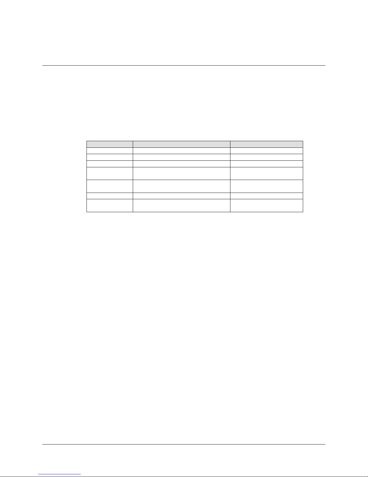
2.2.2 Cable Connections
The cable signal functions are shown in Table 2-1.
Table 2-1. Cable Connections
Connector Function
J1 SSPA RF Input (RF). Mating connector: Type SMA Female
J2 SSPA RF Output (RF). Mating connector: WR75G
J3 AC Prime Power (Cord provided with SSPA)
J4 Redundant Loop Int erface (for use in redundant configurations)
J5 Customer Discrete Control
J6 COM 1: Serial Communications Interface, EIA-232 or EIA-485
communications links
Mating connector: Type DB9M
J7 Waveguide Switch Interface (for use in redundant configurations)
2.2.3 Optional: Redundancy Kit Installation
Comtech EFData SSPAs are easily configured for redundant systems by using one of the
optional Redundant Cable Kits. These kits include all the necessary controls, semi-rigid,
and waveguide cabling, and appropriate waveguide/coax switches and terminations.
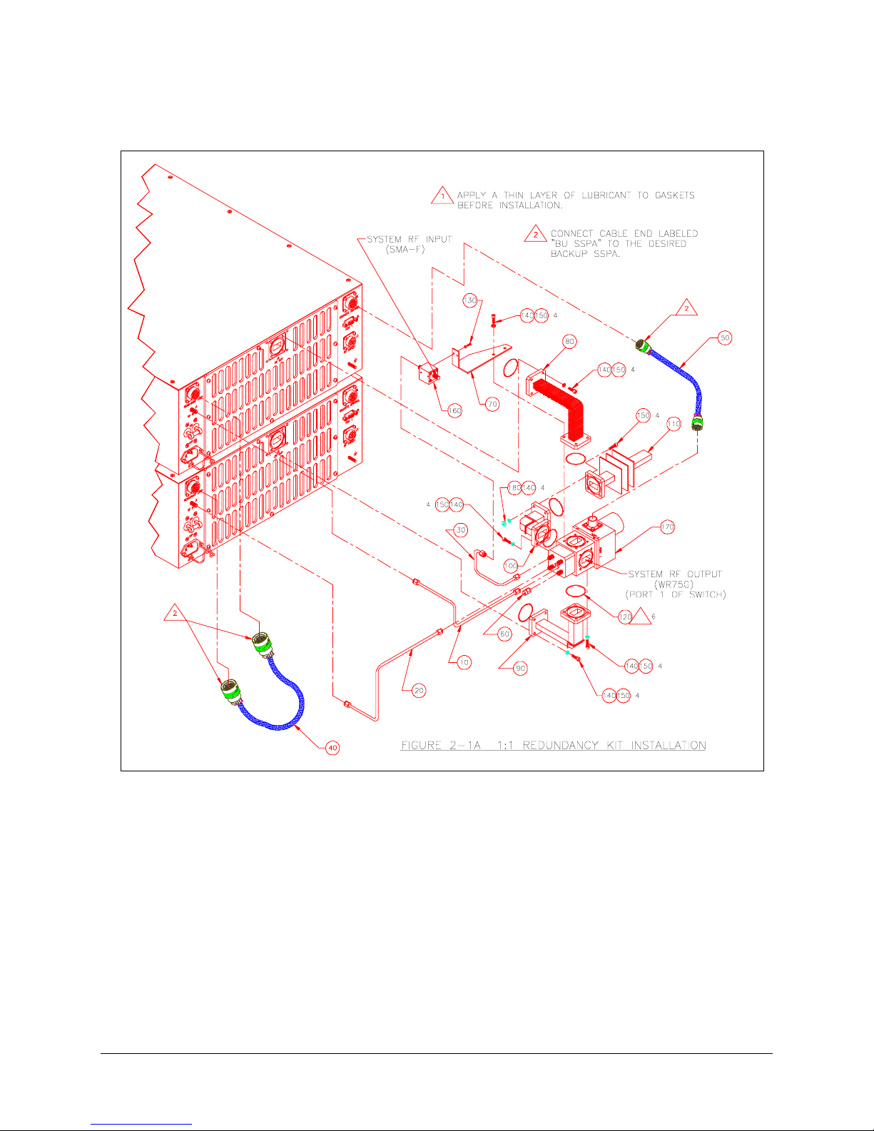
Figure 2-1 shows the typical 1:1 installation and Table 2-2 shows the associated parts list.
The primary and backup SSPAs shall be installed next to each other in a standard 19-inch
(48 cm) equipment rack. Because of the configuration of the dual WG-Coax Switch, the
upper SSPA will always act as the backup.
Rev. 0 2-3
Page 21
Installation KPA080 Ku-Band Solid-State Power Amplifier
Figure 2-1. Redundancy Installation
1
2-4 Rev. 0
Page 22

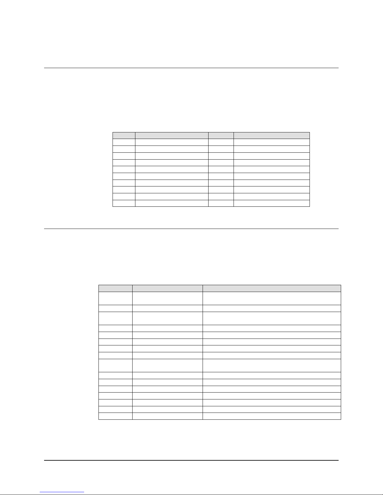
KPA080 Ku-Band Solid-State Power Amplifier Installation
Table 2-2. Redundancy Kit
Item No. Part No. QTY Nomenclature
AS/0435 KPA080 SSPA
10 CA/RF0075 1 Cable, SW P3 to Upper J1, Red Kit, 1:1
20 CA/RF0076 1 Cable, SW P2 to Lower J1, Red Kit, 1:1
30 CA/RF0065 1 Cable, SW P4 to Isolator, Red Kit. 1:1
40 CA/WR0006 1 Cable, Redundant Loop
50 CA/WR0007 1 Cable, Waveguide Switch to B-UP J7
60 CN/CX2001-6501-00 1 Connector, OSM, SMS, Plug Termination
70 FP/BR0042 1 Bracket, Mounting, Isolator, Red Kit 1:1
80 FP/WG0045 1 Waveguide, WR75, Upper, 90, Red Kit 1:1
90 FP/WG0046 1 Waveguide, WR75, Lower, 90, Red Kit 1:1
100 FP/WG0024 1 Waveguide, WR75, Elbow, 90, Red Kit 1:1
110 FP/WG0025 1 Waveguide, WR75, Termination, 150W, Red Kit, 1:1
120 GA/GSKT,WR75,FULL 7 Gasket, WR75, Full THK
130 HW/080/3/16PHMS 2 0-80 x 3/16 PHM Screw, SS
140 HW/632X3/8SHCS-B 32 Screw, 6-32 x 3/8 SHCS, Black
150 HW/06LOCK 32 #6 Lock Washer, SS
160 RF/ISHF037306-001 1 RF-ISO, 13-16G, SMS-FF
170 SW/WG-754A0 1 SW-WR75, O-Ring, Dual WGSMA
180 XX/P-SUPER O-LUBE AR Parker Super, O-Lube, 2 oz
Perform the installation as follows:
1. Assemble the waveguide load and bend to the proper port of the switch.
Note:
Remember to install a gasket between each waveguide interface (refer to
Figure 2-1).
2. Attach the rigid lower waveguide arm, using the supplied screws. The switch
should be installed with “Port 1” facing outward.
3. The upper Waveguide (flexible arm) along with the isolator bracket should
be installed next.
4. Complete the installation by attaching the coaxial cables, coaxial load, and
control cables.
5. Note that the installation of the control cables determines which unit will
function as the backup SSPA. Due to the nature of the dual WG-coax switch,
this will always be the upper unit. Therefore, the end of the redundant loop
cable (40, Figure 2-1) labeled “BU SSPA,” should be connected to J4 of the
upper (back-up) unit.
6. The appropriate end of the control cable attaching to the Waveguide switch
(50) should also be attached to the backup unit (J7).
Redundancy kits with all the cabling and switches for a 1:2 configuration also are
available, and are usually designed to a particular customer’s specifications. Contact
Comtech EFData for 1:2 redundancy kits and installati on diagram s.
Rev. 0 2-5
Page 23
Installation KPA080 Ku-Band Solid-State Power Amplifier
2.3 External Connections
2.3.1 Rear Panel Connections
Refer to Table 2-3 for a list of the connectors on the rear panel.
Table 2-3. Rear Panel Connectors
Connector Description Mating Co nnecting
J1 SSPA RF Input (RF IN) Type SMA (f)
J2 SSPA RF Output (RF OUTPUT) WR75G
J3 AC Prime Power Input (AC IN)
J4 Redundant Loop Interface
(REDUND LOOP)
J5 Customer Discrete Control
(DISCRETE CONTROL)
J6 COM1 Port (EIA-232/EIA-485) (COM1) DB9M
J7 Waveguide Switch Interface
(RF SWITCH)
MS3116F14-19P
MS 3116F14-19P
MS3116F12-10P
2-6 Rev. 0
Page 24
KPA080 Ku-Band Solid-State Power Amplifier Installation
2.3.1.1 Redundant Loop Interface, Connector J4
The Redundant Loop Interface connector J4 is a 19-pin circular connector, type
MS3112E14-19S. The pin-out specification is contained in Table 2-4. This connector is
used only in redundant configurations.
Table 2-4. Redundant Loop Interface, Connector J4
Pin # Description Pin # Description
A Loop In 1 L Sumflt 2 NO
B ADDR 2 M SumFlt 2 Common
C Loop In 2 N Local Loop Out
D Loop Out 2 P Sumflt 1 NO
E ADDR Common R Sumflt 1 Common
F ADDR 1 S Local Sumflt Common
G Loop Out 1 T Local Sumflt NO
H HSB +RX/TX U No Connect
J HSB – RX/TX V No Connect
K Local Loop In
2.3.1.2 Customer Discrete Control, Connector J5
The Customer Discrete Control connector J5 is a 19-pin circular connector, type
MS3112E14-19S. The pin-out specification is contained in Table 2-5.
Table 2-5. Customer Discrete Control, Connector J5
Pin # Signal Name Description
A Auto Select Momentary short to pin F to force entire subsystem to
Auto Mode.
B BU-1 Command Momentary short to pin F to force backup of SSPA #1.
C Priority 2 Sel Momentary short to pin F to set SSPA #2 as HIGH
priority.
D BU-2 Command Momentary short to pin F to force backup of SSPA #2.
E 2 Online NO Tied to pin G when Online, all other conditions OPEN.
F Remote Common Control – Remote Common.
G Online Common Online Status Common.
H BU Online NO Tied t o pin G when Online, all other condi tions OPEN.
J Manual Select Momentary short to pin F to force entire subsystem to
Manual Mode.
K 1 Online NO Tied to pin G when Online, all other conditions OPEN.
L 2 Fault NO Tied to pin N when Faulted, all other conditions OPEN.
M Priority 1 SEL Momentary short to pin F to set SSPA #1 as High priority.
N Fault Common Fault Status Common.
P BU Fault NO Open when faulted, else tied to Pin N.
R BU Offline CMD Momentary short to pin F to force backup SSPA Offline.
S 1 Fault NO Open when faulted, else tied to Pin N.
Rev. 0 2-7
Page 25

Installation KPA080 Ku-Band Solid-State Power Amplifier
2.3.1.3 EIA-232/EIA-485 Interface, Connector J6
The EIA-232/EIA-485 Interface connector J6 is a 9-pin D type DB9F connector socket.
The pin-out specifications are contained in Table 2-6. The mating connector is a DB9M.
Table 2-6. EIA-232/EIA-485 Interface, Connector J6
Pin # EIA-232 EIA-485 4-W i r e EIA-485 2-Wire
1 No Connect Ground (GND) Ground (GND)
2 Transmit Data (TD) No Connect No Connect
3 Receive Data (RD) No Connect No Connect
4 No Connect +TX Sign al +RX/TX Signal
5 Ground (GND) -TX Signal -RX/TX Signal
6 Unit Ready – always high
(DSR)
7 Request to Send. Looped to
CTS (RTS)
8 Clear to Send (CTS) +RX Signal +RX/TX Signal
9 No Connect -RX Signal -RX/TX Signal
No Connect No Connect
No Connect No Connect
2.3.1.4 Waveguide Switch Interface, Connector J7
The waveguide switch interface connector J7 is a 10-pin circular connector, type
MS3112E12-10S. The pin-out specification is contained in Table 2-7. This connector is
used only in redundant configurations.
Table 2-7. Waveguide Switch Interface, Connector J7
Pin # Description
A Command BU-1
B Command Common
C Command 1 Online
D IND 1 Online
E IND Common
F IND BU Online
G Command BU-2
H Command BU-2
J IND 2 Online
K No Connect
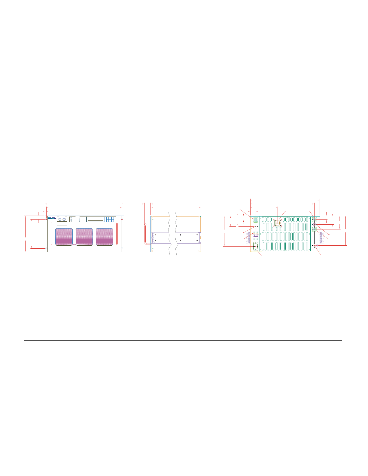
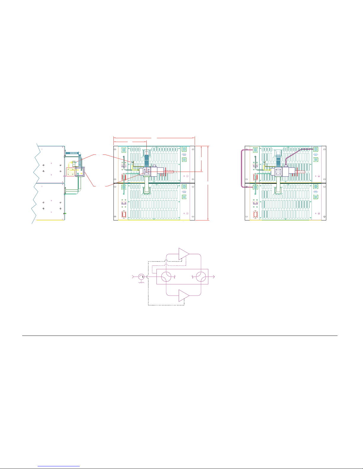
2.4 Dimensional and Outline Diagrams
Refer to Figure 2-2 for the Dimensional Diagram (all measurements shown in inches) and
to Figure 2-3 for the Redundancy Outline Diagram.
2-8 Rev. 0
Page 26
KPA080 Ku-Band Solid-State Power Amplifier Installation
Rev. 0 2-9
Figure 2-2. Dimensional Diagram (inches)
REMOTE
Tx ON
8.72
7.00
OUTPUT
KPA-080
SSPA
INPUT
STORED FAULT
FAULT
POWER ON
18.25
.86
.38
SAMPLE
ON LINE
19.00 1.50
24.00
14-19S
.92
RF OUTPUT
(WR-75G)
RF OUT
SMA (F)
SWITCH
1.66
7.28
2.50
AC ENTRY
AC IN
J3
O
I
RF IN
REDUNDANT LOOP
J4
J1
GROUND LUG
DE09 (S)
10-10S
RF SWITCH
J7
DISCRETE CONTROL
COM1
J6
J5
2.00
7.06
3.19
6.65
1.31
J2
15.44
.75
16.75
14-19S
Page 27
Installation KPA080 Ku-Band Solid-State Power Amplifier
2-10 Rev. 0
Figure 2-3. Redundancy Outline Diagram
BLOCK DIAGRAM
RF IN
4
COAX
RF OUT
SSPA
#1
3
2
1
SWITCH
2
4
31
WG
BU
SSPA
DISCRETE CON TROL
COM1
RF SWITCH
COM1
DISCRETE CON TROL
RF SWITCH
RF OUT
REDUNDANT LOOP
REDUNDANT LOOP
RF OUT
AC IN
J3
O
I
RF IN
J1
RF IN
1
2
3
4
AC IN
J3
RF IN
J4
J1
PORT 1
19.0
7.8
J2
RF OUT
J7
J6
J5
17.5
J7
J6
J5
6.1
AC IN
J3
O
REDUNDANT LOOP
I
RF IN
J1
AC IN
J3
REDUNDANT LOOP
RF IN
J4
J1
PORT 1
J2
RF SWITCH
J7
DISCRETE CON TROL
COM1
J6
J5
RF SWITCH
J7
DISCRETE CON TROL
COM1
J6
J5
(CONTROL CABLES NOT SHOWN IN THIS VIEW)
Page 28

This chapter describes the instructions for operating the KPA080-4045-I Ku-Band Solid
State High Power Amplifier.
3.1 General
The front panel of the SSPA has a keypad for the operator input commands, an LCD
Display, LED status indicators, and connector test sample ports to monitor the RF input
and output signals.
3.1.1 Switching On
Chapter 3.
OPERATION
3
Prior to positioning the Prime Power Switch to On, perform the following:
1. Check to ensure that the installation is complete.
2. Verify that the SSPA is connected to the proper prime power source, RF input,
and RF output.
3. Switch the On/Off Prime Power Switch on the rear panel to On.
4. Verify that the cooling fans are operating, and that the POWER ON LED
STATUS indicator light is On.
Rev. 0 3-1
Page 29

Operation KPA080 Ku-Band Solid-State Power Amplifier
5. After the PRIME POWER is switched on, the STATUS indicators should be as
follows:
POWER ON
TRANSMIT
REMOTE
ON LINE
FAULT
STORED FAULT
ON
OFF
ON
ON
OFF
OFF
After the AC power is switched on and prior to pressing the buttons on the keypad, the
LCD display message should read as follows:
KPA080-4045-I
SW VER X.XX SN4045 XXXX
3-2 Rev. 0
Page 30

KPA080 Ku-Band Solid-State Power Amplifier Operation
3.2 Operation
Local control of the SSPA is controlled by operator input commands initiated through the
six button keypad on the front panel. The keypad is the local operator’s interface to
control, configure and monitor the status of the SSPA. Operator inputs and commands
entered into the keypad are displayed by the front panel, 24-character, 2-line LCD
display.
There are five operating functions:
Configuration
•
Monitor Status
•
Current Faults
•
Stored Faults
•
Utility Functions
•
Flow charts for selecting the commands, operating menus, and data inputs are shown in
Figure 3-1 through Figure 3-6.
Rev. 0 3-3
Page 31
Operation KPA080 Ku-Band Solid-State Power Amplifier
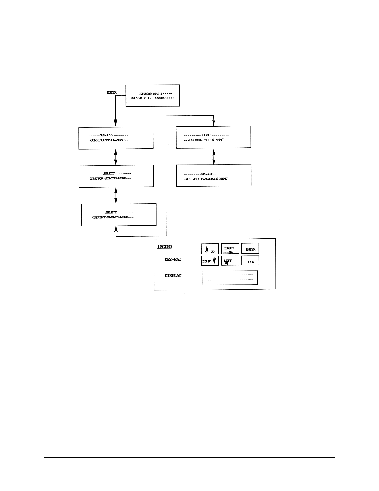
Figure 3-1. SSPA Operating Command Functions
3-4 Rev. 0
Page 32

KPA080 Ku-Band Solid-State Power Amplifier Operation
3.2.1 SSPA Commands
The SSPA commands are presented in a tree structured menu format designed for access
and execution of all control functions and to prevent the execution of an invalid entry by
the operator. When the prime power is turned On, the LCD display will contain a
message indicating the SSPA model number and the version number of the firmware
installed in the SSPA.
To select a Command Function press the <ENT> button on the keypad. The LCD display
will indicate:
SELECT
CONFIGURATION MENU
This will provide the local operator access to the Command Function Menus, which is the
top level structure to start the selection of Command Function Menus to input into the
SSPA.
To sequence to the next Command Function Menu press a ↓ or ↑ arrow button on the
keypad. The SSPA will step to the next Command Function Menu each time a ↓ or ↑
arrow button is pressed. The current Command Function Menu will be displayed on the
LCD display. The Command Function Menus are shown in Figure 3-1.
To select a specific Command Function Menu press the <ENT> keypad button. If a
function is selected in error, press the clear <CLR> button which will return the SSPA to
the main command menus to allow the selection of another function. Any one of the five
Command Function Menus can be selected using this procedure.
Once a Command Function has been selected, use the → or ← arrow key-pad buttons to
sequence through the Operating Mode Commands. Each of the modes will be displayed
on the LCD display. A specific operating mode is selected by pressing the <ENT>
button. If a mode is selected in error, press the clear <CLR> button which will return the
SSPA to the operating menus to allow the selection of another mode.
When an operating mode is selected, a parameter or a digit within the parameter will be
flashing on the LCD display. Use the → and ← arrows buttons to sequence through the
parameters or digits to select the next parameter or digit. A specific parameter or value is
selected by pressing the <ENT> button. If a parameter or value is selected in error, press
the <CLR> button which will return the SSPA to the original parameter or value to allow
another selection.
After selecting a parameter or digit, use the ↓ or ↑ arrow buttons to select the next
parameter, or to increment or decrement the value of a digit. A specific new parameter or
new value is selected by pressing the <ENT> button. If a parameter or value is selected in
error, press the <CLR> button which will return the SSPA to the original parameter or
value to allow another selection.
Each time the clear ("CLR") button is pressed, the SSPA will return to the menu level
prior to the last "ENT" command.
Rev. 0 3-5
Page 33

Operation KPA080 Ku-Band Solid-State Power Amplifier
This page is intentionally left blank.
3-6 Rev. 0
Page 34

KPA080 Ku-Band Solid-State Power Amplifier Operation
Figure 3-2A. Configuration Menu Commands (Single Configuration)
Rev. 0 3-7
Page 35

Operation KPA080 Ku-Band Solid-State Power Amplifier
Figure 3-2B. Configuration Menu Commands (Redundancy Mode)
3-8 Rev. 0
Page 36

KPA080 Ku-Band Solid-State Power Amplifier Operation
3.2.2 Configuration Menu
The Configuration Functions (Figure 3-2A or Figure 3-2B)are as follows:
Attenuation:
Amplifier
Mute
Entry Mode
Fault Recovery:
Redundancy Configuration
Priority SSPA
Operating Mode
Gain OFFSET/ Forced Backup
Activate Backup:
Attenuation (ATTN): Input and displays the SSPA attenuation setting
which is selected between 0.00 to 20.00 in 0.25 dB steps. The default
setting is 10.00 dB.
Amplifier: Control supply voltage to RF FETS. The default mode is
ON.
Mute: Provide SSPA mute control. The default is OFF.
Mode: The entry mode is Local or Remote. The default is Local.
Fault Recovery is Manual or Auto. The default is Auto.
This menu window provides indication of the operating
mode (i.e. stand alone or redundancy).
Provides selection of priority SSPA in 1:2 redundancy systems.
Always 1 in 1:1 redundancy systems.
Note:
Window not displayed when redundancy is Off.
Provides selection of either AUTO or MANUAL operating mode in
redundancy systems.
Note:
Window not displayed when redundancy is Off.
Gain offset: Provides for ± 7.0 dB offset to be entered for individual
SSPA’s in redundancy systems for Gain Equalization.
Note:
Window not displayed when redundancy is Off.
Provides ONLINE/OFFLINE control when manual mode is selected.
Note:
Window not displayed when redundancy is Off.
Rev. 0 3-9
Page 37

Operation KPA080 Ku-Band Solid-State Power Amplifier
UP
UPUP
SELECT
---------
---------
--
--
SELECT
---------
MONITOR-STATUS-MENU
MONITOR-STATUS-MENU
ENTER
ENTER
---------
---
---
DOWN
DOWNDOWN
-RF-
-RF-
FET
----Q3-=-
FET
----Q4-=-
X.X-AMPS
X.X-AMPS
+12V=+12.2
+12V=+12.2
VCC=4.9
VCC=4.9
--
--
28-VDC-PS-=-27.9--
28-VDC-PS-=-27.9--
----
----
9VPS1=9.1 9VPS2=9.0
9VPS1=9.1 9VPS2=9.0
AMPLIFIER-TEMP=+44C
AMPLIFIER-TEMP=+44C
--
--
------------------------
------------------------
FORWARD-RF-PWR:-53.0-DBM
FORWARD-RF-PWR:-53.0-DBM
REVERSE-RF-PWR:-<26.2-DBM
REVERSE-RF-PWR:-<26.2-DBM
FET
FET
--RF-
--RF-
FET
FET
--RF-
--RF-
-12V=-12.0
-12V=-12.0
----
----
-5V=-4.9
-5V=-4.9
-----
-----
----Q1-=-
----Q1-=-
----Q2-=-
----Q2-=-
XXXmA
XXXmA
XXXmA
XXXmA
---
---
--
--
--
--
--
--
--
--
-RF-
-RF-
-RF-
-RF-
-RF-
-RF-
-RF-
-RF-
-RF-
-RF-
-RF-
-RF-
-RF-
-RF-
FET
FET
----Q5-=-
----Q5-=-
FET
FET
----Q6-=-
----Q6-=-
FET
FET
----QX-=-
----QX-=-
FET
FET
----QX-=-
----QX-=-
FET
FET
FET
----
----
----
FET
FET
FET
----
----
----
LEGEND
LEGEND
KEY-PAD
KEY-PAD
DISPLAY
DISPLAY
X.X-AMPS
X.X-AMPS
X.X-AMPS
X.X-AMPS
X.X-AMPS
X.X-AMPS
X.X-AMPS
X.X-AMPS
Q26=-X.X-AMPS
Q26=-X.X-AMPS
Q26=-X.X-AMPS
Q27=-X.X-AMPS
Q27=-X.X-AMPS
Q27=-X.X-AMPS
DOWN
DOWN
DOWNDOWN
------------------------
------------------------
------------------------
------------------------
------------------------
------------------------
Figure 3-3. Monitor Status Menu Commands
ENTER
ENTER
ENTERENTER
RIGHT
RIGHT
RIGHTRIGHT
UP
UP
UPUP
LEFT
LEFT
LEFTLEFT
CLR
CLR
CLRCLR
3-10 Rev. 0
Page 38

KPA080 Ku-Band Solid-State Power Amplifier Operation
3.2.3 Monitor Status Menu
Monitors and displays the status (Figure 3-3) of:
All SSPA power supplies.
•
SSPA internal temperature.
•
RF output power level.
•
RF FET currents (Q1 through Q27).
•
Rev. 0 3-11
Page 39

Operation KPA080 Ku-Band Solid-State Power Amplifier
UP
UP
UPUP
SELECT
SELECT
ENTER
ENTER
ENTER
SELECT
---------
---------
---------
---
---
---
DOWN
DOWN
DOWNDOWN
---------
---------
---------
CURRENT-FAULTS-MENU
CURRENT-FAULTS-MENU
CURRENT-FAULTS-MENU
--
--
--
POWER-FAULTS:
POWER-FAULTS:
POWER-FAULTS:
12V=OK--VCC=OK---5V=OK
12V=OK--VCC=OK---5V=OK
12V=OK--VCC=OK---5V=OK
-
-
-
---28-VDC-PS-=-OK---
---28-VDC-PS-=-OK---
---28-VDC-PS-=-OK---
--
--
--
9VPS1=OK---9VPS2=OK--
9VPS1=OK---9VPS2=OK--
9VPS1=OK---9VPS2=OK--
---
---
---
AMPLIFIER-TEMP-=-OK
AMPLIFIER-TEMP-=-OK
AMPLIFIER-TEMP-=-OK
---
---
---
FAN-1-=-OK--FAN-2-=-OK
FAN-1-=-OK--FAN-2-=-OK
FAN-1-=-OK--FAN-2-=-OK
-
-
-
M&C-PROCESSORS-=-OK
M&C-PROCESSORS-=-OK
M&C-PROCESSORS-=-OK
M&C-PROCESSORS-=-OK
--
--
--
--
------------------------
------------------------
------------------------
------------------------
----
----
----
+12V=OK
+12V=OK
+12V=OK
--
--
--
--
--
--
---
---
---
---
Figure 3-4. Current Faults Menu Commands
-
-
-
LEGEND
LEGEND
-
-
-
LEGEND
KEY-PAD
KEY-PAD
KEY-PAD
DISPLAY
DISPLAY
DISPLAY
ENTER
ENTER
ENTER
RIGHT
RIGHT
RIGHT
RIGHTRIGHT
UP
UP
UP
UPUP
DOWN
DOWN
DOWN
DOWNDOWN
------------------------
------------------------
------------------------
------------------------
------------------------
------------------------
------------------------
------------------------
LEFT
LEFT
LEFT
LEFTLEFT
ENTERENTER
CLR
CLR
CLR
CLRCLR
3-12 Rev. 0
Page 40

KPA080 Ku-Band Solid-State Power Amplifier Operation
3.2.4 Current Faults Menu
Displays the status of the current fau lt cond it ions. T he LCD display will indic ate "F T"
when a fault condition exists. The display will indicate "OK" when a fault has not
occurred.
3.2.4.1 Power Faults
Displays the DC voltage power supply faults (Figure 3-4). The DC voltages displayed
are:
+12 VDC
•
-12 VDC
•
VCC
•
-5 VDC
•
• +28 VDC
• +9 VDC, PS1/PS2
3.2.4.2 SSPA Over Temperature Fault
Note:
A temperature fault is indicated if the unit is ≤ -20°C (≤ 4°F) or ≥ 85°C (≥ 185°F).
This creates a summary fault and will cause the unit to mute itself and switchover to the
backup unit. However, the 9V supply to the FET transistors will remain on until the unit
reaches the thermal shutdown temp erature of ≥ 90°C (194°F). For protection reasons, the
unit will shutdown the 9V supply to the power transistors at temperatures ≥ 90°C
(≥ 194°F).
Displays an SSPA temperature fault condition.
3.2.4.3 Fan Fault
Displays status of Fan #1 and Fan #2.
Rev. 0 3-13
Page 41

Operation KPA080 Ku-Band Solid-State Power Amplifier
Figure 3-5. Stored Faults Menu Commands
3-14 Rev. 0
Page 42

KPA080 Ku-Band Solid-State Power Amplifier Operation
3.2.5 Stored Faults Menu
The SSPA displays a total of 100 faults with a date and time stamped and stored in
memory as they occur. The stored faults (Figure 3-5) remain in memory until a clear
command is entered.
Total Stored Faults
Clear All Stored Faults
Display Stored Fault
Displayed the total number of faults stored. The most recent fault stored is
displayed on the LCD display.
Input command to clear all faults. The command is YES or NO which is
displayed on the LCD display.
The local operator can sequence through the stored faults st art ing with the most
recent fault. The Fault nu mber, time, description and date is di splayed on the
LCD disp lay.
Rev. 0 3-15
Page 43

Operation KPA080 Ku-Band Solid-State Power Amplifier
UP
UP
UPUP
SELECT
SELECT
ENTER
ENTER
ENTER
SELECT
---------
---------
---------
---
---
---
DOWN
DOWN
DOWNDOWN
FORWARD -RF-POWER-MONITOR
FORWARD -RF-POWER-MONITOR
FORWARD -RF-POWER-MONITOR
----OFFSET-=-+0.0dBm----
----OFFSET-=-+0.0dBm----
----OFFSET-=-+0.0dBm----
REVERSE-RF-POWER-MONITOR
REVERSE-RF-POWER-MONITOR
REVERSE-RF-POWER-MONITOR
----OFFSET-=-+0.0dBm----
----OFFSET-=-+0.0dBm----
----OFFSET-=-+0.0dBm----
--------LAMP-TEST-------
--------LAMP-TEST-------
--------LAMP-TEST-------
----------OFF-----------
----------OFF-----------
----------OFF-----------
---------
---------
---------
UTILITY-FUNCTIONS-MENU
UTILITY-FUNCTIONS-MENU
UTILITY-FUNCTIONS-MENU
--
--
--
----TIME:- 10:20:05AM----
----TIME:- 10:20:05AM----
----TIME:- 10:20:05AM----
-----DATE--09/15/94------
-----DATE--09/15/94------
-----DATE--09/15/94------
---SERIAL-MODE=RS232C---
---SERIAL-MODE=RS232C---
---SERIAL-MODE=RS232C--ADDR=XXX-BAUD=YYYY-P=ZZ-
ADDR=XXX-BAUD=YYYY-P=ZZ-
ADDR=XXX-BAUD=YYYY-P=ZZ-
SERIAL-PORT-DATA-FORMAT=
SERIAL-PORT-DATA-FORMAT=
SERIAL-PORT-DATA-FORMAT=
-7-DATA,-2-STOP,-PARITY-
-7-DATA,-2-STOP,-PARITY-
-7-DATA,-2-STOP,-PARITY-
DISPLAY-CONTRAST-=XX--
DISPLAY-CONTRAST-=XX--
DISPLAY-CONTRAST-=XX--
-
-
-
DISPLAY-BRIGHTNESS-=-XX-
DISPLAY-BRIGHTNESS-=-XX-
DISPLAY-BRIGHTNESS-=-XX-
Figure 3-6. Utility Functions Menu Commands
LEGEND
LEGEND
LEGEND
KEY-PAD
KEY-PAD
KEY-PAD
DISPLAY
DISPLAY
DISPLAY
ENTER
ENTER
ENTER
RIGHT
RIGHT
RIGHT
RIGHTRIGHT
UP
UP
UP
UPUP
DOWN
DOWN
DOWN
DOWNDOWN
------------------------
------------------------
------------------------
------------------------
------------------------
------------------------
------------------------
------------------------
LEFT
LEFT
LEFT
LEFTLEFT
ENTERENTER
CLR
CLR
CLR
CLRCLR
3-16 Rev. 0
Page 44

KPA080 Ku-Band Solid-State Power Amplifier Operation
3.2.6 Utility Menu
The local operator can input commands to the following Utility Functions (Figure 3-6)
which are displayed on the LCD display:
Time
Date
Serial MODE
Serial Interface
Physical Address
Baud (Rate)
Parity
Serial Port Data a Format
Display Contrast
Display Brightness
Forward RF Power
Monitor Offset
Reverse RF Power
Monitor Offset
Lamp Test
Military time is displayed in hours, minutes and seconds.
The date is displayed in month, day and year.
Communications link.
EIA-232, EIA-485 (2-Wire), EIA-485 (4-Wire).
The default address starts from 001.
The default baud rate is 9600.
Even (EV) is the default.
Odd (OD) can be selected.
NA appears when the 8,N,1 format is selected.
The default is 7 Data, 2 Stop Bits, with Parity.
An optional format is 8 Data, 1 Stop Bit, with No Parity.
Note:
This can only be changed via the front panel menu system.
The default is 15, with values from 0 to 30.
The default is 15, with values from 0 to 30.
This function allows the operator to calibrate (fine tune) the RF Power
Monitor for a specific carrier frequency. The RF Power Monitor is calibrated
in the factory at the SSPA center frequen cy. The operator can adjust (offset)
the display level using this function.
The range equal: -6.0 to +6.0 dBm in 0.1 dBm steps.
This function allows the operator to calibrate (fine tune) the RF Power
Monitor for a specific carrier frequency. The RF Power Monitor is calibrated
in the factory at the SSPA center frequency. The operator
the display level using this function.
The range equals: -6.0 to +6.0 dBm in 0.1 dBm steps.
The default is OFF
can adjust (offset)
Rev. 0 3-17
Page 45

Operation KPA080 Ku-Band Solid-State Power Amplifier
This page is intentionally left blank.
3-18 Rev. 0
Page 46

This chapter describes the instructions for SSPA redundancy configurations.
4.1 General
All Comtech EFData SSPAs are designed to operate in both stand-alone and redundant
configurations. Every SSPA contains the circuitry and logic necessary to perform all the
functions of a backup controller in both a 1:1 and 1:2 configuration. This includes the
ability to monitor and control up to two RF waveguide switch assemblies. In addition, the
SSPA has been designed to automatically detect whether it is in a stand-alone or
redundancy system. These features greatly simplify redundancy configurations from both
the cost and operational complexity standpoint.
CHAPTER 4.
REDUNDANT
CONFIGURATION
4
4.2 Redundancy Operation
Refer to Figure 2-1 for a full installation diagram of a typical redundant system.
In normal operation, incoming RF signals are routed through the primary online SSPA
(1:1 configuration), or SSPA(s) (1:2 configuration), to the system output(s) by the
combination waveguide/coax switch(es).
With the backup SSPA in the controller mode, it monitors the online unit(s) for faults.
When a fault occurs in an online unit, the backup SSPA automatically configures itself
with the settings of the faulted online unit. (These now-active settings also incorporate
any user defined offsets that may have been programmed into the backup unit.)
Rev. 0 4-1
Page 47

Redundant Configuration KPA080 Ku-Band Solid-State Power Amplifier
Figure 4-1. Control Cabling of a 1:1 System
The position of the waveguide/coax switch also is automatically changed to route the
signal through the backup unit, thereby minimizing the loss of traffic.
Control cable assemblies are required to set up either a 1:1 or a 1:2 system (other RF
coaxial cables and waveguides are required as shown in Figure 2-1).
Figure 4-1 shows the control cabling for a 1:1 system. The redundant loop cable
connecting the two SSPAs together provides a number of functions.
• This cable assembly is not a straight through cable.
The cable assembly is labeled “backup” on one end, and SSPA #1 on the
•
other end.
The cable assembly is wired so that when connected to two SSPAs, one
•
SSPA will automatically configure itself as the Backup Controller and the
other SSPA will automatically configure itself as the ‘Primary SSPA’.
The backup SSPA communicates to the primary SSPA via a serial interface also provided
by this redundant loop cable assembly. This interface is used by the Backup SSPA to
acquire configuration information from SSPA #1. In addition, this interface provides the
link for virtual addressing as described in Section 5 of this manual.
Summary fault relay contacts also are included in this cable assembly and are used by the
backup SSPA as an input to its switching logic. The second cable assembly is a
six-wire assembly between the backup SSPA and the Waveguide Switch Assembly.
Figure 4-2 shows the cabling for a 1:2 system. Note that the functionality describes for
the 1:1 cable assembly is directly applicable for the 1:2 cable assembly. The only
difference is that there is now a third connector daisy-chained onto the cable assembly.
This connector is labeled SSPA #2. When connected to a Comtech EFData SSPA, the
SSPA will automatically configure itself as Primary SSPA #2.
The second control cable attaches from the Backup Unit J7 to the Waveguide switch.
4-2 Rev. 0
Page 48

KPA080 Ku-Band Solid-State Power Amplifier Redundant Configuration
Figure 4-2. Control Cabling of a 1:2 System
4.2.1 Gain Equalization of Redundant Units
Typical procedures to equalize the gain between the Backup Unit and the Online Unit(s)
via the Gain Offset adjustment in the backup unit’s CONFIGURATION Menu are as
follows:
Note:
Make sure all connections are made as outlined previously in Sections 2 and 4.)
Determine the relative gain of the Backup Unit vs the Online unit(s).
Rev. 0 4-3
Page 49

Redundant Configuration KPA080 Ku-Band Solid-State Power Amplifier
Make sure the Online Unit is “online” and transmitting. This can be verified through the
Configuration Menu, and the front panel LEDs.
1. Apply an RF signal to the RF redundancy input isolator. Monitor the output
power level at the waveguide switch output. (Make sure not to apply too large of
an input signal which will saturate the amplifiers. Also be sure to have a properly
rated load to measure the output power.)
3. Adjust the input signal power level and attenuation of the Online Unit to arrive at
the desired output power level.
4. Record the output level of the Online Unit in dBm.
5. Force the backup unit to be the active path as outlined in the CONFIGURATION
Menu. Ensure the Offset Value at this point is 0.0 dBm. Record the output level
in dBm of the back-up unit.
6. If the output levels are equal, no more adjustment is necessary. Otherwise
proceed as follows.
4-4 Rev. 0
Page 50

KPA080 Ku-Band Solid-State Power Amplifier Redundant Configuration
Case 1. Backup < Online unit(s).
1. Ensure the online unit attenuation is set to a value in dB greater than or equal (
)
≥
to the difference in levels measured above.
2. With the backup unit forced to be the active unit, adjust the Offset Value in the
CONFIGURATION Menu to approximately the difference measured above. This
will be a (-) negative
number.
3. Toggle between the online and backup units as being the active path by forcing
and un-forcing a back-up through the back-up unit CONFIGURATION Menu
settings. Ensure the output levels measured are equal. If necessary, re-adjust the
Offset Value until equal levels are measured. (Note that the back-up unit total
attenuation level as now indicated in the CONFIGURATION Menu will be equal
to the setting of the online unit less
the Offset Value.)
For Example:
Online Unit Output Level
Backup Unit Output Level
Backup Unit Offset Value
Online Attenuation Setting
AFTER TOGGLING AND ADJUSTING:
Backup Offset Value
New Equaliz ed Output Level
Backup Attenuation Setting
47.0 dBm
45.25 dBm
0.00 dBm
3.00 dB (must be > 1.75 dB)
-1.75 dB
47.0 dBm
1.25 dB (3+(-1.75)=1.25)
Case 2. Backup > Online unit(s).
1. With the backup unit forced to be the active unit, adjust the Offset Value in the
CONFIGURATION Menu to roughly the difference measured above. This will
be a (+) positive
number.
2. Toggle between the online and backup units as being the active path by forcing
and un-forcing a back-up through the back-up unit CONFIGURATION Menu
settings. Make sure the output levels measured are equal. If necessary, re-adjust
the Offset Value until equal levels are measured. (Note that the back-up unit total
attenuation level as now indicated in the CONFIGURATION Menu will be equal
to the setting of the online unit plus
the Offset Value.)
For Example:
Online Unit Output Level
Backup Unit Output Level
Backup Unit Offset Value
Online attenuation setting
AFTER TOGGLING AND
ADJUSTING:
Backup Offset Value
New Equaliz ed Output Level
Backup Attenuation Setting
= 47.00 dBm
= 48.75 dBm
= 0.00 dBm
= 3.0 dBm
= +1.75 dB
= 47.00 dBm
= 4.75 dB (3+(+1.75)=4.75)
Rev. 0 4-5
Page 51

Redundant Configuration KPA080 Ku-Band Solid-State Power Amplifier
This page is intentionally left blank.
4-6 Rev. 0
Page 52

This chapter describes the instructions for SSPA remote control operation through a serial
port. Primary SSPAs in a redundancy subsystem also can be indirectly controlled through
the backup SSPA using virtual addressing. All SSPA configuration parameters as well as
all monitor and status information is available via the remote port.
5.1 General
Chapter 5.
REMOTE CONTROL
SPECIFICATION
5
The backup SSPA in the redundancy subsystem automatically monitors the configuration
and status for each of the primary (chained) SSPAs. This information is communicated
via the dedicated serial interface between the SSPAs.
If a primary SSPA fails, the backup detects this event and automatically
•
reconfigures itself to the proper attenuation setting and positions the
waveguide switch to provide minimal loss of traffic.
A result of this design is to greatly lessen the throughput requirements (i.e. polling rate)
of earth station monitor and control systems. The backup SSPA handles all of the time
critical tasks allowing the earth station monitor and control system to focus on less
intelligent subsystems.
Rev. 0 5-1
Page 53

Remote Control KPA080 Ku-Band Solid-State Power Amplifier
5.2 Electrical Interface
The remote control interface supports either EIA-485 (2-wire), EIA-485 (4-wire ) or
EIA-232. The default port is EIA-485 (2-wire). Selection of the interface type is made
via front panel menu selection. The three interface types are impletemented alternately
through the same 9-pin connector.
EIA-232
EIA-485
Levels, pulse shapes and impedances conform to EIA standards for asynchronous operation.
Levels, pulse shapes and impedances conform to EIA standards.
5.3 Interface Connector
All three interface types (2-wire EIA-485, 4-wire EIA-485 and EIA-232C) are
implemented alternately through the same 9-pin connector. The remote control port is a
female DB-9 connector located on the rear of the SSPA.
EIA-232
Pin Name Function
2 TD SSPA Transmit Data
3 RD SSPA Receive Data
5 GND Ground
6 DSR Unit Ready. Always high.
7 RTS Request to Send (Looped to CTS)
8 CTS Clear to Send
EIA-485 (2-Wire)
Pin Name Function
1 GND Ground
4 +RX/TX Signal Loop In
5 -RX/TX Signal Complement Loop In
8 +RX/TX Signal Loop Out
9 -RX/TX Signal Complement Loop Out
EIA-485 (4-Wire)
Pin Name Function
1 GND Ground
4 +TX Transmit Signal
5 -TX Transmit Signal Complement
8 +RX Receive Signal
9 -RX Receive Signal Complement
Rev. 0 5-2
Page 54

KPA080 Ku-Band Solid-State Power Amplifier Remote Control
5.4 Cables
EIA-232
The remote control port is configured with pin 2 as the TX data signal (TD) and pin 3 as
the RX data signal. This arrangement allows straight connection (pin 2 to pin 2 and pin 3
to pin 3) between the SSPA and most standard serial ports using any standard EIA-232
cable (i.e. no need to swap pins 2 and 3).
EIA-485
EIA-485 cabling can be implemented with a single ribbon cable using IDC Mass
Terminated style connectors or with discrete wires using solder-cup style connectors. A
sufficient length of ribbon cable must be allowed to reach the system monitor and control
computer.
EIA-232
EIA-485
2-wire
4-wire
The Comtech EFData SSPA does not require the hardware handshaking
provided by the DSR, RTS, and CTS signals. These signals are provided for
customers that are using int erface t erminals that require this handshaking. Most
of today’s PC’s are provided with EIA-232 serial ports that do not require the
hardware handshaking. In these instances, the interface can be reduced t o t hree
signals; TD, RD, and GND.
Both 2-wire and 4-wire applications are supported. The 4-wire interface
provides independent sign al wires for each of the RX (+RX) signal and its
complement (-RX) as well as the TX (+TX) signal and its complement (-TX).
In the 2-wire interface, the RX signal and the TX signal (+RX/TX) share one
wire and likewise the complemen t signals (-RX/TX) share one wire. Choice of
2-wire vs 4-wire is based on the cu stomer’s interface equipment and the cabling
between this equipment and the SSPA(s).
Each signal pair (+RX/TX and –RX/TX) is provided on two pins. This is done
to provide customers who are using solder-cup type DB-9 connector the ability
to more easily daisy chain the signals to multiple devices while maintaining one
wire per solder-cup. Customers who use IDC Mass Terminated style DB-9
connectors (Ribbon cabl e t ypes) n eed only use three signals.
All five signals are required.
Rev. 0 5-3
Page 55

Remote Control KPA080 Ku-Band Solid-State Power Amplifier
5.5 Protocol
Refer to Table 5-1 for protocol description. Protocol is divided into six subjects:
• Transmission Mode
Baud Rate
•
Format
•
Character Set
•
Response Timeout
•
Bus Inactivity Requirements
•
Table 5-1. Protocol Description
Transmission Mode
Baud Rate
Character Set
Response Timeout
Bus Inactivity
Requirement
The transmission mode is half-duplex implemented in
Command/Response convention. This method requires the external
system monitor and control unit to initiate all communications by
command and the SSPA to respond with either confirmation or an error
message. The confirmation may contain status information.
The default serial port Baud Rate is 9600.
Baud rates of 4800, 2400, 1200, and 300 also are supported.
The character set implemented is ASCII.
A minimum of 500 milliseconds should be provided before declaring a
No Reponse instance, at which time the command should be
re-transmitted.
COMTECH EFData recommends that a minimum of 50 milliseconds
bus inactivity be provided by the user between the receipt of a response
from an addressed SSPA and issuing the next command on the serial
bus.
5.5.1 Format
The following parameters are the default character format:
Start Bit
Parity Bit
Stop Bits
Data Bits
An optional character format that can be selected is:
Note:
This can only be selected from the Front Panel Menu.
Parity Bit
Start Bit
Stop Bit
Data Bits
Rev. 0 5-4
1
1 (Selectable, Even or Odd, via the front panel menu or remote interface
2
7
0
1
1
8
Page 56

KPA080 Ku-Band Solid-State Power Amplifier Remote Control
5.6 Access Methods
The SSPA may be accessed directly by using a physical address or indirectly through a
backup SSPA in a redundant configuration using a virtual address.
5.6.1 Direct Access
SSPAs may be directly accessed by the EIA-232 interface or by the EIA-485 interface in
a buss configuration.
EIA-485
EIA-232
In this control network, the SSPA is paralleled on a common EIA-485 cable, and has a
unique physical address. Only one EIA-485 port is required on the system's monitor and
control computer.
For EIA-232 control, a direct E IA-232 cable connection is made t o each SSPA to be
accessed. If an external Mon itor and Control Computer is used, one EI A-232 port per SSPA
is required.
5.6.2 Indirect Access
SSPAs in Redundancy Mode may be addressed indirectly by adding a virtual address to
the backup SSPA’s physical address. The virtual address corresponds to the SSPA’s
position in the redundant subsystem. The backup SSPA recognizes the virtual address
and executes the command via the dedicated serial link between itself and the targeted
SSPA. This addressing mode is provided to reduce cabinet wiring complexity by
allowing remote access to either both SSPAs (in a 1:1 redundant subsystem) or all three
SSPAs (in a 1:2 redundant subsystem) using a single EIA-232 or EIA-485 connection to
the backup SSPA.
Note:
Due to memory limitations, virtual addressing is not
1:2 system. Contact the factory for specific information. Virtual addressing is fully
functional in a KPA080 1:1 system.
fully functional in a KPA080
Rev. 0 5-5
Page 57

Remote Control KPA080 Ku-Band Solid-State Power Amplifier
5.7 Addressess
All SSPAs are addressed in a command by the Device Address. The Device Address
consists of a physical address or a physical address plus a virtual address.
5.7.1 Physical Address
Each SSPA in the system must have a unique physical address regardless of the access
method used. The physical address consists of a string of 1, 2 or 3 numbers from 1 to
256. The physical address is entered into a SSPA via the front panel. For Direct Access,
the physical address is the only address required to command a SSPA. A backup SSPA or
a stand-alone SSPA can only be accessed with a physical address.
For Example: 10 Addresses SSPA whose physical address is 10 .
5.7.2 Virtual Address
In order to access an SSPA controlled by a backup SSPA indirectly, a virtual address is
required. A virtual address is appended to the physical address of the backup SSPA with
a “V”. The virtual address is either the number “1" or “2" corresponding to the SSPA’s
designation in a redundant subsystem .
For Example: 10V2 Addresses second SSPA in a 1:2
redundant subsystem controlled by
the backup SSPA whose physical address is 10.
5.7.3 Message Structure
The structure of either a Command, Response, or Error Message is as follows:
Start Character
•
Device Address
•
Command or Response
•
End of Message String
•
5.7.4 Start Character
The Start Character begins each message:
For Example: < Start of a user Command.
> Start of a SSPA response.
Rev. 0 5-6
Page 58

KPA080 Ku-Band Solid-State Power Amplifier Remote Control
5.7.5 Device Address
The Device Address consists of a Physical Address. For this document DEV is used for
the generic case examples.
For Example; <10 direct addre ssi ng
<10V2 indirect addressing
5.7.6 Command
A Command is a variable length character string beginning with a / and containing either
an instruction or an instruction and data for an SSPA to act upon.
If data is passed by command, it is appended to the instruction by an
•
underscore( _ ).
If data is retrieved by command, underscore follows the instruction flagging
•
the SSPA to supply data in a response.
In this document /COM is used for the generic case examples.
•
For Example: <DEV/COM_xxx'cr' Sends data to an SSPA.
For Example: <DEV/COM_'cr' Requests information from an
SSPA.
5.8 Confirmation Response
A confirmation will change the start character, and echo the Device Address and
Command. Any requested data will be appended to the Command.
For Example: >DEV/COM_xxx'cr''lf']
5.8.1 Error Response
If an SSPA cannot execute a Command or detects a protocol violation, an error response
is generated. An error is flagged by changing the "/" command designator in the response
to a "?". Following the "?" error symbol are two characters which are unique error
symbols useful for computer analysis. The two error symbols are followed by a text
string explaining the error for the convenience of a human operator. For this document
ER is used for the generic case examples response.
For Example: >DEV?COM ER Error Message 'cr''lf']
Rev. 0 5-7
Page 59

Remote Control KPA080 Ku-Band Solid-State Power Amplifier
5.8.2 End Of Message
End of message strings were devised in such a way that an orderly screen presentation
would result when SSPAs are controlled by simple ASCII terminals.
5.8.2.1 Command Ending
The end of message for a command is a carriage return. For this document 'cr' is used for
the carriage return.
For Example: <DEV/COM'cr'
5.8.2.2 Response Ending
End of message for a response is a carriage return, line feed and a bracket: 'cr''lf'].
For Example: >DEV/COM'cr''lf']
Rev. 0 5-8
Page 60

KPA080 Ku-Band Solid-State Power Amplifier Remote Control
5.9 Command/Response Pairs
5.9.1 Utility Commands
Time Set Time:
Confirmation:
Retrieve Time:
Confirmation:
Date Set Date:
Confirmation:
Physical Address Set Physical Address :
Confirmation:
Retrieve Physican
Address:
Confirmation:
Baud Rate Set Baud Rate:
Confirmation:
Retrieve Baud Rate:
Confirmation:
Parity Bit Set Parity Bit:
Confirmation:
Retrieve Parity Bit:
Confirmation:
LCD Contrast Set Contrast:
Confirmation:
Retrieve Contrast:
Confirmation:
LCD Brightness Set Brightness:
Confirmation:
Retrieve Brightness:
Confirmation:
<DEV/TIM_hh:mm:ss'cr'
>DEV/TIM_hh:mm:ss 'cr'' lf']
<DEV/TIM_'cr'
>DEV/TIM_hh:mm:ss 'cr'' lf']
<DEV/DAT_mm/dd/yy'cr'
>DEV/DAT_mm/dd/yy/'cr'' lf']
<DEV/SPA_xxx'cr'
>DEV/SPA_xxx'cr'' lf']
<DEV/SPA_'cr'
>DEV/SPA_xxx'cr'' lf']
<DEV/SBR_xxxx'cr'
>DEV/SBR_xxxx'cr' ' lf']
<DEV/SBR_xxxx'cr'
>DEV/SBR_xxxx'cr' ' lf']
<DEV/SPB_xxxx'cr'
>DEV/SPB_xxxx'cr' ' lf']
DEV/SPB_'cr'
DEV/SPB_xxxx'cr'' l f']
<DEV/CON_xx'cr'
>DEV/CON _xx'cr'' lf']
<DEV/CON_'cr'
>DEV/CON _xx'cr'' lf']
<DEV/LCD_xx'cr'
>DEV/LCD_xx'cr'' lf']
<DEV/LCD_'cr'
>DEV/LCD_xx'cr'' lf']
Where: hh = Hour
mm = Minutes
ss = Seconds
Note: 24-hour military is used.
Where: mm = Month
dd = Day
yy = Year
Where: xxx = 1 to 255
The default physical address is 1.
Where: xxxx = 300, 1200, 2400,
4800, or 9600
The default baud rate is 9600.
Where: xxxx = Odd or Even
The default parity is Even.
Where: xx = 0 to 30
The default is contrast 15.
Where xx = 0 to 30
The default is contrast 15.
Equipment Type Retrieve Equipment Type:
Confirmation:
Rev. 0 5-9
<DEV/RET_'cr'
>DEV/RET_xxxxxxx yyyy y'cr'' lf']
Where: xxxxxxx = Model No.
yyyyy = Software Version
Example: >DEV/RET_K080-4045-I SW_1.02
Equipment Type is a command that retrieves
the model number and software version of the
equipment. The information cannot be
changeds by command.
Page 61

Remote Control KPA080 Ku-Band Solid-State Power Amplifier
Application
Identification
Application ID:
Confirmation:
Retrieve ID:
Confirmation:
<DEV/AID_xxxxxxx…xxxxx'cr'
>DEV/AID_'cr'xxxxxxxxxxxxxxxxxxxxxxxx'cr'
xxxxxxxxxxxxxxxxxxxxxxxx'cr'' lf']
<DEV/AID_'cr'
>DEV/AID_'cr'xxxxxxxxxxxxxxxxxxxxxxxx'cr'
xxxxxxxxxxxxxxxxxxxxxxxx'cr'' lf'
Where: XXXXXXX …XXXX X =
Message, maximum 48 characters
The Application Identification (AID)
command allows a free form message to
be created. It is intended to identify either
the satellite transponder, beam,
destination or other aspects of the
application that may be significant to
operations. The message length
corresponds to capability of the LCD and
is 48 characters in total. The second line
begins at character 25, therefore, blanks
must be used after line 1 information in
order to space to line 2. A carriage return
ends the command. Trailing blanks will be
generated to fill the LCD field. The AID
display will alternate with the Equipment
type display by use of the clear function
key on the front panel. The default is “AID
MESSAGE.”
5.9.2 Configuration Commands
Amplifier On/OFF Ampl ifi er Cont rol:
Mute Mute Output:
Attenuator Set Attenuator:
Auto Fault
Recovery
Confirmation:
Retrieve AMP Status:
Confirmation:
Confirmation:
Retrieve Mute Status:
Confirmation:
Confirmation:
Retrieve Attenuator:
Confirmation:
Set Fault Recovery:
Confirmation:
Retrieve Status:
Confirmation:
<DEV/AMP_xxx'cr'
>DEV/AMP_xxx'cr'' lf']
<DEV/AMP_'cr'
>DEV/AMP_xxx'cr'' lf']
<DEV/MUT_xxx'cr'
>DEV/MUT_xxx'cr'' lf']
<DEV/MUT_'cr'
>DEV/MUT_xxx'cr'' lf']
<DEV/ATT_yy.yy'cr'
>DEV/ATT_yy.yy'cr'' lf']
<DEV/ATT_'cr'
>DEV/ATT_yy.yy'cr'' lf']
<DEV/AFR_xxx'cr'
>DEV/AFR_xxx'cr'' lf']
<DEV/AFR_xxx'cr'
>DEV/AFR_xxx'cr'' lf']
Where: xxx = On or Off
The default is On.
The Comtech EFData SSPA provides the user
direct control of the 9VDC supply voltage to
the solid-state RF power FETs. This feature
provides the ability to put the SSPA into a low
power consumption mode when the unit is
offline.
Where: xxx = On or Off
The default is On.
The user is provider output mute control via
the remote interface using this command.
Where: yy.yy = 0.0 to 20.0 dB in 0.25 steps.
The default is 10 dB.
Where xxx = On or Off
The default is Off.
The SSPA output automatically muted in the
event of a detected fault. Auto Fault Recovery,
if enabled, will cause the output signal to go
active (unmuted) if all faults clear. If disabled,
the output will remain muted even after all
faults clear until a MUT_OFF command is
received.
Rev. 0 5-10
Page 62

KPA080 Ku-Band Solid-State Power Amplifier Remote Control
5.9.3 Mode Commands
Note :
There are two modes of operation that may intersect: Redundancy Mode and
Automatic Mode.
Redundancy Mode Comtech EFData’s SSPA family is designed to automatically sense and configure into redundancy mode when the
Automatic/Manual
Mode
Backup Mode Initiate a Backup:
Priority Select Set Prority:
redundant loop cable is connected. Polling on the dedicated redundancy buss will not begin until the redundancy loop
cable is connected. Each SSPA’s designation in a redundant subsystem is determined automatically via the
redundancy interface cable connected between the two (1:1 subsystem) or three (1:2 subs yst em) SSPAs in the
redundant subsystem.
Select Automatic Mode:
Confirmation:
Automatic Status:
Confirmation:
Confirmation:
Retrieve Backup Status:
Confirmation:
Confirmation:
Retrieve Prority Status:
Confirmation:
<DEV/SAM_y'cr' xxx
>DEV/SAM_y'cr'' lf']
<DEV/SAM_'cr'
>DEV/SAM_y'cr'' lf']
<DEV/FBU_x_y'cr'
>DEV/FBU_x_y'cr'' lf']
<DEV/FBU_'cr'
>DEV/FBU_zzzzz'c r '' lf']
<DEV/PRI_x'cr'
>DEV/PRI_x'cr'' lf']
<DEV/PRI_'cr'
>DEV/PRI_x'cr'' lf']
Where: y = A for Auto
M for Manual
The default is Off.
This command provides for automatic
switching by the backup SSPA if both units
are in the Redundancy Mode. This command
is only accepted by the backup SSPA. If a
primary SSPA is set in Manual Mode and a
fault occurs, the backup SSPA will log the
occurrence and not act upon further
information from the SSPA until put into
Automatic Mode.
Where: x = 1 or 2 SSPA number.
Y = F to force a backup
N = to remove a backup
zzzzz = NONE, if no backup active.
ACTIVE, if an automatic backup
has occurred.
FORCED, if a forced backup is
active.
This command allows the user to force a
backup condition for mainternace and test
purposes. This command must be sent to the
SSPA designated as the backup SSPA to
configure the Waveguide switch to a position
such that the backup SSPA is Online and the
primary SSPA is Offline.
Where x = 1 or 2
This command allows the user to assign
prority when operating in a 1:2 redundant
subsystem. This command provides
arbitration in the event that both primary
SSPAs are faulted simulataneously.
Rev. 0 11
Page 63

Remote Control KPA080 Ku-Band Solid-State Power Amplifier
5.9.4 Status Commands
Configuration
Status
Maintenance
Status
FET Status FET Status:
Configuration Status:
Confirmation:
Maintenance Status:
Confirmation:
Confirmation:
<DEV/RCS_'cr'
>DEV/RCS_'cr'
ATT_yy.yy'cr'
AMP_nnn'cr'
TX_nnn'cr'
ONL_nnn'cr'
RED_xx_y'cr'
AFR_nnn'cr'
<DEV/RMS_'cr'
>DEV/RMS_'cr'' lf']
V+28_xx.x'cr'
V+12xx.x'cr'
V-12_xx.x'cr'
V+5_x.x'cr'
V–5_x.x'cr'
V+9_1_xx.x'cr'
V+9_2_xx.x'cr'
TEMP_xx'cr'
FPWR_xx.x'cr'
RPWR_xx.x'cr'' lf']
<DEV/RFS_’cr’
>DEV/RFS_’cr’
FET1_xxx’cr’
FET2_x.x’cr’
FET3_x.x’cr’
FET4_x.x’cr’
FET5_x.x’cr’
FET6_x.x’cr’
FET7_x.x’cr’
FET8_x.x’cr’
FET9_x.x’cr’
FET10_x.x’cr’
FET11_x.x’cr’
FET12_x.x’cr’
FET13_x.x’cr’
FET14_x.x’cr’
FET15_x.x’cr’
FETxx_x.x’cr’
FETyy_x.x’cr’_x.x’cr’
FET27_x..x’cr’’lf’]
Where:
Attenuator
Amplifier – On/Off
Transmit – On/Off
Online – On/Off
See Note.
Auto Flt Recoverty – On/Off
Notes:
1. If Redundancy is Off, xx_y = Off,
else if Redundancy is On the xx
field indicates the SSPA
designation, either BU (Backup)
01 or 02.
2. If xx is either 01 or 02 then the y
field indicates the Auto/Manual
status, either A if Auto or M if
manual.
3. If xx field is BU, the y field
indicates the pripority SSPA,
either 1 if SSPA #1 is high
priority or 2 if SSPA #2 is high
priority.
4. For 1:1 systems prority is
always #1.
Where:
+28 VDC Supply
+12 VDC Supply
–12 VDC Supply
+5 VDC Supply
–5 VDC Supply
9 VDC Supply #1
9 VDC Supply #2
Temperature
RF Forward Power (dBm)
RF Reflected Power (dBm)
Where :
FET1 current in milliamps
FET2 current in milliamps
FET3 current in amps
FET4 current in amps
FET5 current in amps
FET6 current in amps
FET7 current in amps
FET8 current in amps
FET9 current in amps
FET10 current in amps
FET11 current in amps
FET12 current in amps
FET13 current in amps
FET14 current in amps
FET15 current in amps
FETxx current in amps
FETyy current in amps
FET27 current in amps
Note: FETS from 1 to 27.
Rev. 0 12
Page 64

KPA080 Ku-Band Solid-State Power Amplifier Remote Control
Utility Status Utility Status:
Alarm Status Alarm Status:
Summary Alarm
Status
Terminal Status
Change
Confirmation:
Confitmation:
Summary Alarm:
Confirmation:
Configuration Status:
Confirmation:
<DEV/RUS_’cr’
>DEV/RUS_’cr’
COMM_aaaaaa'cr'
ADD_xxx'cr'
BR_nnnn'cr'
PAR_nn'cr'
CON_xx'cr'
LCD_xx'cr'' lf']
<DEV/RAS_'cr'
>DEV/RAS_'cr'
+28_xx'cr'
+12_xx'cr'
–12_xx'cr'
+5_xx'cr'
–5_xx'cr'
+9_1_xx'cr'
+9_2_xx'cr'
TEMP_xx'cr'
SHTD_xx'cr'
FAN1_xx'cr'
FAN2_xx'cr'' lf']
<DEV/SAS_'cr'
>DEV/SAS_xx'cr'' lf']
<DEV/TSC_'cr'
>DEV/TSC_nnn'cr'' lf']
Where:
EIA-232 or EIA-485
Address (001 to 255)
Baud Rate (300 to 9600)
Parity (OD or EV)
LCD Contrast (0 to 30)
LCD Brightness (0 to 30)
Where: xx = OK or FT
+28 VDC Fault
+12 VDC Fault
-12 VDC Fault
+ 5 VDC Fault
– 5 VDC Fault
+ 9_1_xx'cr'
+ 9_2_xx'cr'
TEMP_xx'cr'
Over Temperature Shutdown
FAN1_xx'cr'
FAN2_xx'cr'' lf']
Note: A temperature fault is indicated if the
unit is ≤ -20°C or ≥ 85°C. This creates a
summary fault and will cause the unit to
mute itself and switchover to the back-up
unit. However, the 9V supply to the FET
transistors will remain on until the unit
reaches the thermal shutdown
temperature of ≥ 90°C. For protection
reasons, the unit will shutdown the 9V
supply to the power transistors at
temperatures at ≥ 90°C.
Where: xx = Ok or FT
Summary Alarm is set to Fault (FT), if any
of items in Alarm Status are faulted.
Where: nnn = Yes or No
The TSC_ command can be used to
determine if the status of the terminal has
changed since it was last polled. If any of
the parameters listed in the RCS or RUS
commands have changed as a result of
user oprerations or if any new fault
conditions occur the TSC_ command will
return YES. The TSC_ command will then
continue to return YES until any of the
following commands are received: RCS_,
RUS_, RAS_, PACRCS_, PACRUS_, or
PACRAS_.
Rev. 0 13
Page 65

Remote Control KPA080 Ku-Band Solid-State Power Amplifier
Packed
Configuration
Status
Packed
Maintenance
Status
Configuration Status:
Confirmation:
Packed Maint Status:
Confirmation:
<DEV/PACRCS_'cr'
>DEV/PACRCS_aabcdeffgh'cr'' lf']
<DEV/PACRMS_'cr'
>DEV/PACRMS_aabbccddeeffgghhhiiijjj'cr''
lf']
Where:
aa = # of 0.25 dB steps in Hex above 0dB
(0 to 120)
b = 1 = Amplifier is On; 0 = Off
c = 1 = TX On; 0 = Off
d = 1 = unit ONLINE; 0 = OFFLINE
e = 1 = Redundancy On; 0 = Redundancy
Off
ff = SSPA No. = BU = 01 or 02 ( e = 0, ff =
00)
g = A = Auto Mode; M = Manual Mode
h = 1 = Auto Recovery enabled; 0 if
disabled
Where:
aa = + 28 VDC supply, 100mV per count
above 10.0V in Hex
bb = + 12 VDC supply scaled 100 mV per
count in Hex
cc = - 12 VDC supply scaled 100mV per
count in Hex
dd = + 5 VDC supply scaled –100mV per
countin Hex
ee = - 5 VDC supply scaled –100mV per
count in Hex
ff = + 9 VDC supply #1 scaled 100 mV per
count in Hex
gg = + 9 VDC supply #2 scaled 100mV per
count in Hex
hhh = Signed temperature in degrees C
(-10 to +95)
iii = RF forward power, 0.1 dBm steps
above 20.0 dBm in Hex
jjj = RF reverse power, 0.1 dBm steps
above 15.0 dBm in Hex
Rev. 0 14
Page 66

KPA080 Ku-Band Solid-State Power Amplifier Remote Control
Packed FET
Status
Packed FET Status:
Confirmation:
<DEV/PACRFS_'cr'
>DEV/PACRFS_aabbccddeeffgghhiijjkkllmm
nnooppqqrrssttuuvvwwxxyyzzal'cr'' lf']
Where:
aa = FET1 current in Hex, formular:
FET1 = (aa * 3) mamps
bb = FET2 current in Hex, formular:
FET2 = (aa * 3) mamps
cc = FET3 current in Hex, scaled 100mV
per count
dd = FET4 current in Hex, scaled 100mV
per count
ee = FET5 current in Hex, scaled 100mV
per count
ff = FET6 current in Hex, scaled 100mV
per count
gg = FET7 current in Hex, scaled 100mV
per count
hh = FET8 current in Hex, scaled 100mV
per count
ii = FET9 current in Hex, scaled 100mV
per count
jj = FET10 current in Hex, scaled 100mV
per count
kk = FET11 current in Hex, scaled 100mV
per count
ll = FET12 current in Hex, scaled 100mV
per count
mm = FET13 current in Hex, scaled
100mV per count
nn = FET14 current in Hex, scaled
100mV per count
oo = FET15 current in Hex, scaled
100mV per count
pp = FET16 current in Hex, scaled
100mV per count
qq = FET17 current in Hex, scaled
100mV per count
rr = FET18 current in Hex, scaled
100mV per count
ss = FET19 current in Hex, scaled
100mV per count
tt = FET20 current in Hex, scaled
100mV per count
uu = FET21 current in Hex, scaled
100mV per count
vv = FET22 current in Hex, scaled
100mV per count
ww = FET23 current in Hex, scaled
100mV per count
xx = FET24 current in Hex, scaled
100mV per count
yy = FET25 current in Hex, scaled
100mV per count
zz = FET26 current in Hex, scaled
100mV per count
a1 = FET27 current in Hex, scaled
100mV per count
Rev. 0 15
Page 67

Remote Control KPA080 Ku-Band Solid-State Power Amplifier
Packed Utility
Status
Packed Alarm
Status
Packed Utility Status:
Confirmation:
Packed Alarm Status:
Confirmation:
<DEV/PACRUS_'cr'
>DEV/PACRUS_abbcdeeff'cr'' lf']
<DEV/PACRAS_'cr'
>DEV/PACRAS_abcdefghijkl'cr'' lf']
Where:
a = COM1 Mode; 0 =EIA-232,
1 = EIA-485-2; 2 = EIA-485-4
bb = Address in Hex (01 to FF)
c = 0 if Baud Rate = 9600
1 if Baud Rate = 4800
2 if Baud Rate = 2400
3 if Baud Rate = 1200
4 if Baud Rate = 300
d = 0 if Parity Even, 1 if Parity Odd
ee = LCD Contrast (0 to 30)
ff = LCD Brightness (0 to 30)
Where:
a = 1 if +28 Fault, else 0
b = 1 if +12 Fault, else 0
c = 1 if –12 Fault, else 0
d = 1 if + 5 Fault, else 0
e = 1 if – 5 Fault, else 0
f = 1 if + 9 PS#1 Fault, else 0
g = 1 if + 9 PS#2 Fault, else 0
h = 1 if TEMP Fault, else 0
I = 1 if SHTD Fault, else 0
j = 1 if FAN1 Fault, else 0
k = 1 if FAN2 Fault , else 0
l = 1 if PROC Fault, else 0
5.9.5 Stored Alarms
The 100 alarms are date/time stamped and stored in memory as they occur. The alarm
entry also is updated with its date/time of clearance. The entry remains in memory until it
is removed by command.
Total Stored
Alarms
Clear All Stored
Alarms
List All Alarms List All Alarms:
Retrieve Total Alarms:
Confirmation:
Clear Alarms:
Confirmation:
Confirmation:
<DEV/TSA_'cr'
>DEV /TSATOTAL :nnn'cr'
LAST:hh:mm:ss mm/dd/yy'cr'' lf']
<DEV/CAA_YES'cr'
>DEV/CAA_CLEARED'cr'' lf']
<DEV/LAA_'cr'
>DEV/LAA'cr'
xxx yyyyyyyyyyy hh:mm:ss mm /dd/yy'cr'
xxx yyyyyyyyyyy hh:mm:s s mm /dd/yy'cr'
xxx yyyyyyyyyyy hh:mm:ss mm /dd/yy'cr'
xxx yyyyyyyyyyy hh:mm:s s mm /dd/yy'cr'
xxx yyyyyyyyyyy hh:mm:ss mm /dd/yy'cr'
xxx yyyyyyyyyyy hh:mm:ss mm/dd/yy'cr'' lf']
This command retrieves the total number
of stored alarms and the time and date of
the most recent alarm.
Where :
xxx = stored fault number
yyyyyyyyyyy = fault descr i p ti on
hh:mm:ss = fault time
mm/dd/yy = fault date
Rev. 0 16
Page 68

KPA080 Ku-Band Solid-State Power Amplifier Remote Control
5.9.6 Error Processing
The following Error Responses may be generated by any command instead of a
confirmation.
General Error Message:
>DEV?COM CU COMMAND UNRECOGNIZED'cr'' lf']
>DEV?COM IP INVAL ID PARAMETER'cr'' lf']
>DEV?COM PE PAR ITY ERROR'cr'' lf']
5.9.7 Configuration Errors
The following Error Responses may be generated by configuration commands.
Configuration Error Message:
>DEV?COM LO DEVICE IN LOCAL MODE'cr'' lf']
5.9.8 Time-Outs
A time-out should be assumed if there is no response in 1.0 seconds. The station monitor
and control computer should try at least three times. Possible sources of time-outs are
listed in Table 5-2:
Table 5-2. Possible Time-Out Sources
Incorrect Device Address
Faulty Cable
Faulty Connector
I/O fault on remote interface
I/O fault on monitor and control computer
Rev. 0 17
Page 69

Remote Control KPA080 Ku-Band Solid-State Power Amplifier
5.10 Command Summaries
Table 5-3 and Table 5-4 summarize the remote control commands and commands
supported by virtual addressing mode.
Table 5-3. Remote Control Summary
Commands Display Reference
Utility
Set Time <DEV/TIM_hh:mm:ss
Set Date <DEV/DAT_mm/dd/yy
Set Physical Address <DEV/SPA_xxx
'cr'
Set Baud Rate <DEV/S BR_xxxx
Set Parity Rate <DEV/SPB_xxxx
Set LCD Contrast <DEV/CON_xx
Set LCD Brightness <DEV/LCD_xx
Retrieve Equipment type <DEV/RET_
'cr'
'cr'
5.9.1
'cr'
Set Application ID Message <DEV/AID_xxx…xxx
Configuration Commands
Set Amplifier On/OFF <DEV/AMP_xxx
Mute/Unmute <DEV/MUT_xxx
Set Attenuation <DEV/ATT_xx.xx
Select Auto Fault Recovery <MDEV/AFR_xxx
Redundancy Mode Commands
Select Auto/Manual Mode <DEV/SAM_y
Forced Backup Mode <DEV/FBU_x_y
Select Priority <DEV/PRI_x
'cr'
'cr'
5.9.3
'cr'
Status Commands
Retrieve Configuration Status <DEV/RCS_
Retrieve Maintenance <DEV/RMS_
Retrieve FET Status <DEV/RFS_
Retrieve Utility Status <DEV/RUS_
Retrieve Alarm Status <DEV/RAS_
Summary Alarm Status <DEV/S AS_
Terminal Status Change <DEV/TSC_
5.9.4
'cr'
5.9.4
'cr'
5.9.4
'cr'
5.9.4
'cr'
5.9.4
'cr'
5.9.4
'cr'
5.9.4
'cr'
Packed Configuration Status <DEV/PACRCS_
Packed Maintenance St atus <DEV/PACRMS_
Packed FET Status <DE V/PACRFS_
Packed Utility Status <DEV/PACRUS_
Packed Alarm Status <DEV/PACRAS_
Stored Alarm Commands
Retrieve Total Stored Alarms <DEV/TSA_
5.9.5
'cr'
Clear All Stored Alarms <DEV/CAA_YES
List All Stored Alarms <DEV/LAA_
5.9.5
'cr'
5.9.1
'cr'
5.9.1
'cr'
5.9.1
5.9.1
'cr'
5.9.1
'cr'
5.9.1
5.9.1
5.9.1
'cr'
5.9.2
'cr'
5.9.2
'cr'
5.9.2
'cr'
5.9.2
'cr'
5.9.3
5.9.3
5.9.4
'cr'
5.9.4
'cr'
5.9.4
'cr'
5.9.4
'cr'
5.9.4
'cr'
5.9.5
'cr'
5-18 Rev. 0
Page 70

KPA080 Ku-Band Solid-State Power Amplifier Remote Control
Table 5-4. Commands Supported by Virtual Addressing Mode
Commands Display Reference
Utility Commands
Retrieve Equipment Type <DEV/RET_
5.9.1
'cr'
Configuration Commands
Set Amplifier On/Off <DEV/AMP_xxx
Mute/Unmute <DEV/MUT_xxx
Set Attenuation <DEV/ATT_xx.xx
Select Auto Fault Recovery <DEV/AFR_xxx
5.9.2
'cr'
5.9.2
'cr'
5.9.2
'cr'
5.9.2
'cr'
Status Commands
Retrieve Configuration Status <DEV/RCS_
Retrieve Maintenance Status <DEV/RMS_
Retrieve FET Status <DEV/RFS_
Retrieve Utility Status <DEV/RUS_
Retrieve Alarm Status <DEV/RAS_
Summary Alarm Status <DEV/SAS_
Terminal Status Change <DEV/TSC_
Packed Configuration Status <DEV/PACRCS_
Packed Maintenance St atus <DEV/PACRMS_
Packed FET Status <DEV/PACRFS_
Packed Utility Status <DEV/PACRUS_
Packed Alarm Status <DEV/PACRAS_
5.9.4
'cr'
5.9.4
'cr'
5.9.4
'cr'
5.9.4
'cr'
5.9.4
'cr'
5.9.4
'cr'
5.9.4
'cr'
5.9.4
'cr'
5.9.4
'cr'
5.9.4
'cr'
5.9.4
'cr'
5.9.4
'cr'
Rev. 0 5-19
Page 71

Remote Control KPA080 Ku-Band Solid-State Power Amplifier
This page is intentionally left blank.
5-20 Rev. 0
Page 72

This chapter provides procedures to assist the operator and maintenance personnel in the
checkout, maintenance and troubleshooting of the SSPA. Comtech EFData recommends
that spare replacement SSPAs be used to replace SSPAs removed from the system for
maintenance. Troubleshoot ing procedures are provided for fault isola tio n to the module
level.
6.1 General
Chapter 6.
MAINTENANCE AND
TROUBLESHOOTING
6
Refer to the block diagram in Section 1 for interconnecting cables and general
troubleshooting help.
Rev. 0 6-1
Page 73

Maintenance and Troubleshooting KPA080 Ku-Band Solid-State Power Amplifier
6.2 Maintenance Testing
The SSPA is a Ku-Band SSPA with an RF output level of +48.5 dBm at 1 dB
compression.
6.2.1 Test Point Samples
The RF input and output can be monitored at the RF Sample Test Points on the front
panel. Type N connectors are provided. The sample RF input level is -20 dBc nominal,
and the RF output level is -40 dBc nominal. Actual measured data for these sample ports
is located on the front panel.
6.3 Troubleshooting
Refer to Table 6-1.
SSPA operating problems can be identified by first observing the status indicators on the
front panel. When a fault condition is indicated, the specific fault, or faults, can be
identified in the Current Faults Function Menu (Chapter 3) which is accessed through the
local operation keypad and displayed on the LCD display located on the front panel. The
status of SSPA functions is displayed in the Monitor Status Functions Menu.
Refer to Section 3, Operation, for a description of the SSPA command functions;
also, check the status of the mute condition in the configuration menu (i.e.: Mute
= “On” means that the amplifier will be muted.)
6-2 Rev. 0
Page 74

KPA080 Ku-Band Solid-State Power Amplifier Maintenance and Troubleshooting
Table 6-1. Troubleshooting
Symptom Possible Ca use Solution
Unit does not turn On
(No display, No front
panel lights, No fans)
Fan(s) do not turn On. Faulty wiring or bad
Firmware not properly
Faulty 28V power supply. Check the output voltage of the 28V power
Failed fan or faulty control
Display not turning On,
Missing text, or Incorrect
backlighting.
1. Check power cord
connections.
2. Faulty wiring to 28V
power supply.
3. 28V power supply fault.
connections.
seated.
circuitry.
1. Firmware not properly
seated.
2. Faulty wiring or bad
connections.
3. Failed display or display
control card.
4. circuitry on AS/0200 or
AS/0206 PCB.
1. Ensure power cord is connected.
2. With input power cord disconn ected, check
wiring and connections to 28V power supply .
Reconnect power cord.
3. Check output of 28 VDC power supply.
Remove and replace 28V power supply.
At power-up, the fans are sequenced on. In
Normal operation, the second fan does not turn
on until 3 seconds (approximately) after the first
fan.
1. Check AS/0206 PCB to ensure the
connections at P4 and P5 are not loose.
2. Check cable connection at the fans. There
should be 24 VDC (approximately) between
the two pins at the fan.
3. Check cable wiring if fautly or return to
factor y fo r re p a i r.
Fans are microprocessor controlled and
monitored.
1. Ensure U11 and U12 on AS/0200 are
properly seated.
2. Remove and replace AS/0200 PCB if
damaged.
supply.
1. Either via the front panel Monitort menu or
using a voltmeter.
2. Ensure that 28V is present.
Fan defective.
1. Replace fan.
2. Return to factory for repair re replacement.
1. Ensure U11 and U12 on AS/0200 are
properly seated.
2. Ensure good cable connections from M&C
cards AS/0200 and AS/0206 to display card
located behind fro nt panel. Check cable
wiring and if required return cables to factory.
3. Return to factory for repair.
4. Return to factory for repair.
Rev. 0 6-3
Page 75

Maintenance and Troubleshooting KPA080 Ku-Band Solid-State Power Amplifier
Table 6-1. Troubleshooting (Continued)
Symptom Possible Ca use Solution
No RF output or ≤ output
level.
Failed SSPA amplifier
module.
No remote control
communication
1. Mute fuction activated.
2. Amplification = Off
feature activated.
3. Large customer
attenuation values
selected.
4. Input power level not
correct.
5. Faulty input connections
from 9V supplies.
6. Fault SSPA control
cable or connection .
This can usually be
determined by using the
Monitor menu to check the
DC current levels being
drawn by each transistor
inside the amplifier module.
Any transitor (QX) current
that is 50% more or less
than normal would
probably indicate a failure.
1. Incorrect cable
connections.
2. Improper
communication settings
between SSPA and
controlling terminal.
3. Entry mode of unit set
to LOCAL.
1. Check the configuration menu to determine if
mute functions has been activated. Mute = On
Means that the unit is muted. Turn Mute
feature to Off to allow RF amplification of
the input signal.
2. The amplification = Off feature allows for
lower currect draw from the prome power
source under standby conditions. To obtain
RF output, ensure that this feature is set to
amplification = On.
3. Check the Attenuation = XX setting in the
configuration menu. Lower value to get more
gain.
4. Use the input sample port on the front panel
to determine that the input power level is as
specified. Remove and repl ace the input
cable.
5. Use the Monitor menu to check the internal
level of the PS1 and PS2. The levels should
be near 9V. If not correct, use a voltmeter to
measure the voltage where the #8 wires enter
the amplifier unit. With Unit Off, tighten
connections if necessary.
6. Check the 25-pin ribb on cable connection at
the amplifier module and at AS/0200 PCB.
Tighten as necessary.
Nominal Values:
Q1 = 20mA
Q2 = 100 mA
Q3, Q4 = 1.0 A
Q5, Q6, Q7 = 2.0 A
Q8 to Q19 = 2.25 A
Q20 to Q27 = 5.5 A
There are no user serviceable parts in si de the
amplifier module. Return to factory for repair.
1. Ensure cable is connected prop erly.
Check settings of SSPA along with remote
2.
control terminal software.
3. Change entry mode setting in Configuration
menu to Remote.
6-4 Rev. 0
Page 76

KPA080 Ku-Band Solid-State Power Amplifier Maintenance and Troubleshooting
Table 6-1. Troubleshooting (Continued)
Symptom Possible Ca use Solution
Amplifier Temperature
Fault
1. Operating temperature
9V power supply fault
(PS1 and/or PS2)
Faulty/Improper
Redundancy Switch
Operation
Note: SSPA module contains as internal temp erature monitor that wilkl shut off
the unit (i.e. turn off the 9V supplies) if the Heatsink temperature beco mes
excessive. This prevents the transistors from overheatin g and destruction. After
cooling down below the tripo point, the unit will automatically restart.
limits exceeded.
2. Air intake or air exhaust
paths obstructed.
3. Fan failed.
4. Defective transistors in
amplifier module.
1. Faulty wire or
connection.
2. Excessive current draw
from transistor inside
amplifier module.
3. Faulty power supply.
1. Faulty wiring or
connections.
2. Improper settings.
1. Do not exceed 50°C (122°F) ambient input
air temperature.
2. Remove obvstructions to ensure adequate air
flow and proper amplifier cooling.
3. Check fan operation. Remove and replace
fan(s) as required.
4. Use Monitor menu to check transistor
currents. Compare readings with th e
specified nominal values. Report excessive
readings to the manufacturer for repair.
There are no user serviceable parts inside
the SSPA amplifier module.
1. Check cable and connections from PS1 and
PS2 to amplifier module. On outside of
module, measure voltage.
Reading should be = 9.0 ± 0.5 VDC.
2. Use Monitor menus to check transistor
currents. Record excessive valu es and return
entire unit to manufacturer for repair.
3. Return failed power supply for repair.
Replace with the new power supply.
1. Ensure that the RF and cont rol cables are
connected. Poor RF performances would
tend to indicate a faulty SSPA
cable/connector.
a. Improper switch control would indicate
a problem with the contro l cab les.
b. Ensure the ends of the cables labeled
backup are connected to the backup
unit.
2. Check redundancy setup in Configuration
menu.
Rev. 0 6-5
Page 77

Maintenance and Troubleshooting KPA080 Ku-Band Solid-State Power Amplifier
This page is intentionally left blank.
6-6 Rev. 0
Page 78

A
Appendix A.
PARTS LIST/WIRING DIAGRAM
This appendix provides the Comtech EFData parts list and wiring diagram for the SSPA.
A.1 Parts List
The following table describes the part number, component description, and quanity per
assembly for the SSPA.
AS/0436 ASSEMBLY, TOP LEVEL, KPA080-4045-I
Item Component Component Description Rev Qty Per Assy U/M
0 CN/DN25M-IDC CN-DB25M MALE IDC 1 EA
0 CN/SK13X2 CN-SOCKET 13X2
POLAR
10 AS/0200 ASSEMBLY, MONITOR &
B7 CONTROL
20 AS/0206-Falcon
30 AS/0433 FRONT PANEL ASSY
40 AS/0452 ASSY, RF AMPLIFIER,
50 CA/RB0012-02 CA-M&C TO LED PWB
60 CA/RB0028 CABLE, P9A TO J7, J5, &
70 CA/RB0029 CABLE, CCPA 28V P.S.
80 CA/RB0030 CABLE, SSPA M&C TO
90 CA/RB0031 CABLE, SSPA M&C TO
100 CA/RB0032 CABLE, SSPA M&C TO 1.00000 EA
Assembly, Power 8
Switch -3
KPA080-4045-1
KPA080-4045-1
(PWR)
J4
TO AS/0206
LED (CNTL)
KEYPAD PWB
1 EA
B7 1 EA
-3 1 EA
- 1.00000 EA
- 1.00000 EA
B 1.00000 EA
1.00000 EA
1.00000 EA
1.00000 EA
1.00000 EA
Rev. 0 A–1
Page 79

Parts List/Wiring Diagram KPA080 Ku-Band Solid-State power Amplifier
Item Component Component Description Rev Qty Per Assy U/M
LED (PWR)
110 CA/RB0033 CABLE, SSPA M&C TO
1.00000 EA
LCD MODULE
120 CA/RB0034 CABLE, SSPA M&C TO
1.00000 EA
REMOTE INTF.
120 CA/RB0036 CABLE, SSPA M&C P5
1.00000 EA
TO AUX PWR P8A
130 CA/RB0037 CABLE, SSPA M&C P3
1.00000 EA
TO AUX PWR P7A
140 CA/RB0038 CABLE, SSPA M&C P2
1.00000 EA
TO AUX P6A
150 CA/RB0039 CABLE, SSPA M&C P10
1.00000 EA
TO AUX PWR P3A
160 CA/RB0040 CABLE, SSPA M&C P1
1.00000 EA
TO AUX PWR P2A
170 CA/RB0041 CABLE, AUX PWR P4,
1.00000 EA
P5 TO FANS
180 CA/RB0042 CABLE, SSPA CONTROL
1.00000 EA
TO 10V PS ENABLE
190 CA/RF0060 CABLE, PWR MONITOR,
2.00000 EA
FORWARD/REVERSE
200 CB/P BW68X2Q1230 CKT, BRKR, 30A, 2-
1.00000 EA
POLE
210 CN/ACF6153.3100 CN - SCHUR, IEC 320,
1.00000 EA
AC ENTRY, MOD
220 CN/CX2084-0000-02 CN-SMA, JACK TO JACK 1.00000 EA
230 CN/CX5319-1 CONN. SMA/M .141 DIA 8.00000 EA
240 CN/CX5730-2SF CONN. SMA/MST,RG316 8.00000 EA
250 CN/DN44M CN-DB44 MALE SOLDER
1.00000 EA
CUP
260 CN/DN9F- IDC-440 CN-DB9 FEM IDC 4-40 7.00000 EA
270 CN/DN9M-SC CN-DB9 MALE
1.00000 EA
SLDRCUP
280 CN/HW888.0001 CN-CORD RETAINING
1.00000 EA
CLAMP (W/HARDWARE)
290 CN/MS3112E12-10S CN - MC12-10S, Box
1.00000 EA
Recept, Solder
300 CN/MS3112E14-19S CN - MC14-19S, Box
2.00000 EA
Recept, Solder
310 CN/RC5X2 CN-RETAINING CLIP
7.00000 EA
5 X 2
320 CN/RC7X2 CN-RETAINING CLIP
4.00000 EA
7 X 2
330 CN/RCSX2 CN-RETAINING CLIP
2.00000 EA
8 X 2
340 CN/SK2X1-156 CN-SOCKET, 2X1, 0.156 2.00000 EA
350 CN/SK4X1;04 CN-SOCKET 4X1 POLAR 4.000000 EA
360 CN/SK5X1-156 CN SOCKET 5X1 0.156
2.00000 EA
POLAR
370 DI/TDDT1218P DI-TUNNEL DET, SMA,
2.00000 EA
12-18G
380 FN/DC24VFAL FAN, 24VDC, 1.8 AMP,
2.00000 EA
FALCON
390 FP/AD0012 PLATE, ADAPTER,
A 1.00000 EA
POWER SUPPLY
400 FP/BR0023 FP-BRACKET, MTG.,FR
B 2.00000 EA
PN
410 FP/BR0025 FP-BRACKET, MTG.,FAN B 1.00000 EA
A–2
Page 80

KPA080 Ku-Band Solid-State power Amplifier Parts List/Wiring Diagram
Item Component Component Description Rev Qty Per Assy U/M
S
420 FP/BR0027 FP-BRACKET, DUCT,
B 1.00000 EA
FAN, BOTTOM
430 FP/BR0028 FP-BRACKET, SCREEN A 1.00000 EA
440 FP/BR0035 RETAINING BRACKET,
_ 1.00000 EA
SSPA, FRONT PANEL
TO BOTTOM
450 FP/BR0077 BRACKET, FAN DUCT,
A 1.00000 EA
TOP
460 FP/CV0051 COVER, BOTTOM,
C 1.0000 EA
SSPA, 5U
470 FP/CV0052 COVER, TERMINAL
1.00000 EA
BLOCK
480 FP/CV0053 CV-FAN COVER, 1/4
A 1.00000 EA
HONEYCOMB
490 FP/CV0075 COVER, TOP, CHASSIS,
- 1.00000 EA
AR588648-200, 6RU
510 FP/CV0117 FP – COVER, SHROUD,
- 1.00000 EA
FAN EXHAUST
520 FP/CV0118 FP - COVER, HEATSINK,
A 1.00000 EA
AMPLIFIER
530 FP/PN0033 FP – PANEL, LEFT,
A 1.00000 EA
XPA090-7984-I
540 FP/PN0034 PANEL, REAR, SSPA,
- 1.00000 EA
5RU
550 FP/PN0035 FP - PANEL, RIGHT,
1.00000 EA
SSPA, 5RU, KPA080
560 FP/WG0044 WAVEGUIDE,
1.00000 EA
COMBINER, WR-75
570 FP/WG0047 WAVEGUIDE,
1.00000 EA
CIRCULATOR, 150W,
WR75
580 FP/WG0048 WAVEGUIDE,CROSSGUI
1.00000 EA
DE COUPLER,WR-75
590 GA/0004 GASKET, BUTYL, 2-128
4.00000 EA
40W
600 GA/GSKTWR75FULL GA-GASKET, WR75,
1.00000 EA
FULL THK
610 GA/GSKTWR75HALF GA-GASKET, WR75,
2.00000 EA
HALF THK
620 HS/0042 HEATSINK,
1.00000 EA
KPA080-4045-l, SSPA
5RU
630 HW/04LOCK #4 LOCK WASHER, SS 12.00000 EA
640 HW/06FLAT #6 FLAT WASHER, SS 42.00000 EA
650 HW/06LOCK #6 LOCK WASHER, SS 107.00000 EA
660 HW/08LOCK #8 LOCK WASHER, SS 24.00000 EA
670 HW/1032X3/8FHMS SCREW, 10-32 X 3/8
24.00000 EA
FHMS, 100 DEG
680 HW/3/4TIEHLDR HW-CABLE TIE
1.0000 EA
HOLDER, 3/4 in
690 HW/440HEXNUT 4-40 HEXNUT, SS 12.00000 EA
700 HW/440X1-3/4FHMS 4-40 X 1 - 3/4 FHMS, SS,
12.00000 EA
100 DEG
710 HW/440X1/4FHMS 4-40 X 1/4, FHMS, SS,
100.00000 EA
100 DEG
720 HW/440X1FHMS 4-40 X 1, FHMS, SS, 100
8.00000 EA
DEG
0
Rev.
Page 81

Parts List/Wiring Diagram KPA080 Ku-Band Solid-State power Amplifier
Item Component Component Description Rev Qty Per Assy U/M
730 HW/440X3/8P HMS 4-40 X 3/8, PHMS, SS 12.00000 EA
740 HW/632HEXNUT 6-32 HEXNUT, SS 36.00000 EA
750 HW/632X1/4FHMS 6-32 X 1/4 FHMS, SS,
100 DEG
760 HW/632X1/4PHMS 6-32 X 1/4, PHMS, SS 14.00000 EA
770 HW/632X3/8PHMS 6-32 X 3/8, PHMS, SS 8.00000 EA
780 HW/632X3/8SHCS-B SCREW,
6-32X3/8SHCS, BLACK
790 HW/632X5/16PHMS 6-32 X 5/16, PHMS, SS 21.00000 EA
800 HW/832HEXNUT 8-32 HEXNUT, SS 4.00000 EA
810 HW/832X1/2SHCS 8-32 X 1/2 SHCS, SS 2.00000 EA
820 HW/832X2-3/8SHCS-
BL
830 HW/HD10941-A-1032-
2F
840 HW/HNVPH3810 HANDLE, SPRING
850 HW/JMP601RJS12 JUMPER, 12 POLE 2.00000 EA
860 HW/TBA303104 TERMINAL BLOCK, 4
870 HW/TERMCVR11 TERMINAL COVERS,
880 PS/700-0018-00 PS-AC-UNIV-10V-600W890 PS/FAW28-5K PS-28VDC, UNIV, INPUT,
900 PS/FLAC-20DBAG5 PS/EMI FILTER 1.00000 EA
910 RF/AT-18DH-10 RF-ATTEN, DC-18G,
920 RF/ISHF037306-002 RF - ISO, 13-16 G, SMA-
8-32 X 2 3/8, SHCS,
BLACK ANODIZED
HANDLE, 5 IN, OVAL,
BLACK
DETENT,4 IN., BLACK
POLE
POWER SUPPLY, HPA
P OS ENABLE
150W
SMA, 10DB
M/F
36.00000 EA
40.00000 EA
6.00000 EA
2.00000 EA
2.00000 EA
2.00000 EA
1.00000 EA
2.00000 EA
1.00000 EA
2.00000 EA
4.00000 EA
A.2 Wiring Diagram
The KPA080 wiring diagram is provided on the following page to assist in
troubleshooting the unit.
A–4
Page 82

KPA080 Ku-Band Solid-State power Amplifier Parts List/Wiring Diagram
Rev. 0 A–5
8
8
7
7
6
6
5
5
4
4
3
3
2
2
1
1
D D
C C
B B
A A
C
13Tuesday, December 12, 2000
Rev
Date: Sheet
of
110K
POWER SWITCH
110K
LINE
NUETRAL
GROUND
NUETRAL
LINE
GND
(DSR)
(TD/TX)
(RTS)
+12VDC (RD/RX)
+28 MONITOR +RX(CTS)
+28V -12 VDC +TX
LINE +28V GROUND -RX
GND (GND) -TX
GND
FAN CONTROL 1
FAN CONTROL 2
FAN 1 S EN
FAN 2 S EN
FAN1 +
FAN1 -
1 OL CMD
FAN2 + WG SW COM 5_VDC
FAN2 - BACKUP -1 CMD GND
2 OL CMD DIS_RS
BACKUP-2 CMD LCD CONTRAST
IND 1 OL DIS_E
IND COM DIS_R/W
IND BU OL FPAD1
IND 2 OL FPAD0
FPAD3
FPAD2
FPAD5
LOCAL SU MFLT NO FPAD4
LOCAL SU MFLT COM FPAD7
SUMFLT 1 NO FPAD6
SUMFLT 1 COM
SUMFLT 2 NO
SUMFLT 2 COM
HSB +RX/TX
HSB -RX/TX
ADDR COM
ADDR 1
ADDR 2
LOOP IN2
LOOP IN1
+9VDC
5_VDC
BU FAULT NO GND
1 FAULT NO +12V
2 FAULT NO -12V
FAULT C OM
LINE BU ONLINE NO
1 ONLINE NO
NUETRAL 2 ONLINE NO
ONLINE COM
GND BU-1 CMD
BU-2 CMD
BU OFFLINE CMD PWR ON (LED1 CNTL)
AUTO SELECT MUTE (LED2 CNTL)
MANUAL SELECT REMOTE (LED3 CN TL)
PRI 1 SELECT ONLINE (LED4 CNTL)
PRI 2 SELECT FAULT (LED5 CNT L)
REMOTE COM STORED FLT (LED6 CNTL)
LCD BRIGHTNESS
10ENA+ -5_VD C
10ENA- -5_VDC
GND
GND
AOUT
MUX A0
MUX A1
MUX EN4 GND
MUX EN3 ENTER KEY
MUX EN2 CLEAR KEY
MUX EN1 LEFT KEY
SDA RIGHT KEY
LINE GND UP KEY
SCL DOW N KEY
NUETRAL MUTE
5REF_VDC
GND -5_VDC_FLT
MUX A2
PWR_DWN
GAIN_AGC
GAIN_ADJ
GND
GND
-12V
+12V
FORWARD PWR MON
REVERSE PWR MON
NUETRAL
+9VDC
LOOP 1 IN
ADDR 2
LOOP 2 IN
LOOP 2 OU T
ADDR COM
ADDR 1
LOOP 1 OU T
HSB +RX/TX
HSB -RX/TX
LOCAL LOOP OUT
SUMFLT 2 NO
SUMFLT 2 COM
LOCAL LOOP IN
SUMFLT 1 NO
SUMFLT 1 COM
LOCAL SUMFLT COM
LOCAL SUMFLT NO
AUTO SELECT
BU-1 CMD
PRI 2 SELECT
BU-2 CMD
2 ONLINE NO
REMOTE COM
ONLINE COM
BU ONLINE NO
MANUAL SELECT
1 ONLINE NO
2 FAULT NO
PRI 1 SELECT
FAULT CO M
BU FAULT NO
BU OFFLINE CMD
1 FAULT NO
IND 2 OL
IND COM
WG SW COM
CMD BU-1
CMD 1 OL
CMD BU-2
CMD 2 OL
IND 1 OL
IND BU OL
4 3 2 1 2 3 4 5
FSCM NUMBER REVDRAWING NUMBER
MATERIAL
FINISH
DRAWN BY
DATE
CHECKED
DATE
SIZE
:
:
:
:
:
:
:
APPLICATION
NEXT ASSY USED ON
PRODUCT LINE
COMTECH
COMMUNICATIONS CORP.
PHOENIX, ARIZ ONA
ZONE REV DE SCRIPTION BY DATE
REVISIONS
APRVL
WRITTEN AUTHORIZ ATION OF COMTEC H COMMUNICATION S CORPORATION.
COMTECH COMM. CORP. PROPRIETARY- THIS DOCUMENT AND T HE INFOR-
MATION DISCLOSED HEREIN ARE PROPRIETARY DATA OF COMTECH COMM.
NEITHER THIS DOCUMENT N OR THE INFORMATION C ONTAINED HEREIN
SHALL BE REPRO DUCED, USE D OR DISCLO SED TO OTHERS WITHOUT TH E
C
J.A. HARIG
A
(RS232) RS485
POWER
ENTRY
RECEP.
EMI
FILTER
PS1
A
E
1
2
4
5
ITT CANNON
MS3112E12-10S
ABCDEFGHJKLMNPR
S
ITT CANNON
MS3112E14-19S
COMAIR ROTRON
FAN #1
COMAIR ROTRON
FAN #2
1
2
1
2
1
3
5
1
2
3
4
1
2
3
4
5
6
7
8
9
1
3
5
1
2
3
4
1
2
3
4
5
6
7
8
9
123456789101123456789101112131415
16
1
AS0206
AUX. POWER &
SWITCH ASSY
1
2
3
4
5
6
7
8
9
10
11
1
2
3
4
5
6
7
8
9
10
11
12
13
14
15
16
1
2
3
4
5
6
7
8
9
10
11
12
13
14
15
16
17
18
19
20
21
22
23
24
25
1
2
3
4
1
2
3
4
5
6
7
8
9
10
11
12
13
14
1
2
3
4
5
6
9
1
2
3
4
5
6
9
1
2
3
4
5
6
7
1
2
3
4
5
6
7
1
2
3
4
2
1
4
3
6
5
8
7
10
9
12
11
14
13
STANDISH
EXTENDED
TEMPERATURE
24X2 LCD
MODULE
AS0025A
FRONT PANEL
LED AND
BACKLIGHTING
CONTROL
ASSYMBLY
AS0025B
KEYPAD
ASSEMBLY
1
2
3
4
5
6
7
8
9
1
6
2
7
3
8
4
9
5
DB9 CONNECTOR
AS0200
MONITOR
&
CONTROL
ASSEMBLY
1
14
2
15
3
4
5
6
7
8
9
10
11
12
13
16
17
18
19
20
21
22
23
24
25
INTERNAL WIRING
DELTA
20DBAG5
AS0436
ASSEMBLY
2 2
TUVABCDEFGHJKLMNPRS
ITT CANNON
MS3112E14-19S
TUV
FDGACHBEJ
K
16131172321833319434205352163622737238382493925104026114127124228134329144430
15
SWITCH
CONNECTOR , J7
REDUNDANT
LOOP
CONNECTOR, J4
DISCRETE
CONTROL
CONNECTOR, J5
COM1J6
J3
AS0436
GND
GND
J9
J10
J1
J5
J6
J7
J8
SSPA
CONTROL
J1
RF IN
J8
INPUT SAMPLE
-20dBc
J9
OUTPUT SAMPLE
-40dBc
P12 P13
J2
RF OUT
J2
(CN/DN9F-IDC-440)
CA/RB0034
CA/RB0033
P23
CA/RB0030
CA/RB0032
P24
P13
CA/RB0031
CA/RB0049
CA/RB0036
P2A
P3A
P6A
P7AP8A
P5A
P4A
P1A
P9A
12
13
12
13
CA/RB0037
CA/RB0038
CA/RB0039
CA/RB0040
CA/RB0028
6/19/97
KPA080/100 SSPA
KPA080/100
MISSION POWER
700-0018-00
V+
+S
Trim
-S
GND
100-120/200-240VAC
MOD DIS +
MOD DIS -
GND
L1
L2/N
9VDC OUTPUT
600W
28 VDC OUTPUT
150 WATTS
GND
L
N
- GO 1/19/98
#22 RED
#22 GRN
#12 BLK
#12 WHT
#12
GRN/
YLW
#22 RED
#8 RED
#8 BLK
#22 RED
#22 BLK
#22
GRN/
YLW
#12
GRN/
YLW
TB1
TB2
#22 BLK
#22 WHT
#12 BLK
#12 WHT
#22 BLK
KEPCO/TDK
FAW28-5K
+
+
-
-
UNIVERSAL IN PUT
FALCO N DC
FALCO N DC
PS1
PS2
PS2
AEV+
+S
Trim
-S
GND
MOD DIS +
MOD DIS -
GND
L1
L2/N
#12
GRN/
YLW
WR75G
CA/RB0042
CA/RF0060
CA/RF0108
CA/RF0109
CA/RF0110
J3
CA/RF0111
J4
A GOUPDATES, CORRECTIONS 12/8/00
CA/RB0029
CA/RB0041
#8 RED
#8 BLK
VICOR (VI-NAM-CM)
P6
P8
P7
P11
P9
P4
P5
P3
P2
P10
P1
51
100-120/200-240VAC
600W
9VDC OUTPUT
VICOR (VI-NAM-CM)
700-0018-00
MISSION POWE R
Page 83

Parts List/Wiring Diagram KPA080 Ku-Band Solid-State power Amplifier
A–6 Rev. 0
This page is intentionally left blank.
Page 84

METRIC CONVERSIONS
Units of Length
Unit
1 centimeter — 0.3937 0.03281 0.01094
1 inch 2.540 — 0.08333 0.2778
1 foot 30.480 12.0 — 0.3333
1 yard 91.44 36.0 3.0 —
Centimeter
Inch
Foot
Yard
Mile
6.214 x 10
1.578 x 10
1.893 x 10
5.679 x 10
Meter
-6
0.01 — —
-5
0.254 — 25.4
-4
0.3048 — —
-4
0.9144 — —
Kilometer Millimeter
1 meter 100.0 39.37 3.281 1.094
1 mile
1 mm — 0.03937 — — — — — —
1 kilometer — — — — 0.621 — — —
1.609 x 10
5
6.336 x 10⁴ 5.280 x 10³ 1.760 x 10³
6.214 x 10
-4
—
— — —
1.609 x 10³
1.609 —
Temperature Conversions
Troy
Formulas
C = (F - 32) * 0.555
F = (C * 1.8) + 32
Pound
Avoir.
Pound
Troy
Kilogram
Unit
32° Fahrenheit
212° Fahrenheit
-459.6° Fahrenheit
°°°°
Fahrenheit
—
—
—
°°°°
Centigrade
0
(water freezes)
100
(water boils)
273.1
(absolute 0)
Units of Weight
Unit
1 gram — 0.03527 0.03215 0.002205 0.002679 0.001
Gram
Ounce
Avoirdupois
Ounce
1 oz. avoir. 28.35 — 0.9115 0.0625 0.07595 0.02835
1 oz. troy 31.10 1.097 — 0.06857 0.08333 0.03110
1 lb. avoir. 453.6 16.0 14.58 — 1.215 0.4536
1 lb. Troy 373.2 13.17 12.0 0.8229 — 0.3732
1 kilogram
1.0 x 10
3
35.27 32.15 2.205 2.679 —
Page 85

Page 86

2114
WEST 7TH STREET TEMPE ARIZONA
480 • 333 • 2200
480 • 333
85281
PHONE
• 2161
USA
FAX
 Loading...