

Page 1

IPSat GW1000
Satellite Terminal
Installation and Operation Guide
Radyne ComStream, Inc. • 6340 Sequence Drive • San Diego, CA 92121 • (858) 458-1800 • Fax: (858) 657-5400 • www.radn.com
Page 2

Notice
This publication and its contents are proprietary to Radyne ComStream, Inc. and are intended solely for the contractual use of its customers for no
other purpose than to install and operate the equipment described herein. This publication and its contents shall not be used or distributed for any
other purpose and/or otherwise communicated, disclosed, or reproduced, in any way whatsoever, without prior written consent of ComStream.
Only experienced personnel should install and/or operate this equipment. Prior to installing or operating any equipment or parts thereof,
personnel must carefully read and understand all of the contents of this publication. To properly install and operate this equipment and/or all parts
thereof, personnel must strictly and explicitly follow all of the instructions in this publication.
FAILURE TO COMPLETELY READ AND FULLY UNDERSTAND AND FOLLOW ALL OF THE CONTENTS OF THIS
PUBLICATION PRIOR TO INSTALLING AND/OR OPERATING THIS EQUIPMENT, OR PARTS THEREOF, MAY RESULT IN
INJURY TO PERSONNEL AND/OR DAMAGE TO THE EQUIPMENT, OR PARTS THEREOF.
Radyne ComStream does not assume any liability arising out of the application or use of any products, component parts, circuits, software, or
firmware described herein. Radyne ComStream further does not convey any license under its patent, trademark, copyright, or common- law rights
nor the similar rights of others. Radyne ComStream further reserves the right to make any changes in any products, or parts thereof, described
herein without notice.
©2001-2002 Radyne ComStream, Inc. All rights reserved.
Radyne ComStream is a registered trademark. Other brand and product names mentioned herein may be trademarks or registered trademarks of
their respective owners.
Contents are provided with Restricted Rights. Use, duplication, or disclosure by the government is subject to restrictions as set forth in
subparagraph (c) (1) (ii) of the Rights in Technical Data and Computer Software [OCT. 1988] clause at DFARS 252.227-7013 and subparagraphs
(a) through (d) of the Commercial Computer Software-Restricted Rights [JUNE 1987] clause at FAR 52.227-19, as applicable. Manufacturer is
Radyne ComStream, Inc., 6340 Sequence Drive, San Diego, CA 92121 USA
Contents of this manual are provided as is without warranty of any kind, either expressed or implied, including, but not limited to, the implied
warranties of merchantability, fitness for a particular purpose, and non-infringement.
Content could include technical inaccuracies or typographical errors. Changes are incorporated in new editions of this manual. Radyne
ComStream may make improvements and / or changes in the product(s) and / or the program(s) described in this manual at any time without
notice.
In no event will Radyne ComStream be liable for direct, indirect, special, incidental, economic, cover, or consequential damages arising out of
the use or inability to use the contents even if advised of the possibility of such damages. Some jurisdictions do not allow the exclusion or
limitation of implied warranties, or the limitation of liability for incidental or consequential damages, so the above limitation or exclusion may
not apply to you. For further information on legal and intellectual property matters, contact Radyne ComStream.
This equipment has been tested and found to comply with the limits for a Class A digital device, pursuant to part 15 of the FCC Rules. These
limits are designed to provide reasonable protection against harmful interference when the equipment is operated in a commercial environment.
This equipment generates, uses, and can radiate radio frequency energy and, if not installed and used in accordance with the instruction manual,
may cause harmful interference to radio communications. Operation of this equipment in a residential area is likely to cause harmful interference
in which case the user will be required to correct the interference at his own expense.
WARNING! Electric Shock Hazard
Do Not Open The Equipment!
.
Service Only by Radyne ComStream, Inc.
Gefährliche Spannung!
Öffuen des Gerätes und Service nur dur Radyne ComStream, Inc.
The IPSat GW1000 contains no user-serviceable parts. Do not attempt to service this product yourself. Any attempt to do
so will invalidate any and all warranties.
- i - 01-0945-401 Rev A 08/2004
Page 3

Table of Contents:
Notice........................................................................................................................................... i
Table of Contents:....................................................................................................................... ii
Preface................................................................................................... iii
Using This Guide:......................................................................................................................iii
Revision History .................................................................................................................... iii
Customer Service................................................................................................................... iv
Product Shipments ................................................................................................................. iv
Warranty Statement ................................................................................................................ v
Return Procedure .................................................................................................................... v
Other Radyne ComStream Products...................................................................................... vi
Safety Precautions................................................................................................................. vii
Overview .................................................................................................1
System Overview........................................................................................................................ 1
Hub Equipment ....................................................................................................................... 1
IPSat GW1000 Overview ...........................................................................................................3
Installation................................................................................................................................... 3
Powering On The IPSat GW1000........................................................................................... 6
Rear Panel Connections ........................................................................................................ 10
Front Panel Operation.........................................................................12
Front Panel Components........................................................................................................... 12
IPSat GW1000 Console Design................................................................................................ 13
IPSat GW1000 Menu Tree.................................................................................................... 13
IPSat GW1000 Console Parameters ..................................................................................... 15
Faults and Maintenance ............................................................................................................ 27
Appendix A ...........................................................................................29
Technical Specifications ........................................................................................................... 29
Appendix B ...........................................................................................31
Cable Specifications.................................................................................................................. 31
Appendix C ...........................................................................................35
Outdoor Unit Recommendations .............................................................................................. 35
Glossary.................................................................................................36
ii 01-0945-401 Rev A 08/2004
Page 4

Preface
Using This Guide:
This guide is your sourcebook for using the IPSat GW1000 Satellite Terminal and describes the installation,
operation, and configuration for this product. An overview of system and product level requirements, technical
specifications, and troubleshooting procedures are also provided.
This guide is designed to help you find information quickly and easily. To take full advantage of this
design, please take a moment to review the specific formats.
Throughout this guide you will find icons designed to help you identify important information. These icons are:
This hazard icon identifies the possibility of electric shock when you perform an operation with the IPSat GW1000
or if you do not use the IPSat GW1000 according to instructions.
The caution icon identifies information that requires careful attention in order to prevent equipment damage and/or
injury to the operator.
The note icon identifies information for the proper operation of your equipment, including helpful hints, shortcuts,
or important reminders.
Some illustrations contained in this guide may differ slightly from those shown on your front panel display, rear
panel, or remote terminal due to variations in your setup, configuration, or customization.
Figures depicting equipment may differ from those at your site: therefore, refer to the labeling on your Radyne
ComStream equipment to identify the components. An effort has been made to use illustrations that reflect basic
equipment and configurations of the majority of customers.
Revision History
This guide is periodically updated and revised. For documentation updates, call Customer Service.
Revision Date Type of Revision
A Aug
04
Initial release
iii 01-0945-401 Rev A 08/2004
Page 5

Customer Service
We hope this guide provides all the information and instructions you need to operate the IPSat GW1000. However,
if you need assistance, contact Radyne ComStream Customer Service at our corporate office located in the United
States, through any of the following:
Phone (858) 458-1800 Monday-Friday
7:30 a.m. – 6:00 p.m. pacific standard time (GMT – 08:00)
Fax (858) 657-5455
comstream-custservice@radn.com
After-hours emergency Customer Service Paging (858) 458-1800 option 5. Leave a detailed voice message and your
call will be returned.
Worldwide Customer Support:
Radyne ComStream – UK
+44-1420-540233
Radyne ComStream – Singapore
+656-325-1951
Radyne ComStream – Jakarta
+62-21-521-3733
Radyne ComStream – China
+86-10-658-31975
Product Shipments
Please verify that your company name and address are correct on the packing slip that is included with your
equipment. Notify Radyne ComStream Customer Service if any of the information is incorrect.
Ensure that you write down the following numbers and include them in any correspondence with Radyne
ComStream concerning your order:
Purchase order
Model
Reference line
Sales order
Errors
If any part of your shipment is missing or incorrect, call Radyne ComStream Customer Service.
Cartons and Packing Materials
The factory shipping carton and packing materials are designed to protect the equipment from excessive shock and
vibration that can occur during shipping.
Use the original shipping carton and packing materials to repack the unit for shipment to another location or to
return the unit to ComStream for repair.
For additional information on equipment repacking, refer to the Warranty booklet that accompanied the product
shipment.
iv
01-0945-401 Rev. A 08/2004
Page 6

Warranty Statement
Radyne ComStream warrants that its products are free from defects in material and workmanship at the time of
shipment and that they conform to applicable specifications. In no event will Radyne ComStream be liable for
consequential misuse or damages.
The Radyne ComStream IPSat GW1000 is warranted against any above-mentioned defects that may occur within
two years of the shipping date.
Should it be necessary to make a claim against this warranty, the buyer shall first notify Radyne ComStream
Customer Service to define the nature of the problem. When returning products, please be aware of the following:
• Products returned to Radyne ComStream, whether for upgrade, warranted or out-of-warranty repair
work, or maintenance, must comply with the ComStream Return Procedure.
• Products shall be forwarded to Radyne ComStream, transportation prepaid.
• Products returned to ComStream freight collect or without a return material authorization number will
not be accepted.
• Radyne ComStream shall not accept any responsibility for returned products that are improperly
packaged and/or damaged in shipment. If possible, please use original shipping and packaging
materials.
• Original product identification markings and labels must not have been removed, defaced, or altered.
Further, to preserve the warranty the product should not be subjected to abuse, improper installation or
application, alteration, accident, or negligence in use, storage, transportation, or handling.
Any returned product shall be completely evaluated in an attempt to duplicate the problem so that appropriate
corrective action and repair may be completed. Following repair, the product shall be thoroughly tested for
compliance with appropriate specifications. This process will be handled promptly but may be subject to available
labor and material resources.
The Radyne ComStream warranty, as stated herein, is in lieu of all other warranties, expressed, implied, or statutory.
Return Procedure
If it is necessary to return a product for out-of-warranty repair, upgrade, or any modification, the following
procedures must be followed:
Contact ComStream Customer Service, located in the United States, by phone, fax or email at:
Phone (858) 458-1800
Fax (858) 657-5455
Comstream-custservice@radn.com
Speak to a ComStream Customer Service representative about any questions, issues, or problems. Quite often
equipment problems can be corrected over the phone, which keeps your equipment in service and avoids
unnecessary and costly downtime.
Should it be necessary to return a product to ComStream for any reason, the ComStream Customer Service
representative will issue you a return material authorization (RMA) number. To issue an RMA number, the
ComStream representative will need the product serial number and model number.
You may be returning a product for either: repair, upgrade, or modification. If you are returning the product for:
Repair – Include a complete description of the problem, the operating conditions that caused the problem, and any
circumstances that may have led to the problem. This information is essential for ComStream repair technicians to
reproduce, diagnose, and correct the problem.
Upgrade or modification – Include a complete description of the current configuration and the desired change(s).
This information will allow a ComStream Customer Service representative to provide a formal quote for the
upgrade.
v 01-0945-401 Rev A 08/2004
Page 7

Include a purchase order (PO) for any upgrade or out-of-warranty repair work being performed. ComStream will
begin repair work after a PO is received.
Reference the RMA number on all paperwork that accompanies the equipment, and write the RMA number clearly
on the outside of the shipping container.
Ship your module in the original shipping carton and packaging (or its equivalent), prepaid to:
Radyne ComStream, Inc.
6340 Sequence Drive
San Diego, CA 92121 USA
RMA Number
Do not include product accessories such as manuals, other printed material, or rack-mount brackets.
When handling or shipping static-sensitive equipment, observe antistatic procedures, and always use antistatic bags
for shipment.
All equipment upgrade and repair requests will be completely evaluated and the required work performed promptly.
The equipment will then be thoroughly tested for compliance with appropriate specifications.
Other Radyne ComStream Products
The ComStream Web site, found at www.radynecomstream.com, provides information about the entire line of
ComStream products and systems, including internet over satellite systems, broadcast receivers, earth stations, highspeed and DVB modems, cable and microwave products, and frequency converters.
vi
01-0945-401 Rev. A 08/2004
Page 8

Safety Precautions
Carefully read and follow all safety, use, and operating instructions before operating the IPSat GW1000. Heed all
warnings and cautions contained in this guide. Retain these instructions for future reference.
Follow Startup Procedure
Do not plug in the IPSat GW1000 until you have connected the unit and read the chapter on installation.
Provide a Safe Location
Place the IPSat GW1000 in a rack or on a stable surface of sufficient size and strength, where it will not be jarred,
hit, or pushed off its surface. Ensure that all cables and cords are out of the way and will not be tripped over, as this
could cause personal injury or serious damage to the equipment.
Avoid Water and Moisture
If the equipment is exposed to any liquid, contact ComStream, as serious damage could occur to the IPSat GW1000
or its components.
Avoid Heat, Humidity, and Dust
To avoid internal damage, the IPSat GW1000 should be placed away from all heat sources, including radiators,
heater ducts, and so on, out of direct sunlight and away from high humidity, excessive dust, or mechanical vibrations
that can cause damage to internal parts.
Provide Adequate Ventilation
Slots and openings on the IPSat GW1000 are provided for ventilation that is needed to ensure reliable operation. To
avoid overheating and ensure that the ventilation slots are not blocked, place the IPSat GW1000 on a smooth, hard
surface that has at least two inches of clearance around the unit and adequate air circulation. If the equipment is
placed in a closed area, such as a rack, ensure that proper ventilation is provided and that the internal rack operating
temperature does not exceed the maximum rated temperature at the position of the IPSat GW1000.
Never place the IPSat GW1000 on a soft surface that would obstruct the required airflow into the ventilation slots.
Use Correct Power Source
For units equipped with a North American power cord, the cord has an IEC-compatible female plug on one end, and
a male plug on the other end. This cord is UL and CSA approved up to 125 VAC at 10 A and is ready to use with no
user wiring required.
For units equipped with an International power cord, the cord has an IEC-compatible female plug on one end, and
three stripped and tinned bare wires on the other end. This cord is approved up to 250 VAC at 6 A and complies
with the international color codes of green/yellow (ground), blue (neutral), and brown (line).
If these color codes do not correspond to the colored markings on the terminals in the plug, use the following
standards:
• The green/yellow wire must be connected to the plug terminal marked by the letter E or by the earth
symbol (
• The blue wire must be connected to the plug terminal marked with the letter N or color-coded black.
• The brown wire must be connected to the plug terminal marked with the letter L or color-coded red.
) or color-coded green and yellow.
vii 01-0945-401 Rev A 08/2004
Page 9

An AC plug must be attached to the International power cord in accordance with government standards and codes in
effect at the installation site. If an un-terminated power cord is supplied with the unit, the appropriate certified
termination plug must be installed. The following is a list of the required certifying agencies for various countries.
Country Agency Country Agency
Australia SAA Italy IMQ
Austria OVE Japan MITI
Belgium CEBEC Netherlands KEMA
Canada CSA New
Zealand
SECV, SECQ,
SECWA, EANSW,
ETSA, HECT
Denmark DEMKO Norway NEMKO
Finland FEI Rep. S.
SABS
Africa
France UTE Spain AEE
Germany VDE Sweden SEMKO
India ISI Switzerland SEV
Ireland IIRS United
ASTA, BSI
Kingdom
Route Power Cords Safely
Route power cords so they are not walked on or pinched. Pay particular attention to cords and connections at the
plugs, receptacles (such as power strips), and the point where they exit from the IPSat GW1000 and attach to other
equipment. Do not place any items on or against power cords.
No Stacking
Do not place or stack any objects on top of the IPSat GW1000. Other equipment may be placed in a rack or on a
shelf above or below the IPSat GW1000, but never stacked directly on top of it.
Protect Against Lightning and Power Surges
When the IPSat GW1000 is installed, have the professional installer ground the unit to protect against voltage surges
and built-up static charges. For information on grounding standards for electrical and radio equipment, refer to the
electrical code in the country of installation.
Protect the IPSat GW1000 from lightning and power-line surges during a storm by unplugging it from the wall
outlet and disconnecting the coaxial cable.
Turn the IPSat GW1000 Off When Changing Circuit Boards
Turn the IPSat GW1000 off before installing or removing any circuit boards from chassis slots. Possible damage
may occur to modem, boards, or related equipment if power is left on during this procedure.
Provide Antistatic Protection
Wear a properly grounded antistatic wrist strap to prevent electrostatic damage to components when handling circuit
boards or other electronic modules.
viii
01-0945-401 Rev. A 08/2004
Page 10

Keep Objects Outside
Touching internal IPSat GW1000 parts is dangerous to both you and the unit. Never put any object, including your
fingers, through slots or openings, as this could result in touching dangerous voltage points, short-circuiting parts,
electric shock, or fire.
There are no user-serviceable parts inside the IPSat GW1000. If an object falls into the equipment, unplug the unit
and contact ComStream Customer Service, as serious damage could occur to the IPSat GW1000 or its components.
Use Approved Attachments Only
Use only ComStream-approved equipment with the IPSat GW1000.
Clean the IPSat GW1000
Before cleaning the IPSat GW1000, unplug it from the wall outlet. Do not use any type of abrasive pads, scouring
powders, aerosol cleaners, or solvents such as alcohol or benzene.
Use only a clean, soft cloth lightly moistened with a mild detergent solution. Wipe all equipment with a clean, soft
cloth lightly moistened with water to remove the detergent solution.
Service the IPSat GW1000
Do not attempt to service the IPSat GW1000 yourself, as there are no user-serviceable parts. Opening or removing
covers may expose you to dangerous voltages or other hazards as well as void your warranty. Contact ComStream
Customer Service to obtain qualified service personnel.
The following conditions indicate that the equipment needs servicing:
• The power cord or plug has been damaged.
• An object has fallen into the IPSat GW1000.
• Liquid has been spilled into the IPSat GW1000, or it has been exposed to rain or water.
• The unit has been dropped or the cover has been damaged.
• The IPSat GW1000 does not operate normally, or it shows a marked change in performance.
Perform Safety Checks
Upon completion of any service or repairs to the IPSat GW1000, ask the service technician to perform safety checks
to verify that the unit is in safe operating condition.
ix
01-0945-401 Rev. A 08/2004
Page 11
Overview
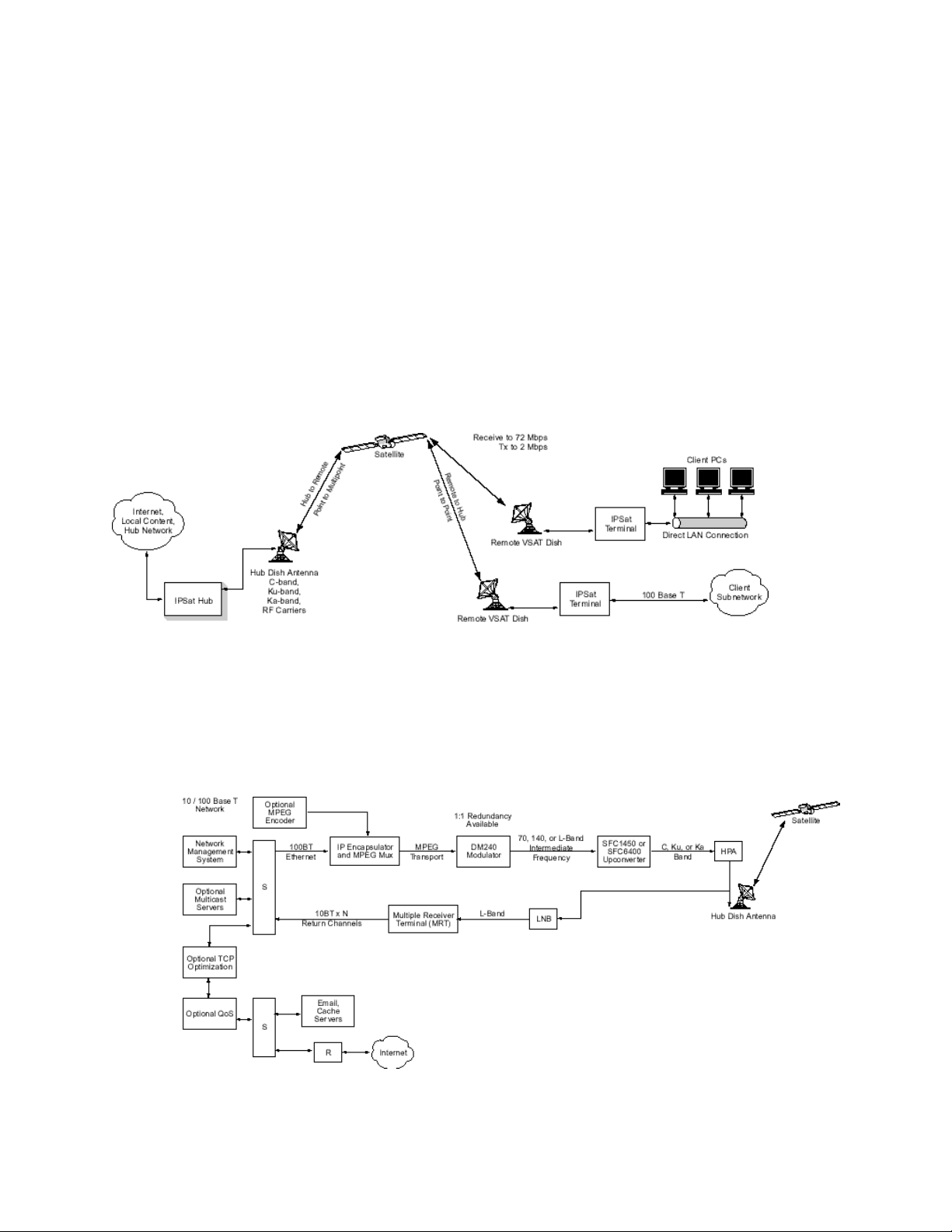
System Overview
The typical IP over-satellite system consists of a network hub with a single, very high-speed uplink broadcasting to
numerous remote stations, each of which includes an IPSat GW1000 terminal.
The IPSat GW1000 Terminal is part of a satellite-based IP network that allows remote sites high-speed
communications access to and from LAN/WAN links. The IPSat GW1000 provides full two-way connectivity to the
hub over a satellite channel and to a local Ethernet network through a standard 10/100Base-T interface. The hub
receives inbound SCPC satellite carriers from IPSat GW1000 remote terminals through a Multiple Receive Terminal
(MRT), offering up to 12 demodulators in only nine rack units of space.
The hub system is scalable from 1 to 72 Mbps outbound and can support virtually any number of satellite return
channels. Any combination of Internet protocol data streams, both TCP and UDP, unicast and multicast, may be
carried between the hub and remote stations. Radyne ComStream can also integrate additional networking
equipment and applications based on your system requirements.
Basic Network Topology Diagram
Hub Equipment
While the networking equipment used in the hub will vary greatly with the particular application of the network, the
basic core of the system remains the same and includes the following:
• Internet Protocol Encapsulator (IP Encapsulator)
• Satellite Modulator, DM-240
• Multiple Receiver Terminal (MRT)
• Optional Equipment
Hub Network Functional Block Diagram
1 01-0945-401 Rev A 08/2004
Page 12

Internet Protocol Encapsulator (IPE)
The IPE receives data from the hub IP network and encapsulates the data into a MPEG transport stream according to
DVB data broadcast specification EN 301 192.
Satellite Modulator DM-240
The DM-240 is ComStream's standard DVB-compliant satellite modulator. Connecting to the IPE, the input
interfaces include DVB SPI, ASI, M2P, and RS-422. The modulator accepts the input MPEG transport stream and
provides scrambling, FEC encoding, and modulation of the satellite carrier channel in accordance with DVB
specification EN 300 421.
Multiple Receiver Terminal (MRT)
The MRT is a 9 rack-unit chassis housing redundant, hot-swappable AC power supplies, L-band amplifiers and
distribution, and up to 12 SCPC demodulators.
The chassis includes integrated cooling fans and front panel LEDs showing status of all installed demodulators. The
demodulator cards are hot swappable and operate between 19.2 kbps to 8.448 Mbps, meeting the same performance
specifications as ComStream’s standard DBR2000 receiver. Each demodulator is connected to a Cisco router, which
provides a standard Ethernet interface to the hub Ethernet network for return channel traffic from remote stations.
Optional Equipment
Based on the system application, a network may require additional equipment including:
• MPEG video and audio encoders
• TCP optimization hardware
• Quality of service (QoS) or traffic-shaping hardware
• Basic network equipment
• Application servers
2
01-0945-401 Rev. A 08/2004
Page 13
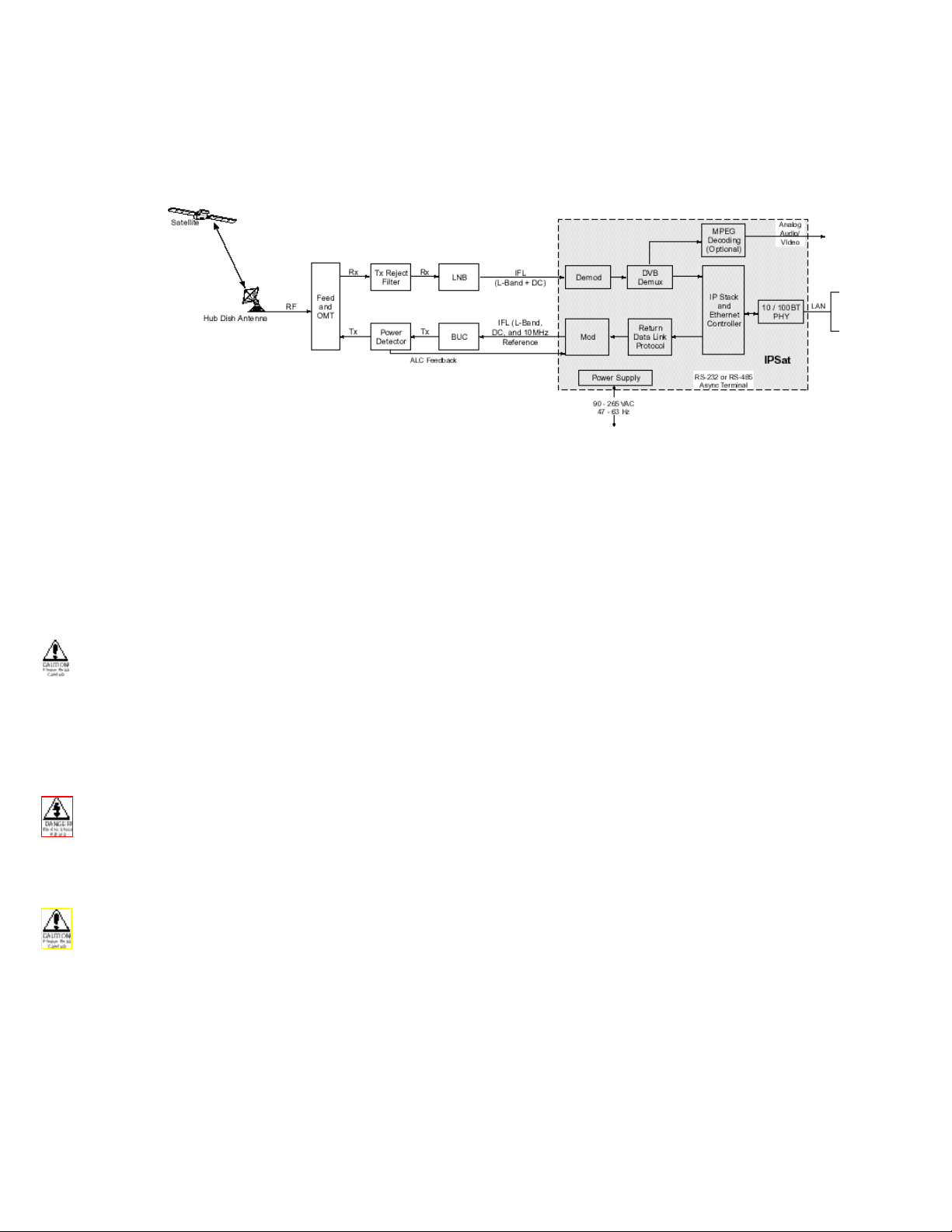
IPSat GW1000 Overview
The IPSat GW1000 Terminal is an integrated two-way SCPC satellite modem with combined IP router/bridge
functionality designed specifically to carry high-speed broadband internet traffic.
IPSat GW1000 Remote System Block Diagram
The IPSat GW1000 Terminal is a two rack-unit chassis including a DVB-compliant demodulator, MPEG transport
demux, IP stack processor, and Ethernet controller functions. Innovative design of the receive path allows use of up
to the full satellite channel bandwidth to output to the Ethernet port.
IP data passed to the IPSat GW1000 Ethernet port is accepted and processed based on internal static routing tables,
framed in HDLC packets, and passed to the satellite modulator. The modulator scrambles, FEC encodes, and
modulates the data on an L-band IF carrier for transmission to the satellite. Up to 64 static routes may be defined in
the IPSat GW1000.
Connecting multiple client computers through an Ethernet Hub may cause data collisions and subsequent loss of
data. To resolve this potential issue, Radyne ComStream strongly recommends the use of an Ethernet Switch on the
IPSat GW1000 Ethernet interface.
Installation
This chapter provides step-by-step procedures for installing and cabling the IPSat GW1000 and a description of all
IPSat GW1000 rear panel connections and required cables.
Do not remove the IPSat GW1000 top cover! The IPSat GW1000 is powered by an exposed, switching AC power
supply which presents an electric shock hazard when the top cover is removed. Personal injury or damage to the
equipment can occur when the top cover is removed. None of the procedures in this manual require the removal of
the IPSat GW1000 top cover.
Before beginning your installation, read the Safety Precautions as they contain important safety information and
other instructions required to install the IPSat GW1000.
When installing the IPSat GW1000, always position the equipment to allow easy access to the rear panel and
provide adequate ventilation.
To properly install the IPSat GW1000, follow the instructions provided in the shipping kit.
3 01-0945-401 Rev A 08/2004
Page 14
Ventilation
It is important that all installations allow adequate ventilation to the IPSat GW1000 at all times. To keep the system
cool and running smoothly, the power supply-cooling fan exhausts air through grillwork openings on the rear panel
and pulls external air through the slots at the sides of the unit.
The minimum airflow clearance space is three inches at the sides of the IPSat GW1000 and six inches at the rear.
Required Cables
For detailed information on cable specifications, including cable pinouts, connector drawings, and cable lengths,
refer to the appendix on cable specifications.
The following cables are used to connect the IPSat GW1000 Terminal:
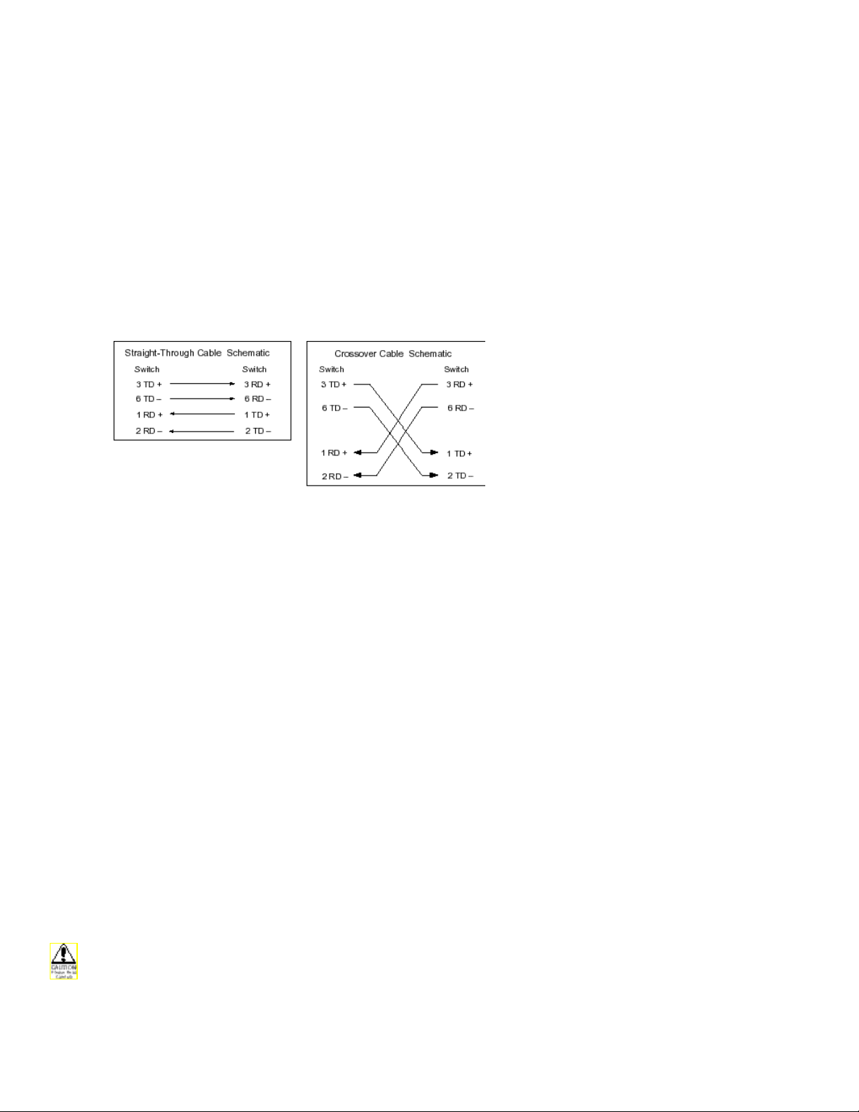
• RJ45 Cat 5 10/100 BaseT Ethernet cable, either straight through or crossover. This cable connects the
10/100 BaseT port to a standard Ethernet interface.
• RS-232 serial cable. This cable connects the console port to a console.
Coaxial cables:
• IFL TX Cable: TX Out Cable, part number 05-0954-001 (supplied). This cable connects the Tx out
port to either the optional attenuator or to the LMR 400 cable.
• IFL TX Cable: LMR 400, 50 ohm coax terminated with N-type connectors. This cable connects either
the optional attenuator to the upconverter, or the TX Out cable, 05-0954-001, to the upconverter.
Three signals are on the IFL coaxial cable to the ODU:
• 10 MHz reference which is a reference oscillator for ODU synthesizer
• DC power (24V @ 3 amp) for the ODU.
• TX carrier signal (L-band)
• Rx Cable: Quad shielded RG-11 coax terminated with F-type connectors. This cable connects the
Tx/Rx port to the LNB.
• Video interface (Video port)
• Audio Left Port and Audio Right Port
• AC Power Cords: The IPSat GW1000 shipping kit includes two AC power cords, one for North
American applications, specifically the United States and Canada, and the other for international
applications.
North American Applications: the North American cord has an IEC-compatible female plug on one end and a North
American male plug on the other. This cord is UL and CSA approved up to 125VAC at 10A. This cord is ready to
use with no user wiring required.
International Applications: The international cord has an IEC-compatible female plug on one end and three stripped
and tinned bare wires on the other end. This cord is approved by many international safety agencies, including VDE,
up to 250VAC at 6A.
AC wiring must be done in accordance with governmental standards and codes in effect at the IPSat GW1000
installation site. Refer to the Safety Precautions for additional information.
4
01-0945-401 Rev. A 08/2004
Page 15
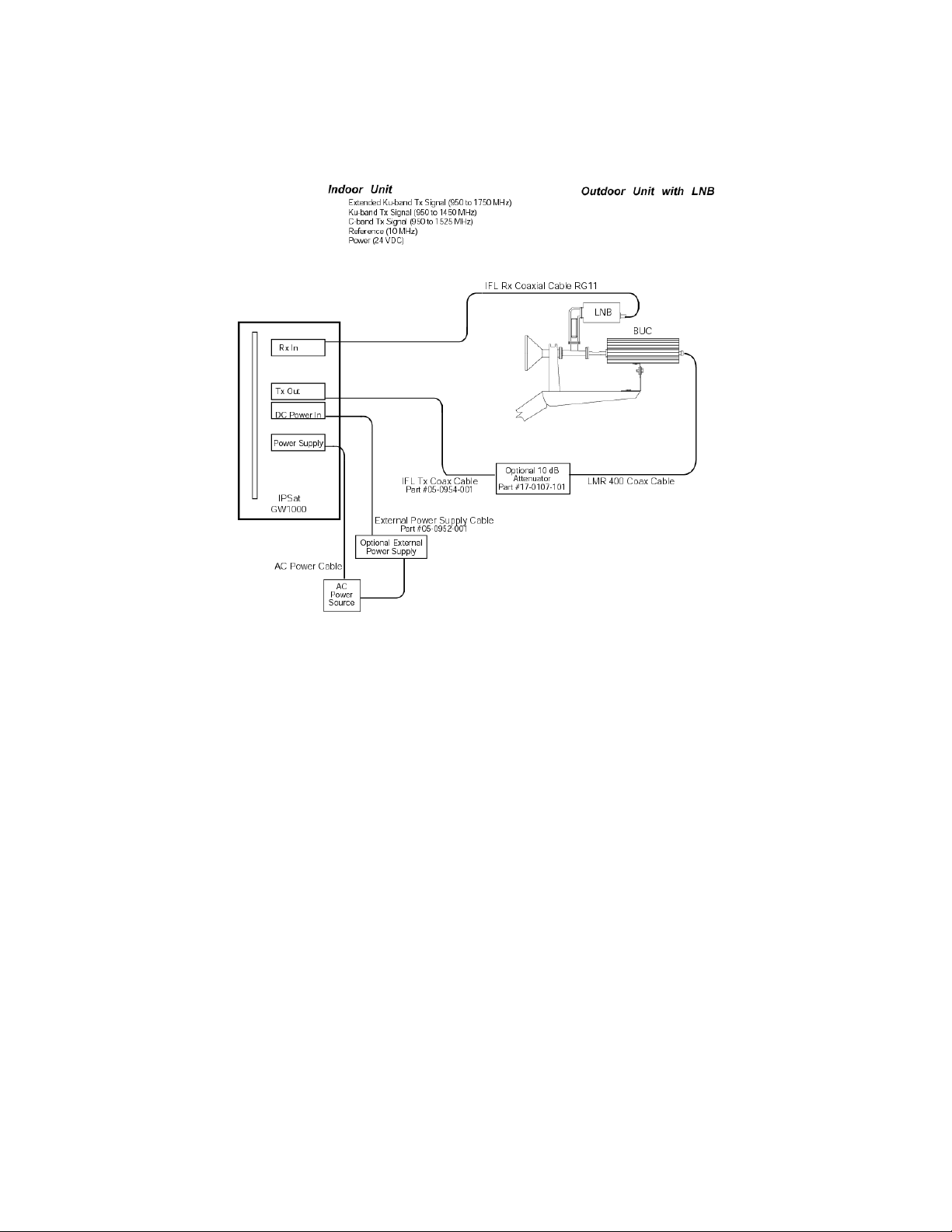
Cabling the IPSat GW1000
Refer to the following diagram when cabling the IPSat GW1000. For a more detailed description of the IPSat
GW1000 interconnections, refer to the Rear Panel Connections Section later in this chapter.
IPSat GW1000 Cabling
To connect the cables to the IPSat GW1000 terminal, follow these steps:
1 Place the IPSat GW1000 AC switch in the Off position.
2 Connect the IPSat GW1000 ground stud, located to the lower right of the fan on the rear panel, to the rack
ground, or to another solid connection to earth ground with heavy gauge wire.
3 Connect the IPSat GW1000 to the upconverter. If an optional attenuator is required, follow step 3b.
a. Connect the IFL TX coaxial cable, part number 05-0954-001, from the IPSat GW1000 TX Out Port to
the LMR 400 coaxial cable. Then connect the LMR 400 coaxial cable to the upconverter input.
b. If an optional Attenuator is required, connect the IFL TX coaxial cable, part number 05-0954-001,
from the IPSat GW1000 TX Out Port to the Attenuator. Then connect the Attenuator to the
upconverter input using the LMR 400 coaxial cable.
4 Connect the IPSat GW1000 to the LNB. Connect the RG-11 IFL Rx coaxial cable from the IPSat GW1000
Rx In Port to the LNB output. The LNB is a standard DRO or PLL type used to convert the received C, Ku,
or Ka-band carrier to L-band. Two signals are present on the IFL coaxial cable:
• RF carrier signal (L-band)
• DC power
5 Connect the IPSat GW1000 to a remote terminal. Connect the RS-232 cable from the IPSat GW1000
console port to a terminal or PC with Terminal emulation software, such as HyperTerminal, installed.
6 Connect the IPSat GW1000 to an Ethernet interface by doing one of the following:
5 01-0945-401 Rev A 08/2004
Page 16

• Connect the CAT 5 straight-through cable from the IPSat GW1000 Ethernet 10/100 BaseT port to a
10/100 port on a switch.
• Connect the CAT 5 crossover cable to a 10/100 port on a server, PC, or TCP Optimizer.
7 Connect an external power supply to the IPSat GW1000, if required.
• Ensure that the external power supply equipment is turned Off.
• Connect the external power supply cable, part number 05-0952-001, from the DC Power In connector
to the external power supply equipment. Then connect the external power supply equipment to an
AC outlet according to that manufacturer’s instructions.
8 Connect the IPSat GW1000 to an AC power source.
• Ensure the IPSat GW1000 power switch is in the Off, or 0, position.
• Select an AC power cord. If an international power cord is selected, attach a connector in accordance
with local regulations and laws.
• Connect the female plug of the AC power cord to the AC power receptacle on the IPSat GW1000 rear
panel.
• Connect the male plug of the AC power cord to an external AC power conditioning surge suppressor.
• Connect the AC power conditioning surge suppressor to an AC outlet.
Corrupted AC input power can interrupt IPSat GW1000 operations and cause permanent damage to the unit. You
should purchase and install a commercially available, external AC power conditioning surge suppressor to protect
the IPSat GW1000 against power spikes and line transients.
Powering On The IPSat GW1000
Once the cabling and interconnections for the IPSat GW1000 are completed, you may power-up the unit. The IPSat
GW1000 power switch is a rocker switch located on the rear panel.
The power switch is labeled with a — and an 0. The — represents the On position, while the 0 represents the Off
position.
To power up the IPSat GW1000, press the power switch to the ON, or — position. The power-on cycle takes
approximately three to four minutes to complete, as the unit performs extensive self-diagnostics in this time period.
6
01-0945-401 Rev. A 08/2004
Page 17

Basic Configuration
Before proceeding with the configuration, obtain the basic installation information at the end of this chapter.
Set the console terminal emulation program (HyperTerminal) to the factory default of 19200 bps, 8 bits, no parity, 1
stop bit and no flow control.
Press the Esc key. The following screen should appear:
Navigate to the Main Menu by pressing the space bar. The following screen should appear:
7
01-0945-401 Rev. A 08/2004
Page 18

Navigate to the Configuration Menu by pressing 1. The following screen should appear:
Navigate to the Basic Configuration Menu by pressing 1. The following screen should appear:
8
01-0945-401 Rev. A 08/2004
Page 19

Most of the IPSat GW1000 configuration can be performed with the Basic Configuration Menu. The parameters are
defined as follows:
IP Address: Used to identify the IPSat GW1000 on the network and is usually defined by your service provider
Subnet Mask: Used by the IPSat GW1000 in conjunction with its IP address to make forwarding decisions and is
usually defined by your service provider.
Default Gateway: Used in situations where one or more routers exist on the IPSat GW1000’s subnet accessible
through the Ethernet interface. When a packet is received from the DVB channel and the IPSat GW1000 determines
that the packet contains a destination IP address that is not on its own subnet, the IPSat GW1000 forwards the packet
to a gateway. The gateway is chosen by searching the static routes that have been defined; if no static route exists to
handle the destination network, the packet is forwarded to the default gateway. Note: The default gateway (and static
route) configuration only applies to forwarding decisions made on packets received by the DVB port (demodulator
or receive port), not packets received by the Ethernet port. Packet received by the Ethernet port that contains an
unknown destination network will be forwarded out the HDLC port (modulator or transmit port).
MPEG PID 1: When a PID (Program Identifier) value is entered, the IPSat GW1000 will accept and process all
traffic received by the DVB port (demodulator or receive port) that contains the PID value. At least one PID must be
entered to receive DVB traffic and is usually defined by your service provider.
Subscribed Rx BW: Enter the amount of bandwidth that the IPSat GW1000 is subscribed to receive from the
service provider. The IPSat GW1000 uses this parameter to accurately reflect the network activity on the front panel
display.
RC-Rx coding rate: Sets the type and rate of the FEC (Forward Error Correction) decoding performed by the
demodulator. Defined by service provider. Default is Vit 2/3.
RD-Rx Data Rate: Sets the data rate in bps (bits per second) that the demodulator receives at and is usually defined
by your service provider. The Rx Symbol Rate is automatically determined by the Rx Coding Rate and the Rx Data
Rate.
RS-Rx Frequency: Sets the L-band frequency in Hz (hertz) that the demodulator receives at and is usually defined
by your service provider.
TC-TX Coding Rate: Sets the type and rate of the FEC (Forward Error Correction) coding performed by the
modulator. Defined by service provider. Default is Vit 1/2. Note: When the service provider is using Radyne
ComStream’s MRT (Multiple Receiver Terminal), the TX Coding Rate must use the DVB symbol-mapped Viterbi
types (DVB 1/2, DVB 3/4, DVB 7/8) or the sequential types.
TD-TX Data Rate: Sets the data rate in bps (bits per second) that the modulator transmits at and is usually defined
by your service provider. The TX Symbol Rate is automatically determined by the TX Coding Rate and the TX Data
Rate.
TS-TX Frequency: Sets the L-band frequency in Hz (hertz) that the modulator transmits at and is usually defined
by your service provider.
TP-TX Power Level: Determines the power level in dBm (decibel-meter) that the modulator transmits at. Default is
0.0dbm.
EM-Modulator: Enables or disables the modulator. It performs the same function as pressing TX Enable on the
front panel. Default is disabled.
HP-10 MHz Reference: Enables or disables 10 MHz BUC (Block UpConverter) reference frequency. Default is
disabled.
MIV-24 Volt Output: Selects the source for the power to the BUC (Block UpConverter). Choices are disabled,
enabled internal and enabled external. Default is disabled. Note: Enabled internal has a maximum of 24vdc at 3
AMPS.
AE-Modulator Auto Enable: Used to automatically return the modulator, 10 MHz and 24vdc to previous state
upon power-up or reset when set to Auto; otherwise, when set to manual, the modulator must be manually enabled
upon power-up or reset. Default is Manual.
PC-Pure Carrier: Enables or disables the transmission of an unmodulated carrier (continuous wave) out of the
modulator. The pure carrier signal is used for diagnostic and installation procedures. Default is disabled.
Once all of the parameters have been configured, press the Esc key. A reset may be required for some of the settings
to take effect. If this is the case, the IPSat GW1000 will reset itself after displaying a user prompt.
Refer to the Console chapter for more information about configuration and monitoring tasks and utilities that are
available.
9
01-0945-401 Rev. A 08/2004
Page 20

Rear Panel Connections
All IPSat GW1000 external connections are located on the rear panel.
IPSat GW1000 Rear Panel
External Input Power Supply Port
The DC Power In port supplies up to 48 VDC at 6 amps to the IFL cable for external (UPA).
Connector: Mini-UHF connector
Transmit Out Port
The TX Out port provides the transmit IF output, reference, and DC power to the ODU transmitter. The IPSat
GW1000 modulator has electronically adjustable output power. For normal IPSat GW1000 operations, the output
power of the L-band modulator is set between –35 and 8 dBm, in 0.1 dB steps. The output frequency is
programmable in the range of 950 to 1750 MHz.
The output impedance is 50 ohms, with a return loss of 8 dB or better.
Connector: Mini-UHF connector
Optional Power Detector Port
The Tx/Rx port uses a Y-cable to interface with optional power detector and/or user data equipment. This port
provides DC and receives a 4 to 400 KHz signal for the optional BUC power detector for closed loop power control.
Connector: DB26 HD
Receive Input Port
The Rx In port receives the L-Band IF signal for the ODU and provides DC power to the ODU LNB. The power of
the input signal must be in the range of –30 to –65 dBm. The IF frequency must be in the range of 950 to 1750 MHz.
The input impedance is 75 ohms, with a return loss of 8dB or better.
Connector: F connector
Audio Output Ports Left and Right
The Audio Left and Audio Right Output ports supply the analog audio outputs for audio channels 1 and 2. The peak
output level is approximately –3 dBu and the output are matched for 600-ohm impedance.
Connectors: stereo pair on RCA jacks, +18 dBU maximum, 0 dB throughput gain nominal.
Video Output Port
The Video Output port supplies the composite analog (NTSC or PAL) video output signal to the user monitor. The
output impedance is 75 ohms. Connector: RCA jack.
Console Port
The Console port provides an RS-232 interface between the IPSat GW1000 and a console.
Connector: DB 9 connector
Ethernet Port 10/100 BaseT Port
The Ethernet 10/100 BaseT port supports auto-negotiation by default. Optionally, speed and duplex can be manually
set.
Connector: 10/100BaseTX per IEEE 802.3u on an RJ-45 connector.
Power Supply
The rear panel AC power supply interface includes an On/Off (I/0) power switch, a cooling fan vent, and an IEC
320 power cord receptacle.
The IPSat GW1000 is powered by an auto-sensing, auto-ranging AC switching power supply. The power supply
accepts 85 to 240VAC nominal input voltage levels cycling at 47 to 63 Hz.
10 01-0945-401 Rev A 08/2004
Page 21

Basic Installation Information Sheet
Basic Installation Information
General Information
Date___________________Installer___________________________________________
Site location_______________________________________________________________
Custom er
Nam e _____________________ P .O.C. and phone # _____________________________
Satellite
Nam e _________________________Longitude (degrees) __________________________
Operating band
Earth Station
Antenna
Size____________________-___Manufacturer__________________________________
ODU Information
IDU Configuration
Param eters
Netw o rk Param eters
• C-ba nd
• Ku-band
Altitude (feet) ______________
Longitude (degrees/minutes) ____________ Latitude (degrees/minutes)___________
Offset angle (deg) ___________________(for offset antennas nominally 22.5°)
Elevation angle (deg) ________________ Azimuth angle (deg) _________________
Polarization angle (deg) ___________________
Radio transm itter gain ________________
IFL cable length ________________ IFL cable Type ________________
Data rate (bps) __________________ ______________________
Frequency (hz) __________________ ______________________
Coding Rate __________ __________
IPSat IP Address _______________ Subnet Mask ______________________
Default Gateway _______________________
Mpeg PID 1 _______________
Transmit
Polarization
• Linear Co-Pol
• Circular RHCP
Magnetic deviation degrees/minutes)_________
LNB Type ____________________
Mpeg PID 2 ____________
• Cross-Pol
• LH C P
Receive
11
01-0945-401 Rev. A 08/2004
Page 22

Front Panel Operation
This section describes the feedback system of the IPSat GW1000 front panel:
Front Panel Components
The front panel is broken into the following sections:
Status
• Power: Illuminates green when powered on
• Fault: Illuminates red when a fault is active
• Tx Enabled: Illuminates green when the modulator is enabled
• Ethernet Speed: Illuminates green when speed is 100mbps. Illuminates orange when speed is
10mbps.
• Ethernet Duplex: Illuminates green when duplex is full. Illuminates orange when duplex is half.
RF Signal (Eb/No)
• Max: Illuminates green if Eb/No is 11 or above
• . : Illuminates green if Eb/No is 10 or above
• . : Illuminates green if Eb/No is 9 or above
• . : Illuminates green if Eb/No is 8 or above
• Min: Illuminates green if Eb/No is 5 or above
• Sync: Illuminates green if demodulator has achieved synchronization
Activity (Rx)
• Max: Illuminates yellow if 90% of Rx Subscribed BW is above or is being utilized
• . : Illuminates green if 80% of Rx Subscribed BW or above is being utilized
• . : Illuminates green if 70% of RX Subscribed BW or above is being utilized
• . : Illuminates green if 60% of Rx Subscribed BW or above is being utilized
• . : Illuminates green if 50% of Rx Subscribed BW or above is being utilized
• Min: Illuminates green if 1% of RX Subscribed BW or above is being utilized
Activity (Tx)
• Max: Illuminates yellow if 90% of Tx Data Rate or above is being utilized
• . : Illuminates green if 80% of Tx Data Rate or above is being utilized
• . : Illuminates green if 70% of Tx Data Rate or above is being utilized
• . : Illuminates green if 60% of Tx Data Rate or above is being utilized
• . : Illuminates green if 50% of Tx Data Rate or above is being utilized
• Min: Illuminates green if 1% of Tx Data Rate or above is being utilized
12 01-0945-401 Rev A 08/2004
Page 23

IPSat GW1000 Console Design
IPSat GW1000 Menu Tree
The IPSat GW1000 console provides a menu-driven interface in a tree structure as detailed below. Notice that there
are three main categories of functions: Configuration, Status, and Utilities. A description of each function can be
found in the chart 5.1.
1. Main Menu
1.1 Configuration
1.1.1 Basic
1.1.2 Advanced
1.1.2.1 Network
1.1.2.1.1 Ethernet
1.1.2.1.2 IP
1.1.2.1.2.1. Static Routes
1.1.2.1.2.2. Multicast Control
1.1.2.1.3 ARP
1.1.2.1.4 HDLC
1.1.2.1.5 NMS Control Address
1.1.2.2 MODEM
1.1.2.2.1 Modulator
1.1.2.2.2 Demodulator
1.1.2.3 DVB/MPEG
1.1.2.3.1 PID Table
1.1.2.3.2 MAC Filtering
1.1.2.3.3 Audio/Video
1.1.2.4 Console
1.1.2.5 Security
1.1.2.5.1 Telnet Control
1.1.2.5.2 Telnet/Console Password
1.1.2.5.3 Telnet Timeout
1.1.2.5.4 Local Ping Control
1.1.2.5.5 Console Password Control
1.1.2.6 Faults
1.1.2.6.1 Realtime Fault Mask
1.1.2.6.2 Fault Log Mask
1.2 Status
1.2.1 Network
1.2.1.1 Ethernet Port Status
1.2.1.2 IP
1.2.1.2.1 Forwarding Table
13 01-0945-401 Rev A 08/2004
Page 24

1.2.1.2.2 Routed Packet List
1.2.1.3 ARP Table
1.2.2 MODEM
1.2.3 DVB/MPEG
1.2.4 Packet Statistics
1.2.5 Firmware Versions
1.2.6 Faults
1.2.6.1 Current Faults
1.2.6.2 Fault Log
1.3 Utilities
1.3.1 Ping
1.3.2 Loopback
1.3.2.1 Test
1.3.2.2 Test Statistics
1.3.3 Initialize Configuration
1.3.4 Firmware Upgrade
1.3.5 Debug Commands
1.3.5.1 Forward Channel Processor Commands
1.3.5.2 Packet Capture Commands
1.3.5.2.1 Packet Capture Control
1.3.5.2.2 View Packet Capture
1.3.5.2.3 Erase Packet Capture
1.3.5.2.4 Load Saved Packet Capture
1.3.6 Reset
14
01-0945-401 Rev. A 08/2004
Page 25

IPSat GW1000 Console Parameters
The following chart provides a description of all of the parameters that can be configured and monitored on the
IPSat GW1000.
Main Menu →
Configuration → Basic
[1] IP Address: Used to identify the
IPSat GW1000 on the network and is usually
defined by your service provider.
[2]
Subnet Mask: Used by the IPSat
GW1000 in conjunction with its IP address to
make forwarding decisions and is usually
defined by your service provider.
Default Gateway: Used in situations
[3]
where one or more routers exist on the IPSat
GW1000's subnet accessible through the
Ethernet interface. When a packet is received
from the DVB channel and the IPSat
GW1000 determines that the packet contains
a destination IP address that is not on its own
subnet, the IPSat GW1000 forwards the
packet to a gateway. The gateway is chosen
by searching the static routes that have been
defined; if no static route exists to handle the
destination network, the packet is forwarded
to the default gateway. Note: The default
gateway (and static route) configuration only
applies to forwarding decisions made on
packets received by the DVB port
(demodulator or receive port), not packets
received by the Ethernet port. Packets
received by the Ethernet port that contain an
unknown destination network will be
forwarded out the HDLC port (modulator or
transmit port).
[4]
Identifier) value is entered, the IPSat
GW1000 will accept and process all traffic
received by the DVB port (demodulator or
receive port) that contains the PID value. At
least one PID must be entered to receive
DVB traffic and is usually defined by your
service provider.
[5]
amount of bandwidth that the IPSat GW1000
is subscribed to receive from the service
provider. The IPSat GW1000 uses this
parameter to accurately reflect the network
activity on the front panel display.
[6]
rate in bps (bits per second) that the
demodulator receives at and is usually
defined by your service provider. The Rx
Symbol Rate is automatically determined by
the Rx Coding Rate and the Rx Data Rate.
[7]
MPEG PID 1: When a PID (Program
Subscribed Rx BW: Enter the
RD - Rx Data Rate: Sets the data
RS - Rx Frequency: Sets the
15
01-0945-401 Rev. A 08/2004
Page 26

frequency in Hz (hertz) that the demodulator
receives at and is usually defined by your
service provider.
TC - TX Coding Rate: Sets the
[8]
coding rate that the modulator will use and is
usually defined by your service provider.
TD - TX Data Rate: Sets the data rate
[9]
in bps (bits per second) that the modulator
transmits at and is defined by your service
provider. The TX Symbol Rate is
automatically determined by the TX Coding
Rate and the TX Data Rate.
[10]
frequency in Hz (hertz) that the modulator
transmits at and is usually defined by your
service provider.
[11]
the power level in dBm (decibel-meter) that
the modulator transmits at.
[12]
disables the modulator. It performs the same
function as pressing TX Enable on the front
panel.
[13]
disables the 10 MHZ reference from the
IPSat GW1000 to the BUC (Block Up
Converter)
[14]
disables the 24v output from the IPSat
GW1000 power supply to power a BUC
(Block UpConverter). The output supplies a
maximum of 3 Amps.
[15]
Used to automatically enable the modulator
upon power-up or reset when set to Auto;
otherwise, when set to manual, the modulator
must be manually enabled upon power-up or
reset.
[16
disables the transmission of an unmodulated
carrier (continuous wave) out of the
modulator. The pure carrier signal is used for
diagnostic and installation procedures.
TS - TX Frequency: Sets the
TP - TX Power Level: Determines
EM - Modulator: Enables or
HP - 10 MHz Reference: Enables or
MIV - 24 Volt Output: Enables or
AE - Modulator Auto Enable:
] PC - Pure Carrier: Enables or
16
01-0945-401 Rev. A 08/2004
Page 27

Main Menu →
Configuration → Advanced
→ Network → Ethernet
[1] MAC Address: The Media Access
Control address (physical address) of the
Ethernet port. While it is possible to change
the address, this is not recommended since
there is no guarantee that it will be unique.
The MAC address is also used by your
service provider to identify your IPSat
GW1000.
[2] Port Setting: In Auto-negotiation
Mode, the IPSat GW1000's Ethernet port will
automatically negotiate its speed and duplex
with the Ethernet port of the device the IPSat
GW1000 is plugged into. In Manual Mode,
the console will allow the user to specify the
port speed and duplex.
Note 1: When connecting two Ethernet
devices together, both devices should be set
to use the same port settings. For example, if
the IPSat GW1000 is set to use autonegotiation, the Ethernet device it is
connected to should also use autonegotiation. If this advice is not heeded, your
network performance could be reduced due to
excessive collisions.
Note 2: The Port Speed and Port Duplex
Mode options only appear when Manual
Mode is selected for the Ethernet port.
[3] Port Speed: The manually configured
speed of the Ethernet port.
[4] Port Duplex Mode: The manually
configured duplex mode of the Ethernet port.
17
01-0945-401 Rev. A 08/2004
Page 28

Main Menu →
Configuration → Advanced
→ Network → IP → Static
Routes
When the IPSat GW1000 must forward
traffic to multiple networks that are
accessible through different routers on the
IPSat GW1000's subnet, static routes must be
used. To add a static route, press "a". You
will be prompted to enter the following:
Destination: The destination network IP
address.
Mask: The destination network subnet mask.
Gateway: The IP address of the gateway
(router) that will forward the packet to its
final destination or the next hop.
Port: The port that the incoming packet will
be forwarded out. This should always be the
Ethernet port unless a Multicast static route is
entered, in which case, the HDLC port should
be chosen.
Note: The default gateway and static route
configuration only apply to forwarding
decisions made on packets received by the
DVB port (demodulator or receive port), not
packets received by the Ethernet port.
Packets received by the Ethernet port that
contain an unknown destination network will
be forwarded out the HDLC port (modulator
or transmit port).
Configuration Example:
Consider the network diagram below for the
following discussion. Assume that Router A
can forward packets to ten different networks,
Router B can forward packets to network
192.168.34.240 with subnet mask
255.255.255.248, and Router C can forward
packets to network 192.168.34.232 with
subnet mask 255.255.255.248.
[IPSat GW1000]-------[Switch]--------[Router A]
10.0.0.1 | 10.0.0.30
|
|-------------[Router B]
| 10.0.0.35
|
|-------------[Router C]
10.0.0.40
18
01-0945-401 Rev. A 08/2004
Page 29

The easiest way to configure the IPSat
GW1000 for this network is to perform the
following three steps:
1. Configure a default gateway of 10.0.0.30
on the Basic Configuration page. Using the
default gat
gateway in this instance saves the user from
entering ten static routes.
2. Configure a static route as follows:
Destination: 192.168.34.240
Mask: 255.255.255.248
Gateway: 10.0.0.35
Port: Ethernet
3. Configure a static route as follows:
Destination: 192.168.34.232
Mask: 255.255.255.248
Gateway: 10.0.0.40
Port: Ethernet
Main Menu →
Configuration → Advanced
→ Network → ARP
Main Menu →
Configuration → Advanced
→ Network → HDLC
Main Menu →
Configuration → Advanced
→ Network → NMS
Control Address
Main Menu →
Configuration → Advanced
→ MODEM → Modulator
Determines how long an unused ARP
(Address Resolution Protocol) entry will
remain in the ARP table.
This value depends on the type of equipment
your service provider is using to process the
IPSat GW1000’s HDLC (transmitted) traffic.
16-bit address mode is used for Cisco
equipment and 0-bit address mode is used for
RAD equipment. Your service provider
should provide you with this setting.
The IP address that is used by your service
provider's NMS (Network Management
System). The NMS allows your service
provider to configure your IPSat GW1000
and gather statistics from your IPSat
GW1000.
[1] MI - TX Spectral Inversion:
Enables or disables transmit spectral
inversion. Default is Disable
[2] TM - TX Modulation Type:
Modulation type can be set to QPSK or
BPSK. This should be provided by your
service provider. Default is QPSK.
[3] TO - TX Offset: A frequency that is
added (or subtracted) to the TX frequency.
Default is 0hz.
[4] ROE - Radio Output Enable: The
amount of time that the IPSat GW1000 will
wait upon power-up or reset to automatically
enable the modulator. The BUC requires a
warm-up period in order for accurate
transmission characteristics. Default is 180
seconds.
[5] TR - TX Symbol Rate: The symbol
rate at which the modulator transmits at.
19
01-0945-401 Rev. A 08/2004
Page 30

It can be entered in sps (symbols per second).
When changing the symbol rate, the data rate
in the Basic Configuration will also change.
Symbol rate is related to data rate using the
following equation:
Symbol Rate = (Data Rate / (Code Rate x
Modulation Index))
For example, the symbol rate of a 2 Mbps,
Viterbi-DVB 3/4, QPSK transmission is
Symbol Rate = (2000000 / ((3/4) x 2)) =
1333333 sps
[6] DM - Differential Encoding on
modulator: Enables or disables differential
encoding. Used to protect from the possibility
of phase ambiguity errors. Default is on.
[7] SM - Scrambling Type on
modulator: selects type of scrambling
algorithm applied to transmit data stream.
Default is ComStream.
[8] PD - Power Detect: Enables or
disables optional power detector. Default is
disabled.
[9] MFS - Modulator Filter Select:
Selects the spectral shape of the modulated
transmit signal. Used to optimize filter shapes
between modulator and demodulator Default
is ComStream.
20
01-0945-401 Rev. A 08/2004
Page 31

Main Menu →
Configuration → Advanced
→ MODEM →
Demodulator
[1] EBT - Eb/No Threshold: When the
Eb/No falls below the Eb/No threshold, the
IPSat GW1000 will report a fault. Default is
0db.
[2] AO - Acquisition Offset: When the
demodulator begins its acquisition process, it
will begin its search at the Rx frequency plus
or minus the acquisition offset. For example,
if the Rx Frequency is 1200000000 Hz and
the acquisition offset is 1000 Hz, the
demodulator will begin its acquisition at
1200001000 Hz. Default is 0hz.
[3] DD - Differential Decoding: Enables
or disables differential decoding. Used to
protect from the possibility of phase
ambiguity errors. Default is on.
[4] RM - Rx Modulation Type:
Modulation type can be set to QPSK or
BPSK. This should be provided by your
service provider. Default is QPSK.
[5] RR - Rx Symbol Rate: The symbol
rate at which the demodulator receives at. It
can be entered in sps (symbols per second).
When changing the symbol rate, the data rate
in the Basic Configuration will also change.
Symbol rate is related to data rate using the
following equation:
Symbol Rate = (Data Rate / (Code Rate x
Modulation Index)) x Reed-Solomon
Overhead
For example, the symbol rate of a 70 Mbps,
Viterbi 7/8, QPSK transmission is
Symbol Rate = (70000000 / ((7/8) x 2)) x
(204/188) = 43404256 sps
[6] SD - Descrambling Type: enables or
disables DVB descrambling algorithm
applied to receive data stream. Default is
DVB descrambling.
[7] DFS - Demod Filter Select: Selects
the spectral shape for the digital filter. Used
to optimize filter shapes between modulator
and demodulator. Default is ComStream.
21
01-0945-401 Rev. A 08/2004
Page 32

Main Menu →
Configuration → Advanced
→ DVB/MPEG → PID
Table
When a PID (Program Identifier) value is
entered, the IPSat GW1000 will accept and
process all traffic received by the DVB port
(demodulator or receive port) that contains
the PID value. At least one PID must be
entered to receive DVB traffic and is defined
by your service provider.
Main Menu →
Configuration → Advanced
→ DVB/MPEG → MAC
Filtering
Main Menu →
Configuration → Advanced
→ DVB/MPEG →
Audio/Video
Main Menu →
Configuration → Advanced
→ Console
Enables or disables MAC Filtering. When
MAC Filtering is enabled, only DVB packets
containing the IPSat GW1000's MAC address
will be accepted and processed by the IPSat
GW1000. This value is usually defined by
your service provider.
[1] Video PID: When a Video PID
(Program Identifier) value is entered, the
IPSat GW1000 will accept and process all
traffic received by the DVB port
(demodulator or receive port) that contains
the PID value. The MPEG-2 video traffic
that is received on this PID will be output on
the RCA Video output (J82).
[2] Audio PID: When an Audio PID
(Program Identifier) value is entered, the
IPSat GW1000 will accept and process all
traffic received by the DVB port
(demodulator or receive port) that contains
the PID value. The MPEG-2 audio traffic
that is received on this PID will be output on
the RCA Audio Left and Right outputs (J80
and J81).
[3] PCR PID: When a PCR
(Programmable Clock Reference) PID
(Program Identifier) value is entered, the
IPSat GW1000 will accept and process all
traffic received by the DVB port
(demodulator or receive port) that contains
the PID value. In most cases, the PCR PID
must match the video PID so that the MPEG2 video stream can be properly decoded.
The console port speed Default is
19200,8,N,1 Note: baud rate is in bps (bits
per second).
Main Menu →
Configuration → Advanced
→ Security → Telnet
Control
Main Menu →
Configuration → Advanced
→ Security →
Telnet/Console Password
Enables or disables the IPSat GW1000's
Telnet server. Default is Disable. Only
six Telnet sessions can be active at any
given time.
The Telnet password can be entered here.
Default is IPSat GW1000. Should be
changed to a unique password for security
reasons.
22
01-0945-401 Rev. A 08/2004
Page 33

Main Menu →
Configuration →
Advanced →Security →
Console Password Control
Main Menu →
Configuration → Advanced
→ Security → Telnet
Timeout
Main Menu →
Configuration → Advanced
→ Security → Local Ping
Control
Main Menu →
Configuration →
Advanced → Faults →
Realtime Fault Mask
Main Menu →
Configuration →
Advanced →Faults →
Fault Log Mask
Main Menu → Status →
Network → Ethernet Port
Status
Main Menu → Status →
Network → IP →
Forwarding Table
Main Menu → Status →
Network → IP → Routed
Packet List
If enabled, the user must enter a password to
gain access through the console. The user
may log out of the console session by
pressing Esc at the welcome screen. If the
unit is reset, the console password will also
be required to gain access.
The amount of time that a Telnet session can
remain idle before it is terminated. Default is
5 min.
Enables or disables the IPSat GW1000's
response to ping requests received on its
Ethernet port. Default is enable.
When a fault on this page is masked, the fault
will not appear in the list of current faults if
the fault occurs. On the GW1000, the Fault
indicator on the front panel also will not light.
When a fault on this page is masked, the fault
will not appear in the Fault Log if the fault
occurs.
Link Status: Up when Ethernet port is
connected to a working Ethernet device and
Down when Ethernet port is not connected to
a working Ethernet device.
Port Operation Mode: Ethernet port can
be in auto-negotiation mode or manual mode.
Speed: Can be 100 Mbps or 10 Mbps.
Duplex Mode: Can be full-duplex or halfduplex.
Loopback Mode: Ethernet port is either
in normal mode or loopback mode.
Lists the IPSat GW1000's routing table which
includes the destination network, destination
network prefix (mask), gateway IP address of
the destination network, and the interface that
leads to the destination network. Interface 1
is Ethernet, 2 is HDLC, and 3 is Local.
Before the IPSat GW1000 can forward a
packet, it must decide which port the packet
should be forwarded out of based on the
source and destination IP addresses contained
in the packet. After the IPSat GW1000 has
made this decision, it stores the information
in the Routed Packet List. Entries time out of
the list based upon the ARP Table Timeout
setting.
23
01-0945-401 Rev. A 08/2004
Page 34

Main Menu → Status →
Network → ARP Table
Main Menu → Status →
Modem
Main Menu → Status →
DVB/MPEG
Main Menu → Status →
Packet Statistics
Before the IPSat GW1000 can send data to a
host on its Ethernet subnet, it must know the
host's physical address or MAC (Media
Access Control) address. The ARP (Address
Resolution Protocol) table contains a
MAC address and IP address mappings.
Entries
will be removed from the table
according to the ARP Table Timeout value.
Demodulator Status: Reports whether the
demodulator is synchronized or not
synchronized to a carrier signal.
Modulator Status: Reports whether the
modulator is enabled or disabled.
AGC value: The AGC (Automatic Gain
Control) of the demodulator is a gauge of
how powerful the received signal is. As the
signal strength increases, so does the AGC
value.
Eb/No: The Eb/No value is the energyper-bit with respect to noise (or signal-tonoise ratio) of the signal received by the
demodulator.
Receive Offset: The frequency difference
between the signal acquired by the
demodulator and the configured Rx
frequency.
Displays the number of packets received on
each configured PID in the DVB stream.
[DVB] Received Packets: Number of
packets received on the DVB port.
[DVB] Dropped Packets: Number of
packets received at the DVB port that could
not be forwarded due to an unresolvable
destination IP address or some other error
condition.
[DVB] Local Packets: Number of packets
received on the DVB port that are destined
for the IPSat GW1000.
[Ethernet] Transmitted Packets:
Number of packets that are transmitted out of
the Ethernet port.
[Ethernet] Received Packets: Number of
packets that are received by the Ethernet port.
[Ethernet] Receive Errors: Number of
errors that occur on received packets on the
Ethernet port. For example, if the IPSat
GW1000 receives a frame that is too short
due to an Ethernet collision, an error will be
logged. Another example would be when the
IPSat GW1000 receives traffic at a faster rate
than it can transmit.
list of
24
01-0945-401 Rev. A 08/2004
Page 35

Main Menu → Status →
Firmware Versions
Main Menu →
Status →
Faults →
Current Faults
Main Menu →
Status →
Faults →
Fault Log
Main Menu → Utilities →
Ping
Main Menu → Utilities →
Loopback → Test
[HDLC] Transmitted Packets: Number
of packets that are transmitted out of the
HDLC port.
[HDLC] Transmission Errors: Number
of errors that occur when attempting to
transmit packets out of the HDLC port.
Mpeg Packet Total: Number of packets
received in the MPEG/DVB stream.
Mpeg Packet Errors: Number of errors
received in the MPEG/DVB stream. It is
normal for a few errors to appear upon
startup or reset.
Displays the versions of firmware that are
used by the IPSat GW1000.
Any active faults will appear on this screen.
For a description of faults, please refer to the
Faults and Maintenance chapter.
The last 100 faults will appear on this screen
along with the time the fault occurred, since
the last reset. For a description of faults,
please refer to the Faults and Maintenance
chapter.
[1] Destination IP Address: The IP
address of the host that is to be pinged.
[2] Packet size: The size of the payload
contained in the ping.
[3] Number of packets: The number of
packets to send to the host.
[4] Send Ping(s): Initiates the ping
process. Pressing the ESC key will abort the
ping task.
[1] Loopback IP Address: The IP
address that the IPSat GW1000 will send
back through its HDLC port.
[2] Loopback Test (Hardware): Starts
or stops the loopback mode.
25
01-0945-401 Rev. A 08/2004
Page 36

Main Menu → Utilities →
Loopback → Test Statistics
Main Menu → Utilities →
Initialize Configuration
Main Menu → Utilities →
Firmware Upgrade
Main Menu → Utilities →
Debug Commands →
Forward Channel Processor
Commands
Main Menu →
Utilities →
Debug Commands →
Packet Capture Commands →
Packet Capture Control
Main Menu →
Utilities →
Debug Commands →
Packet Capture Commands →
View Packet Capture
Main Menu →
Utilities →
Debug Commands →
Packet Capture Commands →
Erase Packet Capture
Main Menu →
Utilities →
Debug Commands →
Packet Capture Commands →
Save Packet Capture
Main Menu →
Utilities →
Reset
DVB Receive Packets: The number of
packets received at the DVB port during
loopback testing.
HDLC Transmit Packets: The number of
packets transmitted out of the HDLC port
during loopback testing.
Answering Yes will return all of configured
settings to their factory default values.
When new features are added or "bugs" are
fixed, a firmware upgrade is required. The
firmware can be downloaded to the IPSat
GW1000 using the console interface or your
provider may choose to download it through
the DVB stream. For the fastest console
download, the console port speed should be
set to 115200 bps and 1K X-MODEM should
be used as the transfer protocol. Note: While
a firmware upgrade is being downloaded, the
IPSat GW1000 will not forward any network
traffic.
This is a debugging tool and should only be
used under the direction of Radyne
ComStream customer support.
Enables or disables the capturing of the last
XXX packets the IPSat GW1000 received on
its Ethernet port.
Decodes the packets captured by the IPSat
GW1000.
Answering “Y” erases from non-volatile
memory the packets captured by the IPSat
GW1000.
Answering “Y” saves the packets captured by
the IPSat GW1000 to non-volatile memory.
Answering “Y” will cause IPSat GW1000 to
reset.
26
01-0945-401 Rev. A 08/2004
Page 37

Faults and Maintenance
Fault Description
Rx Sync Fault Forward channel demodulator is not synchronized to the satellite signal.
Low Eb/No Fault Receive Eb/No is below its defined threshold.
Short Circuit Fault Tx IFL cable has been short-circuited.
Tx Fault Modulator transmit fault.
Tx Power Control Fault Modulator Tx power control circuit has exceeded its dynamic range.
Modem NvRam Fault A corruption of the modems non-volatile memory was detected.
MPC860 NvRam Fault A corruption of the TCP/IP stack processor non-volatile memory was detected.
Mpeg NvRam Fault A corruption of the MPEG processor non-volatile memory was detected.
Mpeg_Sync_Fault The MPEG processor is not synchronized to a valid MPEG transport stream.
IPC Com Fault processor A communication fault occurred between the MPEG and the TCP/IP stack
processor.
Buffer Allocation Fault No buffers available for the TCP/IP stack processor.
Tx Queue Fault No buffers available for the transmitter.
Ethernet Link Fault Ethernet cable not detected.
Troubleshooting Tips
The troubleshooting tips in the following table were designed to help you diagnose and correct minor operational
problems in the unlikely event that you experience difficulties with your IPSat GW1000 Remote Terminal.
For the problems listed, solutions are provided to help you troubleshoot IPSat GW1000 difficulties. If you try all the
suggested solutions and the unit still fails, call Radyne ComStream Customer Service.
Trouble Shooting Common IPSat GW1000 Problems
Problem Possible Causes Solutions
No main menu at
terminal
Carrier is not being
transmitted
IPSat GW1000 will
not acquire the
incoming carrier
IPSat GW1000 is not receiving
power.
The RS232 cable is not properly
connected.
Parity and baud rate parameters are
not properly configured.
IPSat GW1000 is set for external
timing.
10 MHz Ref is not enabled. Enable 10 MHz Ref in console.
24 VDC for BUC not enabled. Select 24 Internal for External from console. External
The Eb/N0 level is too low. Check the cabling to the satellite dish. Check that the
Cables are not connected properly. Check that all cables are connected correctly.
Modulator output is not enabled at
the far end.
Modulator and demodulator
parameters are not compatible.
Signal-to-noise ratio is not correct. Check that the signal-to-noise ratio is sufficient.
If operating in QPSK mode, there
may be a spectral inversion problem
introduced in the up conversion or
down conversion process.
Check that power is being supplied to the unit—some
front panel LEDs should be lit.
Check that the RS232 cable is connected using the serial
cable provided.
Check that the selected parity, 8/none, default 19200, 8,
none, 1 and baud rate match that of the terminal.
Set to internal.
requires external power supply.
modem is configured properly. Check antenna alignment.
Check that the modulator output is enabled at the far end.
Check that the modulator and demodulator configuration
parameters are compatible.
Use DI command to compensate for this.
27 01-0945-401 Rev A 08/2004
Page 38

Signal is not present on the Rx IF
connector.
IPSat GW1000
experiences
occasional decoder
synchronization loss,
but no loss of carrier
tracking or bit time
lock.
Rain fades or other loss of signal
power will cause decoder faults
before carrier tracking or bit timing
faults.
The IPSat GW1000 requires no periodic or preventive maintenance and is designed to deliver years of maintenancefree service. The only task you need to perform is keeping the air intake grill free of debris, blockage, or excessive
dust to ensure that the IPSat GW1000 receives adequate airflow.
If you do clean the IPSat GW1000, first remove power from the unit. Then clean the cabinet, panel, and controls
with a soft cloth lightly moistened with water.
Do not use any type of abrasive pads, scouring powders, liquid cleaners, aerosol cleaners, or solvents such as
alcohol or benzene.
Check the AG parameter to ensure that a signal is present
on the Rx IF connector. A value of 255 indicates no
signal; a value of 80 to 135 indicates a good signal level.
Make sure that the Eb/N0 level is sufficient.
28
01-0945-401 Rev. A 08/2004
Page 39

Appendix A
Technical Specifications
General Specifications
Chassis 2RU rack-mountable in standard 19" rack. Approximately 15" deep
and 13” wide.
Power 90 to 265 VAC, 47 to 63 Hz
Integrated line filter
Internal supply will source up to 5W BUCs; external power supply
for larger BUCs available
Cooling Forced air; air inlet on side panels, exhaust on rear panel
At least 2 inches free air space on back and sides for air flow
required
Environmental 0 to 50 degrees C ambient, 5 to 95% RH, non-condensing
Vibration as normally encountered in stationary hub facility
Regulatory CE Mark approval pending, others upon request
Monitor & Control Available through, RS-232 console, TELNET, or optional Network
Management System
Demodulator Specifications
RF Input
Symbol Rates
Data Rates
Demodulation
DVB Forward Error
Correction
DVB Mode BER Performance
BERT
RF Output
RF Output Power
RF Step Size
Symbol Rates
Data Rates
Modulation
FEC Modes
Scrambler
Differential Encoding
Phase Noise
Spurious
BERT
50 to 2150 MHz
–20 to –65 dBm carrier power
–10 dBm maximum aggregate power
1.0 to 45.0 Msps
1.0 to 72.5 Mbps
QPSK
Viterbi rate 1/2, 2/3, 3/4, 5/6, and 7/8 inner decoder
DVB-compliant deinterleaver
DVB Reed-Solomon rate 188/204 outer block decoder
DVB synchronous descrambler
Compliant with DVB-S standard, EN 300 421
per EN 300 421
RS-422 electrical
Synchronous clock and data
1/8th aggregate data rate (less RS sync byte)
Modulator Specifications
950 to 1750 MHz
+8 to –35 dBm carrier power adjustable in 0.1 dB steps
1 kHz
19.2 Ksps to 2.048 Msps
9.6 Kbps to 2.048 Mbps
BPSK or QPSK
Intelsat mapped symbols per IESS 308; 1/2, 3/4, and 7/8 rate
DVB mapped symbols per EN300 421; 1/2, 3/4, and 7/8 rate
Radyne ComStream Sequential 1/2 and 3/4 rate
V.35 asynchronous scrambler in Viterbi only
Included in Viterbi and Sequential
Compatible with IESS 308
Compatible with IESS 308
RS-422 electrical
Synchronous clock and data
1/8th aggregate data rate (less RS sync byte)
29 01-0945-401 Rev A 08/2004
Page 40

Ethernet Data Interface
Ethernet Mode
LED Indicators
MPEG Transport Processing
Aggregate Transport Data Rate
Filtered Transport Data Rate
Ethernet Throughput Rate
Routing Functions
MPEG-2 Video Decoder Output Specifications
Output
Impedance
Input Data Format
Demultiplexing
Video Decoding
Analog Video Output
MPEG-2 Audio Decoder Output Specifications
Output
Impedance
Audio Decoding
Analog Audio Output
Analog Audio Bandwidth
Analog Audio Level
Ethernet Specifications
10/100Base-T twisted pair interface per IEEE 802.3u
RJ-45 female connector, pinout per IEEE 802.3u
Auto detect
On rear panel: 10/100B Mode, TX Data, Rx Data, collision, and Link
32 PIDs and MPE section filters per EN 301192 and IEC 13818-1
72.5 Mbps maximum
Up to full channel rate
Greater than 10000 packets / sec
Supports 64 static routes (gateway devices, ARP)
RCA jack, female
75 Ohms
MPEG-2 video stream per IEC 13818-2
Up to 32 user-defined MPEG PIDs available
MPEG-2 compliant per IEC 13818-2
Composite video: NTSC (default) or PAL, standard definition
RCA jack, female
600 Ohms unbalanced
MPEG-1 and MPEG-2 compliant
Left and right dual mono or joint stereo
13 KHz ± 1 dB, based on 64 kbps audio data rate per channel
0 dBm +1/-3 dB fixed for a 0 dBm input signal at program encoder
30
01-0945-401 Rev. A 08/2004
Page 41

Appendix B
Cable Specifications
This appendix provides installation procedures and defines the required performance parameters for the following
cables and connectors:
• IFL TX and Rx cables
• Y-cable
• Optional Power Detector Cable
• IFL F- and N- connectors
IPSat GW1000 Cabling
IFL Cables
IFL cables must conform to the specifications provided in this manual to ensure that ComStream equipment operates
properly.
Quad-shielded coax must be used for IFL cables. Without quad shielding, the system may be subject to outside RF
interference, which can degrade performance.
IFL cables must be properly installed for the system to operate at the specified performance levels. Radyne
ComStream strongly recommends purchasing the following IPSat GW1000 IFL cables from the following vendors:
• LMR-400 quad-shielded coaxial cable, Times Microwave Communications, 800-867-2629
• RG-11 quad-shielded coaxial cable, type 2282, Times Fiber Communications, 800-677-2288
It is assumed that the TX and Rx IFL cables are the same length. A record of the length of these cables should be
kept for reference. Radyne ComStream can provide complete IFL Kits including all required connectors and cables
pre-wired...
31 01-0945-401 Rev A 08/2004
Page 42

IFL F- and N Connectors
Radyne ComStream supplies the necessary F- and N-connectors for use with the IPSat GW1000 IFL coax cables.
These connectors are designed for the recommended Times Microwave LMR-400 and Times Fiber RG-11 coaxial
cable. If another IFL coaxial cable is used, different F and N-connectors will be required and must be matched to the
coaxial cable selected.
IFL F-Connector
The F-connectors supplied with the IPSat GW1000 are designed to be used with the recommended Times Fiber RG11 coaxial cable. One F-connector must be installed on both the indoor and outdoor ends of the Rx coaxial cable. A
crimping tool must be used to securely fasten the F-connector collar. Although this crimping tool is available from
different vendors, ComStream recommends the following vendor for additional F-connectors or crimping tools:
• CABLE Prep, 203-526-4337
• Crimp tool part number HCT-211
For up-to-date information on vendors, contact your Radyne ComStream representative.
RG-11 Cable Assembly with F-Connector
To prepare the RG-11 cable and attach an F-connector, follow these steps.
1 Expose 5/16 inch (7.9 mm) of the center conductor. Ensure that the center conductor is not scored.
2 Remove 1/4 inch (6.4 mm) of jacket. Ensure that the braid is not cut. Fold exposed braid back over the
cable jacket.
1 Remove first foil. Ensure that the braid is not cut. Fold the second braid back over the cable jacket.
1 Guide the center conductor into the connector. Push the connector onto the cable until a reasonable stop is
felt.
2 Crimp the connector using the recommended crimping tool (.475 inch [12.1 mm] hexagon tool.)
IFL N-Connector
The N-connectors supplied with the IPSat GW1000 are designed for the recommended Times Microwave Quadshielded LMR-400 coaxial cable. One N-connector must be installed at both the indoor and outdoor ends of the TX
coaxial cable. By using the quad-shielded LMR-400 cable from Times Microwave, cable runs of up to 100 m (328
ft.) can be used for data rates above 19.2 kbps. For lower data rates, the maximum cable lengths are shown in the
following table.
Data Rate (kbps) Maximum Cable Length (m)
9.6 86
19.2 100
The maximum length assumes a receive Eb/N0 of 5 dB. With higher Eb/N0 values, maximum cable runs can be
increased to a maximum of 100 m. This cable attenuates the received signals by 6 dB per 30.5 m (100 ft.). For
longer cable runs, the receive signal E
caused by the additional cable length. For example, increase the far end transmit power by 6 dB for each additional
30.5 m of IFL coax cable length.
must be increased by an amount equal to the increased signal attenuation
b/N0
32 01-0945-401 Rev A 08/2004
Page 43

Cable Loss
For all data rates, the degradation of system NF due to the IFL coaxial cable is negligible for cable lengths up to 100
m (328 ft.).
LMR-400 Cable Assembly with N-Connector
To prepare the LMR-400 cable and attach an N-connector, follow these steps.
1 Flush cut end of cable using a fine saw blade. Cut cable so that the end remains round and the face of the
cable is perpendicular to its length. Slide on shrink boot, clamp nut, washer, and gasket.
2 Expose the 0.240 inches of the conductor. Cut through the cable jacket, braids, and dielectric core. Do not
nick the cable conductor.
3 Expose 0.500 inches of the outer braid. Do not to nick the braids when removing the cable jacket.
4 Slide on the ferrule. Ensure that all braids come up through the ferrule
5 Flare out the braids and fold them back onto the ferrule. Trim braids to shoulder. Trim core back to 0.030
inches maximum. Trim the conductor back to 0.230 inches.
33
01-0945-401 Rev. A 08/2004
Page 44
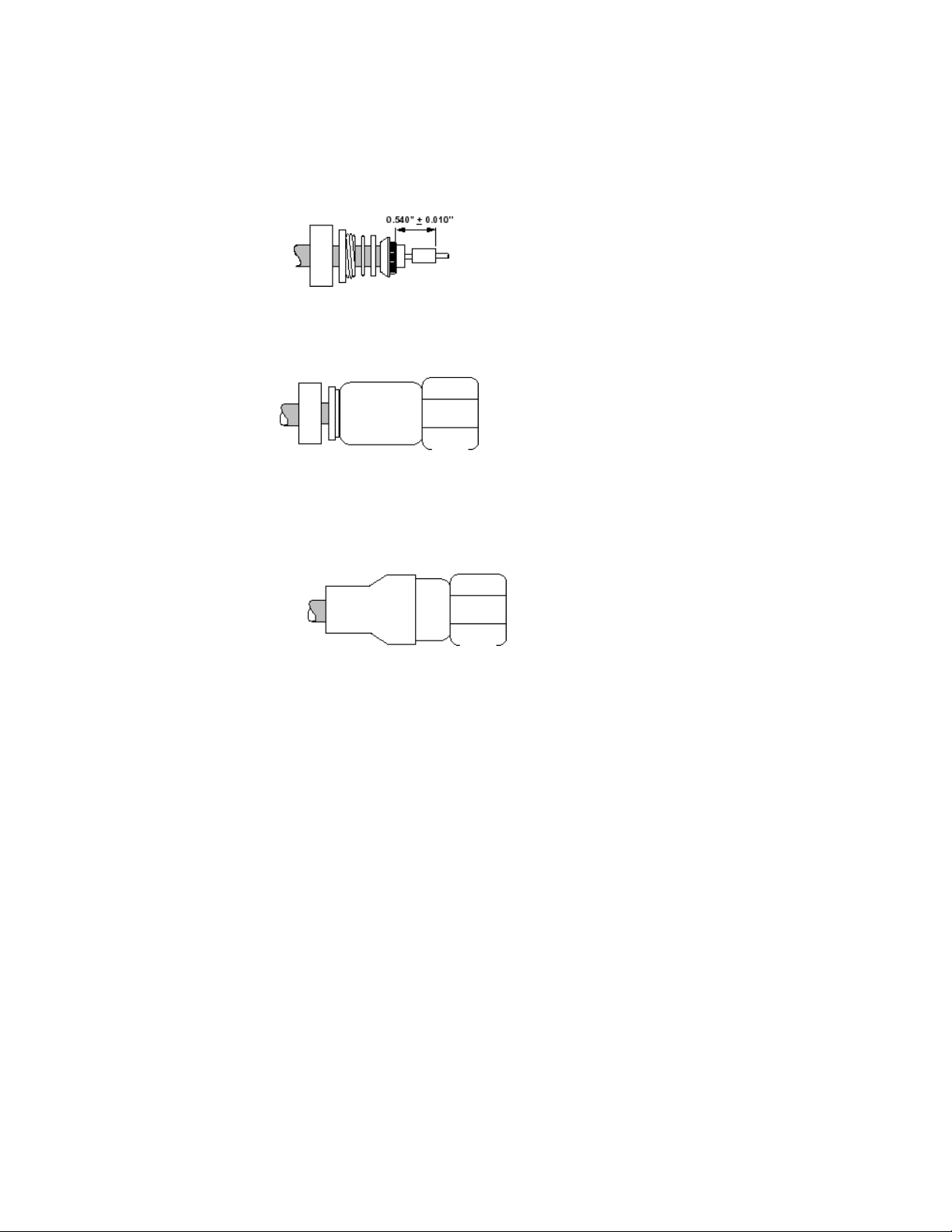
6 Install the contact. Solder on the contact using 60/40 solder. Feed solder through solder hole while
heating the contact.
7 Install the connector body onto the cable. Check for proper pin height. Apply Locktite 242 to the clamp nut
threads. Thread the clamp nut into the connector body. Torque to 50 in-lbs. Check pin height.
8 Install strain relief boot. Position the boot onto the connector body. Apply hot air until boot is smoothly
seated onto both the cable and connector. Use only an adhesive lined shrink boot.
34
01-0945-401 Rev. A 08/2004
Page 45

Appendix C
Outdoor Unit Recommendations
For TX IFL cable lengths less than those listed in the following table, an in-line attenuator should be inserted into
the cable. ComStream recommends the use of a Radyne ComStream attenuator, part number 17-0107-101. The
attenuator ensures a minimum dynamic range of 15 dB in the output power.
The minimum cable length should be used as a guide by the system integrators and installers as an approximation
only.
The maximum cable length is 100 meters in all installations.
Radyne ComStream strongly recommends the use of Times Microwave LMR-400 TX IFL cable and Times Fiber
RG11 quad-shielded Rx cable. For information on ordering LMR-400 or RG-11 cable, refer to the appendix on
cable specifications.
The following table provides the recommended Outdoor Unit:
Output Power
Watt dBm
2 33 Ku 30-0120-510 20
4 36 Ku 30-0120-560 20
5 37 C 30-0120-479 45
8 39 Ku 30-0120-584 20
10 40 C 30-0120-583 20
For additional information and updates regarding outdoor units, contact your Radyne ComStream sales
representative.
Frequency
Band
ODU Part Number Minimum IFL
Cable Length
(meters)
35
01-0945-401 Rev. A 08/2004
Page 46

Glossary
A
AC Alternating Current
AGC Automatic Gain Control
ANSI American National Standards Institute
AO Acquisition Offset
ARP Address Resolution Protocol
ASCII American Standard Code for Information Interchange
ASIC Application Specific Integrated Circuit
ATE Automatic Test Equipment
B
G
BER Bit Error Rate
BERT Bit Error Rate Test
Bit/BIT Binary Digit or Built-In Test
bps Bits Per Second
BPSK Binary Phase Shift Keying
Bridge Interconnects LAN segments at the network interface layer level
BUC Block Upconverter
Byte 8 Binary Digits
36
01-0945-401 Rev. A 08/2004
Page 47

C
C Celsius
CA/xxxx Cable Assembly
CD-ROM Compact Disk – Read Only Memory
CLK Clock
cm Centimeter
COM Common
CPU Central Processing Unit
D
DD Differential Decoding
Default
Gateway
DFS Demod Filter Select
DC Direct Current
Demod Demodulator or Demodulated
DVB Digital Video Broadcast
Eb/N0 Ratio of Energy per bit to Noise Power Density in a 1 Hz Bandwidth.
EBT Eb/No Threshold
EIA Electronic Industries Association
Used where one or more routers exist
E
37
01-0945-401 Rev. A 08/2004
Page 48

F
FEC Forward Error Correction
FW Firmware
G
GHz Gigahertz
GND Ground
H
HDLC High-level Data Link Control
HW Hardware
Hz Hertz (Unit of Frequency)
I
IEEE International Electrical and Electronic Engineers
IF Intermediate Frequency
IP Internet Protocol
ISO International Standards Organization
J
38
01-0945-401 Rev. A 08/2004
Page 49

K
Kbps Kilobits per Second
Kbps Kilobytes per Second
kg Kilogram
kHz Kilohertz
Ksps Kilosymbols per Second
L
LCD Liquid Crystal Display
LED Light Emitting Diode
LNB Low Noise Block Amplifier
M
MAC Message Authentication Code
Mbps Megabits per Second
MHz Megahertz
Mod Modulator or Modulated
MPEG Moving Pictures Experts Group
Multicast If an IP datagram is broadcast to a subnet, it is received by every host on the
subnet.
M&C Monitor and Control
N
NMS Network Management System
O
ODU Outdoor Unit
P
PC Pure Carrier
PCR Programmable Clock Reference
PID Program Identifier
P/N Part Number
Q
QPSK Quadrature Phase Shift Keying
R
RAD What does this mean?
RF Radio Frequency
RM Receive Modulation
39
01-0945-401 Rev. A 08/2004
Page 50

Router Interconnects networks at the inter-network layer level and routes packets
between them.
RR Receive Symbol Rate
RU Rack Unit. 1 RU = 1.75”/4.45 cm
Rx Receive (Receiver)
RxD Receive Data
S
SCPC Single Channel Per Carrier
Static Route Manual routing performed by the network administrator
Subnet Mask Identifier used in conjunction with an IP address for forwarding purposes
SYNC Synchronize
T
TCP Transmission Control Protocol
TCP/IP Transmission Control Protocol / Internet Protocol
Tx Transmit (Transmitter)
TxD Transmit Data
UDP User Datagram Protocol
V Volts
VAC Volts, Alternating Current
VCO Voltage Controlled Oscillator
VDC Volts, Direct Current
U
V
40
01-0945-401 Rev. A 08/2004
Page 51

W X Y Z
W Watt
Misc.
16QAM 16 Quadrature Amplitude Modulation
8PSK 8 Phase Shift Keying
41
01-0945-401 Rev. A 08/2004
 Loading...