

Page 1

HPCST-5000/-7000
HPKST-12000
HIGH-POWER TWTA
HIGH-POWER TWTA
HIGH-POWER TWTAHIGH-POWER TWTA
SATELLITE TERMINALS
SATELLITE TERMINALS
SATELLITE TERMINALSSATELLITE TERMINALS
Installation and Operation Manual
Installation and Operation Manual
Installation and Operation ManualInstallation and Operation Manual
Part Number MN/TWTA.I0M
Revision 1
Page 2

Page 3

EFData Corporation is an ISO 9001 Registered Company
HPCST-5000/-7000
HPCST-5000/-7000
HPCST-5000/-7000HPCST-5000/-7000
HPKST-12000
HPKST-12000
HPKST-12000HPKST-12000
HIGH-POWER TWTA
HIGH-POWER TWTA
HIGH-POWER TWTAHIGH-POWER TWTA
SATELLITE TERMINALS
SATELLITE TERMINALS
SATELLITE TERMINALSSATELLITE TERMINALS
Installation and Operation Manual
Installation and Operation Manual
Installation and Operation ManualInstallation and Operation Manual
Part Number MN/TWTA.I0M
Revision 1
March 28, 1998
Special Instructions:
Change bars were not utilized. For an overview of changes made to Rev. 0, refer to the preface
(“Overview of Changes to previous Edition”).
The revision supersedes part number MN/TWTA, Rev. 0 dated May 31,1997.
Copyright © EFData Corporation, 1998
All rights reserved.
Printed in the USA.
EFData Corporation, 2105 West 5th Place, Tempe, Arizona 85281 USA, (602) 968-0447, FAX: (602) 921-9012.
Page 4

Warranty Policy
This EFData Corporation product is warranted against defects in material and
workmanship for a period of one year from the date of shipment. During the warranty
period, EFData will, at its option, repair or replace produc t s that prove to be defective.
For equipment under warranty, the customer is responsible for f rei ght to EFData and
all related custom, taxes, tariffs, insurance, etc. EFData is responsible for the freight
charges
return the equipment by the same method (i.e., A i r, Express, Surface) as the
equipment was sent to EFDat a.
for return of the equipment f rom the factory to the c ustomer. EFData will
only
Limitations of Warranty
The foregoing warranty shall not apply to defects resulting from i mproper installation
or maintenance, abuse, unaut horized modification, or operat i on outside of
environmental specifi cations for the product, or, for damages that occ ur due to
improper repackaging of equipment for return to EFData.
No other warranty is expressed or implied. EFData Corporation specifically
disclaims the implied warranties of merchantability and fitness for particular
purpose.
Exclusive Remedies
The remedies provided herein are the buyer's sole and exclusive remedies. EF Dat a
Corporation shall not be liable for any direct, indirect, special, incidental, or
consequential damages, whether bas ed on contract, tort, or any ot her l egal theory.
Disclaimer
EFData has reviewed this manual thoroughly in order that it will be an easy-to-use
guide to your equipment. All statements, t echnical information, and recommendations
in this manual and in any guides or rel ated documents are believed reliabl e, but the
accuracy and completeness thereof are not guaranteed or warranted, and they are
not intended to be, nor should they be unders t ood to be, representations or warranties
concerning the products described. Further, EFData reserves the right to make
changes in the specifications of the products described in this manual at any time
without notice and without obligation to not i fy any person of such changes.
If you have any questions regarding your equipment or the information in this manual,
please contact the EFData Customer Support Department. (For more inform at i on,
refer to the preface.)
Page 5

About this Manual
This manual provides installation and operation information for the EFData high-power
Traveling Wave Tube (TWT) amplifier (TWTA) systems for EFData satellite terminal
systems. This is a technical document intended for earth station engineers, technicians,
and operators responsible for the operation and maintenance of the high-power TWTA
systems.
Conventions and References Used in this Manual
Cautions and Warnings
CAUTION indicates a hazardous situation that, if not avoided, may result in
minor or moderate injury. CAUTION may also be used to indicate other
CAUTION
unsafe practices or risks of property damage.
Preface
WARNING indicates a potentially hazardous situation that, if not avoided,
could result in death or serious injury.
WARNING
Trademarks
Product names mentioned in this manual may be trademarks or registered trademarks of
their respective companies and are hereby acknowledged.
Rev. 1 i
Page 6

Preface High-Power TWTA Satellite Terminals
Related Documents
The following documents are referenced in this manual:
• EFData CST-5000 C-Band Satellite Terminal Installation and Operation
Manual
• EFData CST-7000 C-Band Satellite Terminal (Insat) Installation and Operation
Manual
• EFData KST-12000 Ku-Band Satellite Terminal Installation and Operation
Manual
• EFData RSU-503 Redundancy Switch Unit Installation and Operation Manual
• IESS-309
Metric Conversions
Metric conversion information is located on the inside back cover of this manual. This
information will assist the operator in cross-referencing English to Metric conversions.
Reporting Comments or Suggestions Concerning this Manual
Comments and suggestions regarding the content and design of this manual will be
appreciated. To submit comments, please contact the EFData Customer Support
Department according to the following information.
Overview of Previous Editions
Changes made to Rev. 0 were:
Manual changed to reflect model number HPCST-5000/-7000 and HPKST -12000.
Incorporated new styles and profiles.
ii Rev. 1
Page 7

High-Power TWTA Satellite Terminals Preface
Customer Support
Contact the EFData Customer Support Department for:
• Product support
• Information on returning a product
• Information on upgrading a product
• Product training
• Reporting comments or suggestions concerning manuals
An EFData Customer Support representative may be reached at:
EFData Corporation
Attention: Customer Support Department
2105 West 5th Place
Tempe, Arizona 85281 USA
(602) 968-0447 (Main EFData Number)
(602) 370-7904 (24-Hour Customer Support Desk)
(602) 921-9012 FAX
or, E-Mail can be sent to the Customer Support Department at:
service@efdata.com
or, contact Customer Support Department at the web site
www.efdata.com
To return an EFData product (in-warranty and out-of-warranty) for repair or
replacement:
1. Request a Return Material Authorization (RMA) number from the EFData
Customer Support Department.
Be prepared to supply the Customer Support representative with the model
number, serial number, and a description of the problem.
2. To ensure that the product is not damaged during shipping, pack the product in
its original shipping carton/packaging.
3. Ship the product back to EFData. (Shipping charges should be prepaid.)
For more information regarding the warranty policies, refer to the disclaimer page
located behind the title page.
Rev. 1 iii
Page 8

Preface High-Power TWTA Satellite Terminals
This page is intentionally left blank.
iv Rev. 1
Page 9

Table of Contents
CHAPTER 1. INTRODUCTION..................................................................................1–1
1.1 Introduction...................................................................................................................................................... 1–2
1.2 Component Descriptions..................................................................................................................................1–7
1.2.1 Low-Noise Amplifier (LNA) Assembly ..................................................................................................... 1–7
1.2.2 Radio Frequency Terminal (RFT) .............................................................................................................. 1–7
1.2.3 TWTA Models............................................................................................................................................ 1–8
1.2.4 High-Power Controller (HPC) .................................................................................................................. 1–10
1.2.4.1 HPC-1200.......................................................................................................................................... 1–10
1.2.4.2 HPC-1110.......................................................................................................................................... 1–11
1.2.5 Redundant Switch Unit (RSU).................................................................................................................. 1–12
1.2 Equipment List ............................................................................................................................................... 1–13
1.3 Specifications.................................................................................................................................................. 1–17
1.3.1 System Interface ....................................................................................................................................... 1–17
1.3.2 Prime Power ............................................................................................................................................. 1–18
1.3.3 Performance.............................................................................................................................................. 1–19
1.3.3.1 Receive.............................................................................................................................................. 1–19
1.3.3.2 Transmit ............................................................................................................................................ 1–21
1.3.4 Environment............................................................................................................................................. 1–25
1.3.5 Monitor and Control................................................................................................................................. 1–26
1.3.6 Physical Size and Weight......................................................................................................................... 1–27
Rev. 1 v
Page 10

Table of Contents High-Power TWTA Satellite Terminals
CHAPTER 2. SINGLE THREAD SYSTEM INSTALLATION......................................2–1
2.1 Unpacking......................................................................................................................................................... 2–2
2.2 Inspecting the Equipment................................................................................................................................ 2–3
2.2.1 Included Parts............................................................................................................................................. 2–3
2.3 TWTA Installation........................................................................................................................................... 2–7
2.3.1 Tools Required ........................................................................................................................................... 2–8
2.3.2 Vertical Pole Installation ............................................................................................................................ 2–9
2.3.2.1 Round Pole.......................................................................................................................................... 2–9
2.3.2.2 Square Pole........................................................................................................................................ 2–13
2.3.3 Spar Installation ........................................................................................................................................ 2–14
2.3.4 External Connections................................................................................................................................ 2–16
2.3.4.1 TWTA Monitor & Control (J1)......................................................................................................... 2–18
2.3.4.1.1 Control Interfaces....................................................................................................................... 2–20
2.3.4.1.2 Digital Status Circuits................................................................................................................ 2–21
2.3.4.1.3 Analog Status Circuits................................................................................................................ 2–23
2.3.4.1.4 Output Voltage Circuits............................................................................................................. 2–24
2.3.4.1.5 Control/Status Ground Isolation................................................................................................ 2–24
2.3.4.2 TWTA Prime Power (J2) .................................................................................................................. 2–25
2.3.4.2.1 Prime Power............................................................................................................................... 2–25
2.3.4.3 RF TX Input (J3)............................................................................................................................... 2–26
2.3.4.4 RF TX Sample (J4) ........................................................................................................................... 2–27
2.3.4.5 RF Output (J5)................................................................................................................................... 2–27
2.3.4.6 Waveguide......................................................................................................................................... 2–27
2.3.4.7 System Interface Wiring.................................................................................................................... 2–28
2.4 HPC-1200 Installation................................................................................................................................... 2–30
2.4.1 Mechanical................................................................................................................................................ 2–30
2.4.2 External Connections................................................................................................................................ 2–31
2.4.2.1 External Interfaces (J1) ..................................................................................................................... 2–31
2.4.2.1.1 Control Interfaces....................................................................................................................... 2–33
2.4.2.1.2 Digital Status Circuits................................................................................................................ 2–33
2.4.2.1.3 Analog Status Circuits................................................................................................................ 2–35
2.4.2.1.4 Output Voltage Circuits............................................................................................................. 2–35
2.4.2.2 ODU Monitor and Control (J2)......................................................................................................... 2–36
2.4.2.3 Prime Power...................................................................................................................................... 2–36
CHAPTER 3. REDUNDANT SYSTEM INSTALLATION............................................3–1
3.1 Unpacking......................................................................................................................................................... 3–2
3.2 Inspecting the Equipment................................................................................................................................ 3–3
3.2.1 Included Parts............................................................................................................................................. 3–3
3.3 TWTA Installation........................................................................................................................................... 3–9
3.3.1 Tools Required ......................................................................................................................................... 3–10
3.3.2 Vertical Pole Installation .......................................................................................................................... 3–11
3.3.2.1 Round Pole........................................................................................................................................ 3–11
3.3.2.2 Square Pole........................................................................................................................................ 3–14
3.3.3 Spar Mount............................................................................................................................................... 3–14
vi Rev. 1
Page 11

High-Power TWTA Satellite Terminals Table of Contents
3.3.4 External Connections................................................................................................................................ 3–15
3.3.4.1 System Interface Wiring.................................................................................................................... 3–15
3.4 HPC-1110 Installation................................................................................................................................... 3–23
3.4.1 Mechanical................................................................................................................................................ 3–23
3.4.1.1 Cabinet Slide Assembly..................................................................................................................... 3–25
3.4.2 External Connections................................................................................................................................ 3–27
3.4.2.1 Standard Connections........................................................................................................................ 3–28
3.4.2.1.1 AC Prime Power........................................................................................................................ 3–28
3.4.2.1.2 TWTA Serial Interface ..............................................................................................................3–29
3.4.2.1.3 External Interlock/Remote Functions......................................................................................... 3–29
3.4.2.1.4 Waveguide Switch #1 ................................................................................................................ 3–29
3.4.2.1.5 Waveguide Switch #2 ................................................................................................................ 3–29
3.4.2.1.6 Remote Control Serial Interface................................................................................................. 3–30
3.4.2.2 “X” Insert Panel Connectors............................................................................................................. 3–32
3.4.2.2.1 Auxiliary Interface..................................................................................................................... 3–32
3.4.2.3 “X” Insert Panel Configurations........................................................................................................ 3–33
3.4.2.4 “Y” Insert Panel Connectors............................................................................................................. 3–34
CHAPTER 4. TWT AMPLIFIERS...............................................................................4–1
4.1 Operation and Control.................................................................................................................................... 4–2
4.1.1 Control and Status Interface....................................................................................................................... 4–2
4.1.2 Operating Modes........................................................................................................................................ 4–2
4.1.2.1 Heater Delay........................................................................................................................................ 4–2
4.1.2.2 Heater Standby.................................................................................................................................... 4–3
4.1.2.3 Standby................................................................................................................................................ 4–3
4.1.2.4 High Voltage ON................................................................................................................................. 4–3
4.1.2.5 Fault..................................................................................................................................................... 4–4
4.1.2.5.1 Clearing Faults............................................................................................................................. 4–5
4.1.3 Control and Status Signals.......................................................................................................................... 4–5
4.1.3.1 Control................................................................................................................................................. 4–5
4.1.3.2 Digital Status....................................................................................................................................... 4–6
4.1.3.3 Analog................................................................................................................................................. 4–7
4.1.4 Initial Power-Up......................................................................................................................................... 4–8
4.1.4.1 Pre-Power Check................................................................................................................................. 4–8
4.1.4.2 Power-On Sequence............................................................................................................................ 4–9
4.1.5 Shut Down.................................................................................................................................................. 4–9
4.2 Maintenance and Service............................................................................................................................... 4–10
4.2.1 Preventive Maintenance............................................................................................................................ 4–10
CHAPTER 5. CONTROLLER FOR SINGLE THREAD SYSTEMS............................5–1
5.1 Operation.......................................................................................................................................................... 5–2
5.1.1 LOCAL Control Configuration................................................................................................................... 5–3
5.1.2 REMOTE Control Configuration............................................................................................................... 5–3
5.1.3 Controls and Indicators............................................................................................................................... 5–3
Rev. 1 vii
Page 12

Table of Contents High-Power TWTA Satellite Terminals
5.2 Maintenance and Service................................................................................................................................. 5–9
5.2.1 Preventative Maintenance........................................................................................................................... 5–9
5.2.2 Operator Troubleshooting........................................................................................................................... 5–9
5.2.3 Clearing a Fault.........................................................................................................................................5–10
5.2.3.1 Clearing a Fault-LOCAL Control Configuration.......................................................................... ..... 5–10
5.2.3.2 Clearing a Fault-REMOTE Control Configuration ........................................................................... 5–10
CHAPTER 6. CONTROLLER FOR REDUNDANT SYSTEMS ..................................6–1
6.1 Overview........................................................................................................................................................... 6–2
6.1.1 “X” Insert and “Y” Insert Panels ................................................................................................................ 6–2
6.2 Operation.......................................................................................................................................................... 6–3
6.2.1 User Operational Choices........................................................................................................................... 6–3
6.2.1.1 Warm-Standby or Hot-Standby........................................................................................................... 6–3
6.2.1.2 Manual or Automatic Switching.......................................................................................................... 6–4
6.2.2 Local Controls and Indicators..................................................................................................................... 6–4
6.2.2.1 Basic Controls and Indicators.............................................................................................................. 6–4
6.2.2.1.1 Power Indicator............................................................................................................................ 6–5
6.2.2.1.2 Local/Remote Push Button Switch............................................................................................... 6–5
6.2.2.1.3 Manual/Automatic Push Button Switch....................................................................................... 6–6
6.2.2.1.4 HV ON Push Button Switch......................................................................................................... 6–7
6.2.2.1.7 Waveguide Switch Position Indicators......................................................................................... 6–8
6.2.2.1.8 Fault Reset Push Button Switch................................................................................................... 6–8
6.2.2.1.9 Lamp Test Push Button Switch.................................................................................................... 6–8
6.2.3 TWTA Setup for Redundant System Operation ......................................................................................... 6–9
6.2.3.1 Remote Controller Mode..................................................................................................................... 6–9
6.2.3.2 Local Controller Mode........................................................................................................................ 6–9
6.2.4 Initial Power-On......................................................................................................................................... 6–9
6.2.5 Normal Operation..................................................................................................................................... 6–10
APPENDIX A. PROGRAMMING GUIDE FOR REDUNDANT CONTROLLER......... A–1
A.1 Overview..........................................................................................................................................................A–1
A.1.1 Communication Protocols ..........................................................................................................................A–2
A.2 Communication Protocols..............................................................................................................................A–3
A.2.1 Command Message Format........................................................................................................................A–3
A.2.1.1 Header and Ending Byte.....................................................................................................................A–3
A.2.1.2 Primary Address Byte.........................................................................................................................A–4
A.2.1.3 Secondary Address Byte.....................................................................................................................A–4
A.2.1.4 Command Byte...................................................................................................................................A–4
A.2.1.5 Parameters..........................................................................................................................................A–4
A.2.1.6 Check Byte.........................................................................................................................................A–5
A.2.1.7 Parity .................................................................................................................................................. A–5
A.2.2 Response Message Format.........................................................................................................................A–6
A.2.2.1 Header and Ending Byte.....................................................................................................................A–6
A.2.2.2 Address Byte......................................................................................................................................A–6
A.2.2.3 Response Byte .................................................................................................................................... A–6
A.2.2.4 Parameters..........................................................................................................................................A–6
A.2.2.5 Check Byte.........................................................................................................................................A–6
A.2.2.6 Parity .................................................................................................................................................. A–7
viii Rev. 1
Page 13

High-Power TWTA Satellite Terminals Table of Contents
A.2.2.7 Command Reject Argument ...............................................................................................................A–7
A.2.3 ASCII Reference Information....................................................................................................................A–8
A.3 Redundant System Command Set................................................................................................................A–10
A.3.1 Controller Query Commands...................................................................................................................A–11
A.3.2 Controller Control Commands.................................................................................................................A–13
A.4 TWTA Command Set....................................................................................................................................A–15
A.4.1 TWTA Query Commands........................................................................................................................A–15
A.4.2 TWTA Control Commands......................................................................................................................A–17
GLOSSARY .................................................................................................................g-1
INDEX ...........................................................................................................................i-1
Rev. 1 ix
Page 14

Table of Contents High-Power TWTA Satellite Terminals
Figures
Figure 1-1. HPCST-5000/-7000 and HPKST-12000............................................................................................... 1–1
Figure 1-2. TWTA Redundant Assembly (Typical)................................................................................................. 1–3
Figure 1-3. HPCST-5000/-7000 Redundant Terminal Systems Block Diagram (Typical)...................................... 1–5
Figure 1-4. HPKST-12000 Redundant Terminal System Block Diagram (Typical)................................................ 1–6
Figure 1-5. 100W and 140W Unit Block Diagram.................................................................................................. 1–9
Figure 1-6. 300W and 350W Unit Block Diagram.................................................................................................. 1–9
Figure 1-7. HPC-1200 Single Thread Controller................................................................................................... 1–10
Figure 1-8. HPC-1110 1:1 Redundant Controller.................................................................................................. 1–11
Figure 1-9. RSU-503L........................................................................................................................................... 1–12
Figure 1-10. TWTA Outline Drawing (Typical).................................................................................................... 1–28
Figure 1-11. HPC-1200 Outline Drawing.............................................................................................................. 1–29
Figure 1-12. HPC-1110 Outline Drawing.............................................................................................................. 1–30
Figure 2-1. Typical TWTA Spar Installation......................................................................................................... 2–14
Figure 2-2. 100W and 140W TWTA External Connections.................................................................................. 2–16
Figure 2-3. 300W and 350W TWTA External Connections.................................................................................. 2–17
Figure 2-4. Interface Connector Pinouts ................................................................................................................ 2–19
Figure 2-5. TWT Temperature: Temperature vs. Voltage ..................................................................................... 2–23
Figure 2-6. Single Phase AC Power Connections................................................................................................. 2–26
Figure 2-7. Single Thread System M&C Cable Harness (CA/5124)...................................................................... 2–29
Figure 2-8. HPC-1200 Outline Drawing................................................................................................................ 2–30
Figure 2-9. HPC-1200 Rear Panel Connector Locations ....................................................................................... 2–31
Figure 2-10. Interface Connector Pinouts ...................................................................................... ........................ 2–32
Figure 2-11. Digital Status Circuit Isolation ..........................................................................................................2–33
Figure 3-1. HPCST/HPKST 1:1 Redundant System Cable Harness (CA/5122) .................................................... 3–16
Figure 3-2. HPCST/KST 1:1 Redundant M&C System Interface Cable (Optional) (CA/5279)............................ 3–18
Figure 3-3. HPCST/HPKST 1:1 Uplink-Only Redundant System Cable Harness (CA/5248)............................... 3–20
Figure 3-4. HPCST/HPKST HPCST/HPKST Single TWTA System Cable Harness (CA/5124)......................... 3–22
Figure 3-5. HPC-1110 Outline Drawing................................................................................................................ 3–24
Figure 3-6. Cabinet Slide Assemblies.................................................................................................................... 3–26
Figure 3-7. HPC-1110 rear Panel........................................................................................................................... 3–27
Figure 3-8. Prime Power Connector....................................................................................................................... 3–28
Figure 3-9. Waveguide Switch Connector Pinouts................................................................................................. 3–29
Figure 3-10. EIA-422, -485 Pinouts, COM2 Only................................................................................................. 3–31
Figure 3-11. EIA-232-C Pinouts............................................................................................................................ 3–32
Figure 3-12. Auxiliary interface Connector Pinouts............................................................................................... 3–33
Figure 3-13. “X” Insert Configuration ................................................................................................................... 3–34
Figure 3-14. Configuration 1, “X” Insert Panel...................................................................................................... 3–34
Figure 5-1. HPC-1200.............................................................................................................................................. 5–1
Figure 5-2. Typical Configuration............................................................................................................................ 5–2
Figure 5-3. Monitor Points and Lamp Test.............................................................................................................. 5–4
Figure 5-4. Fault Indicators...................................................................................................................................... 5–5
Figure 5-5. Status Indicators.................................................................................................................................... 5–6
Figure 5-6. HPC-1200 Local Controls..................................................................................................................... 5–7
Figure 5-7. TEMP ANALOG Output Calibration.................................................................................................... 5–8
Figure 6-1. HPC-1110.............................................................................................................................................. 6–1
Figure 6-2. Basic HPC-1110 Rear Panel.................................................................................................................. 6–2
x Rev. 1
Page 15

High-Power TWTA Satellite Terminals Table of Contents
Tables
Table 1-1. Major Assemblies of the HPCST-5000/-7000........................................................................................ 1–2
Table 1-2. Major Assemblies of the HPKST-12000................................................................................................ 1–3
Table 1-3. TWTA Models........................................................................................................................................ 1–8
Table 1-4. Description of the HPC-1200............................................................................................................... 1–10
Table 1-5. Description of the HPC-1110............................................................................................................... 1–11
Table 1-6. HPCST-5000/–7000 Single Thread Systems Equipment List (Typical)............................................... 1–13
Table 1-7. HPKST-12000 Single Thread System Equipment List (Typical)......................................................... 1–15
Table 1-8. HPKST-12000 Redundant System Equipment List (Typical) .............................................................. 1–16
Table 1-9. System Interfaces for System Components........................................................................................... 1–17
Table 1-10. Prime Power ....................................................................................................................................... 1–18
Table 1-11. HPCST-5000/–7000 Receive Characteristics..................................................................................... 1–19
Table 1-12. HPKST-12000 Receive Characteristics............................................................................................. 1–20
Table 1-13. HPCST-5000 and -7000 Transmit Characteristics.............................................................................. 1–21
Table 1-14. HPA-500, -700 Transmit Characteristics............................................................................................ 1–22
Table 1-15. HPKST-12000 Transmit Characteristics ............................................................................................ 1–23
Table 1-16. HPA-1200 Transmit Characteristics................................................................................................... 1–24
Table 1-17. ODU Environmental Specifications.................................................................................................... 1–25
Table 1-18. IDU Environmental Specifications..................................................................................................... 1–25
Table 1-19. Monitor and Control........................................................................................................................... 1–26
Table 1-20. Physical Size and Weight Characteristics........................................................................................... 1–27
Table 2-1. External Connections............................................................................................................................ 2–16
Table 2-2. TWTA Monitor & Control Pinouts ...................................................................................................... 2–18
Table 2-3. Prime Power ......................................................................................................................................... 2–25
Table 2-4. Mating Connector for AC Unit............................................................................................................. 2–26
Table 2-5. Rear Panel Connectors.......................................................................................................................... 2–31
Table 2-6. Remote Control Interface Connector Pinouts....................................................................................... 2–32
Table 2-7. M&C Connector Pinouts...................................................................................................................... 2–36
Table 5-1. Monitor Point and Lamp Test Descriptions............................................................................................ 5–3
Table 5-2. Fault Indicator Descriptions.................................................................................................................... 5–5
Table 5-3. Status Indicator Desvcriptions................................................................................................................ 5–6
Table 5-4. HPC-1200 Local Control Descriptions................................................................................................... 5–7
Table 6-1. HPC-1110 Local Functions..................................................................................................................... 6–4
Table 6-2. Local/Remote Modes.............................................................................................................................. 6–5
Table 6-3. Manual/Automatic Mode........................................................................................................................ 6–6
Table 6-4. HV ON Push Button Switch................................................................................................................... 6–7
Table A-1. Header Byte Codes................................................................................................................................A–1
Table A-2. Command Not Executed Codes............................................................................................................. A-7
Table A-3. ASCII Cross Reference..........................................................................................................................A–8
Table A-4. Meaning of Multi-Character ASCII Codes............................................................................................A–9
Table A-5. Redundant System Controller Query Commands.................................................................................A–11
Table A-6. Redundant Sytem Controller Control Commands................................................................................A–13
Table A-7. TWTA Query Commands....................................................................................................................A–15
Table A-8. TWTA Control Commands..................................................................................................................A–17
Rev. 1 xi
Page 16

Table of Contents High-Power TWTA Satellite Terminals
This page is intentionally left blank.
xii Rev. 1
Page 17

Chapter 1.
INTRODUCTION
1
This chapter provides an overview of the Traveling Wave Tube Amplifier (TWTA)
coupled with various components:
• HPCST-5000 high-power C-band satellite terminal (Figure 1-1)
• HPCST-7000 high-power extended C-band satellite terminal (Figure 1-1)
• HPKST-12000 high-power Ku-band satellite terminal (Figure 1-1)
Figure Chapter 1-1. HPCST-5000/-7000, and HPKST-12000
Rev. 1 1–1
Page 18

Introduction High-Power TWTA Satellite Terminals
1.1 Introduction
The key component of these high-power systems is the external high-power TWTA.
When the TWTA is coupled with the CST-5000/-7000, and KST-12000 satellite terminal
systems, these components form an integrated high-power transceiver system. These
all-weatherized units are designed for the harsh, uncontrolled, outdoor environment
typical of antenna mounting. These completely integrated systems meet the requirements
for private, regional domestic, and international C-band or Ku-band satellite networks.
All three products may be configured for single thread or 1:1 redundant systems.
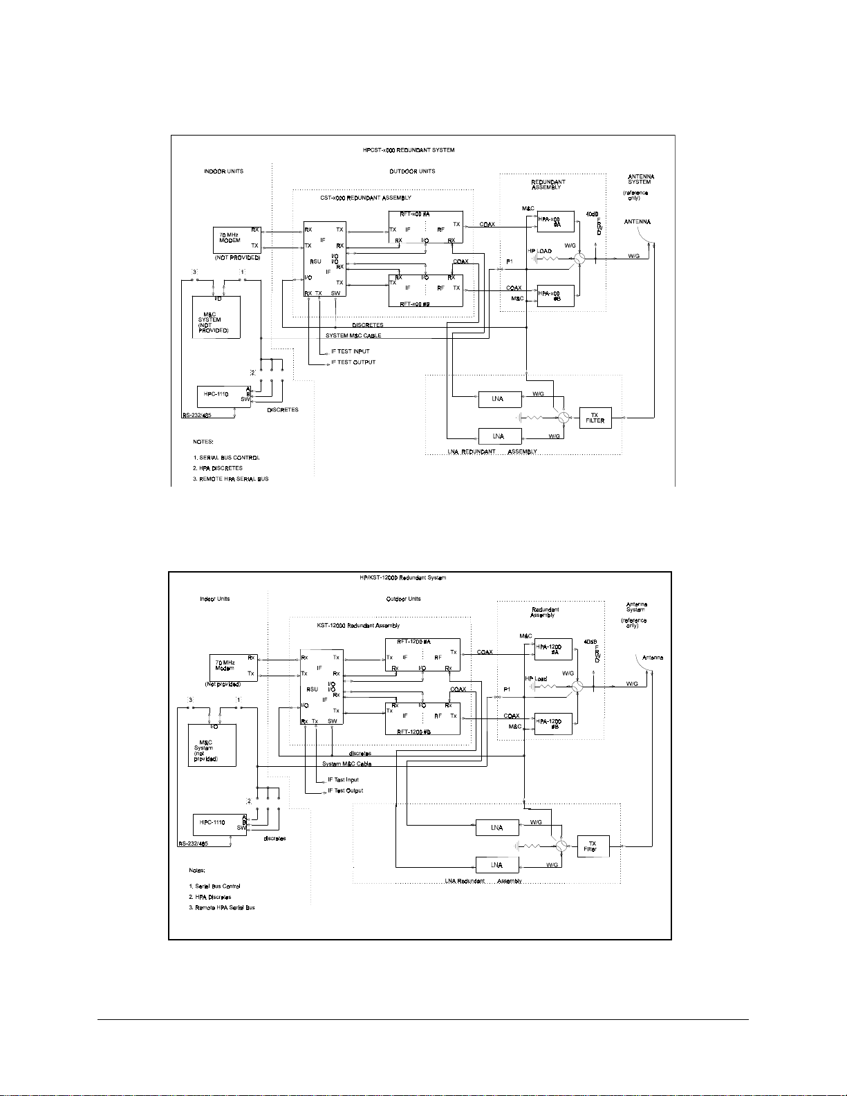
Refer to Table Chapter 1-1 for a typical HPCST-5000 and -7000 redundant system.
Table Chapter 1-1. Major Assemblies of the HPCST-5000/-7000
Nomenclature Description
Outdoor Low-Noise Amplifier (LNA) Ass y Consists of a transit reject filter, redundant LNAs
(65°K; 40°K Optional) and a C-Band waveguide
switch.
Outdoor HPCST-5000/HPCST-7000 R e dunda nt
Assy
Outdoor high-power T W TA Redundant Ass y
(Figure Chapter
HPS-1110 An optional indoor, rack- mounted, redundant
Redundancy Sw itch U nit (R SU ) Along with a redunda nc y cable/hardware k it,
1-2
)
Consists of two ra dio frequency term ina ls (R FT s )
assemblies. Each RFT includes an up converter
with a 70 MHz IF input, a dow n c onv e rte r with a
70 MHz IF output, a monitor and c ontrol (M& C )
microproces s or, a nd a power supply.
Consists of two hig h-power TWTAs , a waveguide
switch, an output coupler, and a s ystem cable
harness with a customer-interface connector for
system control.
TWTA controlle r. Allows the customer M&C of
TWTAA operations.
provides the system with a single M&C interface,
redundancy switchover, and cabling.
1–2 Rev. 1
Page 19

High-Power TWTA Satellite Terminals Introduction
Figure Chapter 1-2. TWTA Redundant Assembly (Typical)
Refer to Table Chapter 1-2 for a typical HPKST-12000 redundant system.
Table Chapter 1-2. Major Assemblies of the HPKST-12000
Nomenclature Description
Outdoor LNA A ss y
Outdoor KST-12000 Redunda nt
Assy
Outdoor TWTA R e dunda nt Assy
(Figure 1-2)
HPS-1110 An optional indoor, rack-mounted, redundant TWTA controller.
Redundancy Sw itc h Unit (R SU ) Along with a redunda nc y cable/hardware k it, provides the system
Consists of a transit reject f ilte r, re dundant LNAs (120°K; 90°K
Optional) and a
Ku-Band waveguide sw itc h. Optiona lly, a Ku-Band coaxial
switch, 1:4 power splitter, and frequency (block) conv e rte r a re
available.
Consists of two RFT-12000 redundant assemblie s. Eac h R FT
includes an up converte r with a 70 MHz IF input, a down
converter with a 70 MHz I F output, a n M&C microprocessor,
and a power supply.
Consists of two high- power TWTAs, a waveguide switch, a n
output coupler, and a sys te m cable harness with a c us tomerinterface connector for sys te m control.
Allows the cust omer M&C of TWTAA operations.
with a single M&C interface, redundancy switchove r , a nd
cabling.
Rev. 1 1–3
Page 20

Introduction High-Power TWTA Satellite Terminals
The system outdoor terminal components are weatherproof units for the uplink and
downlink requirements. The redundant assemblies have been designed for antenna or
pole mounting. The system has a single customer interface connector for remote monitor
and control.
The onboard microcomputer monitors and controls the operational parameters. This
M&C system enables the user to locally or remotely control functions such as:
• Output power level
• Output On/Off
• Transmit/Receive channel frequency
The system also reports terminal configuration status, as well as fault status of all
components. The RFT can be initially configured by a keyboard/LCD controller within
the enclosure, or by connection of a common ASCII/EIA-232 terminal connected to the
serial port at the system interface connector (P1). A simple command set allows
configuration control and retrieval of status information.
If the customer M&C control unit is a more sophisticated monitor and control station
computer, the serial port can be set to EIA-485 for bus operation. A separate,
rack-mounted, redundant controller for the TWTAs provides the user with control and
status of the TWTA operation, as well as an automatic high voltage enable for
switchover.
Refer to Figure Chapter 1-3 for a system block diagram of the HPCST-5000/-7000
redundant systems.
Refer to Figure 1-4 for a system block diagram of the HPKST-12000 redundant systems.
1–4 Rev. 1
Page 21
High-Power TWTA Satellite Terminals Introduction
Figure Chapter 1-3. HPCST-5000/7000 Redundant Terminal Systems Block
Diagram (Typical)
Figure Chapter 1-4. KST-12000 Redundant Terminal System Block Diagram (Typical)
Rev. 1 1–5
Page 22

Introduction High-Power TWTA Satellite Terminals
1.2 Component Descriptions
1.2.1 Low-Noise Amplifier (LNA) Assembly
A typical redundant LNA assembly consists of a transmit reject filter, waveguide switch,
and two LNAs. Optionally, a coaxial switch, 1:4 power splitter, and a block converter are
available.
For more information on the LNA assemblies, refer to the following manuals:
• CST-5000 C-Band Satellite Terminal Installation and Operation Manual
• CST-7000 C-Band Satellite Terminal (Insat) Installation and Operation Manual
• KST-12000 Ku-Band Satellite Terminal Installation and Operation Manual
1.2.2 Radio Frequency Terminal (RFT)
The RFT is a weatherproof enclosure which houses:
• Up and down converters
• Frequency synthesizer
• IF and RF interface
• M&C system
• Power supply
• Cables
In the transmit (uplink) direction, the terminal accepts a 70 MHz IF signal and transmits
it in the uplink transmit frequency band. This output is coupled through a type N
connector to the external TWTA assembly. This system provides the high-power output
to the antenna through a waveguide switch. A 40 dB coupler is included at the output of
the waveguide switch to meet INTELSAT specifications.
A high-power termination is included on the offline channel port of the waveguide
switch for testing. Each redundant thread has been factory-compensated for TX gain
stability over temperature. EFData recommends that when replacing a faulted unit, the
RFT, TWTA, and associated coax link must be replaced as a set. Otherwise, gain
stability can not be guaranteed.
In the receive (downlink) direction, the terminal accepts an RF signal in the downlink
frequency band, and down-converts it to a 70 MHz IF output. The LNA assembly has an
RF RX type N coax output to each RFT receive input.
1–6 Rev. 1
Page 23

High-Power TWTA Satellite Terminals Introduction
The RFT power level at 1 dB compression to drive the external TWTA is +8 dBm. The
up and down converters are dual conversion, and are configured with individual
synthesizers for independent transmit and receive transponder selection.
For more information on RFTs, refer to the following manuals:
• CST-5000 C-Band Satellite Terminal Installation and Operation Manual
• CST-7000 C-Band Satellite Terminal (INSAT) Installation and Operation
Manual
• KST-12000 Ku-Band Satellite Terminal Installation and Operation Manual
1.2.3 TWTA Models
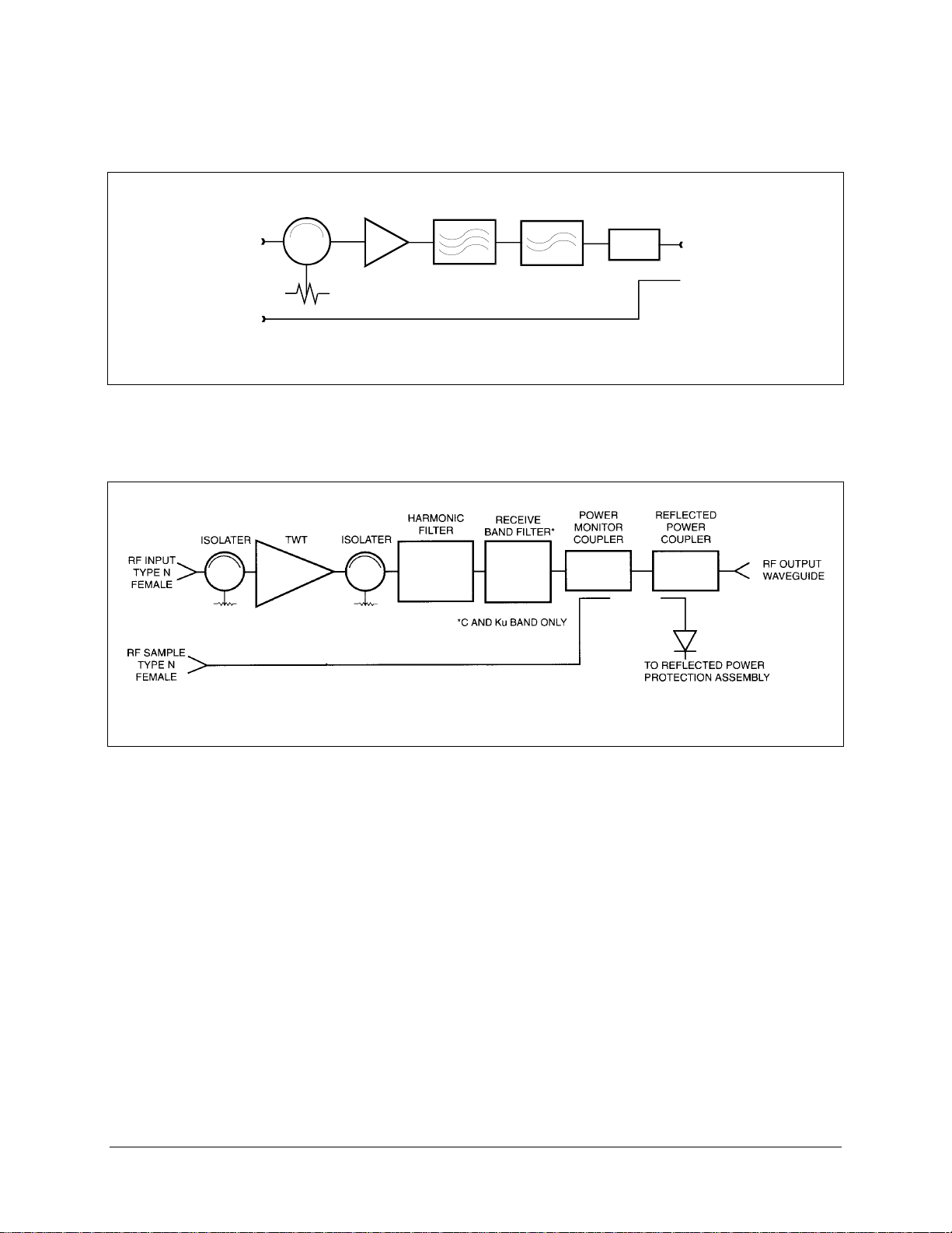
The TWTA is an all-weather, high-power system specifically designed for compact
outdoor installation for earth station satellite communication. Because of the
compactness, the unit can be mounted on the antenna, thus reducing transmission losses
to the antenna feed. This outdoor unit contains:
• RF filters
• Self-contained forced air cooling system
• Control inputs
• Monitor output signals
EFData offers six TWTA models that operate in the satellite earth station uplink bands.
Specific models and options are identified by the EFData part number in Table 1-3.
Table Chapter 1-3. TWTA Models
Band Model # EFData
Part #
C-Band HPA-500
HPA-500
HPA-700
HPA-700
Ku-Band HPA-1200
HPA-1200
Note:
Manufacturing changes which do not impact component interchangability are
RF/XT-100C
RF/XT-400C
RF/XT-100CI
RF/XT-400CI
RF/XT-100K
RF/XT-400K
Frequency Rated RF
5.845 to 6.425 GHz
5.845 to 6.425 GHz
7.9 to 8.4 GHz
7.9 to 8.4 GHz
14.0 to 14.5 GHz
14.0 to 14.5 GHz
Power (Min.)
140W
350W
140W
350W
100W
300W
reflected in the revision level of the power amplifier part number. EFData maintains a
configuration log by serial number to track the applicable revision level for each power
amplifier. Please include the amplifier serial number when ordering parts or discussing
the amplifier with EFData representatives.
Prime input power to the unit is AC, as follows:
• 115 or 230VAC for the 100W unit
Rev. 1 1–7
Page 24

Introduction High-Power TWTA Satellite Terminals
• 100 to 260VAC for the 350W unit.
• Refer to Figures 1-5 and 1-6 for block diagrams.
1–8 Rev. 1
Page 25
High-Power TWTA Satellite Terminals Introduction
RECEIVE
POWER
RF INPUT
TYPE N
FEMA LE
RF SAMPLE
TYPE N
FEMALE
ISOLAT E R
TW T
HARMONIC
FILTER
BAND
FILTER*
MONITOR
COUPLER
*C AND Ku BAND O NLY
Figure Chapter 1-5. 100W and 140W Unit Block Diagram
RF OUTPUT
WAVEGUIDE
Figure Chapter 1-6. 300W and 350W Unit Block Diagram
Rev. 1 1–9
Page 26
Introduction High-Power TWTA Satellite Terminals
1.2.4 High-Power Controller (HPC)
The optional HPCs are indoor rack-mounted units used to monitor and control the status
of the TWTA units in the HPCST–5000/–7000, and HPKST–12000 high-power satellite
terminal systems.
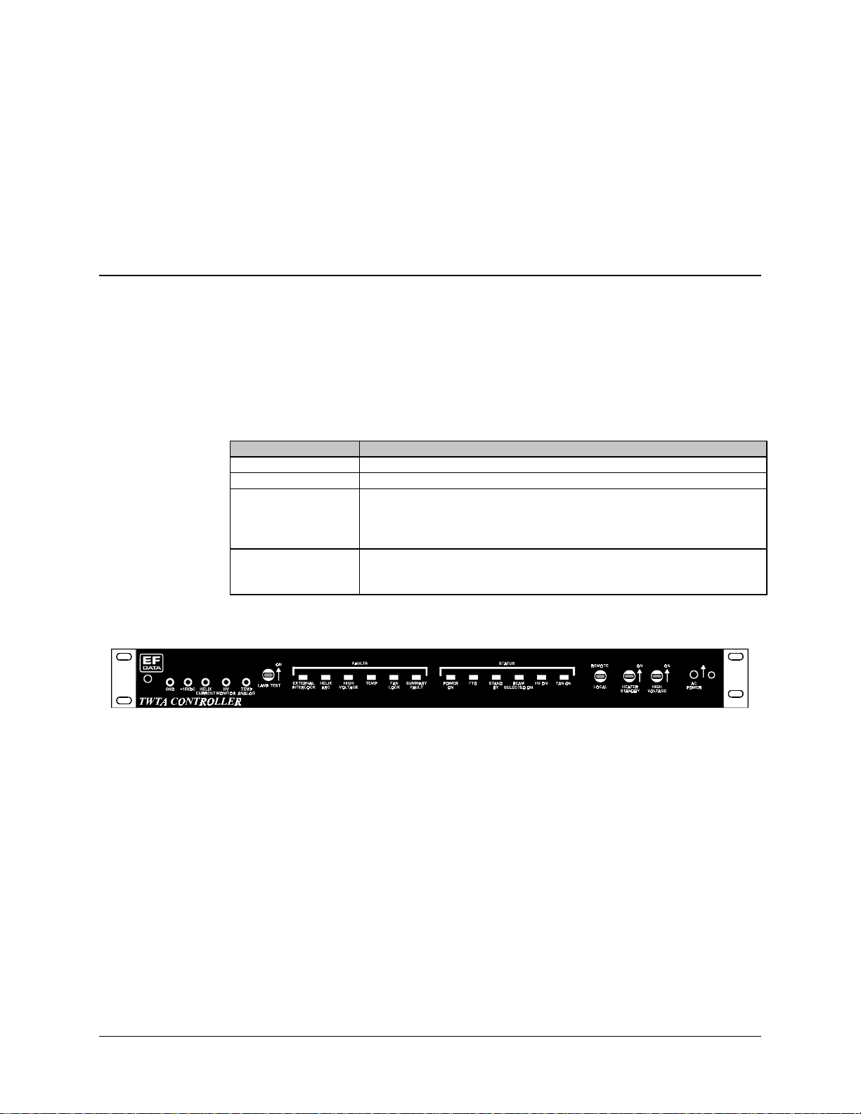
1.2.4.1 HPC-1200
The HPC-1200 (Figure 1-7) is specifically designed to monitor and control a TWTA in a
single thread configuration. Refer to Figure Chapter 1-4 for a description of the HPC-
1200.
Table Chapter 1-4. Description of the HPC-1200
Component Description
EFData Part No. RF/XCT-100
Connector 25-Pin D output connector for integ ra tion with other M&C eleme nts.
Local Control Can provide local control at the HPC site, or control f rom a remote site through
a remote interface to the HPC.
This is a manual selection at the HPC site.
Front Panel The front panel prov ide s c ontrol s witches and indicators, a r ea r pa ne l of
discrete interface connections for the TWTA, and a remote interface control
connector.
Figure Chapter 1-7. HPC-1200 Single Thread Controller
1–10 Rev. 1
Page 27
High-Power TWTA Satellite Terminals Introduction
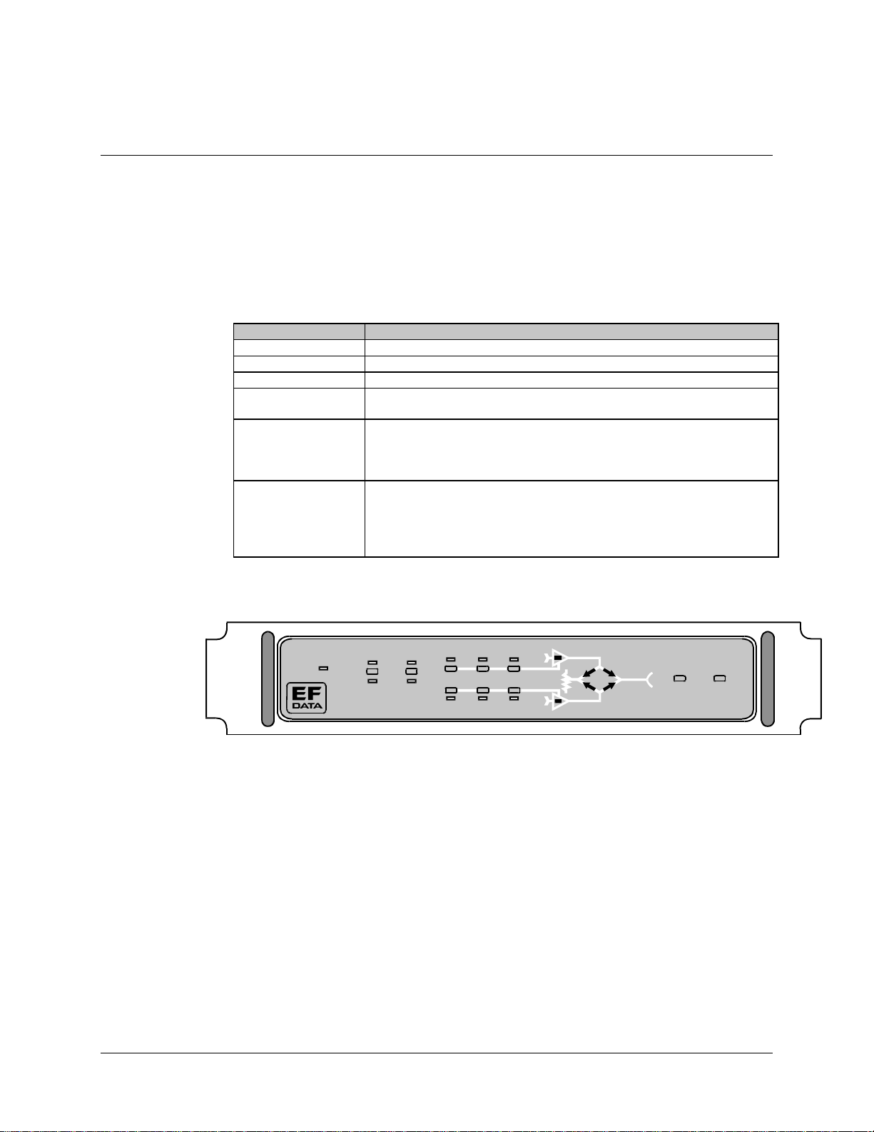
1.2.4.2 HPC-1110
The HPC-1110 (Figure 1-8) is specifically designed to monitor and control a TWTA
in a 1:1 redundant configuration. Refer to Table 1-5 for a description of the
HPC-1110. Refer to Appendix A for programming guidelines.
Table Chapter 1-5. Description of the HPC-1110
Feature Description
EFData Part No. RF/XTC-111D
Auto Mode For automatic operation when switched from offline to online system.
Power Supply TWTA is power from an A C input.
Control Interface The control interface from the TWTA to the HPC is parallel (discrete) signal
lines.
Local Control Provides local control at the H PC site , or c ontrol from a remote site throug h a
remote control interface.
This is a manual selection at the HPC site.
Panels The front panel prov ide s c ontrol s witches and indicators. A re a r pa ne l of
discrete interface connections for the TWT A, an interlock connector input, a nd
a remote interface control connector. Also, an input is provided for the
waveguide switch position indicators. A f a ult indica tor a nd f a ult r es e t is
provided for each channel.
Remote
Power
1:1 CO NTROLLER
Auto matic
Local Manual
TWTA
Power
Heater
Standby
HV O N
A
Fault R eset Lamp Test
B
Figure Chapter 1-8. HPC-1110 1:1 Redundant Controller
Rev. 1 1–11
Page 28

Introduction High-Power TWTA Satellite Terminals
1.2.5 Redundant Switch Unit (RSU)
The RSU-503L (Figure 1-9) is an all-weather unit that provides for primary and backup
operation as a communications terminal.
The RSU is designed for mounting on either the antenna or support pole.
The RSU controls the switching from primary to backup service in a 1:1 redundant
configuration.
For information on the RSU-503L, refer to the RSU-503 Redundancy Switch Unit
Installation and Operation Manual.
Figure 1-9. RSU-503L
1–12 Rev. 1
Page 29

High-Power TWTA Satellite Terminals Introduction
1.3 Equipment List
Refer to Table 1-6 through Table 1-10 for an equipment list for single thread and
redundant systems.
Notes:
1. These lists are subject to change without notice.
2. Indented part numbers are subsets of higher level part numbers, and are shown
for reference only.
Table 1-6. HPCST-5000/-7000 Single Thread Systems Equipment List (Typical)
Description EFData Part Number Notes
Single CST-5000 System:
RFT-500 (No TWTA)
RFT-700 (No TWTA)
Std Cable, AC
Std Cable, DC
Univ Mounting Kit
Single C-band LNA System
LNA Assy, EFD Std CST
Single HPCST-5000/7000 System
Single HPCST-5000 System
Single System Cable Harn ess
Waveguide ABS 1:2 Ku-b and
HPA-500/700 TWT Amplifier
C-Band HPA TWTA 140W
C-Band HPA TWTA 350W
Mounting Kit, HPA (C/KST)
.CST500....../.CST700.......
.RFT500/.......
.RFT700/.......
KT/3272-1
KT/3272-2
KT/3576
.CA.......
.HPCST500..../.HPCST700.....
PL/5129
CA/5124
KT/5115
.HPA500..../.HPA700.....
RF/XT-100C
RF/XT-400C
KT/5032
option
option
option
option
option
option
HPC-1200
RF/XTC-100
option
Rev. 1 1-13
Page 30

Introduction High-Power TWTA Satellite Terminals
Table 1-7. HPCST-5000 and -7000 Redundant Systems Equipment List (Typical)
Description EFData Part Number Notes
1:1 CST-5000/7000 System:
RFT-500 (No TWTA)
RFT-700 (No TWTA)
Univ Mounting Kit
RSU-503L
.REDCST500...../.REDCST700.........
.RFT500/A 00 1 2D 0
.RFT700/A 00 1 1A 0
KT/3577
.RSU503L (AS/3000-1)
option
option
1:1 LNA System:
Plate Assy, RCST LNA
LNA Assy
1:1 HPCST-5000/7000 Cable/Hardware Kit:
CBL/Hdw, R_CST, AC, 9m Ant
CBL/Hdw, R_CST, AC, Uplk, 4.6m Ant
1:1 HPCST-5000/7000:
1:1 High Power CSAT
Waveguide Assembly
Waveguide ABS 1:2 C-band
Mounting, 1:1 HPWR C/KSAT
HPA-500/700 TWT Amplifier
C-band HPA-500/140W
xtd_C-band HPA-700/140W
C-band HPA-500/350W
xtd_C-band HPA-700/350W
CBL/Hdw, RHPA, 115V, Uplink Only
Cable Harness, Uplnk, 4.6 Ant
Pwr Cable, 115 VAC
CBL/Hdw, RHPA, 230V
1:1 Cable Harness, 9m Ant
Pwr Cable, 230 VAC
CBL/Hdw, RHPA, 230V
1:1 Cable Harness, Sys
Pwr Cable, 230 VAC
.CSRED..........
AS/3220
.CA......
(no dot code)
KT/3107-7
KT/tbd
.HPCST5000RED......./.HPCST7000RED......
AS/5127
PL/5089
KT/5115
KT/5125
.HPA500..../HPA700......
RF/XT-100C
RF/XT-100CI
RF/XT-400C
RF/XT-400CI
KT/5249 -1
CA/5248
PL/5240-1
KT/5249 -2
CA/5122
PL/5240
KT/5249 -3
CA/5122-1
PL/5240
option
option
option
option
option
option
option
option
option
option
option
CBL/Hdw, RHPA, 230V, Uplnk Only
1:1 Cable Harness, 4.6m Ant
Pwr Cable, 230 VAC
HPC-1110 RF/XTC-111D option
KT/5249-4
CA/5248
PL/5240
option
1-14
Rev. 1
Page 31

High-Power TWTA Satellite Terminals Introduction
Table 1-8. HPKST-12000 Single Thread System Equipment List (Typical)
Description EFData Part Number Notes
Single Thread KST-12000 System:
RFT-1200 (No TWTA)
Std Cable/Hdw Ki t, AC
Std Cable/Hdw Kit, DC
Univ Mounting Kit
LNA System
LNA Assy, EFD Std KST
Single HPKST-12000 System
HPWR KST Assembly
Waveguide ABS 1:2 Ku-b and
Mounting Kit, TWTA (C/KST)
HPA-1200 TWT Amplifier
Ku-band HPA-1200/125W
Ku-band HPA-1200/300W
.KST12000.......
.RFT1200.......
KT/3954-1
KT/3954-2
KT/3576
.KA............
.HPKST1200....
PL/5130
KT/2820
KT/5032
.HPA1200......
RF/XT-100K
RF/XT-400K
option
option
option
option
option
option
CBL/Hdw, Single HPKST
Cable Harness, System
Pwr Cable, 115 VAC
CBL/Hdw, Single HPKST
Cable Harness, ? Ant
Pwr Cable, 230V
HPC-1200
KT/_ _ _ _ - tbd
CA/5124 - tbd
PL//5240-1
KT/_ _ _ _ - tbd
CA/5124 -tbd
PL//5240
RF/XTC-100
option
option
option
Rev. 1 1-15
Page 32

Introduction High-Power TWTA Satellite Terminals
Table 1-9. HPKST-12000 Redundant System Equipment List (Typical)
Description EFData Part Number Notes
1:1 KST-12000 System: .REDKST12000.......
RFT-1200 (No TWTA) RFT1200/A 00 1 2D 1 option
Univ Mounting Kit KT/3577
RSU-503L .RSU503L (PL/3000-1)
1:1 LNA System: .K1RED..........
Plate Assy, Std. LNA AS/4386 option
LNA Assy. KA....
Plate Assy, C03 LNA AS/3957 option
LNA Assy KA....
Plate Assy, C11 LNA AS/5223 option
LNA Assy. KA....
1:1 HPKST-12000 Cable/Hardware Kits (no dot code)
CBL/Hdw, R_C/KST, AC, 9mAnt KT/3950-5 option
CBL/Hdw, R_C/KST, AC, Uplk, 4.6m Ant KT/3950-6 option
CBL/Hdw, R_C/KST, AC, Uplk, 4.6m Ant KT/3950-8 option
1:1 High Power (HPKST-12000 System): .HPKST12000RED....
1:1 High Power KST PL/5033
Waveguide Assembly PL/5088
Waveguide ABS 1:2 Ku-band KT/2820
Mounting, 1:1 HPWR C/KSAT KT/5125
HPA-1200 TWT Amplifier .HPA1200.......
Ku-band HPA-1200/125W RF/XT-100K option
Ku-band HPA-1200/300W RF/XT-400K option
CBL/Hdw, RHPA, 115V, Uplink Only KT/5249 -1 option
1:1 Cbl Harness, Uplnk, 4.6 Ant CA/5248
Pwr Cable, 115 VAC PL/5240-1
CBL/Hdw, RHPA, 230V KT/5249 -2 option
1:1 Cable Harness, 9m Ant CA/5122
Pwr Cable, 230 VAC PL/5240-1
CBL/Hdw, RHPA, 230V KT/5249 -3 option
1:1 Cable Harness, Sys CA/5122-1
Pwr Cable, 230 VAC PL/5240
CBL/Hdw, RHPA, 230V, Uplnk Only KT/5249-4 option
1:1 Cable Harness, 4.6m Ant CA/5248
Pwr Cable, 230 VAC PL/5240
HPC-1110 RF/XTC-111D option
1-16
Rev. 1
Page 33

High-Power TWTA Satellite Terminals Introduction
1.4 Specifications
1.4.1 System Interface
Table 1-10 lists the types of interface required for each system component.
Table 1-10. System Interfaces for System Components
Description Type
RFT-500, -700:
TX IF Input (J1)
RX IF Output (J3)
RX RF Input (J4, C-band)
TX RF Output (J2, C-band)
M&C Control (J6)
RFT-1200:
TX IF Input (J1)
RX IF Output (J3)
RX RF Input (J4, Ku-band)
TX RF Output (J2, Ku-band)
M&C Control (J6)
HPA-500, -700:
RF TX Output (W/G Port)
RF RX Input (J3, C-band)
RF TX Sample (J4, C-ba nd)
M&C Control (J2)
HPA-1200:
RF TX Output (W/G Port)
RF RX Input (J3, Ku band)
RF TX Sample (J4, Ku-band)
M&C Control (J2)
Redundant TWTA Assembly
Customer Interface (P1) Circular type, PTO6E-20-41S
LNA Assy.:
RF RX Input (W/G)
RF RX Output (2x)
Block Converter Output
1:1 Switch Control
HPC-1110:
ODU #1 M&C (J1)
ODU #2 M&C (J2)
Remote M&C (J3)
W/G Switch #1
External Interlock
1:1 TWTA W / G Switch Control Circular, MS3116E-14-12P
TNC female , 50Ω, VSWR 1.25:1 max.
TNC female , 50Ω, VSWR 1.25:1 max.
N, female , VSW R 1.25:1 max.
N, female , VSW R 1.25:1 max.
Circular, PT06E-16-26S
TNC female, 50Ω, VSWR 1.25:1 max
TNC female, 50Ω, VSWR 1.25:1 max
N, female , VSW R 1.25:1 max
N, female , VSW R 1.25:1 max
Circular type, PT06E- 16-26S
CPR-137G, VSWR:
2.2:1 max. (for 140W ) , or 1.3:1 (for 350W)
N, female, VSWR: 1.3:1
N, female, VSWR: 1.3:1; typical 42 dB coupler
Circular, PT06E-18-32S
WR-75 G, VSWR:
2.2:1 max. (for 100W ) or 1.3:1 ( for 300W)
N, female, VSWR: 1.3:1
N, female, VSWR: 1.3:1; typical 42 dB coupler
Circular type, PT06E- 18-32S
CPR-229G, VSWR 1.25:1 ma x. (C-band)
WR-75 G, VSWR 1.25:1 max (Ku-band)
N, VSWR 1.25:1 max., female
N, VSWR 1.3:1 max., female
Circular, PT06E-14-19P
D-type, 37 pin, female
D-type, 37 pin, female
D-type, 9 pin, female
D-type, 15 pin, male
D-type, 15 pin, male
Rev. 1 1-17
Page 34

Introduction High-Power TWTA Satellite Terminals
Table 1-10. System Interfaces for System Components (Continued)
Description Type
RSU-503L:
M&C for RFT #A (J4)
IF RX Input (J2)
IF TX Output (J1)
M&C for RFT #B (J8)
IF RX Input (J6)
IF TX Output (J5)
Remote M&C (J16)
IF RX Output (J15)
IF TX Input (J14)
Waveguide Sw itch (J10)
Circular, PT06E-16-26S
TNC, female
TNC, female
Circular, PT06E-16-26S
TNC, female
TNC, female
Circular, PT06E-16-26S
TNC, female
TNC, female
Circular, PT06E-14-19S
1.3.2 Prime Power
Table 1-11 specifies the prime power specifications for each system component.
Table 1-11. Prime Power
Assembly Options Prime Power
RFT-500, -700 (J5) AC 90 to 230 VAC, 47 to 63 Hz, 1.0A
RFT-1200 (J5) AC 90 to 230 VAC, 47 to 63 Hz, 1.0A
HPA-500, -700 (J1):
140W
350W
HPA-1200 (J1):
100 W
300 W
HPC-1110 AC 90 to 230 VAC, 47 to 63 Hz
RSU-503L (J4, J8) DC +10.8 VDC from either RFT
LNA DC +10.8 ± 0.2 VDC as provided f r om RSU
AC
AC
AC
AC
Prime Power/Power C o n sumpti on
115 or 230 VAC,
100 to 230 VAC, 47 to 63 Hz, 1550 VA
Prime Power/Power C o n sumpti on
115 or 230 VAC,
100 to 230 VAC, 47 to 63 Hz, 1550 VA
20%, 47 to 63 Hz, 950 VA
±
20%, 47 to 63 Hz, 950 VA
±
1-18
Rev. 1
Page 35

High-Power TWTA Satellite Terminals Introduction
1.4.3 Performance
1.4.3.1 Receive
The receiver performance is defined for the LNA input to the 70 MHz output of the RFT
units.
Note: Intervening cable losses due to installation variables must be considered when
comparing the performance data listed in Table 1-12.
Table 1-12. HPCST-5000/-7000 Receive Characteristics
Receive Characteristics
Input Frequency Ra ng e , R FT-500 3.625 to 4.200 GHz, in 2.5 MHz steps
Input Frequency Ra ng e , R FT-700 4.50 to 4.80 GHz, in 2.5 MHz steps
Frequency Sens e No inversion
Input Level -127 to -80 dBm
RX Gain
Adj. (1 dB max. steps)
RX Freq. Stability
Life RX Freq. Drift
Gain Flatness
RX IF Output Bandwidth 70 ± 18 MHz at 1 dB
Noise Figure
Transmit Freq. Reject 60 dB
Receive Image Rejection -45 dBc
Linearity (Third Order Intercept) -30 dBc for 2 tones at -88 dBm (w ith LNA)
Group Delay (a ny 36 MHz)
Linear
Parabolic
Ripple
Synthesizer Lock Time < 1 second
Phase Noise(SSB) at:
10 Hz
100 Hz
1 kHz
10 kHz
100 kHz
Spurious (signal related) a t 0 dBm RX IF
output
Inband Overdrive No damage to 0 dBm
Third Order Interce pt +24 dBm minimum
RX IF Output at 1 dB Compres s ion +17 dBm minimum
95 dB min.
0 to 15 dB min. (remote ly controlled)
1 x 10⁻⁸ at 23°C
±
1 x 10⁻⁷ at 23°C
±
1.0 dB/36 MHz
±
+0.5 dB/4 MHz
65°K (other options available)
IESS-309, Figure 3, < 10 ns
0.28 ns/MHz
0.025 ns/MHz
< 5 ns P-P
(Maximum)
-30 dBc/Hz
-60 dBc/Hz
-70 dBc/Hz
-75 dBc/Hz
-80 dBc/Hz
-40 dBc
2
Rev. 1 1-19
Page 36

Introduction High-Power TWTA Satellite Terminals
Table 1-12. HPKST-12000 Receive Characteristics (Continued)
Receive Characteristics
Input Frequency Ra ng e 10.95 to 12.75 GHz
(2.5 MHz step size, 1.0 MHz option)
Frequency Sens e No inversion
Input Level -127 to -80 dBm
RX Gain
Adj (1 dB max steps)
RX Frequency Stability
Life RX Frequency Drift
Gain Flatness
RX IF Output Bandwidth 70 ± 18 MHz at 1 dB
Noise Figure 120°K (options to 90°K)
Transmit Freque nc y Reject 60 dB
Receive Image Rejection -45 dBc
Linearity
(Third Order Interc e pt) -35 dBc for 2 tones at - 86 dBm pin (with LNA)
Group Delay (a ny 36 MHz):
Linear
Parabolic
Ripple
Synthesizer Lock Time
Phase Noise (SSB) at:
10 Hz
100 Hz
1 kHz
10 kHz
100 kHz
Spurious (signal related):
at 0 dBm RX IF output -40 dBc
Inband Overdrive No damage to 0 dB m
Third Order Intercept
RX IF Output:
at 1 dB Compress ion
95 dB min
0 to 15 dB min (remote ly controlled)
1 x 10⁻⁸ at 23°C
±
1 x 10⁻⁷ at 23°C
±
1.0 dB/36 MHz
±
0.5 dB/4 MHz
±
IESS-309, Figure 3, < 10 ns
0.28 ns/MHz
0.025 ns/MHz
5 ns P-P
<
1 second
<
Maximum
-30 dBc/Hz
-60 dBc/Hz
-70 dBc/Hz
-75 dBc/Hz
-90 dBc/Hz
24 dBm min
+
17 dBm min
+
1-20
Rev. 1
Page 37

High-Power TWTA Satellite Terminals Introduction
1.4.3.2 Transmit
The transmit performance is the summation of the effects of the RFT and TWTA units.
Note: Intervening cable losses due to installation variables must be considered when
comparing the performance data listed in Table 1-13 through Table 1-16.
Table 1-13. HPCST-5000/-7000 Transmit Characteristics
Transmit Characteristics
Frequency Ra ng e :
RFT-500
RFT-700
System G a in:
140W System:
at 6 dB backoff, small signal
at saturated pwr, large signa l
350W System:
at 6 dB backoff, small signal
at saturated pwr, large signa l
TX IF Input Level Ra ng e -35 to -25 dBm typical
Output Power at saturation:
170W TWT
400W TWT
TX IF Input Bandwidth at -1 dB 70 ± 18 MHz
Gain: Stability (over temp.)
Flatness
Variation
Group Delay (a ny 36 MHz):
Linear
Parabolic
Ripple
TX Freq. Stability ± 1 x 10
TX Synthesizer L oc k - up time < 1 second
Spurious (not inter-mods):
at 6 dB backoff
with carrier off
5.845 to 6.425 GHz, in 2.5 MHz ste ps
6.725 to 7.025 GHz, in 2.5 MHz ste ps
73 dB min.
78 dB min.
77 dB min.
83 dB min.
140W
350W
+1.5 dB (matched RFT with TWTA)
±
1.5 dB/36 MHz
+2.0 dB max.
IESS-309, Figure 3, < 10ns
0.28 ns/MHz
0.15 ns/MHz
< 5 ns P-P
IESS-309, Paragraph 3.2.1
-40 dBc min. (
-50 dBc min. (> 2.048 MHz inform. rate)
-24 dBm/4 kHz ma x . (a nywhere in satellite band)
2
-8
2.048 MHz inform. rate )
≤
Intermod Spurious with two equal carriers
Harmonic (out of ba nd)
TX Phase Noise(SSB) at:
10 Hz
100 Hz
1 kHz
10 kHz
100 kHz
Rev. 1 1-21
-22 dBc at 6 dB back off
-60 dBc at 6 dB back off
(Maximum)
-30 dBc/Hz
-60 dBc/Hz
-70 dBc/Hz
-75 dBc/Hz
-80 dBc/Hz
Page 38

Introduction High-Power TWTA Satellite Terminals
Table 1-14. HPA-500, -700 Transmit Characteristics
Transmit Characteristics
TWT Rate d Pow e r 170W 400W
Rated Output Power at Flange:
140W
Gain (minimum):
Large signal (LSG)
Small signal (SSG)
42 dB min.
46 dB min.
Maximum SSG Variation:
Any 40 MHz ba nd
IF full Band
Slope
Stability (24 hr)
Stability, Temp
Inter-modulation:
(with two equal signals)
1.0 dB max.
2.5 dB max.
0.04 dB/MHz max.
0.25 dB max.
±
1.0 dB max.
±
-18 dBc max. w ith two equal carriers at 4 dB tota l output
backoff
Harmonic Output 60 dBc min.
AM to PM Conversion 2.5°/dB a t 6 dB be low rated power
Group Delay :
Linear (LDD)
Parabolic (PDD)
Ripple
(any 40 MHz)
0.01 ns/MHz
0.005 ns/MHz
0.5 ns p-p
≤
2
Noise Power:
Transmit band
Receive band
-80 dBW/4 kHz
-160 dBW/4 kHz
Residual AM Noise -50 dBc to 10 kHz
-20 (1.5 + logf) dBc to 500 k H z
-85 dBc above 500 kH z
Phase Noise 10 dB below IESS pha s e nois e profile
AC fundam e nta l - 50 dBc
Sum of all spurs - 47 dBc
350W
47 dB min.
52 dB min.
1.0 dB max.
2.5 dB max.
0.04 dB/MHz max.
0.25 dB max.
±
1.0 dB max.
±
-70 dBW/4 kHz
-150 dBW/4 kHz
1-22
Rev. 1
Page 39

High-Power TWTA Satellite Terminals Introduction
Table 1-15. HPKST-12000 Transmit Characteristics
Transmit Characteristics
Frequency Ra ng e , R FT-1200 14.0 to 14.5 GHz
(2.5 MHz step size, 1.0 MHz option)
Output Power at Saturation:
125W TWT
350W TWT
TX IF Input Level Ra nge -35 to -25 dBm
System G a in:
100W System:
at 6 dB backoff, small signal
at saturated pwr, large signa l
300W System:
at 6 dB backoff, small signal
at saturated pwr, large signa l
TX IF Input Bandwidth at -1 dB 70 ± 18 MHz
Gain Stability (over temp):
Flatness
Variation
Group Delay (a ny 36 MHz):
Linear
Parabolic
Ripple
TX Frequency Stability
TX Synthesizer L oc k - up Time
Spurious (not inter-mods):
at 6 dB backoff
with carrier off
Intermod Spurious:
with two equal carrie rs
Harmonic (out of ba nd)
TX Phase Noise (SSB) at:
10 Hz
100 Hz
1 kHz
10 kHz
100 kHz
100W
300W
72 dB min
77 dB min
78 dB min
82 dB min
1.5 dB (matched RFT with TWTA)
±
1.5 dB/36 MHz
±
2.0 dB max
±
IESS-309, Figure 3, < 10 ns
0.28 ns/MHz
0.15 ns/MHz
5 ns p-p
≤
-8
1 x 10
±
< 1 second
IESS-309, Paragraph 3.2.1
-40 dBc min (
2.048 MHz inform rate )
≤
-50 dBc min (> 2.048 MHz inform rate)
-24 dBm/0.4 kHz ma x (a nywhere in satellite band)
-22 dBc at 6 dB back off
-60 dBc at 6 dB back off
Maximum
-30 dBc/Hz
-60 dBc/Hz
-70 dBc/Hz
-75 dBc/Hz
-80 dBc/Hz
Rev. 1 1-23
Page 40

Introduction High-Power TWTA Satellite Terminals
Table 1-16. HPA-1200 Transmit Characteristics
Transmit Characteristics
TWT Rated O utput Pow e r 125W 350W
Rated Output Power at Flange
100W
Gain (minimum):
small signal (SSG)
large signal (LSG)
42 dB min.
46 dB min.
Maximum SSG Variation
Any 80 MHz ba nd
Full Band
Slope
Stability (24 hr.)
Stability, Temp
Intermodulation:
(with two equal signals)
1.0 dB max.
2.5 dB max.
0.04 dB/MHz max.
0.25 dB max.
±
1.0 dB max.
±
-18 dBc max. w ith two equal carriers at 4 dB tota l output
backoff
Harmonic Output -60 dBc max.
AM to PM Conversion 2.5°/dB at 6 dB below rated power
Group Delay :
Linear
Parabolic
Ripple
(any 80 MHz)
0.02 ns/MHz
0.005 ns/MHz
1 ns p-p
≤
2
Noise Power:
Transmit band
Receive band
-80 dBW/4 kHz
-160 dBW/4 kHz
Residual AM Noise -50 dBc to 10 kHz
-20 (1.5 + logf) dBc to 500 k H z
-85 dBc above 500 kH z
Phase Noise 10 dB below IESS phase nois e pr ofile
AC fundam e nta l - 50 dBc
Sum of all spurs - 47 dBc
300W
47 dB min.
52 dB min.
1.0 dB max.
2.5 dB max.
0.04 dB/MHz max.
0.25 dB max.
±
1.0 dB max.
±
-70 dBW/4 kHz
-150 dBW/4 kHz
1-24 Rev. 1
Page 41

High-Power TWTA Satellite Terminals Introduction
1.4.4 Environment
Note:
RFT and TWTA are considered Outdoor Units (ODUs) and will appear as such
throughout this manual.
The maximum environmental conditions applicable to the ODUs are listed in Table 1-17.
Table 1-17. ODU Environmental Specifications
Environment Conditions
Temperat ure -40° to +50°C operating
-50° to +70°C surv iv a l, non- ope ra ting
Vibration 1.5g, 5 to 200 H z a nd normal transportation levels
Shock 6g max.
Humidity 0% to 100% relative at -40° to +50° C
%
95
at 65°C for 72 hrs .
Precipitation MIL-STD-810/Method 506.2
Salt Fog MIL-STD-810/Method 509.2
Sand and Dust MIL-STD-810/Method 510.1
Altitude:
Operational
Survival
Solar Radiation 360 BTU/hr/ft2 at 50°C
Safety TBD
Emissions TBD
ES Discharge 10 kV operation, 15 kV surviva l
0 to 10,000 ft.
0 to 40,000 ft.
Note: HPCs are considered indoor units (IDUs) and appear as such throughout this
manual.
The maximum environmental conditions applicable to the IDUs are listed in Table 1-18.
Table 1-18. IDU Environmental Specifications
Environment Conditions
Temperat ure 0° to +50°C opera ting
-10° to +70°C surv iv a l
Vibration and Shock Normal transportation lev e ls
Humidity 0% to 75% relative +50°C operating
%
95
at 50°C for 72 hr. non-ope r a ting
Altitude 0 to 10,000 ft.
Safety TBD
Emissions FCC Part 15, J, Class A
Rev. 1 1-25
Page 42

Introduction High-Power TWTA Satellite Terminals
1.4.5 Monitor and Control
The HPCST-5000/-7000, and HPKST-12000 systems have a single interface connector
(41-pin connector) located on the TWTA redundant assembly. This interface provides
the customer with control of the ODU redundant assemblies through the integrated
system wire harness.
Refer to Table 1-19 for customer control mechanism options that can be connected to the
P1 connector.
Table 1-19. Monitor and Control
System Type Interface M&C Optio ns
CST-5000, -7000, or
KST-12000 Redundant A s s y.
HPA-500, -700, or -1200
Redundant Assy.
EIA-232/
EIA-485
serial bus
Discrete I/O Hard-wired at P1, f rom an HPC-1110 controller,
Keypad or Sy ste m Controller (customer prov ide d
PC) through a customer interface connector (P1)
located on the TWTA redundant assembly.
or from a Sy s te m Controller (customer -pr ov ide d)
connected to P1.
1-26 Rev. 1
Page 43

High-Power TWTA Satellite Terminals Introduction
1.4.6 Physical Size and Weight
The physical size and weight of the system components are listed in Table 1-20.
Table 1-20. Physical Size and Weight Characteristics
Component Maximum Size and Weight, Inches Maximum Size and Weight, Metrics
RFT-500, -700,
-1200:
Single Thread
Redundant
HPA-500, -700:
Single Thread:
140W
350W
Redundant:
140W
350W
HPA-1200:
Single Thread:
100W
300W
Redundant:
100W
300W
HPC-1200 19” L x 18” W x 3.5” H, T B D lb.
HPC-1110 19” L x 6.6” W x 1.6” H, TBD lb.
RSU-503L 8” L x 11” W x 8” H, 7.5 lb. 20.32 x 27.94 x 20.32 cm; 3.40 kg
LNA Assy. (Dual):
C-Band
Ku-Band
23” L x 9.3” W x 10.3” H, 40 lb. max.
Not Specified
16” L x 8.6” W x 9” H, 45 lb.
21” L x 10.3” W x 11” H, 55 lb.
(includes W/G c om pone nts and sw itc h)
32” L x 32” W x 12” H, 95 lb.
32” L x 36” W x 15” H , 160 lb.
16” L x 8.6” W x 9” H, 45 lb.
21” L x 10.3” W x 9” H, 55 lb.
32” L x 32” W x 12” H, 95 lb.
32” L x 32” W x 15” H , 150 lb.
(w/brackets)
(w/brackets)
26” L x 21” W x 14” H, 20 lb.
12” L x 7.1” W x tbd H, TBD lb.
58.42 x 23.6 x 26.16 cm; 18.1 kg
40.63 x 21.84 x 22.86 cm; 20.41 kg
53.34 x 26.16 x 27.94 cm; 24.95 kg
81.28 x 81.28 x 30.48 cm; 43.1 kg
81.28 x 91.44 x 38.1 cm; 72.57 kg
40.63 x 21.84 x 22.86 cm; 20.41 kg
53.34 x 26.16 x 22.86 cm; 24.95 kg
81.28 x 81.28 x 30.48 cm; 43.1 kg
81.28 x 91.44 x 38.1 cm; 68.04 kg
48.26 x 45.72 x 8.89 cm
48.26 x 16.76 x 4.064 cm
66.4 x 53.34 x 35.56 cm; 9.072 kg
30.48 x 18.03 cm
Rev. 1 1-27
Page 44

Introduction High-Power TWTA Satellite Terminals
Refer to Figure 1-11, 1-12, and 1-13 for unit envelope. All dimensions are in inches,
centimeters are listed in parenthesis.
10.60
(26.9 2 )
10.25
(26.0 5 )
20.50
(52.0 7 )
MAX
7.53
(19.1 3 )
Figure 1-11. TWTA Outline Drawing (Typical)
1-28 Rev. 1
Page 45

High-Power TWTA Satellite Terminals Introduction
6.54 in.
(
)
16.61 cm
19.00 in.
(
)
48.26 cm
GND +15VDC HELIX
TWTA CONTROLLER
CURRENTHVMONITOR
FAULT S STATUS
HIGH
TEMP BEAM
HELIX
VOLTAGE
ARC
LOCK
FAULT
POWER
STAND
FTDFAN
ON
BY
SELECTED ON
TEMP
ANALOG
LAMPTEST
ON
EXTERNAL
INTE RL OCK
Figure 1-12. HPC-1200 Outline Drawing
ON
HEATER
STANDBY
HIGH
VOLTAGE
ON
AC
POWER
1.61 in.
(
4.09 cm
)
REMOTE
HV ONSUMMARY
FAN ON
LOCAL
Rev. 1 1-29
Page 46
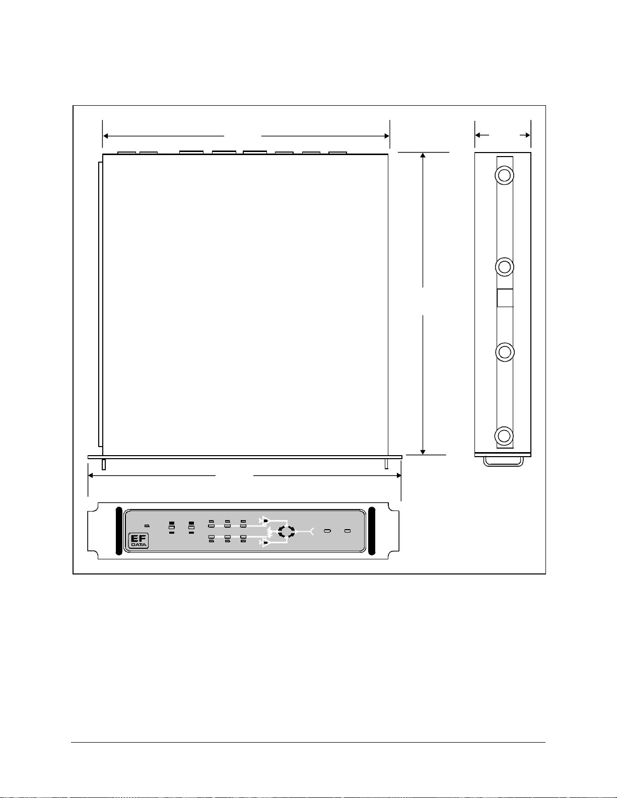
Introduction High-Power TWTA Satellite Terminals
17.0 in.
(43 .18 )
3.35 in.
(8.50)
18.0 in.
(45 .72 )
1
9.0 in
Remote
Power
1:1 CONTROLLER
(48 .26 )
Automatic
TWTA
Manual
Power
Loc al
Heater
Standby
HV ON
.
A
B
FaultReset Lamp Test
Figure 1-13. HPC-1110 Outline Drawing
1-30 Rev. 1
Page 47

Chapter 2.
SINGLE THREAD SYSTEM
INSTALLATION
22
This chapter provides installation instructions for the HPCST-5000/-7000, and KST12000 high-power satellite terminals in a single thread system configuration. For
installation instructions for related system components (RFT and LNA), refer to the
appropriate manual:
• CST-5000 C-Band Satellite Terminal Installation and Operation Manual
• CST-7000 C-Band Satellite Terminal (Insat) Installation and Operation Manual
• KST-12000 Ku-Band Satellite Terminal Installation and Operation Manual
High Voltage Hazards:
The TWTA utilizes high voltage that can be lethal if contacted. The
WARNING
TWTA should not be operated without its cover unless the user is
thoroughly familiar with its operation and experienced with high
voltage.
RF Radiation Hazards:
Prior to operation of the TWTA, ensure that all microwave connections
are securely fastened. Check that there is no microwave leakage from
them. Never operate the TWTA with an open waveguide. This amplifier
is capable of generating high power microwave radiation, which can
cause bodily harm.
Safety Summary:
Equipment of this nature has inherent hazards. Operator or service
technicians should have training on the TWTAs. When the TWTA’s
cover is removed, the high voltage power supply for the TWT has
multiple exposed high voltage points. Use extreme care when operating
the amplifier with its cover removed.
Rev.1 2–1
Page 48

Single Thread System Installation High-Power TWTA Satellite Terminals
2.1 Unpacking
The TWTA is packaged in preformed, reusable foam inside a cardboard carton.
Before unpacking the carton components, ensure that there is plenty of room around the
carton for workspace. A large table is recommended.
To remove the parts:
1. Cut the tape at the top of the carton where it is indicated OPEN THIS END.
2. Lift out the cardboard/foam spacer covering the unit.
3. Remove each part from the carton. Refer to Section 2.2.1 for a parts breakdown.
Because the TWTA is heavy, assistance may be necessary to remove
the unit from the box.
CAUTION
Note:
Save the packing material for reshipment.
2–2 Rev.1
Page 49

High-Power TWTA Satellite Terminals Single Thread System Installation
2.2 Inspecting the Equipment
1. Carefully check the equipment for damage incurred during shipment.
2. Carefully check the equipment against the packing list shipped with the
equipment to ensure that the shipment is complete. Refer to the following
paragraphs.
2.2.1 Included Parts
A typical single thread TWTA configuration contains the following components.
Notes:
1. Parts are not drawn to scale.
2. Because each system can be custom ordered, it is beyond the scope of this
manual to provide the unlimited configuration possibilities.
Qty. Description Qty. Description
1 TWT amplif ie r. 1 High-power TWTA Sa tellite T e rminals
Installation and Operation Manua l.
1 Envelope containing the te st da ta.
Notes:
1. C-Band TWTAs (HPA-500/-700) utilize waveguide kit KT/5115.
2. The Ku-Band TWTA (HPA-1200) utilizes waveguide kit KT/2820.
Rev.1 2–3
Page 50

Single Thread System Installation High-Power TWTA Satellite Terminals
1 C-band wav e gu id e c o n nector kit (EFD a t a Pa r t # KT 5115), which includes:
Qty. Description Qty. Description
1 Gasket —full.
1 Gasket — half- thic k ne ss .
EFData Part # FP/5195.
8 10-32 x 1” bolt.
EFData Part # 03P1097.
8 1/4” split lockwasher.
EFData Part # HW/10-SPLIT.
1 Ku-band wav eguide connec tor kit (EFData Part # KT/2820), which includ e s :
Qty. Description Qty. Description
2 O-Ring, -024, BUNA, black.
EFData Part # 32P1037.
8 6-32 x 7/8” socket h ead cap screw.
EFData Part # HW/GKT-CPR137G.
16 #10 flat was he r.
EFData Part # HW/10-FLT.
8 10-32 hex nut.
EFData Part # HW/10-32HEXNUT.
2 O-Ring, black neoprene.
EFData Part # 32P1039.
16 #6 flat was he r.
EFData Part # HW/6-32X7/8SHCS.
8 #6 split lockwasher.
EFData Part # HW/6-SPLIT.
2–4 Rev.1
EFData Part # HW/6-FLT.
8 6-32 hex nut.
EFData Part # HW/6-32HEXNUT.
Page 51

High-Power TWTA Satellite Terminals Single Thread System Installation
1 Cable kit (EFData Part # KT/5499), which includes:
Qty. Description Qty. Description
1 Cable assembly.
1 Cable assembly.
EFData Part # PL/2754.
1 Plug, dead front, 250V, 15 amp, 3-wire.
EFData Part # PP/AC-5666VY.
1 Conn., 26 Pin, Circular, Female, Wall Mnt.
w/seal.
EFData Part # CN/PT00E16-26S.
EFData Part # PL/5389.
1 Cable-Male to Male Heliax 12 ft.
EFData Part # CA/3722-1.
Rev.1 2–5
Page 52
Single Thread System Installation High-Power TWTA Satellite Terminals
1 Hardware kit (EFData Part # KT/5032), whic h in c ludes:
Qty. Description Qty. Description
4 Unistrut — 14” long.
4 5/16-18 x 1” bolt.
EFData Part # FP/3595.
Used for round and square pole m ount only.
8 Pipe block.
EFData Part # HW/BLK-PIPE2-8.
Used for round pole mount only.
4 Threaded rod, 5/16-18 x 14” .
EFData Part # HW/RD5/16-18X14.
Used for round and square pole m ount only.
8 Flat fitting plate, 5/16”.
EFData Part # HW/FIT-PLT-5/16.
16 5/16-18 spring nut.
EFData Part # HW/5/16-18SPNUT.
2 Unistrut — 8” long.
EFData Part # HW/5/16-18X1BLT.
24 5/16” split lockwasher.
EFData Part # HW/5/16-SPLIT.
24 5/16” flat was he r .
EFData Part # HW/5/16-FLT.
16 5/16-18 hex nut.
EFData Part # HW/5/16-18HEXNT.
2 Spar support bracket.
EFData Part # FP/3175.
Used for spar mount only.
8 5/16-18 x 1.25” bolt.
EFData Part # FP/3481-1.
Attaches directly to TWTA.
2–6 Rev.1
EFData Part # HW/5/16-18X1.25.
Page 53

High-Power TWTA Satellite Terminals Single Thread System Installation
2.3 TWTA Installation
At the customer’s discretion, the TWTA can be installed anywhere on or near the
antenna. The supplied hardware allows the installer a wide range of installation
alternatives, including:
• Vertical pole (e.g., mast) (either square or round). This is the most typical
installation.
• Within the hub of a large antenna.
EFData recommends that the TWTAs be mounted vertically.
Note:
A clearance of 2” (5.08 cm) is required for the air inlets and exhaust ports. If the
TWTA is mounted in an enclosed chamber, duct the exhaust air to the outside of the
chamber. Do not re-circulate the exhaust air back into the TWTA. Use an exhaust duct
that is slightly larger than the exhaust port of the TWTA and one that has smooth bends
and transitions.
Rev.1 2–7
Page 54

Single Thread System Installation High-Power TWTA Satellite Terminals
2.3.1 Tools Required
Qty. Description
1
3/8” drive ratchet.
1
3” x 3/8” drive ex tens ion.
1
7/16” x 3/8” drive sock e t. (Metric equivalent: 12mm, 6 pt.)
1
1/2” x 3/8” drive sock e t. ( Metric equivalent: 13mm, 6 pt.)
1 1/2” combination wrench. (Metric equivalent: 13mm combination wrench
with a 6 pt. box end.)
1
7/64” hex key ( Allen wrench). (No metric equivalent.)
1 5/16” combination wrench. (Metric equivalent: 8mm combination wrench
with a 6 pt. box end.)
2–8 Rev.1
Page 55

High-Power TWTA Satellite Terminals Single Thread System Installation
2.3.2 Vertical Pole Installation
2.3.2.1 Round Pole
Note:
The following process is for a typical installation. Custom systems may be
ordered, and are not included in this manual.
To install the TWTA to a round vertical pole:
1. Set the unit on its side, with the mounting holes facing up.
2. Install the two 14” unistruts as follows:
a. Position a 14” unistrut (with the open side facing up) over one set of the
mounting holes on the TWTA.
b. Using four 5/16-18 bolts, 5/16” split lockwashers, and 5/16” flat washers,
and 5/16-18 nuts, attach the 14” unistrut to the TWTA.
Tighten the bolts firmly.
c. Repeat Steps 2.a. and 2.b. for the second 14” unistrut.
3. Install the pipe blocks as follows:
a. Install two spring nuts in each of four 14” unistruts (the two just mounted on
the TWTA, and two additional).
Be sure to position the spring nuts in the unistruts wide enough apart so that
when the pipe blocks are installed, they will clear the pole when the unit is
lifted into place for installation.
b. Install each spring nut as follows:
(1) Place the spring nut in the unistrut channel, spring side down, with its
wide side parallel with the unistrut channel.
(2) Press down on the spring nut to compress the spring, and rotate the nut
90° (i.e., perpendicular to the unistrut).
Rev.1 2–9
Page 56

Single Thread System Installation High-Power TWTA Satellite Terminals
(3) Release pressure
on the spring nut.
(4) Repeat Steps
3.b.(1) through
3.b.(3) for each
spring nut.
c. Using four 5/16-18
bolts, 5/16” split
lockwashers, and 5/16”
flat washers, loosely
secure the pipe blocks
to the spring nuts.
Ensure the pipe blocks
are installed with the
long angle facing
inward, toward the
pipe, as illustrated.
Note:
DO NOT
tighten the pipe block
bolts until after
mounting the TWTA
on the vertical pole.
(See Step 5.e.)
2–10 Rev.1
Page 57

High-Power TWTA Satellite Terminals Single Thread System Installation
4. Install the threaded rods as follows:
a. Install two spring nuts in both 14”
unistruts mounted on the TWTA.
Note:
Ensure the spring nuts are
positioned over the outer holes in the
14” unistruts, as illustrated.
b. To install each spring nut:
(1) Place the spring nut in the
unistrut channel, spring side
down, with its wide side parallel
with the unistrut channel.
(2) Press down on the spring
nut to compress the spring, and
rotate the nut 90° (i.e.,
perpendicular to the unistrut).
(3) Release pressure on the spring nut.
(4) Repeat Steps 4.b.(1) through 4.b.(3) for each spring nut.
c. Thread a 5/16-18 nut approximately 1-1/2” onto each threaded rod. (This
will ensure that the threaded rods will extend beyond the spring nuts when
installed.)
d. Place a 5/16” split
lockwasher, 5/16” flat
washer, and flat fitting
plate over each
threaded rod.
Rev.1 2–11
Page 58

Single Thread System Installation High-Power TWTA Satellite Terminals
e. One threaded rod at a time, hold the
washers and plate in place on the rod,
and screw the rod into a spring nut, as
illustrated.
Notes:
1. Be sure to position the flanges
of the flat fitting plates in the
grooves of the unistruts.
2. Before tightening the nuts on
the threaded rods, ensure that
the end of each rod is screwed
in until it is flush with the
backside of the unistruts. This
ensures the rods are threaded
completely through the spring
nuts.
Tighten each nut firmly.
f. Thread a 5/16-18 nut about 2” onto the
end of each threaded rod.
g. Slip a 5/16” split lockwasher, 5/16” flat
washer, and flat fitting plate (in that
order) onto each threaded rod.
5. Mount the TWTA as follows:
a. Lift the TWTA into position on the
vertical pole.
b. Slip a 14” unistrut over each of pair of
threaded rods (upper and lower).
Note:
Install the 14” unistruts with the open face toward the pole, as
illustrated below.
2–12 Rev.1
Page 59

High-Power TWTA Satellite Terminals Single Thread System Installation
c. Install a 5/16” flat
washer, 5/16” split
lockwasher, and 5/1618 nut on each
threaded rod.
d. Position the TWTA as
desired, and tighten
the 5/16-18 nuts
installed in Step 5.c.
e. Slide the pipe blocks
inward until they
contact the vertical
pole, then firmly
tighten the 5/16-18
bolts.
2.3.2.2 Square Pole
For square vertical pole installation, follow the steps in Section 2.3.2.1, with the
following exceptions:
• Do not perform Step 3.
• Do not perform Step 5.e.
Rev.1 2–13
Page 60
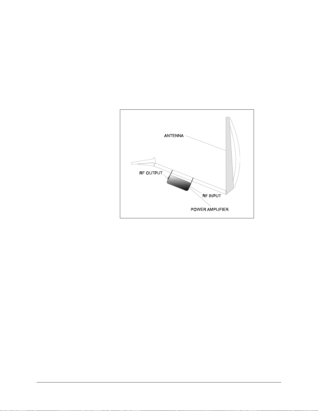
Single Thread System Installation High-Power TWTA Satellite Terminals
2.3.3 Spar Installation
Note:
The following process is for a typical installation. Custom systems may be
ordered, and are beyond the scope of this manual.
Figure Chapter 2-1 shows a typical spar-mounted TWTA.
Figure Chapter 2-1. Typical TWTA Spar Installation
To install the TWTA to a spar:
1. Set the unit on its side, with the mounting holes facing up.
2. Install the 8” unistruts as follows:
a. Position an 8” unistrut (with the open side facing up) over one set of the
mounting holes on the TWTA.
b. Using four 5/16-18 bolts, 5/16” split lockwashers, 5/16” flat washers, and
5/16-18 hex nuts, attach the 8” unistrut to the TWTA.
Tighten the bolts firmly.
c. Repeat Steps 2.a. and 2.b. for the second 8” unistrut.
2–14 Rev.1
Page 61

High-Power TWTA Satellite Terminals Single Thread System Installation
3. Mount the TWTA as follows:
a. Position a spring nut between the
inner and outer bolts on both sides
of each 8” unistrut, as illustrated.
b. Install each spring nut as follows:
(1) Place the spring nut in the
unistrut channel, spring side
down, with its wide side
parallel with the unistrut
channel.
(2) Press down on the spring nut
to compress the spring, and
rotate the nut 90° (i.e.,
perpendicular to the unistrut).
(3) Release pressure on the
spring nut.
(4) Repeat Steps 3.b.(1) through
3.b.(3) for each spring nut.
c. Lift the TWTA into position.
d. Using four 5/16-18 bolts, 5/16”
split lockwashers, and 5/16” flat
washers, bolt the two spar support
brackets in place.
Tighten the bolts firmly.
Rev.1 2–15
Page 62

Single Thread System Installation High-Power TWTA Satellite Terminals
2.3.4 External Connections
Connections between the TWTA and other equipment are made through five connectors.
These connectors are listed in Table Chapter 2-1, and their locations are shown in Figure
Chapter 2-2 and Figure Chapter 2-3.
The use of each connector is described in the following paragraphs.
Table Chapter 2-1. External Connections
Name Ref.
Design.
MONITOR AND
CONTROL
POWER J2 T3109-013 Prime power:
RF INPUT J3 N, female
RF SAMPLE J4 N, female Calibrated reference
RF OUT J5 WR-75G TX RF output:
J1 PT06E-18-32S (SR) Remote interfa c e
Connector
Type
115 VAC; 230 VAC, 47 to 63 H z
TX RF input, 50Ω input impedance
C-band (5845 to 6425 MHz)
Extended C-band (6725 to 7025 MHz )
Ku-band (14.0 to 14.5 GHz)
Function
Figure Chapter 2-2. 100W and 140W TWTA External Connections
2–16 Rev.1
Page 63

High-Power TWTA Satellite Terminals Single Thread System Installation
RF SAMPLE
(TY P E N)
POWER
MONITOR
AND CONTROL
RF INPUT
(TY P E N)
AIR EXHAUST AIR INLET
RF OUT
MOUNTING HOLESMOUNTING HOLES
Figure Chapter 2-3. 300W and 350W TWTA External Connections
Rev.1 2–17
Page 64

Single Thread System Installation High-Power TWTA Satellite Terminals
2.3.4.1 TWTA Monitor & Control (J1)
The TWTA is controlled using a discrete signal type interface. Table Chapter 2-2 lists
the pinouts for the 32-pin M&C connector.
Table Chapter 2-2. TWTA Monitor & Control Pinouts
Type Pins Functions
Control Commands
(All active low)
Status Indicators, digital outputs
(unless specified, all active low)
Status Indicators, ana log outputs b
Output Voltages
(power on indicator)
Ext. Voltage Input Y +5/15 VDC external s upply input
AC Power ON
a
High Voltage Enable
F
Heater Standby
J
Fault Reset
X
Control Common (T W T GND)
Z
Helix/Arc Fault Latche d
A
Helix/Arc/Fault
C
Heater Timer Complete
G
TWT Temperature Fault
H
High Voltage ON
K
Fan ON
M
High Voltage Fault
R
EXT Fault (Active = High)
S
Summary Fa ult
T
Fan Lock
U
Status Return (Floating Comm on)
W
Reserved
Helix Current
D
High Voltage Monitor
L
VDC/Analog Return (TWT GND)
N
TWT Temperature
P
E
+15 VDC (100 mA max.)
V
+24 VDC (100 mA max.)
B
Chassis Gr ound
Notes:
1. AC Power ON (Pin A) — Connect to ground (Pin Z) to apply power to unit.
2. High Voltage Enable (Pin F) — Connect to ground (Pin Z) to turn high
voltage ON.
3. Heater Standby (Pin J) — Connect to ground (Pin Z). The HV Enable
command overrides this command when enabled. If the HV Enable is
removed, TWT will return to a reduced TWT heater voltage.
An external control and monitor device may be connected to the TWTAs for operation of
the power amplifier. The optional EFData HPC-1200 controller can be used for this
purpose.
2–18 Rev.1
Page 65

High-Power TWTA Satellite Terminals Single Thread System Installation
There are five classes of interfaces (Figure Chapter 2-4):
Controls
•
Digital Status Circuits
•
• External Voltage Circuit
Analog Status Circuits
•
Output Voltage Circuits
•
Each class will be described in more detail in the following paragraphs.
Figure Chapter 2-4. Interface Connector Pinouts
Rev.1 2–19
Page 66

Single Thread System Installation High-Power TWTA Satellite Terminals
2.3.4.1.1 Control Interfaces
There are five control inputs as follows:
AC Power ON (Pin a).
•
Connect Pin a to ground (Pin Z) to enable operation of the amplifier and turn the
TWT heater on.
The AC control circuit does not affect the connection of the power
amplifier to prime power. Disconnect Prime Power when the power
CAUTION
High Voltage Enable (Pin F).
•
Connect Pin F to ground (Pin W) to turn high voltage on.
Heater Standby (Pin J).
•
Connect Pin J to ground (Pin W) to reduce the voltage applied to the TWT
heater. This feature is provided to extend the life of the TWT when the amplifier
is the back-up unit in a redundant configuration. The High Voltage ON overrides
the Heater Standby command and returns the TWT heater voltage to normal
operating value.
amplifier is serviced.
Fault Reset (Pin X).
•
Momentarily connect Pin X to ground (Pin W) to reset the high voltage fault and
helix current fault.
Note:
Turning the High Voltage OFF will also clear these faults.
AC Command Return (Pin Z).
•
Common return.
The external control inputs require +15 VDC pull-up. This is possible from the internal
+15 VDC of the amplifier or from an external DC supply. Both configurations are
described in the following paragraphs.
Using the Internal +15 VDC for Control, connect pin E to pin Y.
•
• Using an External DC Supply for Control, connect pin Y to external +15V
source and source return to pin W.
Note:
The EFData system harness is pre-wired to use the +15V output of the TWTA as
the input to the control pull-ups.
2–20 Rev.1
Page 67

High-Power TWTA Satellite Terminals Single Thread System Installation
2.3.4.1.2 Digital Status Circuits
The digital status interface circuits are isolated outputs that require an internal +15 VDC
supply or an external supply to bias the digital status indicator circuits. This is
accomplished in the same manner as the control inputs by either connecting pin Y to pin
E, or applying an external supply to pin Y.
The term “Active = low” is used in the following paragraphs to indicate when a
condition is true and the status indicator is active (e.g., the photo-diode is conducting).
Except for Control/Status Return, all circuits have a maximum open voltage of 20V, and
maximum switched current is 3 mA. Switches are isolated photo-couplers.
Helix/Arc Fault Latched (Pin A). (Active = low.)
•
When active, indicates there is a helix/arc fault within the amplifier when
Pin A (+) is connected by open collector to ground (Pin W). After three
successive helix/arc faults, the automatic cycle is terminated and this line is
active (low).
Helix/Arc Fault (Pin C). (Active = low.)
•
When active, indicates there is a helix/arc fault within the amplifier when
Pin C (+) is connected by open collector to ground (Pin W).
Note:
The amplifier will try to reset itself in the event of a helix/arc fault. This
line will “flash” during each reset cycle.
Heater Timer Complete (Pin G). (Active = low.)
•
When active, indicates the heater delay is in progress when Pin G (+) is
connected to by open collector to ground (Pin W).
TWT Temperature Fault (Pin H). (Active = low.)
•
When active, indicates there is a TWT Temperature fault within the amplifier
when Pin H (+) is connected by open collector to ground (Pin W). This is not a
latched fault. The amplifier automatically powers on once the TWT has cooled
to an acceptable temperature.
A TWT Temperature fault may occur from a number of causes:
! Air intake filter clogged
! Cooling fins clogged
! Fan failure
! Fan power supply failure
• High Voltage ON (Pin K). (Active = low.)
When active, indicates that the amplifier is on when Pin K (+) is connected by
open collector to ground (Pin W).
Rev.1 2–21
Page 68

Single Thread System Installation High-Power TWTA Satellite Terminals
• Fan ON (Pin M). (Active = low.)
When active, indicates that the amplifier’s main cooling fan is on when
Pin M (+) is connected by open collector to ground (Pin W). The main cooling
fan is controlled by the temperature of the TWT. The fan will cycle on and off in
cooler ambient conditions. The fan is typically operated below the
manufacturer’s nominal design voltage.
• High Voltage Fault (Pin R). (Active = low.)
When active, indicates there is a high voltage fault within the amplifier when
Pin R (+) is connected by open collector to ground (Pin W). A high voltage fault
is typically an indication of a serious power supply failure.
Summary Fault (Pin T). (Active = low.)
•
When active, indicates there is a fault within the amplifier when Pin T (+) is
connected by open collector to ground (Pin W).
Fan Lock (Pin U). (Active = low.)
•
When active, indicates that the fan is locked when Pin U (+) is connected by
open collector to ground (Pin W). A Fan Lock signal is caused by fan failure or
an object interfering with fan rotation.
Control/Status Return (Pin W).
•
Common return.
External Fault (Pin S). (Active = high.)
•
When active, indicates there is a fault within the amplifier. Pin S opens (open
collector) to high impedance.
2–22 Rev.1
Page 69

High-Power TWTA Satellite Terminals Single Thread System Installation
2.3.4.1.3 Analog Status Circuits
Helix Current (Pin D).
•
The TWT helix current may be determined by monitoring the voltage in Pin D.
There is 2 mA of current for each volt measured.
High Voltage Monitor (Pin L).
•
The high voltage level may be determined by monitoring the voltage in Pin L.
This output is proportional to the high voltage (1V/1000 VDC).
Analog Signal Return (Pin N).
•
Common return.
TWT Temperature (Pin P).
•
The TWT’s collector temperature may be determined by monitoring the voltage
on Pin P and referring to the chart in Figure Chapter 2-5.
Figure Chapter 2-5. TWT Temperature: Temperature vs. Voltage
Rev.1 2–23
Page 70

Single Thread System Installation High-Power TWTA Satellite Terminals
2.3.4.1.4 Output Voltage Circuits
+15V (Pin E) 15V DC at 100 mA is available for external use or for
powering the pull-up resistors for the control and status
signals (Pin Y).
+24V (Pin V) 24V DC at 100 mA is available for external use.
2.3.4.1.5 Control/Status Ground Isolation
Refer to Figure Chapter 2-4 for pinout information. For instructions where M&C ground
isolation is not required, the internal +15 VDC supply voltage can be used to power the
control and status line.
Use the internal supply as follows:
1. Connect Pin Y (External Voltage) to Pin E (+15 VDC).
2. Connect Pin W (Control/Status Return) to Pin N (Analog Signal Return).
Note:
For installation where M&C ground is required, or where long cables must be used
in an electrically noisy environment, an external supply can be used to power the control
and status lines.
Use an external supply to fully isolate the M&C grounds as follows:
1. Connect Pin Y to an external supply voltage (+5 VDC minimum, +15 VDC
maximum).
2. Connect Pin W to the external supply return.
Note:
The EFData system harness is pre-wired and has no special control/status ground
isolation required.
2–24 Rev.1
Page 71

High-Power TWTA Satellite Terminals Single Thread System Installation
2.3.4.2 TWTA Prime Power (J2)
2.3.4.2.1 Prime Power
As shown in Table Chapter 2-1, two prime power options are available. Depending on
the power amplifier, refer to Table Chapter 2-3. The locations of the prime power input
connector are shown in Figures 2-2 and 2-3.
1. Be certain that the AC voltage cable has three wires, where the third wire
is a safety ground.
CAUTION
2. An AC switch must be installed external to the amplifier to control
application of prime power to the amplifier. When the controller is
disconnected or set to AC Off, prime power is still present in the interior
of the amplifier (ODU). Disconnect prime power before servicing the
unit.
3. The amplifier shall be securely grounded for personnel and equipment
safety.
Table Chapter 2-3. Prime Power
AC Prime Power,
115/230 VAC, Single
Phase
The HPA-500 and -700 are designed to operate from 115 VAC,
20%, or from 230 VAC,
±
operate from 230 VAC,
20%. The HPA-1200 is designed to
±
20% only.
±
Voltage range is selected by connection to the pins of the AC
power cable. Single phase AC power pinouts are shown in
summary form in Figure 2-6.
115 VAC Operation For 115 VAC operation (100W models only), connect the “hot”
lead to Pin 3, the neutral lead to Pin 2, and the ground lead to
Pin PE.
230 VAC Operation For 230 VAC operation (100W or 300W models), connect one
AC lead to Pin 1, the other AC lead to Pin 3, and the ground lead
to Pin PE.
Grounding Operation of the TWTA from a 115V or 230 VAC source is
standard with the following connections. The mating connector
(Table 2-4) for AC unit is an Amphenol T3109-013.
Rev.1 2–25
Page 72

Single Thread System Installation High-Power TWTA Satellite Terminals
Table Chapter 2-4. Mating Connector for AC
Unit
Pin # 115V Opera t io n 230V Operation
1 N/C 230 VAC
2 Neutral N/C
3 115 VAC 230 VAC
PE Gr ound Ground
Figure Chapter 2-6. Single Phase AC Power Connections
2.3.4.3 RF TX Input (J3)
The RF TX input is a type N female connector that comes from the RFT. The input
impedance is 50Ω.
The input frequency is determined by the type of installation:
• C-band (5845 to 6425 MHz)
• Extended C-band (6725 to 7025 MHz)
• Ku-band (14.0 to 14.5 GHz)
2–26 Rev.1
Page 73

High-Power TWTA Satellite Terminals Single Thread System Installation
2.3.4.4 RF TX Sample (J4)
A sample port (type N female connector) is provided that indicates the power level at the
output flange based upon a known coupling factor. The coupling factor is limited in
range to 40 dB,
±
0.25 dB, representing the power at the output flange.
3 dB. At the specific frequency points, the coupling factor is within
±
This connector is connected to a probe in the output waveguide assembly of the TWTA.
The output power of the amplifier may be approximately determined by monitoring this
port.
2.3.4.5 RF Output (J5)
The RF output is a WR-75G or WR-137G interface.
The output frequency is determined by the type of installation:
• C-band (5845 to 6425 MHz)
• Extended C-band (6725 to 7025 MHz)
• Ku-band (14.0 to 14.5 GHz)
2.3.4.6 Waveguide
The RF output waveguide port is located on the end of the amplifier. Ensure that the
proper matching waveguide flange (C-band: CPR137G; Ku-band: WR-75) and gaskets
are used to connect the RF output to the feed horn of the antenna. Information regarding
waveguide connection kits is located in Section 2.2.1.
1. Position the interconnecting waveguide flange with the amplifier waveguide
2. If the two flanges cannot be properly aligned or if the installation is subject to
3. Insert any necessary gaskets and windows between the two flanges.
flange. Make sure that the flanges can be mated without strain or torsion.
vibration, use a flexible waveguide section to eliminate potential strain on the
waveguide connection.
Note:
If the connecting waveguide is to be pressurized at greater than 5 PSI, a
waveguide window must be installed at the output flange of the amplifier.
4. Start by hand tightening all mounting screws (C-Band: 10-32; Ku-Band: 6-32).
5. Tighten all mounting screws with the appropriate size Allen wrench.
Rev.1 2–27
Page 74

Single Thread System Installation High-Power TWTA Satellite Terminals
Do not over-tighten the waveguide mounting screws.
Over-tightening may strip the threads in the waveguide flange.
CAUTION
2.3.4.7 System Interface Wiring
Refer to Figure Chapter 2-7 for the system interface wiring between the TWTA and RFT
for a single thread system.
Note:
In Figure Chapter 2-7, a set of double UPPERCASE letters (e.g., “AA”)
corresponds to a small letter (e.g., “a”) on the cable connector.
2–28 Rev.1
Page 75

High-Power TWTA Satellite Terminals Single Thread System Installation
Figure Chapter 2-7. Single Thread System M&C Cable Harness (CA/5124)
Rev.1 2–29
Page 76
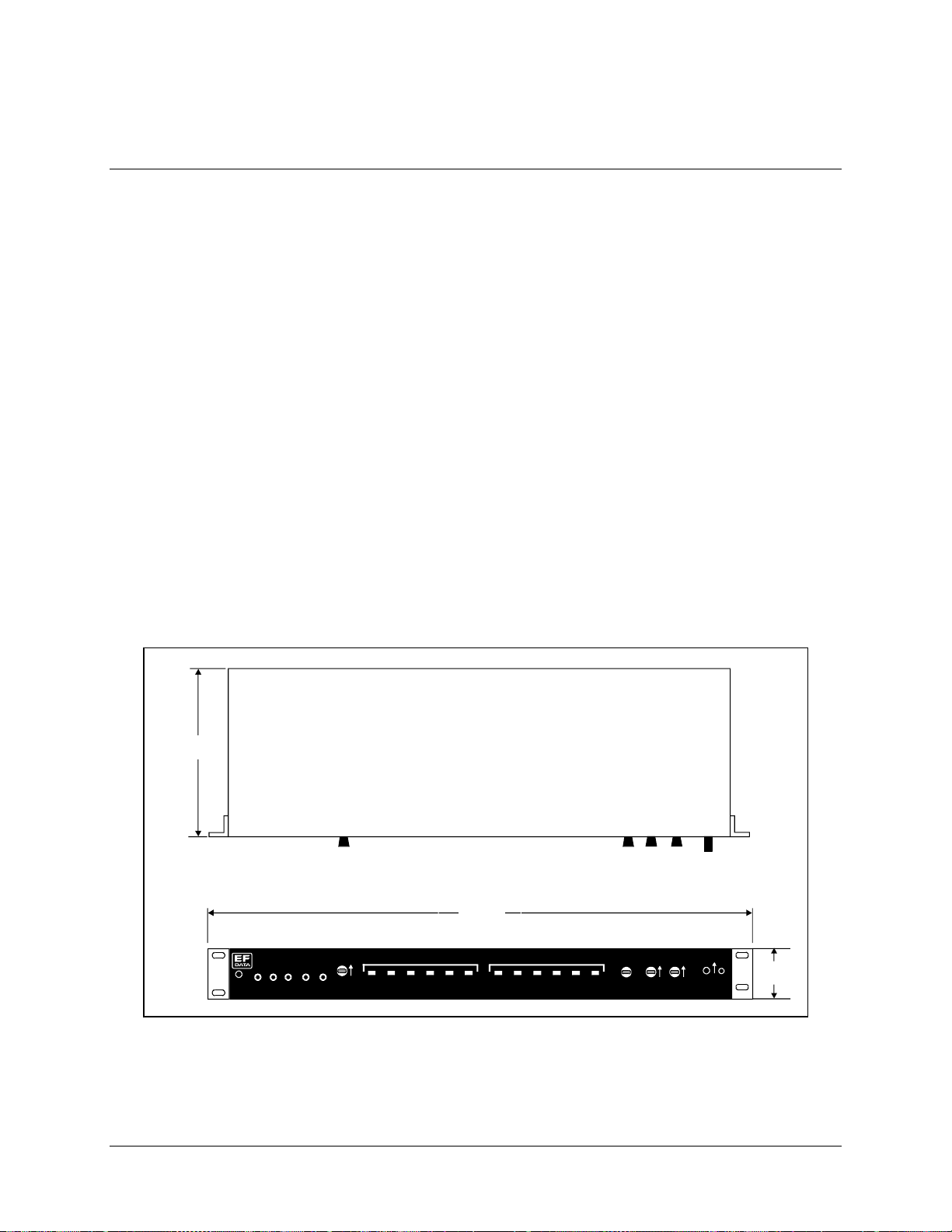
Single Thread System Installation High-Power TWTA Satellite Terminals
2.4 HPC-1200 Installation
2.4.1 Mechanical
Refer to Figure Chapter 2-8 for dimensional information. The controller can be rack- or
bench-mounted. The mounting brackets are removable.
Drawer slides are not required for rack installations. Mount the unit to the rack with the
mounting brackets supplied with the HPC-1200. The rubber feet are removable.
The following procedure assumes installation in a standard rack.
1. Verify that the rack will accept the unit. Refer to Figure Chapter 2-8 for
mounting dimensions.
2. Set the unit in place and secure it to the rack with screws and washers. (Rackmounting screws and washers are not supplied with the unit.)
6.54 in.
(
16.61 cm
)
GND +15VDC HELIX
TWTA CO NTROLLE R
Note:
All connections are made at the rear panel of the unit.
19.00 in.
(
)
48.26 cm
FAULTS STATUS
HIGH
TEMP BEAM
HELIX
VOLTAGE
ARC
LOCK
FAULT
POWER
STAND
FTDFAN
ON
BY
SELECTED ON
HV O NSUMMARY
FAN O N
CURRENTHVMONITOR
TEMP
ANALOG
LAMP TEST
ON
EXTERNAL
INTE R LO CK
REMOTE
LOCAL
HEATER
STANDBY
ON
HIGH
VOLTAG E
ON
AC
POW E R
1.61 in.
(
4.09 c m
)
Figure Chapter 2-8. HPC-1200 Outline Drawing
2–30 Rev.1
Page 77

High-Power TWTA Satellite Terminals Single Thread System Installation
)
2.4.2 External Connections
The HPC-1200 controller (Figure Chapter 2-9) provides for the following list of external
connections on the rear panel (Table Chapter 2-5):
Table Chapter 2-5. Rear Panel Connectors
Ref. Name Rear Panel Connector
J1 Remote Interfac e D-type, 25 pin, male
J2 ODU Monitor & Control D-type, 25 pin, female
Figure Chapter 2-9. HPC-1200 Rear Panel Connector Locations
2.4.2.1 External Interfaces (J1)
The HPC-1200 Remote Control Interface (J1) is MPS compatible. The interface
connector (J1) pinouts are described in Table Chapter 2-6 and shown in Figure Chapter
2-10.
All Control Command Inputs are static protected, opto-isolated inputs with internal pullup to +15V through 10k resistor. The external interlock is relay or switch contact closure
to the interlock return. All Status Indicator outputs are transient-protected, open collector
opto-isolated transistors with a minimum in-line series resistance of 100
J1 REM OTE CONTROL INTERFACE
REMOTE INTERFACE
J2 TO POW ER AMPLIFIER (FEMALE DB-25
J2J1
ODU MONITOR & CONTROL
.
Ω
Pins 4 and 5 must be connected to enable operation of the power supply. These pins have
been internally connected by the manufacturer.
Rev.1 2–31
Page 78

Single Thread System Installation High-Power TWTA Satellite Terminals
Table Chapter 2-6. Remote Control Interface Connector Pinouts
Type Pin # Function Return
Control Interfaces
(All circuits are
active LOW)
Digital Status Circuits
(All circuits are
active LOW)
Analog Status Circ uits 14
Output Voltage Circuits 1
High Voltage Select ON Control
2
High Voltage Select OFF Control
3
External Interlock (see Note below)
5
Fault Reset Control
6
High Voltage ON Status I ndic at or
8
Summary Fa ult I ndica t or
10
High Voltage Select ON Indicator
12
Standby Status Indica tor
21
FTD (Filament Tim e De lay)
23
Remote/Local Indicator
25
Helix Current Monitor
High Voltage Monitor
15
TWT Temperature Monitor
17
+24 Volts DC
19
+15 Volts DC
Ground 4, 16 Common Ground (connecte d) NA
Note:
Pin 5 is connected to Pin 4 with an internal jumper.
1
Pin #
4
4
4
4
7
22
24
9
11
13
16
16
16
16
16
13
Comment
Pin 4 tied to Pin 16.
Pins 7, 9,11, and 22 tied together.
May be interchanged.
Pin 16 tied to Pin 4.
14
TWTA REMOTE CONTROL INTERFACE CONNECTOR
MATING REMOTE CONTROL INTERFACE PLUG
(MALE) DB-25(M)
14 25
113
(FEMALE) DB-25(F)
25
Figure Chapter 2-10. Interface Connector Pinouts
2–32 Rev.1
Page 79

High-Power TWTA Satellite Terminals Single Thread System Installation
2.4.2.1.1 Control Interfaces
1. High Voltage Select ON (Pin 2). Momentarily connect Pin 2 to ground (Pin 4) to
latch the High Voltage Select relay in the ON state. Return = Pin 4.
2. High Voltage Select OFF (Pin 3). Momentarily connect Pin 3 to ground (Pin 4)
to release the latch of the High Voltage Select relay and set it to the OFF state.
Return = Pin 4.
3. External Interlock (Pin 5). This circuit is designed for normally closed operation
(Pin 5 connected to Pin 4). Opening this circuit disables High Voltage ON. Open
circuit voltage is 15 VDC. The circuit is current limited to less than 1 mA when
shorted. Return = Pin 4.
4. Fault Reset (Pin 6). Momentarily connect Pin 6 to ground (Pin 4) to reset latched
faults. Return = Pin 4.
Note:
Activating the Beam Select OFF command line, followed by activating the
Beam Select ON command line, will also clear latched faults.
2.4.2.1.2 Digital Status Circuits
The digital status interface circuits are isolated outputs as shown in Figure Chapter 2-11.
EXTERNAL CIRCUITS INTERNAL CIRCUIT S
Customer Supplied
Pull-Up Resistor
and 5-15 VDC
STATUS LINE
STATUS LINE
RETURN
Figure Chapter 2-11. Digital Status Circuit Isolation
Note:
The term “active = low” is used in the following paragraphs to indicate when a
condition is true and the status indicator is active (e.g., the photo-diode is conducting).
Pair of I/O
Connector
Pins for Each
Status Circuit
PHOTO-COUPLER
Rev.1 2–33
Page 80

Single Thread System Installation High-Power TWTA Satellite Terminals
1. High Voltage ON Indicator (Pin 8). (Active = low.) When active, indicates that
the amplifier is ON, i.e., the transistor is turned ON and the collector Pin 8 (+) is
pulled to the emitter (Pin 7). Maximum open voltage is 20V and maximum
switched current is 3 mA. The switch is an isolated photo-coupler.
Return = Pin 7.
2. Summary Fault Indicator (Pin 10). (Active = low.) When active, indicates there
is fault within the amplifier, i.e., the transistor is turned ON and the collector
Pin 10 (+) is pulled to the emitter (Pin 22). Maximum open voltage is 20V and
maximum switched current is 3 mA. The switch is an isolated photo-coupler.
Return = Pin 22.
3. The faults included are:
a. Helix Over-Current
b. High Voltage
c. Over-Voltage/Under-Voltage
d. Over-Current (Triggering HV Fault)
e. Power Supply Over-Temperature
4. High Voltage Select ON Indicator (Pin 12). (Active = low.) When active,
indicates the High Voltage ON command has been selected, i.e., the transistor is
turned ON and the collector Pin 12 (+) is pulled to the emitter (Pin 24).
Maximum open voltage is 20V and maximum switched current is 3 mA. The
switch is an isolated photo-coupler. Return = Pin 24.
5. Standby Indicator (Pin 21). (Active = low.) When active, indicates the unit is
ready for on-line service, i.e., the transistor is turned ON and the collector Pin 21
(+) is pulled to the emitter (Pin 9). Maximum open voltage is 20V and maximum
switched current is 3 mA. The switch is an isolated photo-coupler.
Return = Pin 9.
6. FTD (Filament Time Delay) Indicator (Pin 23). (Active = low.) When active,
indicates the Filament Time Delay cycle is in progress, i.e., the transistor is
turned ON and the collector Pin 23 (+) is pulled to the emitter (Pin 11).
Maximum open voltage is 20V and maximum switched current is 3 mA. The
switch is an isolated photo-coupler. Return = Pin 11.
7. Local/Remote Indicator (Pin 25). (Active = low.) When active, indicates the
front panel Local/Remote switch has been set to Remote, i.e., the transistor is
turned ON and the collector Pin 25 (+) is pulled to the emitter (Pin 13).
Maximum open voltage is 20V and maximum switched current is 3 mA. The
switch is an isolated photo-coupler. Return = Pin 13.
2–34 Rev.1
Page 81

High-Power TWTA Satellite Terminals Single Thread System Installation
2.4.2.1.3 Analog Status Circuits
1. Helix Current Monitor (Pin 14). The TWT’s helix current may be determined by
monitoring the voltage on Pin 14. There are 2 mA of current for each volt
measured. Return = Pin 16.
2. High Voltage Monitor (Pin 15). The high voltage level may be determined by
monitoring the voltage in Pin 15. This output (VDC) is proportional to the high
voltage (1000/1). Return = Pin 16.
3. TWT Temperature Monitor (Pin 17). The TWT collector temperature may be
determined by monitoring the voltage on Pin 17 and referring to the chart in
Figure 2-5. Return = Pin 16.
2.4.2.1.4 Output Voltage Circuits
1. +24 Volts (Pin 1). 24 VDC at 100 mA is available for external use.
2. +15 Volts (Pin 19). 15 VDC at 100 mA is available for external use or for
powering the control and status circuit indicators.
Rev.1 2–35
Page 82

Single Thread System Installation High-Power TWTA Satellite Terminals
2.4.2.2 ODU Monitor and Control (J2)
The discrete signal interface is defined with an M&C connection as described below in
Table 2-7. The pinouts are for the 25-pin D type female connector.
Table Chapter 2-7. M&C Connector Pinouts
Type Pin # Function
Control Commands
(All circuits are active low outputs)
Status Indicators, Digita l Inputs 1
Status Monitors, Analog I nputs 25
Input Voltage (Power ON Indic a tor )
Input Voltage (from TWT)
24
21
23
10
12
15
16
17
18
20
11
14
19
13
22
6
9
3
7
8
4
5
AC Power ON
High Voltage Enable
Heater Standby
Fault Reset
Control Common (T W T GND)
Helix/Arc Fault Latche d
Helix/Arc/Fault
Heater Timer Complete
TWT Temp Fault
High Voltage ON
Fan ON
High Voltage Fault
Fan ON High
Summary Fa ult
Fan Lock
Status RTN (HPC GND)
Reserved
Helix Current
High Voltage Monitor
TWT Temperature
+15 VDC (100 mA max.)
+24 VDC (100 mA max.)
VDC/Analog RTN (TWT GND)
N/A
2–36 Rev.1
Page 83

High-Power TWTA Satellite Terminals Single Thread System Installation
2.4.2.3 Prime Power
The HPC operates from DC voltage provided by the TWTA unit. This is the +15 VDC
and the +24 VDC output from the TWTA.
Rev.1 2–37
Page 84

Single Thread System Installation High-Power TWTA Satellite Terminals
This page is intentionally left blank.
2–38 Rev.1
Page 85

Chapter 3.
REDUNDANT SYSTEM
INSTALLATION
3
This chapter provides installation instructions for the HPCST-5000/-7000, and
HPKST-12000 high-power satellite terminals in a redundant system configuration. For
installation instructions for related system components (RFTs, RSUs, and LNA plates),
refer to the appropriate manual:
• CST-5000 C-Band Satellite Terminal Installation and Operation Manual
• CST-7000 C-Band Satellite Terminal (INSAT) Installation and Operation
Manual
• KST-12000 Ku-Band Satellite Terminal Installation and Operation Manual
• RSU-503 Redundancy Switch Unit Installation and Operation Manual
Rev. 1 3–1
Page 86

Redundant System Installation High-Power TWTA Satellite Terminals
High Voltage Hazards:
The TWTA utilizes high voltage that can be lethal if contacted. The
WARNING
TWTA should not be operated without its cover unless the user is
thoroughly familiar with its operation and experienced with high
voltage.
RF Radiation Hazards:
Prior to operation of the TWTA, ensure that all microwave connections
are securely fastened. Check that there is no microwave leakage from
them. Never operate the TWTA with an open waveguide. This amplifier
is capable of generating high power microwave radiation, which can
cause bodily harm.
Safety Summary:
Equipment of this nature has inherent hazards. Operator or service
technicians should have training on the TWTAs. When the TWTA’s
cover is removed, the high voltage power supply for the TWT has
multiple exposed high voltage points. Use extreme care when operating
the amplifier with its cover removed.
3.1 Unpacking
The redundant TWTA assembly is shipped as a unit in one crate.
Before unpacking the carton components, ensure that there is plenty of room around the
carton for workspace. A large table is recommended.
To remove the parts:
1. Remove the screws from the lid of the wooden crate, and remove the lid.
Because the redundant TWTA assembly is heavy, assistance may be
necessary to remove the unit from the box.
CAUTION
2. Unbolt the TWTA assembly and remove it from the crate.
3. Remove the remainder of the parts from the crate. Refer to Section 3.2.1 for a
parts breakdown.
Note:
Save the packing material for reshipment.
3–2 Rev 1
Page 87

High-Power TWTA Satellite Terminals Redundant System Installation
3.2 Inspecting the Equipment
1. Carefully check the TWTA assembly for damage incurred during shipment.
2. Carefully check the TWTA assembly against the packing list shipped with the
equipment to ensure that the shipment is complete. Refer to the following
paragraphs.
3.2.1 Included Parts
A typical TWTA system contains the following components.
Notes:
1. Parts are not drawn to scale.
2. Because each system can be custom ordered, it is beyond the scope of this
manual to provide the unlimited configuration possibilities.
Qty. Description Qty. Description
1 TWT amplifier assembly. 1 High-power TWTA Teminal System
Installation and Operation Manual.
1 Envelope containing the test data.
Notes:
1. C-band TWTAs (HPA-500, -700) utilize waveguide kit KT/5115.
2. The Ku-band HPA (HPA-1200) utilizes waveguide kit KT/2820.
Rev. 1 3–3
Page 88
Redundant System Installation High-Power TWTA Satellite Terminals
1 C-band waveguide connector kit (EFData Part # KT5115), which includes:
Qty. Description Qty. Description
1 Gasket — full-thickness.
1 Gasket — half-thickness.
EFData Part # FP/5195.
8 10-32 x 1” bolt.
EFData Part # 03P1097.
8 1/4” split lockwasher.
EFData Part # HW/10-SPLIT.
1 Ku-band waveguide connector kit (EFData Part # KT/2820), which includes:
Qty. Description Qty. Description
2 O-Ring, -024, BUNA, black.
EFData Part # 32P1037.
8 6-32 x 7/8” socket head cap screw.
EFData Part # HW/GKT-CPR137G.
16 #10 flat washer.
EFData Part # HW/10-FLT.
8 10-32 hex nut.
EFData Part # HW/10-32HEXNUT.
2 O-Ring, black neoprene.
EFData Part # 32P1039.
16 #6 flat washer.
EFData Part # HW/6-32X7/8SHCS.
8 #6 split lockwasher.
EFData Part # HW/6-SPLIT.
3–4 Rev 1
EFData Part # HW/6-FLT.
8 6-32 hex nut.
EFData Part # HW/6-32HEXNUT.
Page 89
High-Power TWTA Satellite Terminals Redundant System Installation
Note:
Depending on the type of installation, the proper cable kit (KT/5249-1, -2, -3, or -4) will be
supplied with the TWTA.
1 Cable kit (EFData Part # KT/5249-1), which includes:
Qty. Description Qty. Description
1 Cable assembly.
EFData Part # PL/5248.
1 Cable hardware kit.
This kit contains the following connectors:
CN/DSB09FSPT01
CN/DSB09H01
CN/DSB09MSPT01
CN/DSB15F01
CN/DSB15H01
CN/DSB15MSPT01
CN/DSB37H01
CN/DSB37M01
CN/MS-STPG41M 01
1 Cable assembly.
EFData Part # PL/5240-1.
EFData Part # KT/5249.
Rev. 1 3–5
Page 90

Redundant System Installation High-Power TWTA Satellite Terminals
1 Cable kit (EFData Part # KT/5249-2), which includes:
Qty. Description Qty. Description
1 Cable assembly.
1 Cable assembly.
EFData Part # PL/5122.
1 Cable hardware kit.
This kit contains the following connectors:
CN/DSB09FSPT01
CN/DSB09H01
CN/DSB09MSPT01
CN/DSB15F01
CN/DSB15H01
CN/DSB15MSPT01
CN/DSB37H01
CN/DSB37M01
CN/MS-STPG41M 01
EFData Part # KT/5249.
1 Cable kit (EFData Part # KT/5249-3), which includes:
Qty. Description Qty. Description
1 Cable assembly.
EFData Part # PL/5240.
2 Cable assembly.
EFData Part # PL/5122-1.
1 Cable hardware kit.
This kit contains the following connectors:
CN/DSB09FSPT01
CN/DSB09H01
CN/DSB09MSPT01
CN/DSB15F01
CN/DSB15H01
CN/DSB15MSPT01
CN/DSB37H01
CN/DSB37M01
CN/MS-STPG41M 01
EFData Part # KT/5249.
3–6 Rev 1
EFData Part # PL/5240.
Page 91

High-Power TWTA Satellite Terminals Redundant System Installation
1 Cable kit (EFData Part # KT/5249-4), which includes:
Qty. Description Qty. Description
1 Cable assembly.
EFData Part # PL/5248.
1 Cable hardware kit.
This kit contains the following connectors:
CN/DSB09FSPT01
CN/DSB09H01
CN/DSB09MSPT01
CN/DSB15F01
CN/DSB15H01
CN/DSB15MSPT01
CN/DSB37H01
CN/DSB37M01
CN/MS-STPG41M 01
2 Cable assembly.
EFData Part # PL/5240.
EFData Part # KT/5249.
1 Cable kit (EFData Part # KT/5124), which includes:
Qty. Description Qty. Description
1 Cable assembly.
EFData Part # PL/5124.
1 Cable hardware kit.
This kit contains the following connectors:
CN/CRC39S20RC01
CN/MS-STPG32M 01
CN/STPG26M01
EFData Part # KT/5124.
1 Cable assembly.
EFData Part # PL/5240.
Rev. 1 3–7
Page 92
Redundant System Installation High-Power TWTA Satellite Terminals
1 Hardware kit (EFData Part # KT/5125), which includes:
Qty. Description Qty. Description
2 Unistrut — 14” long.
8 5/16-18 x 1.25” bolt.
EFData Part # FP/3595.
Used for round and square pole mount only.
8 Pipe block.
EFData Part # HW/BLK-PIPE2-8.
Used for round pole mount only.
4 Threaded rod, 5/16-18 x 14”.
EFData Part # HW/RD5/16-18X14.
Used for round and square pole mount only.
8 Flat fitting plate, 5/16”.
EFData Part # HW/FIT-PLT-5/16.
12 5/16-18 spring nut.
EFData Part # HW/5/16-18SPNUT.
EFData Part # HW/5/16-18X1.25BLT.
20 5/16” split lockwasher.
EFData Part # HW/5/16-SPLIT.
20 5/16” flat washer.
EFData Part # HW/5/16-FLT.
12 5/16-18 hex nut.
EFData Part # HW/5/16-18HEXNT.
3–8 Rev 1
Page 93

High-Power TWTA Satellite Terminals Redundant System Installation
3.3 TWTA Installation
At the customer’s discretion, the TWTAs can be installed anywhere on or near the
antenna. The supplied hardware allows the installer a wide range of installation
alternatives, including:
• Vertical pole (e.g., mast) (either square or round). This is the most typical
installation.
• Within the hub of a large antenna.
EFData recommends that the TWTAs be mounted vertically.
Note:
A clearance of 2” (5.08 cm) is required for the air inlets and exhaust ports. If the
TWTA is mounted in an enclosed chamber, duct the exhaust air to the outside of the
chamber. Do not re-circulate the exhaust air back into the TWTA. Use an exhaust duct
that is slightly larger than the exhaust port of the TWTA and one that has smooth bends
and transitions.
Rev. 1 3–9
Page 94

Redundant System Installation High-Power TWTA Satellite Terminals
3.3.1 Tools Required
Qty. Description
1
3/8” drive ratchet.
1
3” x 3/8” drive extension.
1
7/16” x 3/8” drive socket. (Metric equivalent: 12mm , 6 pt.)
1
½” x 3/8” drive socket. (Metric equivalent: 13mm, 6 pt.)
1 ½” combination wrench. (Metric equivalent: 13m m com bination
wrench with a 6 pt. Box end.)
1 7/64” hex key (allen w rench). (N o m etric equivalent.)
1 5/16” combination wrench. (M etric equivalent: 8m m com bination
wrench with a 6 pt. Box end.)
3–10 Rev 1
Page 95

High-Power TWTA Satellite Terminals Redundant System Installation
3.3.2 Vertical Pole Installation
3.3.2.1 Round Pole
Note:
The following process is for a typical installation. Custom systems may be
ordered, and are beyond the scope of this manual.
To install the TWTA to a round vertical pole:
1) Install the pipe blocks as follows:
a) Install two spring nuts in each of four 14” unistruts (the two on the TWTA,
and two additional).
Be sure to position the spring nuts in the unistruts wide enough apart so that
when the pipe blocks are installed, they will clear the pole when the unit is
lifted into place for installation.
b) Install each spring nut as follows:
(1) Place the spring nut in the unistrut channel, spring side down, with its
wide side parallel with the unistrut channel.
(2) Press down on
the spring nut to
compress the
spring, and rotate
the nut 90° (i.e.,
perpendicular to
the unistrut).
(3) Release pressure
on the spring nut.
(4) Repeat Steps 1.b.(1) through 1.b.(3) for each spring nut.
c. Using four 5/16-18 bolts, 5/16” split lockwashers, and 5/16” flat washers,
loosely secure the pipe blocks to the spring nuts.
Rev. 1 3–11
Page 96

Redundant System Installation High-Power TWTA Satellite Terminals
2. Install the threaded rods as follows:
a. Install two spring nuts in both 14” unistruts mounted on the TWTA.
Note:
Ensure the spring nuts are positioned over the outer holes in the 14”
unistruts.
b. To install each spring nut:
(1) Place the spring nut in the unistrut channel, spring side down, with its
wide side parallel with the unistrut channel.
(2) Press down on
the spring nut to
compress the
spring, and rotate
the nut 90° (i.e.,
perpendicular to
the unistrut).
(3) Release pressure
on the spring nut.
(4) Repeat Steps 2.b.(1) through 2.b.(3) for each spring nut.
c. Thread a 5/16-20 nut approximately 1-1/2” onto each threaded rod. (This
will ensure that the threaded rods will extend beyond the spring nuts when
installed.)
d. Place a 5/16” split
lockwasher, 5/16” flat
washer, and flat fitting
plate over each
threaded rod.
3–12 Rev 1
Page 97

High-Power TWTA Satellite Terminals Redundant System Installation
e. One threaded rod at a
time, hold the washers
and plate in place on
the rod, and screw the
rod into a spring nut.
Notes:
1. Be sure to position the flanges of the flat fitting plates in the grooves
of the unistruts.
2. Before tightening the nuts on the threaded rods, ensure that the end
of each rod is screwed in until it is flush with the backside of the
unistrut. This ensures the rods are threaded completely through the
spring nuts.
f. Thread a 5/16-18 nut
about 2” onto the end
of each threaded rod.
g. Slip a 5/16” split
lockwasher, 5/16” flat
washer, and flat fitting
plate (in that order)
onto each threaded
rod.
Rev. 1 3–13
Page 98

Redundant System Installation High-Power TWTA Satellite Terminals
3. Mount the TWTA as follows:
a. Lift the TWTA into position on the vertical pole.
b. Slip a 14” unistrut over each of pair of threaded rods (upper and lower).
Note:
Install the 14” unistruts with the open face toward the pole.
c. Install a 5/16” flat
washer, 5/16” split
lockwasher, and 5/1618 nut on each
threaded rod.
d. Position the TWTA as
e. Slide the pipe blocks
3.3.2.2 Square Pole
For square vertical pole installation, follow the steps in Section 3.3.2.1, with the
following exceptions:
• Do not perform Step 1.
• Do not perform Step 3.e.
desired, and tighten
the 5/16-18 nuts
installed in Step 3.c.
inward until they
contact the vertical
pole, then firmly
tighten the 5/16-18
bolts.
3.3.3 Spar Mount
There is no spar mount option with redundant TWTAs.
3–14 Rev 1
Page 99

High-Power TWTA Satellite Terminals Redundant System Installation
3.3.4 External Connections
Refer to Chapter 2, Section 2.3.4, for information on connections between the TWTA
and other equipment.
3.3.4.1 System Interface Wiring
Note:
In all cable drawings (Figures 3-1 through 3-4), a set of double UPPERCASE
letters (e.g., “AA”) corresponds to a small letter (e.g., “a”) on the cable connector.
Refer to Figure 3-1 for the system interface wiring between the TWTA, RFT, and RSU
for a redundant system.
Refer to Figure 3-2 for a schematic of the customer interface cable. This cable is not
included with TWTA systems, and must be ordered separately from EFData. (If the
customer has an M&C system, this illustration is typical.)
Refer to Figure 3-3 for a schematic of the uplink-only cable.
Rev. 1 3–15
Page 100

Redundant System Installation High-Power TWTA Satellite Terminals
Figure 3-1. HPCST/KST 1:1 Redundant System Cable Harness (CA/5122)
3–16 Rev 1
 Loading...