

Page 1

Comtech EF Data is an
AS9100 Rev B / ISO9001:2000 Registered Company
FX Series
Administrator Guide
Version 6.1.1
IMPORTANT NOTE: The information contained in this document supersedes all previously published information
regarding this product. Product specifications are subject to change without prior notice.
MN-FXSERIESADM6 Revision 5
Page 2

Comtech EF Data / Stampede
FX Series Administration Guide - Version 6.1.1 ii
Chapter: Using This Document
Section: <Table of Contents MN-FXSERIESADM6 Rev 5
Page 3

Comtech EF Data / Stampede
Table of Contents
Table of Contents ......................................................................................... iii
Table of Figures .......................................................................................... viii
Using This Document........................................................................ x
Document Organization ................................................................................... x
Contacting Product Support ............................................................................. xi
FX Series End User License Agreement ................................................................ xii
Patents and Trademarks ................................................................................ xiv
Conventions and References ............................................................................ xv
Comtech EF Data Warranty Policy ..................................................................... xvi
Release Notes ........................................................................................... xviii
Version 6.1.1 Functionality Enhancements ................................................... xviii
Version 6.1 Functionality Enhancements ...................................................... xviii
Version 6.0.3 Functionality Enhancements ..................................................... xix
Version 6.0.2 Functionality Enhancements ...................................................... xx
Version 6.0.1 Functionality Enhancements ...................................................... xx
1 Overview - FX Series .............................................................. 22
1.1 Stampede FX Series Product Line Update ................................................... 22
1.2 Technologies that Optimize Satellite Bandwidth Acceleration.......................... 23
1.3 Single-Sided Solution ........................................................................... 25
1.3.1 Load Balancing via WCCP .................................................................. 25
1.3.2 Source IP Preservation ..................................................................... 25
1.3.3 Connection Management .................................................................. 26
1.3.4 QoS with ACM option ....................................................................... 26
1.3.5 GZIP Compression ........................................................................... 26
1.3.6 Image Reduction and Smoothing ......................................................... 27
1.3.7 Static Caching ............................................................................... 27
1.3.8 TCP Optimization ........................................................................... 28
1.4 Two-Sided Solution .............................................................................. 29
1.4.1 Cache Differencing ......................................................................... 29
1.4.2 Multiplexing of Large Data Objects ...................................................... 29
1.4.3 MicrosoftTM Update Caching .............................................................. 30
1.4.4 Network Protocol Optimization .......................................................... 30
1.4.5 Dynamic Data Deduplication .............................................................. 30
1.4.6 Header Compression/Packet Aggregation .............................................. 30
1.4.7 Multicator .................................................................................... 31
1.5 FX Series ADC Appliance ....................................................................... 32
1.5.1 Theory of Operation ........................................................................ 32
1.5.2 Reporting ..................................................................................... 32
1.5.3 Deployment Options ........................................................................ 32
1.6 FX Series Remote Appliance ................................................................... 33
1.6.1 Theory of Operation ........................................................................ 33
1.6.2 TCP Optimization and Data Compression ............................................... 33
1.6.3 Reporting ..................................................................................... 34
1.6.4 Deployment Options ........................................................................ 34
1.7 Mesh Networking with the FX Series ......................................................... 35
1.7.1 Theory of Operation ........................................................................ 35
1.7.2 Mesh Capability with two FX Series appliances at each node ....................... 35
1.8 FX Series Appliances Data Sheet .............................................................. 38
FX Series Administration Guide - Version 6.1.1 iii
Chapter: Using This Document
Section: <Table of Contents MN-FXSERIESADM6 Rev 5
Page 4

Comtech EF Data / Stampede
1.8.1 Single Sided with the Application Delivery Controller (ADC) ........................ 38
1.8.2 Two Sided with the ADC and the Remote .............................................. 38
1.8.3 FX Series Hardware Specification ........................................................ 39
1.8.4 FX-4010 Physical Description ............................................................. 40
1.8.5 FX-1005 Physical Description ............................................................. 41
1.8.6 FX-1010 Physical Description ............................................................. 43
1.8.7 Hardware Mounting Options for FX Series FX-1005 ................................... 45
2 Pre-Installation Information ...................................................... 46
2.1.1 Unpacking .................................................................................... 46
2.1.2 User Interfaces .............................................................................. 46
2.1.3 Documentation .............................................................................. 47
2.2 Configure Appliance Management Address – All Installation Patterns ................. 47
3 FX Series Network Installation Patterns ......................................... 48
3.1 FX Series Installation Pattern (In-Path Bridged) ........................................... 48
3.1.1 Cable the Appliance ........................................................................ 48
3.1.2 Configure the Appliance ................................................................... 48
3.2 FX Series Installation Pattern (Routed) ...................................................... 49
3.2.1 Cable the Appliance ........................................................................ 49
3.2.2 Configure the Appliance ................................................................... 49
3.3 FX Series Installation Pattern (WCCP) ....................................................... 50
3.3.1 Cable the Appliance ........................................................................ 50
3.3.2 Configure the Appliance ................................................................... 50
3.4 Installation of Two FX Series Appliances in a Mesh Configuration ...................... 52
3.4.1 Configure the appliances .................................................................. 52
3.4.2 Mesh installation with Redundancy capability ......................................... 52
4 FX Series Network Settings ....................................................... 53
4.1 Standard Network Configuration Overview ................................................. 53
4.2 Basic Network Interfaces ....................................................................... 55
4.2.1 Management Interface ..................................................................... 55
4.2.2 Auxiliary Interface .......................................................................... 56
4.2.3 Management Static Routes ................................................................ 56
4.3 Host Settings ..................................................................................... 57
4.3.1 Host Networking Settings .................................................................. 57
4.3.2 Host File Entries ............................................................................. 58
4.4 In-Path Interface ................................................................................ 59
4.4.1 In-Path Interface Definition ............................................................... 59
4.5 LAN Interfaces ................................................................................... 61
4.5.1 LAN Interface Definition ................................................................... 61
4.5.2 Configure SNMP Settings ................................................................... 62
4.6 Configuring Quality of Service with ACM .................................................... 64
4.6.1 Overview ..................................................................................... 64
4.6.2 Configure Dynamic ACM Parameters ..................................................... 65
4.6.3 QoS Filter Definitions....................................................................... 68
4.6.4 QOS Queue Definitions ..................................................................... 70
4.7 FX Series Multicator Overview ................................................................ 73
4.7.1 Theory of Operation ........................................................................ 74
4.7.2 Multicator Settings .......................................................................... 75
4.7.3 Multicator General Setup (required for all roles) ..................................... 77
4.7.4 Multicator Controller Configuration Setup ............................................. 78
4.7.5 Multicator Receiver Configuration Setup ............................................... 78
FX Series Administration Guide - Version 6.1.1 iv
Chapter: Using This Document
Section: <Table of Contents MN-FXSERIESADM6 Rev 5
Page 5

Comtech EF Data / Stampede
4.7.6 Multicator Transmitter Configuration Setup ........................................... 78
4.8 Redundancy....................................................................................... 79
4.8.1 Redundancy Configuration Settings ...................................................... 79
4.8.2 Configuring Key-Exchange ................................................................. 80
4.8.3 Example 1:1 redundancy with fail over setup scenario .............................. 81
4.8.4 Synchronizing Configurations in a WCCP Cluster ...................................... 82
4.9 WCCP .............................................................................................. 83
4.9.1 WCCP Configuration Considerations ..................................................... 84
4.9.2 WCCP Cisco Device configuration ........................................................ 84
4.9.3 Web Cache Communication Protocol Parameters ..................................... 84
4.9.4 WCCP Router Configuration and Status Monitoring ................................... 86
4.9.5 WCCP IP Spoofing Configuration for Routers ........................................... 87
4.9.6 WCCP IP Spoofing Configuration for Switches ......................................... 89
4.9.7 LAN and In-Path Interface Requirements for WCCP .................................. 90
4.9.8 Configuring WCCP on earlier models .................................................... 90
5 FX Series ADC Specific Settings ................................................... 91
5.1 Overview .......................................................................................... 91
5.1.1 General Settings ............................................................................. 92
5.1.2 Object Retrieval Logging .................................................................. 93
5.1.3 Traffic Interception......................................................................... 93
5.1.4 System Time ................................................................................. 94
5.1.5 Software Updates ........................................................................... 94
5.1.6 Administration ............................................................................... 94
5.1.7 Other .......................................................................................... 94
5.2 Port Definitions .................................................................................. 95
5.2.1 In-Path Interface: ........................................................................... 95
5.2.2 Example Port Definitions .................................................................. 96
5.2.3 Setting up an HTTP Forward Proxy ...................................................... 96
6 FX Series Remote Specific Settings ............................................... 97
6.1 FX Remote Settings Overview ................................................................. 97
6.2 FX Series Remote Configuration Settings .................................................... 98
6.2.1 FX Series Remote General Settings ...................................................... 99
6.2.2 System Time ................................................................................. 99
6.2.3 Traffic Interception......................................................................... 99
6.2.4 Administration ............................................................................. 100
6.2.5 Other ........................................................................................ 100
6.2.6 Configuration Notes ...................................................................... 101
6.3 FX Series Remote In-Path Interfaces ....................................................... 102
6.3.1 Best Practices for Routed Mode Configurations ..................................... 102
6.3.2 Add In-Path Interfaces ................................................................... 102
7 FX Series Status ................................................................. 105
7.1 FX Series ADC Status .......................................................................... 105
7.1.1 FX Series ADC Real-Time Monitor ...................................................... 105
7.2 QOS Status Monitor ............................................................................ 108
7.2.1 QOS Status Monitor Options ............................................................. 108
7.2.2 QOS Status Matrix ......................................................................... 109
7.2.3 Modem Status: ............................................................................. 111
7.2.4 Output Data Rate: ........................................................................ 111
7.2.5 FX Series ADC Current Statistics ........................................................ 112
7.3 FX Series Remote Status ..................................................................... 116
FX Series Administration Guide - Version 6.1.1 v
Chapter: Using This Document
Section: <Table of Contents MN-FXSERIESADM6 Rev 5
Page 6

Comtech EF Data / Stampede
7.3.1 FX Series Remote Real-Time Monitor .................................................. 116
7.3.2 FX Series Remote Current Status Reports ............................................ 118
8 FX Series Optimization Settings ................................................ 120
8.1 Configure Application Policies .............................................................. 120
8.1.1 FX Series Optimization Summary ....................................................... 121
8.1.2 Single-Sided Optimizations: ............................................................. 121
8.1.3 Two-sided Optimizations ................................................................ 121
8.1.4 Authorization Realms ..................................................................... 122
8.1.5 Web Application Policies ................................................................ 124
8.1.6 Authorization realm ...................................................................... 125
8.1.7 Enable Acceleration ...................................................................... 125
8.1.8 Caching ..................................................................................... 125
8.1.9 Content Validation ........................................................................ 125
8.1.10 Image Optimization ..................................................................... 126
8.1.11 Back-End Server Interface Options ................................................... 127
8.1.12 When Application Policies Take Effect: ............................................. 127
8.2 Web Application Firewall Features ......................................................... 128
8.2.1 Buffer Overflow Prevention: ............................................................ 128
8.3 Setting up Basic Web Application Policies ................................................ 129
8.3.1 How to Set the Policy Header .......................................................... 129
8.3.2 Set Specific Users Access ................................................................ 130
8.3.3 Restrict acceleration for specific sites, or users .................................... 131
8.3.4 Set Specific Optimization Techniques ................................................. 131
8.4 Layer 5 Application Policies ................................................................. 132
8.4.1 Certified Applications .................................................................... 132
8.4.2 Configuring Other Applications ......................................................... 132
8.4.3 Configuring Layer 5 Optimizations ..................................................... 133
8.4.4 Layer 5 Protocols .......................................................................... 134
8.4.5 ToS handling method ..................................................................... 134
8.4.6 Layer 5 Acceleration - Theory of Operation .......................................... 135
9 FX Series Operations Features .................................................. 136
9.1 Basic Operations Functions .................................................................. 137
9.1.1 Backup/Restore Configuration Files ................................................... 137
9.1.2 Disaster Recovery Procedure ........................................................... 137
9.1.3 Change Password .......................................................................... 138
9.1.4 Manage Licenses / Fast Codes .......................................................... 138
9.1.5 Shutdown/Restart Appliance ........................................................... 139
9.2 Packet Capture ................................................................................ 140
9.3 Update Software ............................................................................... 142
9.3.1 Upload and Apply Server Installation Image Version 6.02+: ....................... 142
9.3.2 Download and Apply Image from ADC (FX Remote Only): ......................... 142
9.3.3 Software Update Discussion ............................................................. 142
9.3.4 Recommended Process for Software Upgrades ...................................... 143
9.4 Updating FX Series Appliance Software at 5.78.0 or earlier ........................... 144
9.4.1 Base Platform Image (BPI) Upgrade Process ......................................... 144
9.4.2 Upgrade Kit and Prep .................................................................... 144
9.4.3 The Upgrade Process ..................................................................... 144
9.5 Updating FX Series Appliance Software to Version 6.1 ................................. 146
9.5.1 User Interfaces ............................................................................ 146
9.5.2 Determine the Current Software Version ............................................. 146
9.5.3 Screen print version information for reference ..................................... 146
9.5.4 Determine the Available Upgrade Versions .......................................... 147
FX Series Administration Guide - Version 6.1.1 vi
Chapter: Using This Document
Section: <Table of Contents MN-FXSERIESADM6 Rev 5
Page 7

Comtech EF Data / Stampede
9.5.5 Download the files to your desktop or other convenient location. .............. 147
9.5.6 Check for new software: ................................................................ 147
9.5.7 Installing the Latest Software Version ................................................ 147
9.5.8 Install the FX Platform Image Update ................................................. 147
9.5.9 Upload and Apply FX Platform Image Update: ....................................... 147
9.5.10 Verify Update Success .................................................................. 148
9.6 FX Series Documentation ..................................................................... 149
9.6.1 On the Comtech EF Data web site: .................................................... 149
9.6.2 On the appliance: ......................................................................... 149
10 Appendix ........................................................................ 150
10.1 FX Series Console Management Functions ................................................. 150
10.1.1 Main Menu ................................................................................ 150
10.1.2 Configure Appliance ..................................................................... 150
10.1.3 Show Status ............................................................................... 151
10.1.4 Diagnose Network Connectivity ....................................................... 151
`
FX Series Administration Guide - Version 6.1.1 vii
Chapter: Using This Document
Section: <Table of Contents MN-FXSERIESADM6 Rev 5
Page 8

Comtech EF Data / Stampede
Table of Figures
Figure 1-1 FX Series Multicator Theory of Operation ....................................................................... 31
Figure 1-2 FX Series Basic Mesh Connectivity Diagram ..................................................................... 35
Figure 1-3 FX Series Hub Spoke Mesh Connectivity Diagram ............................................................... 36
Figure 1-4 FX Series Mesh with Redundancy Connectivity Diagram........................................................ 37
Figure 1-5 FX Series Appliances Data Sheet .................................................................................. 38
Figure 1-6 FX Series Hardware Specifications ................................................................................ 39
Figure 1-7 FX Series FX-4010 Back Panel ..................................................................................... 40
Figure 1-8 FX Series FX-1005 Front Panel .................................................................................... 41
Figure 1-9 FX Series FX-1005 Rear Panel ..................................................................................... 42
Figure 1-10 FX Series FX-1010 Front Panel ................................................................................... 43
Figure 1-11 FX Series FX-1010 Rear Panel .................................................................................... 44
Figure 3-1 FX Series Mesh Connection Diagram ............................................................................. 52
Figure 4-1 FX Series Standard Configuration Screen ........................................................................ 53
Figure 4-2 FX Series Basic Network Interfaces Screen ....................................................................... 55
Figure 4-3 FX Series Host/DNS Settings Screen .............................................................................. 57
Figure 4-4 FX Series In-Path Interfaces Definition Screen ................................................................... 59
Figure 4-5 FX Series LAN Interfaces Screen .................................................................................. 61
Figure 4-6 FX Series SNMB Configuration Screen ............................................................................ 63
Figure 4-7 FX Series Quality of Service Menu ................................................................................ 64
Figure 4-8 FX Series Dynamic ACM Configuration Screen ................................................................... 65
Figure 4-9 FX Series ACM QOS Status by VSAT Modem Screen ............................................................. 67
Figure 4-10 FX Series QoS Filters Configuration Screen ..................................................................... 68
Figure 4-11 FX Series Quality of Service Queues ............................................................................ 70
Figure 4-12 FX Series Q0S Queues Configuration Screen ................................................................... 71
Figure 4-13 FX Series Multicator Theory of Operation ...................................................................... 74
Figure 4-14 FX Series Multicator Configuration Screen (Controller Settings) .............................................. 75
Figure 4-15 FX Series Multicator Transmitter/Receiver Configuration Settings ........................................... 76
Figure 4-16 FX Series Redundancy Screen ................................................................................... 79
Figure 4-17 FX Series ADC WCCP Definitions Screen ........................................................................ 83
Figure 5-1 FX Series ADC Configuration Menu ............................................................................... 91
Figure 5-2 FX Series ADC General Settings Screen ........................................................................... 92
Figure 5-3 FX Series ADC Port Definitions Screen ........................................................................... 95
Figure 6-1 FX Series Remote Main Index Screen ............................................................................ 97
Figure 6-2 FX Series Remote Configuration Screen .......................................................................... 98
Figure 6-3 FX Series Remote General Settings Screen....................................................................... 99
Figure 6-4 FX Series Remote In-Path Interfaces Screen .................................................................... 102
Figure 7-1 FX Series Status Menu............................................................................................ 105
Figure 7-2 FX Series ADC Real-Time Monitor Screen ....................................................................... 105
Figure 7-3 FX Series QOS Status Monitor Screen ........................................................................... 108
Figure 7-4 FX Series ADC Current Status Screen ............................................................................ 112
Figure 7-5 FX Series Remote Real-Time Monitor Screen ................................................................... 116
Figure 7-6 FX Series Remote Current Status Screen ........................................................................ 118
Figure 8-1 FX Series ADC Features Menu ................................................................................... 120
Figure 8-2 FX Series ADC Application Policy Menu ......................................................................... 120
Figure 8-3 FX Series Application Policy Applicability ....................................................................... 129
Figure 8-4 FX Series Authorization Realm Screen .......................................................................... 130
Figure 8-5 FX Series Specific Optimization Techniques Configurations ................................................... 131
Figure 8-6 FX Series Layer 5 Policy Configuration Screen .................................................................. 132
Figure 8-7 FX Series TCP/UDP Ports Table .................................................................................. 135
FX Series Administration Guide - Version 6.1.1 viii
Chapter: Using This Document
Section: Table of Figures MN-FXSERIESADM6 Rev 5
Page 9

Comtech EF Data / Stampede
Figure 9-1 FX Series Operations Menu ...................................................................................... 136
Figure 9-2 FX Series Backup and Restore Screen ........................................................................... 137
Figure 9-3 FX Series Change Passwords Screen ............................................................................. 138
Figure 9-4 FX Series Upgrade Fast Codes Screen ........................................................................... 138
Figure 9-5 FX Series Shutdown/Restart Appliance Screen ................................................................. 139
Figure 9-6 FX Series Packet Capture Screen ................................................................................ 140
Figure 9-7 FX Series Update Software Screen .............................................................................. 142
Figure 9-8 FX Series Software Version Display Screen ..................................................................... 146
FX Series Administration Guide - Version 6.1.1 ix
Chapter: Using This Document
Section: Table of Figures MN-FXSERIESADM6 Rev 5
Page 10

Comtech EF Data / Stampede
Using This Document
This guide was prepared to assist you in the installation, configuration and management of the FX Series Appliances.
This document contains the same information that is available thru the on-line help contained with the FX Series web
based administrative screens. This document supports Release 6.1 of FX Series Appliances.
Document Organization
Release Notes
This section delineates the major changes from the prior release.
Theory of Optimization
This section discusses the characteristic of data transmission that will cause slow response and higher
bandwidth requirements. It also delineates techniques that can reduce the slowness and help reduce
bandwidth requirements.
FX Series Technology
This section provides a brief description of the hardware and optimization techniques available through the
FX Series of appliances.
FX Series Installation Patterns
This section provides instruction on how to install the available configurations for all FX Series appliances.
FX Series Basic Network Settings
This section discusses how to set the basic networking parameters, such as Management Interface, Host
Settings, SNMP Settings, Multication, Quality of Service and High Availability.
FX Series ADC Specific Network Settings and Performance
This section discusses ADC specific network settings and current performance status, including General
Settings, In-Path Settings and WCCP.
FX Series Optimization
This section discusses optimization issues and definitions of optimization techniques available on the FX
Series appliances for web based or enterprise applications.
FX Series Remote Specific Network Settings and Performance
This section discusses Remote specific network settings and current performance status, including General
Settings and In-Path Settings.
FX Series Operations
This section discusses tools to perform operational tasks, including Backups, License Management,
Shutdown/Restart, and Updating Software for all FX Series Appliances. This section also describes how to
obtain FX Series documentation downloads for the FX Series Appliances.
Symbols used in this manual: Important Note Informational Note
FX Series Administration Guide - Version 6.1.1 x
Chapter: Using This Document
Section: Document Organization MN-FXSERIESADM6 Rev 5
Page 11

Comtech EF Data / Stampede
Contacting Product Support
Comtech EF Data Product Support representatives for FX Series Products are available. For all
product support, please call:
+1.240.243.1880
+1.866.472.3963 (toll free USA)
Comtech EF Data offers an annual subscription plan providing unlimited telephone support for the coverage
period, software upgrades and other important support provisions. Contact Technical Support for more
information.
FX Series Administration Guide - Version 6.1.1 xi
Chapter: Using This Document
Section: Contacting Product Support MN-FXSERIESADM6 Rev 5
Page 12

Comtech EF Data / Stampede
FX Series End User License Agreement
This is a legal agreement between you (either an individual or an entity) and Comtech EF Data Corporation.
HARDWARE LICENSE and WARRANTY
This product is covered by Comtech EF Data’s standard H/W warranty
SOFTWARE LICENSE
This SOFTWARE is protected by the copyright laws of the United States and international copyright treaties as
well as other intellectual property laws and treaties. This SOFTWARE product is licensed not sold.
The FX Series Appliance SOFTWARE you have licensed is defined as the SOFTWARE which operates on an
appliance. The FX Series Client SOFTWARE you have licensed is defined as the SOFTWARE whic h operates on
an intelligent, single computer, for use in accessing and accelerating Web, Browser or TCP-based
applications.
GRANT OF LICENSE: You have the right to install the FX Series Appliance SOFTWARE on all appliances for
which you have licensed copies. For each copy of the FX Series Client SOFTWARE this license confers you
have the right to install the SOFTWARE on a designated computer for use in accessing and accelerating Web,
Browser or TCP-based applications. The SOFTWARE is in “use” on a computer when it is loaded into
temporary memory (i.e. RAM) or installed into permanent memory (e.g., hard disk, CD-ROM, or other storage
device) of that computer. You may not install the SOFTWARE on more appliances or on more computers
than you have licensed copies.
Additionally, you have the right to make one (1) archival copy of the SOFTWARE for each appliance and for
each computer which has the SOFTWARE installed in accordance with the terms of this Agreement and
subject to the Use Restrictions as set forth below. The copyright notice, as contained in the original CD-ROM,
must be affixed to any archival copy.
COPYRIGHT: The SOFTWARE is owned by Comtech EF Data Corporation or its suppliers and is protected by
United States copyright laws and international treaty provisions. Therefore, you must treat the SOFTWARE
like any other copyrighted material (e.g., a book or musical recording). You may not copy any of the written
materials accompanying the SOFTWARE.
OTHER RESTRICTIONS: You may not rent, lease or sublicense the SOFTWARE, but you may transfer the
SOFTWARE and accompanying written materials on a permanent basis provided you retain no copies and the
recipient agrees to the terms of this Agreement. You may not modify, create a derivative work, reverse
engineer, decompile, or disassemble the SOFTWARE. If the SOFTWARE is an update or has been updated,
any transfer must include the most recent update and all prior versions. This license and your right to use
the SOFTWARE automatically terminate if you fail to comply with any provision of this license agreement.
SUPPORT AND UPGRADES: This Agreement does not entitle Licensee to any support, upgrades, patches,
enhancements or fixes for the Product (collectively, "Support"). Licensee must make separate arrangements
for Support and pay any fees associated with such Support. Any software upgrades, patches, enhancements
or fixes provided as part of Support for the Software that may be made available by Comtech EF Data’s
Maintenance agreement shall become part of the Software and subject to this Agreement.
LIMITED WARRANTY
LIMITED WARRANTY: Comtech EF Data warrants that (a) the SOFTWARE will perform substantially in
accordance with the accompanying written materials for a period of ninety (90) days from the date of receipt
provided that it is used on the computer hardware and with the operating system for which it was designed.
FX Series Administration Guide - Version 6.1.1 xii
Chapter: Using This Document
Section: FX Series End User License Agreement MN-FXSERIESADM6 Rev 5
Page 13

Comtech EF Data / Stampede
Any implied warranties on the SOFTWARE are limited to ninety (90) days. These warranties commence on
the date you first obtain the product and extends only to you, the original customer. Some states/countries
do not allow limitations on duration of implied warranty, so the above limitations may not apply to you.
CUSTOMER REMEDIES: Comtech EF Data’s entire liability and your exclusive remedy shall be, at Comtech EF
Data’s option, either (a) return of the price paid, or (b) repair or replacement of the SOFTWARE that does not
meet Comtech EF Data’s Limited Warranty and which is returned to Comtech EF Data with a copy of your
receipt. IN NO CASE WILL COMTECH EF DATA’S LIABILITY EXCEED THE AMOUNT OF THE LICENSE FEE. This
Limited Warranty is void if failure to the SOFTWARE has resulted from accident, abuse, or misapplication.
Any replacement SOFTWARE will be warranted for the remainder of the original warranty period or thirty
(90) days, whichever is longer. Outside the United States, these remedies are not available without proof of
purchase from an authorized non-U.S. source.
NO OTHER WARRANTIES: The warranty and remedies set forth above are exclusive and in lieu of all other,
oral or written, expressed or implied. Comtech EF Data disclaims all other warranties, expressed or implied,
including, but not limited to, implied warranties or merchantability and fitness for a p articular purpose, with
regard to the SOFTWARE, and the accompanying written materials. Comtech EF Data does not warrant that
the SOFTWARE’s functions will meet your requirements or that its operation will be uninterrupted or error
free. This limited warranty gives you specific legal rights. You may have others which vary from
state/country.
NO LIABILITY FOR CONSEQUENTIAL DAMAGES: In no event shall Comtech EF Data be liable for any damages
whatsoever (including, without limitation, damages for loss of business profits, business interruption, loss of
business information, or any other pecuniary loss) arising out of the use of or inability to use this Comtech EF
Data product, even if Comtech EF Data Inc. has been advised of the possibility of such damages. Because
some states/countries do not allow the exclusion or limitation of liability for consequential or incidental
damages, the above limitation may not apply to you.
EXPORT: You acknowledge that the laws and regulations of the United States restrict the export and reexport of the SOFTWARE. You agree that you will not export or re-export the SOFTWARE in any form without
the appropriate United States and foreign government approval.
U.S. GOVERNMENT RESTRICTED RIGHTS
The SOFTWARE and documentation are provided with RESTRICTED RIGHTS. Use, duplication, or disclosure by
the Government is subject to restrictions as set forth in subparagraph (c)( 1) (ii) of the Rights in Technical
Data and Computer SOFTWARE clause at DFARS 252.227-7013 or subparagraphs (c) (1) and (2) of the
Commercial Computer SOFTWARE-Restricted Rights at 48 CFR 52.227-19, as applicable. Manufacturer is
Comtech EF Data (Stampede), 80A Rhoads Center Drive, Dayton, Ohio 45458. This Agreement is the entire
agreement between you and Comtech EF Data relative to the SOFTWARE and supersedes all prior written
statements, proposals or agreements relative to its subject matter. If you acquired this product in the United
States, this Agreement is governed by the laws of the State of Ohio. Should you have any questions
concerning this Agreement, or if you desire to contact Comtech EF Data, address your questions to:
Attention: Contracts Division.
FX Series Administration Guide - Version 6.1.1 xiii
Chapter: Using This Document
Section: FX Series End User License Agreement MN-FXSERIESADM6 Rev 5
Page 14

Comtech EF Data / Stampede
Patents and Trademarks
See all of Comtech EF Data's Patents and Patents Pending at http://patents.comtechefdata.com.
Comtech EF Data acknowledges that all trademarks are the property of the trademark owners.
Webmin is a web-based system administration tool created by Jamie Cameron. All recent versions of
Webmin may be freely distributed and modified for commercial and non-commercial use.
Copyright© 2001-2004 SUSE LINUX SUSE and its logo are registered trademarks of SUSE AG. Linux is a
trademark of Linus Torvalds.
Portions Copyright© 1991-1997, Thomas G. Lane. All rights reserved.
All trademarks or registered trademarks are the property of their respective owners.
Stampede and Acceleration On-Demand are registered trademarks of Comtech EF Data/Stampede
© 2013 Comtech EF Data/Stampede. All rights reserved.
US Patent #5,682,514, #5,835,943. #6,012,085, #6,122,637, #6,339,787, #6, 615,275, #7,359,926,
#7,543,072
Under the copyright laws, this documentation may not be copied, photocopied, reproduced, translated,
or reduced to any electronic medium or machine-readable form, in whole or in part, without the prior
written consent of Comtech EF Data/Stampede.
Comtech EF Data
2114 West 7th Street
Tempe AZ 85281
WORLD WIDE WEB: http://www.comtechefdata.com
FX Series Administration Guide - Version 6.1.1 xiv
Chapter: Using This Document
Section: Patents and Trademarks MN-FXSERIESADM6 Rev 5
Page 15

Comtech EF Data / Stampede
Conventions and References
Metric Conversion
Metric conversion information is located on the inside back cover of this manual. This information is provided
to assist the operator in cross-referencing non-Metric to Metric conversions.
Recommended Standard Designations
Recommended Standard (RS) Designations have been superseded by the new designation of the Electronic
Industries Association (EIA). References to the old designations may be shown when depicting actual text
displayed on the Web Server (HTTP) or Command Line Interface pages for the FX Series appliance).
Trademarks
Product names mentioned in this manual may be trademarks or registered trademarks of their respective
companies and are hereby acknowledged.
Environmental
The FX Series Appliance must not be operated in an environment where the unit is exposed to extremes of
temperature outside the ambient range 0° to 50°C (32° to 122°F); precipitation, condensation, or humid
atmospheres above 95% relative humidity; altitudes (unpressurized) greater than 2000 meters; excessive
dust or vibration; flammable gases; or corrosive or explosive atmospheres. Operation in vehicles or other
transportable installations which are equipped to provide a stable environment is permitted. If such vehicles
do not provide a stable environment, safety of the FX Series appliance may not be guaranteed.
FX Series Administration Guide - Version 6.1.1 xv
Chapter: Using This Document
Section: Conventions and References MN-FXSERIESADM6 Rev 5
Page 16

Comtech EF Data / Stampede
Comtech EF Data Warranty Policy
Comtech EF Data products are warranted against defects in material and workmanship for a specific period
from the date of shipment, and this period varies by product. During the warranty period, Comtech EF Data
will, at its option, repair or replace products that prove to be defective. Repairs are warranted for the
remainder of the original warranty or a 90 day extended warranty, whichever is longer. Contact Comtech EF
Data for the warranty period specific to the product purchased.
For equipment under warranty, the owner is responsible for freight to Comtech EF Data and all related
customs, taxes, tariffs, insurance, etc. Comtech EF Data is responsible for the freight charges only for return
of the equipment from the factory to the owner. Comtech EF Data will return the equipment by the same
method (i.e., Air, Express, Surface) as the equipment was sent to Comtech EF Data.
All equipment returned for warranty repair must have a valid RMA number issued prior to return and be
marked clearly on the return packaging. Comtech EF Data strongly recommends all equipment be returned in
its original packaging.
Comtech EF Data Corporation’s obligations under this warranty are limited to repair or replacement of failed
parts, and the return shipment to the buyer of the repaired or replaced parts.
Limitations of Warranty
The warranty does not apply to any part of a product that has been installed, altered, repaired, or misused in
any way that, in the opinion of Comtech EF Data Corporation, would affect the reliability or detracts from the
performance of any part of the product, or is damaged as the result of use in a way or with equipment that
had not been previously approved by Comtech EF Data Corporation.
The warranty does not apply to any product or parts thereof where the serial number or the serial number of
any of its parts has been altered, defaced, or removed.
The warranty does not cover damage or loss incurred in transportation of the product.
The warranty does not cover replacement or repair necessitated by loss or damage from any cause beyond
the control of Comtech EF Data Corporation, such as lightning or other natural and weather related events or
wartime environments.
The warranty does not cover any labor involved in the removal and or reinstallation of warranted equipment
or parts on site, or any labor required to diagnose the necessity for repair or replacement.
The warranty excludes any responsibility by Comtech EF Data Corporation for incidental or consequential
damages arising from the use of the equipment or products, or for any inability to use them either separate
from or in combination with any other equipment or products. A fixed charge established for each product
will be imposed for all equipment returned for warranty repair where Comtech EF Data Corporation cannot
identify the cause of the reported failure.
Exclusive Remedies
Comtech EF Data Corporation’s warranty, as stated is in lieu of all other warranties, expressed, implied, or
statutory, including those of merchantability and fitness for a particular purpose. The buyer shall pass on to
any purchaser, lessee, or other user of Comtech EF Data Corporation’s products, the aforementioned
warranty, and shall indemnify and hold harmless Comtech EF Data Corporation from any claims or liability of
such purchaser, lessee, or user based upon allegations that the buyer, its agents, or employees have made
additional warranties or representations as to product preference or use.
FX Series Administration Guide - Version 6.1.1 xvi
Chapter: Using This Document
Section: Comtech EF Data Warranty Policy MN-FXSERIESADM6 Rev 5
Page 17

Comtech EF Data / Stampede
The remedies provided herein are the buyer’s sole and exclusive remedies. Comtech EF Data shall not be
liable for any direct, indirect, special, incidental, or consequential damages, whether based on contract, tort,
or any other legal theory.
RMA Policy
To return a Comtech EF Data product (in-warranty and out-of-warranty) for repair or replacement, please
follow these guidelines.
Contact the Comtech EF Data Customer Support Department during normal business hours. Be prepared to
supply the Customer Support representative with the model number, serial number, and a description of the
problem. Request a Return Material Authorization (RMA) number from the Comtech EF Data Customer
Support representative.
Pack the product in its original shipping carton/packaging to ensure that the product is not damaged during
shipping.
Ship the product back to Comtech EF Data. (Shipping charges should be prepaid.)
Online RMA Support
An RMA number can be requested electronically by accessing Comtech EF Data’s online Support page
(www.comtechefdata.com/support.asp). From this page:
Click the Service hyperlink, and then read the Return Material Authorization section for detailed instructions
on Comtech EF Data’s return procedures.
Click [Send RMA Request] on the Support page or the RMA Request hyperlink provided in the Service |
Return Material Authorization section; fill out the Billing Information, Return Information, and Unit to be
Returned sections completely, then click [Send email]
Or –
Send an e-mail providing this same detailed information to the Customer Support Department at
service@comtechefdata.com.
Some Stampede products, programs, or services referred to in this publication may not be available in all
countries in which Stampede does business. Additionally, some Stampede products, programs, or services
may not be available for all operating systems or all product releases. Contact your Comtech EF
Data/Stampede representative to be certain the items are available to you.
FX Series Administration Guide - Version 6.1.1 xvii
Chapter: Using This Document
Section: Comtech EF Data Warranty Policy MN-FXSERIESADM6 Rev 5
Page 18

Comtech EF Data / Stampede
Release Notes
Version 6.1.1 Functionality Enhancements
Package Release 6.1 is the latest WANOP firmware for the FX Series platforms. These new features have
been developed in response to customer feedback and market analysis for the purpose of increasing the
interoperability of the FX Series with other CEFD products and to broaden the scope of environments where
FX Series can be deployed.
This release adds the following new features:
Quality of Service
QoS only license is now rate limited at 700 Mbps instead of 500 Mbps
New protocol filter options for SCTP, PTPv1, PTPv3
Added support for VLAN priority in the QoS filters
FAST Codes
This release introduces new “trial license” Fast Codes for 30/60/90 day for Packet
Compression and WANOP.
Reporting
The Status->View Current Status->ACM QOS->By VSAT Modem has two changes.
New column header for 'Queue Name' indicates which queue a filter is directed
'Filter Hits' column header has been changed to 'Filter Matches'
Version 6.1 Functionality Enhancements
These new features have been developed in response to customer feedback and market analysis for the
purpose of increasing the interoperability of the FX Series with other CEFD products and to broaden the
scope of environments where FX Series can be deployed.
This release adds the following new features:
Enhanced QOS Monitor Functionality
CurrentStatus-> ACM QOS-By VSAT modem.
This now shows ingress packets and bytes which will be non-zero if packet compression is
happening.
CurrentStatus->ACM QOS-Throughput by QOS Queue.
This now shows packet compression savings percentage.
Configuration->QOS-Queues pick list.
This function has been dramatically reworked. You can now change CIR, MIR, Priority, and
enable/disable packet compression directly from the view.
Enhanced SNMP Functionality
MIB
Entirely new MIB which allows full management of the FX.
Same MIB is used for both FX-Remote and ADC.
New wramp SNMP configuration wizard
FX Series Administration Guide - Version 6.1.1 xviii
Chapter: Using This Document
Section: Release Notes MN-FXSERIESADM6 Rev 5
Page 19

Comtech EF Data / Stampede
Enhanced Operations Functionality
Operations->Shutdown Restart.
Status Monitor Enhancements
Real-Time Monitor
CurrentStatus->NetworkStatus-Of WAN Interface.
Header Compression/Packet Aggregation
FX aggregates packets into an Ethernet frame and sends it to a peer, where the packets are
restored.
The default for DDS has been changed to 'Enabled' on the ADC. Previously it was 'Disabled' by
default.
Now prompts for destination 'trap' community and 'read/write' community. (previous MIB
was not read/write and did not emit traps (traps are an SNMP term for alerts)
Now has new 'Restart acceleration service and reset cache. This is now the only way to
completely reset the cache files
Real-time monitor now does a 'quick' reset of cache that does not require reboot.
New status feature that is the only way to ascertain the MAC address of the WAN interface.
Version 6.0.3 Functionality Enhancements
These features have been developed in response to customer feedback and market analysis for the purpose
of increasing the interoperability of the FX Series with other CEFD products and to broaden the scope of
environments where FX Series can be deployed.
This release adds the following new features:
Multiprotocol Label Switching (MPLS) is now supported in ACM Filter Definitions.
If MPLS is selected, then the “MPLS Label” and “MPLS experimental bits” fields will be
enabled as filter criteria.
The default for Dynamic ACM Polling Method Parameters is changed.
The default setting is now the Modem type, with the pull-down choices including:
CDM-750, CDM-625, CDM-760, CDM-800, CDM-840, and CTOG-250.
The default is the CDM-750
L5 functionality has been enhanced with the following improvements
Pre-connect option has been removed from the L5 form
Enable acceleration has been added to the L5 form
The ability to define a “*” policy for L5. A “*” is a port range of 1-65535.
Other changes include:
VLAN Mode has been added to the general screen for (Trunk or Access)
Fail-to-Wire option has been added to the general screen (on or off)
ACM QOS Section of the Current Status screen has an added report “Throughput by QoS
with an updated description of “By Modem”
FX Series Administration Guide - Version 6.1.1 xix
Chapter: Using This Document
Section: Release Notes MN-FXSERIESADM6 Rev 5
Page 20

Comtech EF Data / Stampede
Version 6.0.2 Functionality Enhancements
These features have been developed in response to customer feedback and market analysis for the purpose
of increasing the interoperability of the FX Series with other CEFD products and to broaden the scope of
environments where FX Series can be deployed.
This release adds the following new features:
Mesh Network Configuration
Mesh network optimization is now supported with two appliances at each site.
Multicator modifications
Configuration settings have been simplified and located on one main screen on the Web
Admin Guide. The Multicator icon will appear on a single screen if an in-path interface is
enabled.
QOS modification for FTP
FTP is now an option on the QOS filter screen. If FTP is selected, the FX automatically tracks
the data ports associated with FTP transfers by monitoring the activity on the FTP control
port, which is defaulted to port 21 upon initial selection. The FTP control port may be
changed.
WCCP is now enabled on FX Series Remote
WCCP functionality for the FX Series Remote is now available and follows the
configuration/installation patterns which have been available on the FX Series ADC.
Redundancy modifications
The process for setting up these options has been simplified.
Installation patterns
Installation patterns have been updated to include the FX Remote WCCP and Mesh
configurations.
Version 6.0.1 Functionality Enhancements
This release added the following features:
Management Port
This release supports a dedicated management port. The administrative WEB GUI has been enhanced to
configure management port settings. Management traffic flows over a separate routing table from the
accelerated data traffic. The Administrative Web GUI can now optionally run over HTTP/S.
Trunked VLAN Support
FX Series supports a trunked network, where multiple 802.1Q tagged VLANs flow thru the same physical
connection. To accomplish this, many aspects of the FX Series Remote FX Series ADC data interception and
acceleration was modified to retain the VLAN properties. Any accelerated data is transmitted over the
network on the same VLAN as the original, non-accelerated data.
. FX Series Release 6.0.1 provides:
• Support for 1024 active VLANs for IDs 2-4095.
• Support Virtual Routing and Forwarding (VRF) environments.
• Support display of tallies on a per-VLAN basis at ADC only (not RCO).
• Accelerated VLAN traffic will maintain original VLAN affinity.
FX Series Administration Guide - Version 6.1.1 xx
Chapter: Using This Document
Section: Release Notes MN-FXSERIESADM6 Rev 5
Page 21

Comtech EF Data / Stampede
• Private HTTP caches on a per VLAN basis
• Cached HTTP data will be segregated between VLANs.
VLAN addition and deletion configuration changes can be made without service loss or downtime. .A
restart is not required for the changes to take effect.
Transparency
FX Series Release 6.0.1 provided:
• Ability to communicate between appliances using the same port as the original client connection.
• Ability to communicate between appliances using the original client source addresses.
• Ability to support active-active ADC configurations.
• Ability to optionally disable multiplexing of client connections.
Dynamic ACM QoS
• Special support was added to FX Series Release 6.0.1 ADC to continuously acquire the data rate of a
modem via SNMP connection. When the data rate changes the QoS rules are dynamically adjusted.
New fields were added to the Dynamic ACM page to configure the IP address of the modem, and
user name and password.
FAST Code Support
In prior releases, a “license” file was uploaded to the FX to enable functionality.
In FX Series Release 6.0.1 and above, this methodology is now superseded by FAST Codes.
The FX Series CLI and Administrative Web GUI have been enhanced to allow Fast code upgrades.
Routed Mode Deployment Option
The main configuration screen now allows you to put the FX in either “bridged” or “routed” mode. In routed
mode, policy based routing (PBR) must be set up on the Cisco router to specifically direct traffic to the FX
Series Appliances.
Reliable Multicast Fan-Out
“Multicator” feature is a powerful new content distribution system. This feature allows a user to upload a
file to an FX device via ftp, the file is then reliably multicast to a group of receivers. The receivers then upload
the content to a local ftp server. The Multicator employs the “Content Distribution Control Protocol” (CDCP)
to ensure that only one multicast transmission is in progress.
Base Platform Image ‘3’ Upgrade Kit
The new features of Release 6 require new software packages and a new kernel from previous FX releases.
This upgrade kit will define procedures for updating existing FX appliances from a USB flash drive.
Management via SSH
The Base Platform Image “3” provides support over SSH and will also allow the Administrative WEB GUI to
function over SSL.
FX Series Administration Guide - Version 6.1.1 xxi
Chapter: Using This Document
Section: Release Notes MN-FXSERIESADM6 Rev 5
Page 22
Comtech EF Data / Stampede
Typical Users
• Internet Service Providers (ISPs)
• Enterprise
• Offshore/Maritime
• Telecommunications Operators
• Satellite Operators
• Managed Service Providers
Common Applications
• High-speed content delivery
• HTTP and TCP optimization & acceleration
• Corporate networks
• Mobile Backhaul
Key Benefits
• Provides up to 80% bandwidth savings in both directions
• Provides up to N times efficiency when using the
Multicator
• Enables measurable reduction in response time for users
• Delivers CAPEX for OPEX payback typically in 3-4 months
• Scales easily for small, medium and high volume networks
• Ensures the best traffic flow with Advanced Traffic
Shaping
• Matches the modem link rates with ACM tracking
• Real time voice sessions with the use of Header
Compresses/Packet Aggregation.
1 Overview - FX Series
1.1 Stampede FX Series Product Line Update
Value Proposition
“Reduce OPEX, Improve User Experience”
Reduce OPEX by:
Shrinking the Data
Keeping the Pipe Full
Improve User Experience by:
Getting the Data there faster
Getting the Right Data there
The Challenges for ISPs with Satellite Links
Data consumed by individual users and enterprises is increasing exponentially. ISPs must cost-effectively
keep up with the enormous demand for limited bandwidth - while conserving it.
Assuring Delivery of Web Applications for Bottom Line Results
Data center simplification and the growing
migration to web-enabled applications are driving
the need for a new class of multi-function
optimization devices. The Stampede FX Series
combines both one-sided application delivery and
two-sided WAN optimization into a single
platform. The FX Series delivers unprecedented
application performance, optimization,
transparency, availability and management for
existing networks.
Productivity and Performance
The Stampede FX Series WAN optimization
improves access to your applications by reducing
the amount of data transferred on the link
through use of various compression and caching
schemes as well as accelerating reliable
protocols.
As a two-sided FX Series implementation, the FX
Series Remote resides at the remote site
providing TurboStreaming, Dynamic Cache
Differencing, Adaptive Compression, Persistent
Connections, Dynamic Data De-duplication, and
Header Compression/Packet Aggregation.
FX Series Administration Guide - Version 6.1.1 22
Chapter: Overview - FX Series
Section: Stampede FX Series Product Line Update MN-FXSERIESADM6 Rev 5
Page 23

Comtech EF Data / Stampede
1.2 Technologies that Optimize Satellite Bandwidth Acceleration
Traffic Shaping with ACM Tracking
Traffic is classified and prioritized by protocol, source/destination subnets, source/destination ports, VLAN,
MPLS labels/EXP and DSCP bits. Classified traffic is then shaped to the link rate based upon priority, CIR and
MIR. Link rate is either configured at setup or optionally read from the modem in real time. Reading from the
modem in real time allows the output rate to track the actual link rate for an ACM modem, which changes
based upon changing link conditions. While it is possible to configure this with other modems, it is designed
to work with the CDM-750 and CDM-625 modems. This feature is available as either stand-alone, or as part of
the full WAN optimization product.
Transparent Assured Delivery
With flexible options for in-line or Cisco’s Web Cache Communication Protocol (WCCP), the FX Series devices
deliver unprecedented transparent optimization. End-to-end assurance is maintained for all applications
providing complete transparency and the ability for existing Quality of Service (QoS) and network visibility
management programs to continue monitoring the health of your network.
Optimize VLAN Trunked Data
All appropriate Layer 5 and Layer 7 optimizations are available for tagged VLAN data, preserving or recreating
the VLAN tags for optimized traffic. This includes HTTP caching as well as de-duplication. Caches are
maintained by appliance and by VLAN. Appropriate traffic can be shared between VLANs on the same
appliance. In addition, the FX-1010 will support up to 8 LAN ports, each of which is tagged and passed to the
WAN trunk.
Multicator
The FX Series supports a reliable multicast. This is designed to work in a mesh network, but will also work in a
hub/spoke network. In the mesh, any device can be a transmitter with the remaining devices being receivers.
Multiple devices can be transmitters. The transmitter function is time shared, with a second device being
given permission to transmit after the first is complete. This can work in a hub-spoke network where typically
the ADC would be the transmitter, although this is not required. The process is to FTP a file from the client into
the transmitter’s inbox, that file is transmitted reliably in a multicast to all of the receivers. Once transmitted,
the receivers FTP the file to a specified server.
Redundancy and Fail Over
Redundancy is critical to 24/7 availability, and the FX appliance is designed to handle redundancy and fail over
in two different ways; inline and routed. The inline configuration is used when operating in conjunction with a
CEFD modem operating with 1:1 redundancy. WCCP (Web Caching Communication Protocol) is used in routed
mode to allow N devices to serve the function of any M devices, resulting in M: N redundancy. The inline
configuration has a primary and a redundant device in series, the redundant takes over whenever the primary
fails.
Management
The FX platforms provide total insight through real-time information including over 100 real-time statistics
providing extensive details on all inbound and outbound traffic. Historical data for days or months are easily
viewed via online graphs, simplifying capacity planning, trending, network issues, and application
troubleshooting. Management information can be obtained via an intuitive Web GUI or SNMP. The updating
for the FX Series Remotes is automatic. The FX Series remotes poll the FX Series ADC for updates. When the
ADC is updated; each remote will download the update and automatically update itself.
FX Series Administration Guide - Version 6.1.1 23
Chapter: Overview - FX Series
Section: Technologies that Optimize Satellite Bandwidth Acceleration MN-FXSERIESADM6 Rev 5
Page 24

Comtech EF Data / Stampede
Flexibility
The FX Series platforms provide a comprehensive range of flexible options for total transparent 24/7
operation within your existing or growing network infrastructure. No matter what your application
acceleration or WAN optimization requirements are today or in the future, the FX Series platform solutions
will handle all your business critical applications with ease. Whether your installation requires small, medium
or large branches or the consolidation of multiple remote or enterprise data centers, we have the solution for
your organization’s needs.
Compatible with Advanced VSAT Solutions
The Stampede FX Series products can be added to an Advanced VSAT Solutions network for WAN optimization
and application acceleration. The results can be significant improvements in user experience and a reduction
by 20-80% in required bandwidth for TCP traffic.
Solutions
Deploy the Stampede FX Series (ADC) as a single-sided solution to optimize traffic from your outbound
channel. For a two-sided solution, add the FX Series Remote (REM) appliance and achieve the ultimate in
application acceleration and WAN optimization.
Header Compression/Packet Aggregation
As real time traffic moves to IP, there is a proliferation of traffic with small payloads. In this case, the header
bytes can be 2 to 4 times the number of payload bytes. For small voice packets, compression can result in
reducing the required data rate to 30 – 50% of the original. The FX aggregates packets into an Ethernet
frame and sends it to a peer, where the packets are restored. Header compression is integrated into the
traffic shaping, and maximum latency per queue can be set. Header Compression is available as a standalone
function with ACM QoS.
FX Series Administration Guide - Version 6.1.1 24
Chapter: Overview - FX Series
Section: Technologies that Optimize Satellite Bandwidth Acceleration MN-FXSERIESADM6 Rev 5
Page 25

Comtech EF Data / Stampede
1.3 Single-Sided Solution
1.3.1 Load Balancing via WCCP
The Web Cache Communications Protocol (WCCP) allows satellite network service providers to
transparently inject acceleration into their satellite network infrastructure by redirecting traffic flows in
real-time to network devices such as the FX Series. WCCP has built-in load balancing, scaling, fault
tolerance, and service-assurance (failsafe) mechanisms to ensure network devices can scale and have
high-availability. For fault tolerance, if one of the FX Series appliances incurs a hardware failure, the
WCCP-enabled router will stop sending traffic to that device and redirect traffic to the other FX Series
appliances with zero down-time.
Load balancing via WCCP intelligently distributes the TCP and HTTP workload across multiple FX Series
appliances. For flexible scalability, service providers can simply add an FX Series appliance to the cluster,
and WCCP will split the traffic load among all the FX Series appliances. Up to thirty-two FX Series
appliances can be set up within a cluster and dynamically load balanced.
WCCP enables network service providers to implement the FX Series into their network with greater
deployment flexibility, without requiring the FX Series to be physically in-line. The FX Series can be
deployed "virtually" in-line, hence, not all traffic is required to pass through the FX Series appliance. The
network administrator programs the router to redirect traffic to the FX Service appliance in-bound and
out-bound based on the router policies. This allows the administrators to make changes to their network
environment by simply changing the router policies.
Stampede's FX Series (running WCCP) localizes content, and responds to content requests in order to
reduce the amount of data going over the WAN. This improves application delivery response times, and
allows the WAN link to support more traffic. Using WCCP, traffic is transparently redirected to the FX
Series appliance for TCP and HTTP acceleration, compression, caching and other optimization services.
With WCCP configured, the router redirects traffic to the FX Series to perform the application acceleration
and WAN optimization functions. When an end-user makes a request, the router intercepts the request,
and redirects the request to the FX Series inside a generic routing encapsulation (GRE) frame to prevent
any modifications to the original packet. The FX Series with WCCP can be used to transparently route
traffic, so that you don't have to make changes to Web browsers, and configure the FX Series as a proxy
server to offload servers, accelerate application delivery and optimize the network.
1.3.2 Source IP Preservation
Source IP Preservation is a technology that is used to support security policies that require a specific
source IP address, or range of IP addresses. It is also used to prevent the FX Series appliance from being
blacklisted.
For example, in the event where a situation is deemed inappropriate, such as a SPAM event, the sending
device Source IP address will be blacklisted. To avoid this problem, the FX Series uses the end-user's
Source IP address when making a request to a Web or application server. The FX Series configuration
method makes implementing Source IP Preservation easy within a WCCP or inline environment. The FX
Series is usually configured to use the IP address of the client when making requests to content servers,
whereas, other FXs make requests to Web servers using their own IP address. IP addressing problems can
occur when, for example, an end-user is involved with illegal online activity and the IP address of the FX is
recorded in the Web server's logs. If the IP address of the FX is used to make the client request to the
server, it will likely be placed on a blacklist, and therefore cause considerable network problems. By
spoofing the IP address of the client, the FX Series is able to avoid this problem.
FX Series Administration Guide - Version 6.1.1 25
Chapter: Overview - FX Series
Section: Single-Sided Solution MN-FXSERIESADM6 Rev 5
Page 26

Comtech EF Data / Stampede
1.3.3 Connection Management
Connection management removes the burden of establishing and terminating TCP connections from the
web servers, allowing the server to handle more traffic. Stampede manages network connections in
several ways to optimize the flow of data and reduce the impact on the network, application servers and
end-user devices. The FX Series appliance maintains a consistent pool of connections between itself and
the servers. The servers are then offloaded from managing the connections, and are isolated from
inadvertent session disconnects.
With Stampede's FX Series Remote appliances working with the FX Series head-end appliance, a
persistent connection between the client and server is always maintained, even when the browser may
close and reopen a session. These sessions are also multiplexed across multiple connections, improving
throughput and response time. This persistent connection is extremely important for AJAX and Web 2.0
applications which constantly open and close sessions as they poll and access various Web services.
Stampede eliminates this potentially network intrusive overhead.
1.3.4 QoS with ACM option
The Quality of Service Function with ACM option is intended to work with EF Data modems that support
ACM. The FX Series ADC and Remote have the ability to read the current data rate from the modem, and
will adjust the output data rate to match the modem data rate. The FX Series data rate is calculated
based a per Ethernet frame basis.
The FX is also designed to work with the modem in a 1:1 Redundant with fail over mode and work with
the modems when they are in a 1:1 redundant configuration.
Output Data Rate
All data rates are Ethernet frame rates. The total data rate is a parameter that can be set, or
under the optional ACM mode, can be updated dynamically and continuously from the modem in
the link.
Traffic Classification
Traffic can be classified on combinations of Protocol, VLAN, Source/Destination IP Port number,
Source/Destination subnet, MPLS labels/EXP and DSCP bits. Classified traffic is directed into
specified Queues. Queues are assigned priority.
Traffic shaping
Traffic is shaped using drain algorithms on the specified queues. Queues of equal priority are
treated in a fair-weighted manner. Connections within a specified Queue are also treated in a
fair-weighted manner.
The drain algorithms are strict priority or Min-Max. In Strict Priority, available bandwidth is
allocated on the basis of priority.
Min-Max gives more control. Bandwidth is allocated up to a committed information rate based
upon priority. Once the committed information rate is reached for all classes, excess bandwidth
is allocated based on the same priority, up to a defined maximum for each Queue.
1.3.5 GZIP Compression
The most common use of compression in Web environments is accomplished by enabling GZIP
functionality at the Web server. GZIP compression is handled on-the-fly from the servers to the clients.
This reduces bandwidth consumption and improves application delivery and client response time. The FX
Series uses GZIP compression to reduce the payload size to deliver more data across the satellite link,
enabling more applications to be delivered and the ability to support more users. GZIP compression
FX Series Administration Guide - Version 6.1.1 26
Chapter: Overview - FX Series
Section: Single-Sided Solution MN-FXSERIESADM6 Rev 5
Page 27

Comtech EF Data / Stampede
removes non-essential information from data being moved from one location to another, and then
reassembles the data to its original form after the transfer is complete.
Squeezing the data reduces network traffic and accelerates the delivery of time-sensitive information.
GZIP compression uses standard techniques to compress data sent to browsers. While compression exists
in many forms throughout Web deployments, the FX Series is able to more effectively apply compression
resulting in better compression ratios. GZIP is not normally used for attachment compression or for
inbound compression from the browser. In addition, GZIP cannot be used to compress HTTP headers or
image data. In a single-sided mode, the FX Series appliance utilizes GZIP to compress information that can
be processed by standard browsers.
Stampede utilizes various compression techniques to reduce the amount of data that must be sent across
the network. In two-sided deployment, the FX Series bi-directional compression provides compression
for:
• All HTTP Headers
• Application Cookies
• All Text and Data Objects
• JPEG files with Image Reduction, yielding very acceptable quality
• All attachments and file uploads and downloads
1.3.6 Image Reduction and Smoothing
Image Reduction and Smoothing reduces the amount of data required to represent an image without
significantly altering the visual perception of the image. This is accomplished in two ways. Smoothing
reduces the high frequency components or the sharpness of an image. A moderate amount of smoothing
can significantly reduce the amount of data. The quality factor of a JPEG image relates to the precision of
the samples. Sample precision can be reduced without visible detection.
The goal of the JPEG quality and smoothing values is to reduce the amount of data while maintaining a
usable image. Depending on the JPEG, the compression is often in the range 9:1. A number between 1
and 100 specifies the tradeoff between size of the jpeg data and quality of the original image. A higher
number will retain a higher quality but will not conserve as much bandwidth. If no value is specified then
the FX Series value is inherited from a higher level policy; a default value of 50 is used if no higher level
policy is defined. Images that have been transformed are typically not significantly changed by running
through the algorithm again. What this means is that if an image has been compressed with particular
smoothing and quality factor, if the same factors are used again, the image is not significantly changed.
1.3.7 Static Caching
Caching brings information closer to the end-user by storing recently accessed data in local memory or on
hard disk, reducing the time it takes to bring back needed information, Improving the users’ experience by
speeding the page load times. While today's browsers maintain their own cache, they tend to be overly
conservative. This means they will error on the side of requesting a new piece of data or object, usually
when it really hasn't been changed. This not only impacts response time to the end-user, but also
saturates bandwidth with unnecessary data transmissions.
The FX Series uses caching to maintain copies of routinely accessed data to eliminate unnecessary
requests to Web and application servers, and from going over limited satellite links. By keeping local
copies of frequently requested content, the FX Series allows organizations to significantly reduce their
upstream bandwidth usage and cost, while improving performance. The FX Series acts as an intermediary
from end-users requesting content (such as a file, web page, or other resource) from servers.
FX Series Administration Guide - Version 6.1.1 27
Chapter: Overview - FX Series
Section: Single-Sided Solution MN-FXSERIESADM6 Rev 5
Page 28

Comtech EF Data / Stampede
Some of the key benefits include:
• Reducing bandwidth consumption
• Keeping servers behind the FX Series anonymous for security purposes
• Delivering fast access to content
1.3.8 TCP Optimization
Advanced protocol optimizations drive significant improvements in bandwidth efficiencies and time
savings (reducing payload and latency). WAN optimization and application acceleration technologies are
deployed to improve satellite network performance and increase the amount of applications and users
that can be delivered over the satellite link. The FX Series manages all TCP sessions, and handles the
establishing and tearing down of TCP connections locally (at LAN speeds) to avoid satellite network
congestion problems. This helps to increase link utilization and improve the user experience. TCP
termination offloads the responsibility from servers having to handle the overhead imposed by the
volume of TCP connections from web applications.
Additionally, application level multiplexed TCP streams take advantage of all other TCP or protocol
optimization done at the link level, and application-level handshakes are eliminated by consolidating
transaction requests.
Benefits include:
• Increases server capacity
• Reduces the amount of traffic sent over satellite links
• Keeps the satellite links maximized for optimum utilization
• Dramatically reduces transaction TCP turns (requests and responses) that bottleneck
satellite links
FX Series Administration Guide - Version 6.1.1 28
Chapter: Overview - FX Series
Section: Single-Sided Solution MN-FXSERIESADM6 Rev 5
Page 29

Comtech EF Data / Stampede
1.4 Two-Sided Solution
1.4.1 Cache Differencing
Cache Differencing takes the concept of caching one step further and maintains identical copies of the
browser's cache at the local device and on the FX Series appliance. The FX Series then uses intelligent
differencing technology to understand what data has actually changed, and then transfers only the
changed data. The local device functions normally, but with less data being transferred, you realize
improved utilization of the satellite network, and increased end-user productivity.
Traditionally, pages can be marked as cacheable and will have expiration dates. When they expire they
must be retrieved from the original server, resulting in additional traffic and data being transmitted across
the satellite network. Within a two-sided environment, the FX Series Remote appliance caches all pages
returned to the browser (even pages that are marked as non-cacheable) and performs validation when
needed to ensure that no stale data is returned to the browser. When the browser asks for a page or an
item that has expired or been marked as non-cacheable, the FX Series remote appliance sends a
validation request to the FX Series appliance at the head-end. If the FX Series appliance is aware of the
last page the client cache contains and can compute differences in the page, it sends just the differences
to an expired page or non-cached page. If the differences are too big, or if the FX Series appliance no
longer has retained the last version that the client has, then the entire page is returned and subsequently
cached for future possible differencing. The client in turn reconstructs the requested page, caches it, and
returns it to the browser. Checksums are calculated by the FX Series appliance at the head-end and
verified at the FX Series remote appliance so that pages will never be delivered incorrectly. While this
technique adds value on expired pages, it is extremely effective for dynamic page generation.
An important aspect of Stampede's Cache Differencing is the ability to perform differencing not only on
HTML GET requests but also on POST requests. This is significant because a) responses to posts are always
marked non-cacheable, and b) most applications that are based on SOAP and XML (including most AJAX
applications) issue SOAP requests via the HTML POST command.
1.4.2 Multiplexing of Large Data Objects
The FX Series multiplexes large data objects using Comtech EF Data's patented TurboStreaming™
(multiplexed TCP sessions, patent # 7,543,072) that enables HTTP browser traffic to be intermixed across
multiple "pipelines". All browser activity is optimized, including the network-intensive polling associated
with Web 2.0 and AJAX applications. A key advantage of TurboStreaming is that communication resources
can be shared across multiple applications, and all HTTP requests and responses from any application
(including multiple browsers) are intermixed simultaneously across multiple concurrent sessions.
TurboStreaming serves as a platform for the consolidation and aggregation of all Web-based traffic from a
given user. Multiple HTTP protocol streams are logically aggregated across a few TCP sessions. Individual
objects or pieces of objects can be split into any size and then multiplexed with other object data and
reconstructed as needed SNSPs that deliver mixed payloads consisting of business-critical applications and
data, streaming media, and other network-intensive traffic. The end result is improved throughput and
faster response time for the end-user.
TurboStreaming enables the browser to open multiple pipelines (10s or even 100s) that communicate
with the FX Series remote appliances. All of this data, from all browsers and all browser windows, is
intelligently multiplexed over multiple TCP sessions back to the head-end FX Series appliance. This fully
utilizes all available bandwidth, and enables the browser to function at its full potential. This is only
possible because of advanced, industry leading two-sided acceleration technology.
FX Series Administration Guide - Version 6.1.1 29
Chapter: Overview - FX Series
Section: Two-Sided Solution MN-FXSERIESADM6 Rev 5
Page 30

Comtech EF Data / Stampede
1.4.3 MicrosoftTM Update Caching
Intelligently caches Microsoft® updates on the client side saving significant bandwidth attributed to
"Patch Tuesday". The FX Series caching methodology handles the rather complicated procedures
employed by Microsoft and other AV vendors to request updates by requesting "partial objects". This
reduces the amount of data sent over satellite links to reduce bandwidth consumption and provide faster
response times for end-users.
The FX Series Remote can dramatically curb bandwidth consumption by caching software updates
published frequently by Microsoft, Symantec, Adobe, Apple and many other leading software vendors.
The delivery of these updates is performed when software that resides on client devices downloads the
new content in the background by requesting "partial content" over HTTP. The complex nature of "partialcontent" HTTP requests thwarts the capabilities of most caching devices, however the FX Series Remote
appliance caching engine can handle these requests. Once the content is cached by the FX Series Remote,
subsequent retrievals by the updating agents that request "partial-content" will be satisfied by the FX
Series Remote appliance, eliminating the need to repetitively transfer the same updates over satellite
links.
1.4.4 Network Protocol Optimization
The FX Series provides application-aware modules for HTTP, CIFS, MAPI, POP3, SMTP, and FTP that
dramatically reduce costly handshakes and intelligently apply compression to lower bandwidth
consumption and reduce latency.
Stampede specializes in optimizing protocols by consolidating multiple transactions into a single
transaction, which eliminates round-trips, performing cache differencing on dynamically generated
content, and bi-directional data compression. In addition, our patented technology (TurboStreaming)
enables the transfer of previously compressed objects up to 5 times faster through intelligent multiplexing
across multiple TCP sessions.
• TCP and HTTP applications have chatty protocols that put added delay in satellite networks, as do
delay-sensitive such as Microsoft Exchange and CIFS.
• IT managers are placing thousands of applications on their satellite links. Many of these
applications are mission-critical, and compete over a limited amount of bandwidth.
1.4.5 Dynamic Data Deduplication
Dynamic Data Deduplication segments the incoming data stream, uniquely identifies the data segments,
and then compares the segments replacing repetitive streams of payload data with signatures prior to
transmission over the satellite links. This feature is not application protocol specific and can be applied to
most TCP application traffic. The FX Series intelligently monitors the data stream and is able to distinguish
protocol headers which change frequently from payload data which is often static. The FX Series extracts
this payload data and segments it into blocks, storing each block into persistent memory known as a "byte
cache". Blocks of data are replaced with a signature for that data. This generates significant data
reduction.
1.4.6 Header Compression/Packet Aggregation
As real time traffic moves to IP, there is a proliferation of traffic with small payloads. In this case,
the header bytes can be 2 to 4 times the number of payload bytes. For small voice packets,
compression can result in reducing the required data rate to 30 – 50% of the original. The FX
aggregates packets into an Ethernet frame and sends it to a peer, where the packets are
restored. Header compression is integrated into the traffic shaping, and maximum latency per
queue can be set.
FX Series Administration Guide - Version 6.1.1 30
Chapter: Overview - FX Series
Section: Two-Sided Solution MN-FXSERIESADM6 Rev 5
Page 31

Comtech EF Data / Stampede
1.4.7 Multicator
Theory of Operation
A powerful new content distribution system can now be set up with the “Multicator” feature. This
feature allows a user to upload a file to an FX Series device via ftp, the file is then reliably multicast to a
group of receivers. The receivers then upload the content to a local ftp server. The Multicator employs
the “Content Distribution Control Protocol” (CDCP) to ensure that only one multicast transmission is in
progress.
Figure 1-1 FX Series Multicator Theory of Operation
Sequence of Events
1 Files are deposited on the Remote Sender (Site D) using a standard FTP client
2 The Sender then notifies the Controller that it has data to send and is granted permission to
reliably multicast the data across the WAN
3 Under control of the Multicator Controller, the Sender establishes a reliable multicast connection
to the Receivers.
4 The Sender sends the file to each of the Receivers (Sites A, B, C, and E)
5 Each Receiver verifies receipt to the Controller
6 Each receiver FTPs the file to the respective server.
FX Series Administration Guide - Version 6.1.1 31
Chapter: Overview - FX Series
Section: Two-Sided Solution MN-FXSERIESADM6 Rev 5
Page 32

Comtech EF Data / Stampede
1.5 FX Series ADC Appliance
1.5.1 Theory of Operation
The FX Series ADC software can run on the FX-4010, the FX-4000, the FX-1005 or the FX-1000. The FX
Series ADC applies deflate compression, image transformation, static and dynamic content caching. To the
client, the FX Series ADC appears to be the back-end server.
The FX Series Application Delivery Controller (ADC) devices accelerate application delivery and reduce the
amount of traffic over satellite links. ADCs are single-sided (asymmetric), requiring an appliance only in
the head-end. The FX Series ADC serves as a proxy for TCP management, acceleration and offloading
server and network resources for out-bound traffic. TCP acceleration removes the time, quantity and
complexity associated with multiple short-lived connections that slow network performance and add
overhead to Web server CPU resources. An ADC terminates the client-side TCP session requests, and
multiplexes many short-lived sessions into a single longer-lived session between the FX Series ADC and
the Web servers.
In addition to a one-sided configuration, the FX Series ADC can reside at the service provider head-end,
and work together with FX Series Remote appliances located at each remote site. These products provide
two-sided WAN optimization and application acceleration to alleviate the adverse effects that latency and
performance errors have upon satellite network performance. They are referred to as WAN Optimization
Controllers (WOCs).
In two-sided optimization, if a connection to the FX Series ADC is not able to be achieved by a remote
appliance, then the remote appliance will go into a “pass-through” mode where the requests will be
directed to the target content server.
1.5.2 Reporting
Important FX Series ADC appliance events are recorded so that the following reports can be viewed:
Acceleration Statistics
Aggregate Statistics
By L7 HTTP Policy
By L5 Application Policy
Current Connections
Throughput Statistics
Aggregate Throughput
Port Statistics
By Port Definition
Load Balancing Statistics
By Server Pool Definition
1.5.3 Deployment Options
The FX Series ADC can run in bridged mode, in routed mode or in WCCP mode.
The installation instructions for these are in the FX Series Installation Patterns Section.
WCCP Status
By WCCP Definition
ACM QoS
By VSAT Modem
Routes
By Table
Network Status
By Interface
HTTP Log Analysis
By Month
Multicator Status
By Function
FX Series Administration Guide - Version 6.1.1 32
Chapter: Overview - FX Series
Section: FX Series ADC Appliance MN-FXSERIESADM6 Rev 5
Page 33

Comtech EF Data / Stampede
1.6 FX Series Remote Appliance
1.6.1 Theory of Operation
The FX Series Remote software can run on the FX4010, the FX-4000, the FX-1005, the FX-1010 and the FX-
1000. The FX Series Remote accelerates traffic by intercepting user requests and forwarding them to the
FX Series ADC. The FX Series ADC applies deflate compression, image transformation, static and dynamic
content caching. The FX Series Remote applies static content caching, dynamic content caching, deflate
compression, Dynamic Data De-duplication, persistent connections, connection multiplexing, client side
connection termination, and TurboStreaming. To the client, the FX Series Remote appears to be the ba ckend server. When in a two-way configuration the FX Series Remote will communicate with the FX Series
ADC via the port that the client is connecting by default. . If the FX Series Remote is configured to connect
to a specific FX Series ADC then port 4922 will be used. If a connection to the FX Series ADC is not able to
be achieved then the remote appliance will go into a “pass-through” mode where the requests will be
directed to the target content server.
Most FX Series Remote configuration is accomplished with an easy-to-use browser-based tool to set
polices on the FX Series ADC appliance. The configuration policies are designed to provide full inheritance
properties, meaning that most configuration settings are shared between all FX Series Remote appliances,
but individual over-rides can be set for specific FX Series Remote appliances. Examples of policy-based
settings include:
• Bandwidth reservation and prioritization
• HTTP application optimization
• Compression and caching settings for HTTP, CIFS, POP3, SMTP, and FTP
1.6.2 TCP Optimization and Data Compression
All TCP traffic between the FX Series Remote is compressed using intelligent data dictionaries to ensure
that repeated patterns are eliminated from subsequent accesses. Several techniques are utilized to
guarantee that the TCP communications between the FX Series Remote and the FX Series head-end
appliance are fully optimized, including:
RFC3649
"High-speed TCP for Large Congestion Windows"
TurboStreaming
Moves data streams over multiple concurrent TCP connections between FX Series Remote appliances and
FX Series head-end appliance. This insulates the FX Series from intermittent packet loss, as data is almost
always going at full speed over at least one of the connections.
HTTP Optimization
The optimization techniques of the FX Series client acceleration are built into the FX Series Remote
appliance, resulting in highly optimized delivery of HTTP applications to remote site users without having
to deploy software on individual computers. Some of the optimizations that FX Series Remote appliance
can apply to HTTP applications include:
• Caching of static objects
• Cache differencing of dynamic content
• Cookie Compression
FX Series Administration Guide - Version 6.1.1 33
Chapter: Overview - FX Series
Section: FX Series Remote Appliance MN-FXSERIESADM6 Rev 5
Page 34

Comtech EF Data / Stampede
1.6.3 Reporting
Important FX Series Remote appliance events are consolidated at the FX Series ADC
appliance. These events are recorded so that the following consolidated reports can be
viewed on the Remote Appliance:
• Acceleration Statistics
Aggregate Statistics
Current Connections
• Throughput Statistics
Aggregate Throughput
1.6.4 Deployment Options
The FX Series Remote can run in bridged mode, in routed mode or in WCCP mode.
The installation instructions for these are in the FX Series Installation Patterns Section.
FX Series Administration Guide - Version 6.1.1 34
Chapter: Overview - FX Series
Section: FX Series Remote Appliance MN-FXSERIESADM6 Rev 5
Page 35
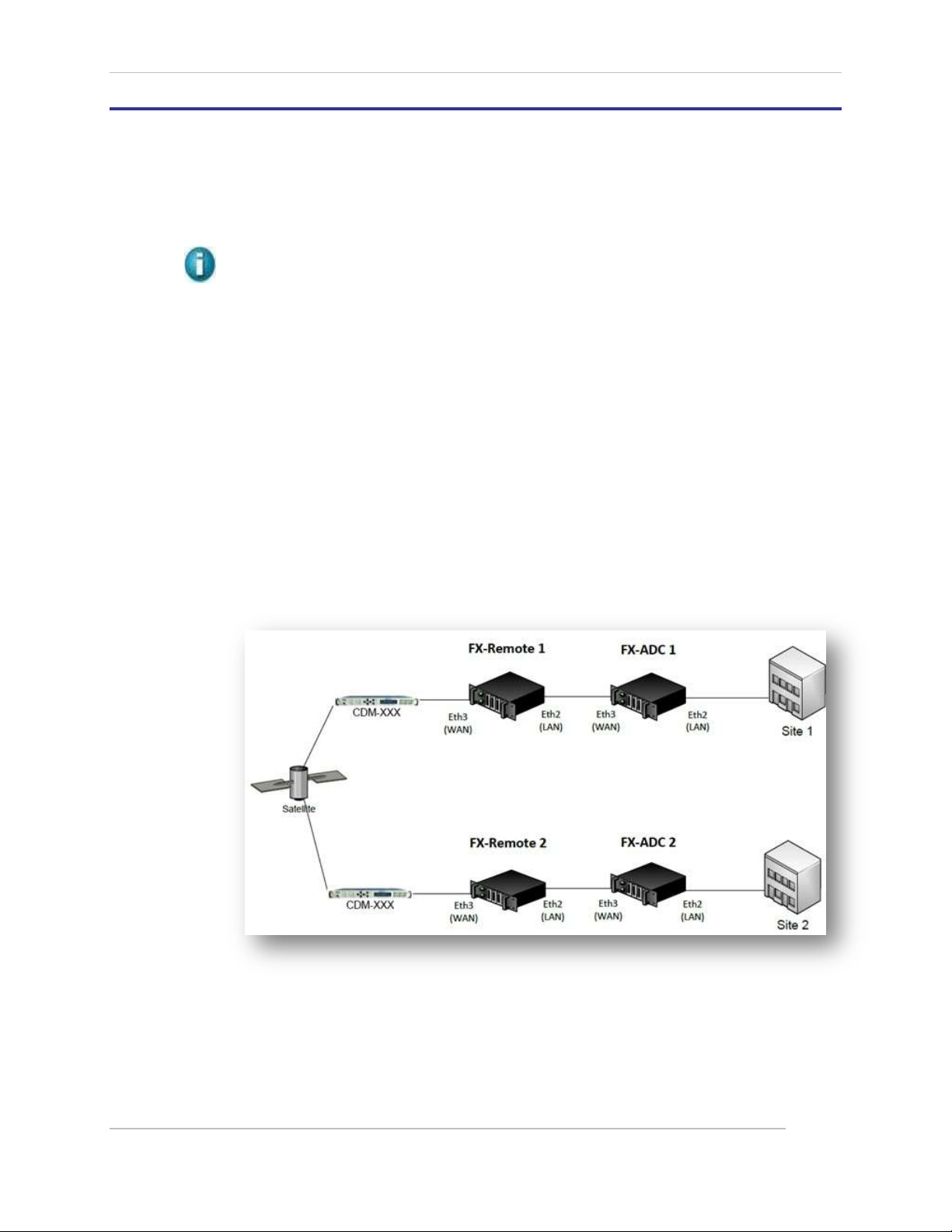
Comtech EF Data / Stampede
1.7 Mesh Networking with the FX Series
1.7.1 Theory of Operation
In addition to the single sided and the two sided client/server or Hub/Remote star network,
we’ve now introduced a full mesh network. We accelerate traffic from the FX Series Remote to
the FX Series ADC, with both appliances at each site.
NOTE: The FX Series Mesh can utilize the FX1005 appliances in a dual rack installation.
The FX Series Remote accelerates traffic by intercepting user requests and forwarding them to the FX
Series ADC. The FX Series ADC applies deflate compression, image transformation, static and dynamic
content caching.
The FX Series Remote applies static content caching, dynamic content caching, deflate compression,
Dynamic Data De-duplication, persistent connections, connection multiplexing, client side connection
termination, and TurboStreaming. To the client, the FX Series Remote appears to be the back-end
server.
1.7.2 Mesh Capability with two FX Series appliances at each node
All optimizations are handled – Remote to ADC
Traffic shaping, is done with the FX Remote, not the FX ADC
The first ADC picks up the traffic and will accelerate/optimize it.
The configurations for each appliance are done separately and have a cable connected
between the Remote LAN port and the ADC WAN port as shown below.
Figure 1-2 FX Series Basic Mesh Connectivity Diagram
FX Series Administration Guide - Version 6.1.1 35
Chapter: Overview - FX Series
Section: Mesh Networking with the FX Series MN-FXSERIESADM6 Rev 5
Page 36
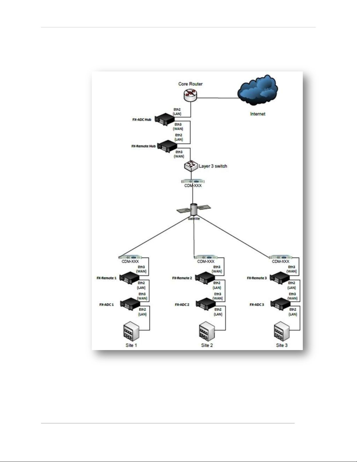
Comtech EF Data / Stampede
Hub/Spoke with meshing between FX Remotes, with the FX ADC hub available for web
browsing and other applications.
Figure 1-3 FX Series Hub Spoke Mesh Connectivity Diagram
FX Series Administration Guide - Version 6.1.1 36
Chapter: Overview - FX Series
Section: Mesh Networking with the FX Series MN-FXSERIESADM6 Rev 5
Page 37
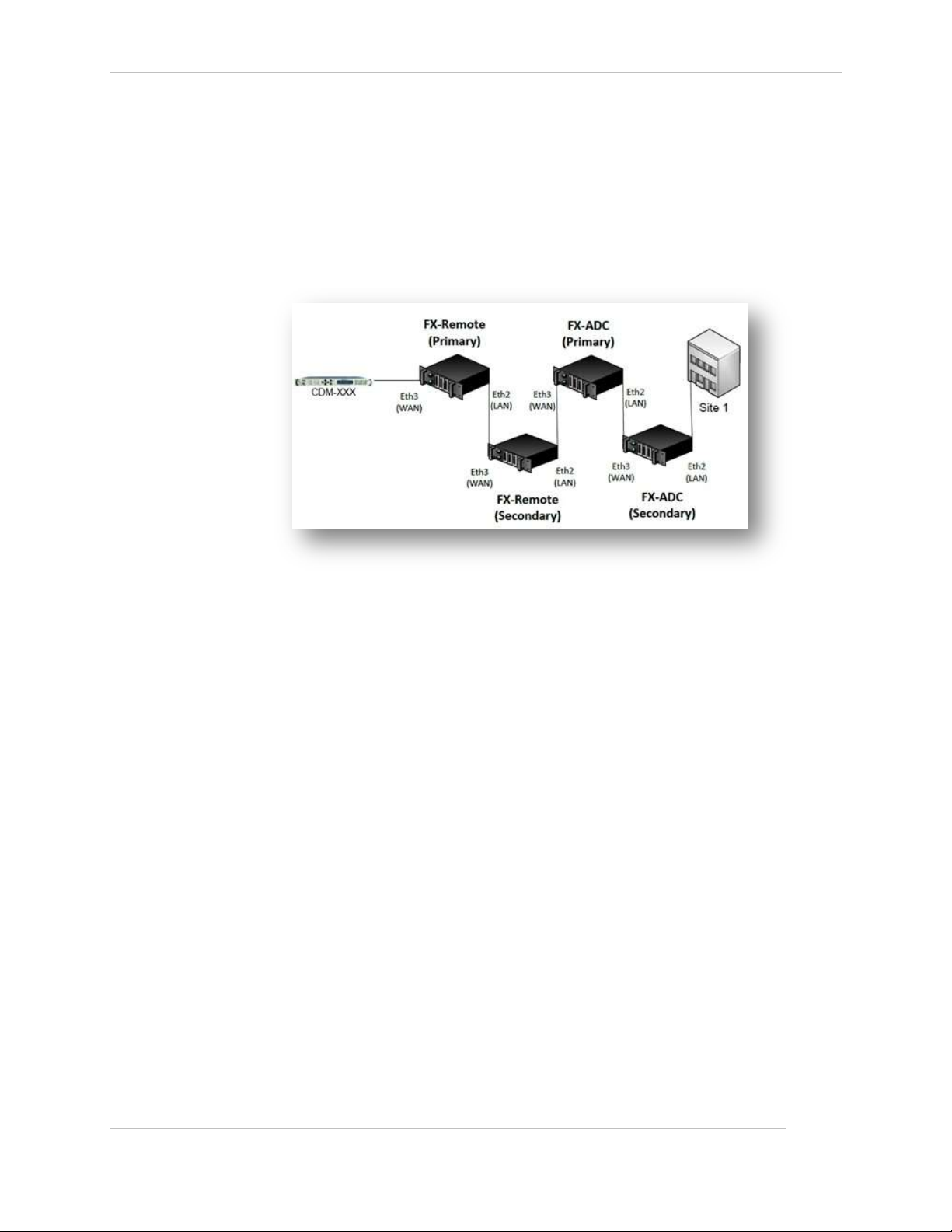
Comtech EF Data / Stampede
Mesh configuration with Redundancy
The Redundancy configuration could be set up at each site to provide total redundancy
The fail to wire capability is structured between the two like devices and between the
Remotes and the ADC as shown below.
The appliances are connected in series as shown below.
See the mesh deployment installation pattern for details.
.
Figure 1-4 FX Series Mesh with Redundancy Connectivity Diagram
FX Series Administration Guide - Version 6.1.1 37
Chapter: Overview - FX Series
Section: Mesh Networking with the FX Series MN-FXSERIESADM6 Rev 5
Page 38

Comtech EF Data / Stampede
FX-1005 ADC
FX-4010-ADC
Max Accelerated Sessions
3,000
30,000
Data Rate Options Mbps
1, 2, 4, 6, 10, 15
10, 15, 25, 45, 70, 155, 310
Load Balancing via WCCP
Connection Management
Advanced Traffic Shaping with ACM (d)
Source IP Preservation
Optimize VLAN Tagged Data
GZIP Compression (b)
Image Reduction (c)
Content Caching
Static Caching
Redundancy - In-Path and Routed Modes
FX-1005
REM/ADC
FX-1010 REM
FX-4010 REM/ADC
Max Accelerated Sessions (a)
6,000 (a)
6,000
30,000 (a)
Data Rate Options Mbps
1, 2, 4, 6, 10, 15
2, 4, 6, 10, 15, 25
10, 15, 25, 45, 70, 155, 310,
700 (f)
Header Compression Rate (PPS) (e)
35,000
700,000
Load Balancing via WCCP
Connection Management
Traffic Shaping with ACM (d)
IP Source Preservation
Optimize VLAN Tagged Data
Multicator
Content Reduction
Bi-directional Compression
Image Reduction (c)
Dynamic Data De-duplication
Content Caching
Static Caching
Cache Differencing
TCP Optimization
Multiplexing Data Streams
Auto Updates to the Remotes
1.8 FX Series Appliances Data Sheet
Deploy the Stampede FX Series (ADC) as a single-sided solution to optimize traffic from your outbound channel.
For a two-sided solution, add the FX Series Remote (REM) appliance and achieve the ultimate in application
acceleration and WAN optimization.
1.8.1 Single Sided with the Application Delivery Controller (ADC)
1.8.2 Two Sided with the ADC and the Remote
NOTES: (a) (b) (c) (d) (e) (f) See DATA SHEET Notes on next page
FX Series Administration Guide - Version 6.1.1 38
Chapter: Overview - FX Series
Section: FX Series Appliances Data Sheet MN-FXSERIESADM6 Rev 5
Figure 1-5 FX Series Appliances Data Sheet
Page 39
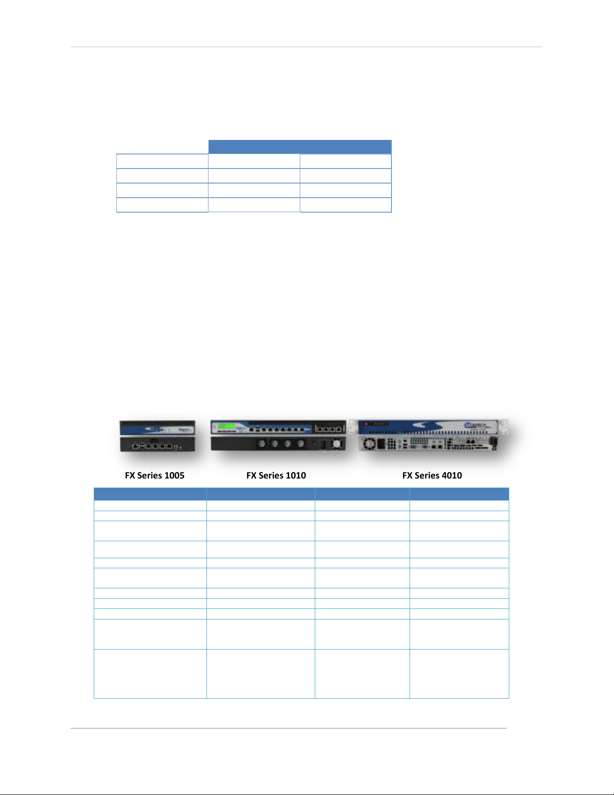
Comtech EF Data / Stampede
FX-4010-ADC
FX-1005-ADC
IMAGE SIZE
IMAGES PER SECOND
IMAGES PER SECOND
10 KB
1800
80
50KB
1000
35
500KB
100
35
Model
FX-1005
FX-1010
FX-4010
Form Factor
1RU
1RU
1RU
Weight
2.6 lbs (1.2kg)
13.3 lbs (6.0 kg)
15 lbs (6.8 kg)
Dimensions
(h x w x d)
1.7” x 8.5” x 7.4”
(43 x 215 x 188 mm)
1.7” x 17.0” x 15.6”
(44 x 431 x 395 mm)
1.7” x 16.8” x 14.0”
(43 x 427 x 356 mm)
Memory
4 GB
4 GB
16 GB
Storage
(1) 160 GB SATA
(1) 160 GB SATA
(1) 1 TB SATA III
Network Interface (GE)
Ports/Fail-to-Wire Pairs
4/1
11/0
4/1
Serial Ports 1 1
1
USB Interface Ports
2 2 2
Rack Mount Kits
1 or 2 units in 1RU
Power Supply – UL Approved,
FCC Compliant
Requires a 60 W/12V power
adapter with lock
200 W ATX power supply
unit with input range of
90~264V@ 47-63 Hz
Single Power
(200 W)
Auto (100V-240V)
Environment
Operating temp
0 - 40°C,
Storage temp
-20 - 60°C,
Humidity 5 - 90%
Operating temp
0 - 40°C,
Storage temp
-20 - 60°C,
Humidity 5 - 90%
Operating temp
10 - 35°C,
Storage temp
-40 - 70°C,
Humidity 8 - 90%
Data Sheet Notes:
(a) When used as an ADC, the FX-1005 will handle 3000 concurrent sessions.
(b) Maximum accelerated WAN rates are a function of compressibility. If all content is being GZIP compressed
with a ratio of greater than 4:1, the maximum WAN rate may not be accelerated.
(c) The number of images handled per second is a function of image size.
(d) Available as either a stand-alone feature or part of the WAN optimization product. As a stand-alone feature,
the maximum data rate is 700 Mbps, when purchased with the WAN optimization; the data rate is limited to
the WAN optimization rate.
(e) Packets per second (PPS) is 50% outbound and 50% inbound. Header compression is currently only available
in point-to-point configurations and is not currently supported in the FX-1010. Header Compression is
currently available as either a standalone feature added to the base configuration or part of the WAN
Optimization product. When purchased without the WAN Optimization feature the maximum rate is 700KBps.
When included with WAN Optimization, the data rate is limited to the WAN Optimization rate.
(f) Header Compression only.
Configuration Models
Base Configuration with QOS only as an option with no WAN Optimization.
Option 1 Add Header Compression (rates up to700KBps) with no WAN Optimization.
Option 2 Wan Optimization including Header Compression with rates as shown in the tables.
1.8.3 FX Series Hardware Specification
FX Series 1005 FX Series 1010 FX Series 4010
FX Series Administration Guide - Version 6.1.1 39
Chapter: Overview - FX Series
Section: FX Series Appliances Data Sheet MN-FXSERIESADM6 Rev 5
Figure 1-6 FX Series Hardware Specifications
Page 40
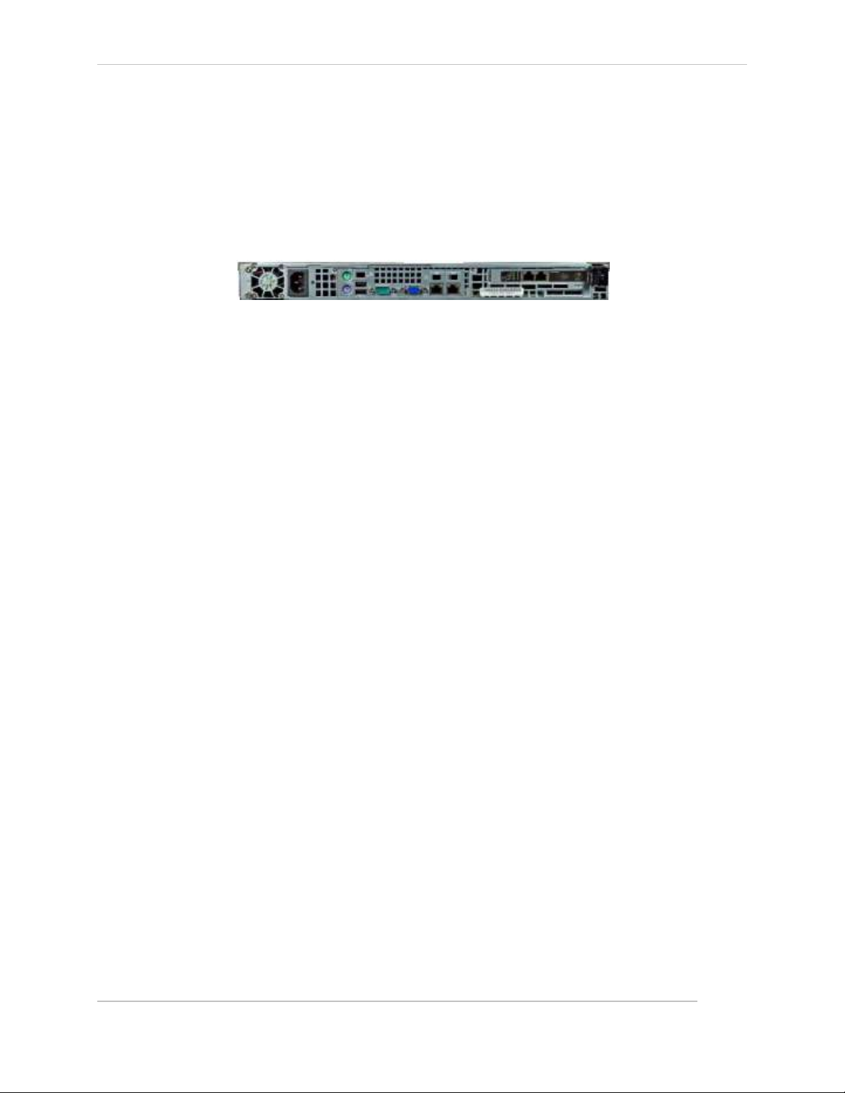
Comtech EF Data / Stampede
1.8.4 FX-4010 Physical Description
Back Panels
Using suitable RJ-45 cable, you can connect FX Series FX-4010 System to a computer, or to any other
piece of equipment that has an Ethernet connection; for example, a hub or a switch. Moreover,
LAN3-LAN4 is configured as LAN Bypass when failure events occur.
1) (MGT) Management
2) (AUX) Auxiliary
3) (LAN)
4) (WAN)
Figure 1-7 FX Series FX-4010 Back Panel
From left to right
1. Power-In Socket
2. Inputs for mouse and keyboard
3. (2) USB 2.0 Ports
4. Serial Port
5. VGA Port
6. MGT Port Eth(0)
7. AUX Port Eth(1)
8. LAN Eth(2)
9. WAN Eth(3)
FX Series Administration Guide - Version 6.1.1 40
Chapter: Overview - FX Series
Section: FX Series Appliances Data Sheet MN-FXSERIESADM6 Rev 5
Page 41
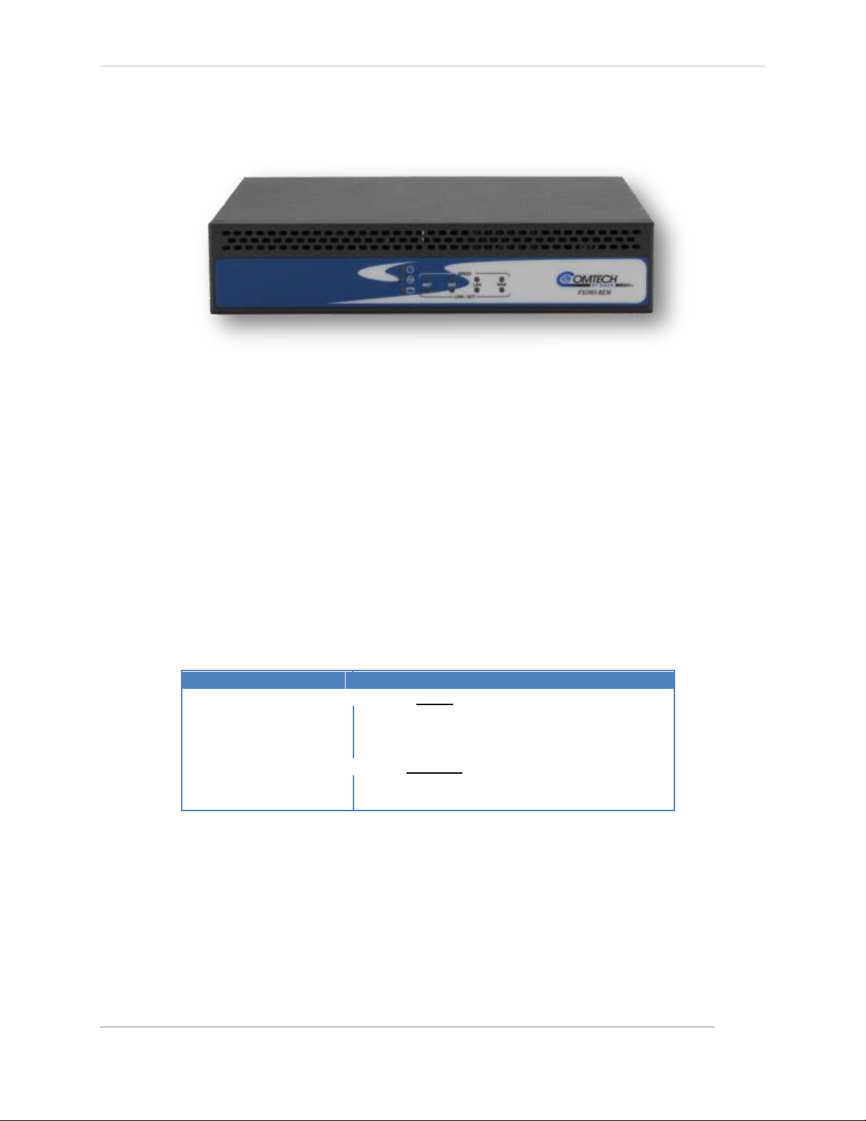
Comtech EF Data / Stampede
LED Indicator
Interpretation
SPEED
Amber
The connection speed is 1000Mbps
Green
The connection speed is 100Mbps
Off
The connection speed is 10Mbps.
LINK/ACT
On/Flashing (Yellow)
The port is linking.
Off
The port is not linking.
1.8.5 FX-1005 Physical Description
Front Panel
Figure 1-8 FX Series FX-1005 Front Panel
Power/Status/HDD LED (left vertical icons)
Power (Green): If the LED is on it indicates the system is powered on. If it is off, it indicates the
system is powered off.
Status (Green/Amber): If the LED is Green, it indicates that the system’s operational state is
normal.
If it is Amber, it indicates that the system is malfunctioning.
HDD (Yellow): If the LED blinks, it indicates data access activities; otherwise, it remains off.
LED indicators for Network Ports:
1 Management Port 2 Auxiliary Port 3 LAN Port 4 WAN Port
FX Series Administration Guide - Version 6.1.1 41
Chapter: Overview - FX Series
Section: FX Series Appliances Data Sheet MN-FXSERIESADM6 Rev 5
Page 42

Comtech EF Data / Stampede
Rear Panel
Reset Switch
Use a pointed object to press the reset button to reboot the system without turning off the power.
Console Port
By using suitable rollover cable (also known as Cisco console cable), you can connect to a computer
terminal for diagnostic or configuration purpose
Figure 1-9 FX Series FX-1005 Rear Panel
Two USB 2.0 Ports
It connects to any USB devices, for example, a flash drive
4 Gigabit LAN ports
Using suitable RJ-45 cable, you can connect FX Series 1005 System to a computer, or to any other
piece of equipment that has an Ethernet connection; for example, a hub or a switch. Moreover,
LAN3-LAN4 are configured as LAN Bypass when failure events occur.
1) (MGT) Management
2) (AUX) Auxiliary
3) (LAN)
4) (WAN)
DC-in 12V Jack
The system requires a 60W/12V power adapter with lock.
Power-on Switch
It is a switch to turn on or off the power.
Summary of Specifications
Network Interface /Fail to Wire
Power Supply – UL Approved
(4) GbE ports, (1) pair bypass
200 W (Auto 100V – 200V)
System Subscription 1 Year of hardware/software support, maintenance and updates
FX Series Administration Guide - Version 6.1.1 42
Chapter: Overview - FX Series
Section: FX Series Appliances Data Sheet MN-FXSERIESADM6 Rev 5
Page 43

Comtech EF Data / Stampede
Figure 1-10 FX Series FX-1010 Front Panel
1.8.6 FX-1010 Physical Description
Front Panel
F1 Power/Status/HDD LED
Power:
If the LED is on it indicates that the system is powered on. If it is off, it indicates that the system is
powered off.
Status:
If the LED is green, it indicates that the system’s operational state is normal. If it is red, it indicates
that the system is malfunctioning.
HDD:
If the LED is on, it indicates that the system’s storage is functional. If the LED blinks, it indicates
data access activities. If it is off, it indicates that there is no hard disk present or functional.
F2 System Panel: LCD System Panel
The LCD System Panel is programmed to display WOC on the first line and “Active” on the second.
F3 Reset Switch:
The reset switch can be used to reboot the system without turning off the power.
F4 Console Port:
By using suitable rollover cable or RJ-45 to DB-9 Female (Cisco console cable), you can connect to
a computer terminal for diagnostic or configuration purpose. Default terminal Configuration
Parameters: 115200 baud, 8 data bits, no parity, 1 stop bit, no flow control.
F5 Two USB 2.0 Ports:
It connects to any USB devices, for example, a flash drive.
F6 Management Port and Auxiliary Ports:
The Management Port is a Fast Ethernet port that can be connected for configuration or
troubleshooting purpose. It conforms to the IPMI (Intelligent Platform Management Interface)
and can be implemented on this port through the Open Platform Management Architecture
(OPMA) interface.
F7 5 Gigabit LAN ports (Ports 1-5)
Right LED:
If the LED is orange, it indicates that the connection speed is 1000Mbps. If the LED is green, it
indicates that the connection speed is 100Mbps. And if it is off, it indicates that the speed is
10Mbps.
FX Series Administration Guide - Version 6.1.1 43
Chapter: Overview - FX Series
Section: FX Series Appliances Data Sheet MN-FXSERIESADM6 Rev 5
Page 44

Comtech EF Data / Stampede
Left LED:
If the LED is on, it indicates that the port is linked. If it blinks, it indicates there is traffic.
Using suitable RJ-45 cable, you can connect FX-1010 system to a computer, or to any other piece
of equipment that has an Ethernet connection; for example, a hub or a switch.
F8 4 Gigabit LAN ports (Ports 6, 7, 8, WAN) Expansion Module
This expansion of the LAN switch adds an additional 4 Ethernet ports.
Rear Panel
4 System CPU Fans
Power-on Switch
Figure 1-11 FX Series FX-1010 Rear Panel
AC Power-in socket -
200W ATX power supply unit with input range of 90~264V@47-63Hz.
Power Supply Fan
Summary of Specifications
Network Interface /Fail to Wire (4) 10/100/1000, (1) 10/100/1000 bypass pair
Power Supply – UL Approved 200 W (Auto 100V – 200V)
System Subscription - 1 Year of hardware/software support, maintenance and updates
Rack Mounting
Rack mounting hardware is included with FX-1010 appliance
FX Series Administration Guide - Version 6.1.1 44
Chapter: Overview - FX Series
Section: FX Series Appliances Data Sheet MN-FXSERIESADM6 Rev 5
Page 45

Comtech EF Data / Stampede
1.8.7 Hardware Mounting Options for FX Series FX-1005
Tabletop Mounting (Standard)
To mount the FX-1005 on the table, use the rubber feet in the tabletop mounting pack.
Follow the following procedures as a guideline: (may be pre-attached)
1. Place the rubber feet on the mounting spots at the bottom of the FX-1005 .
2. Place the FX-1005 on the table using the rubber feet.
Double Unit Rack Mount (Optional Accessory)
To mount two FX-1005 systems onto the rack, use the mounting kit with the screw pack.
Follow the following procedures as a guideline:
1. Attaching two screws having a washer
under the head to the inner side of the
system’s chassis.
2. Align the screws of one system with
the mounting slots of the other system
and mount the two systems side by side
by clipping them together
3. Make sure that the attachment between
the two systems is secure and the
mounting screws are locked in place.
4. Use the screws provided to fix the short
ear-bracket to the left and right sides of
the system as shown in the picture.
5. Use the mounting hardware included to
attach and secure the bracket to the rack.
Installing the ear-bracket to the rear side as an alternative rack mounting
NOTE: The short-ear bracket could also be mounted at the rear side of the system. Thus, the rear panel of
the system could be mounted in the front of the rack mounting equipment.
Single Unit Rack Mount (Optional Accessory)
NOTE: Place the power adaptor in the bracket first before installing the adaptor holder.
To mount the FX-1005 onto the rack, use the
mounting kit with the screw pack.
Follow these procedures as a guideline:
1. Attach the adaptor mounting bracket
to the system by fastening 5 screws
2. Place the adaptor in the adaptor
mounting bracket.
3. Make sure that the power adaptor’s
AC socket is not blocked. Align the AC
socket with the holes on the mounting
bracket.
4. You could use the adaptor holder to
hold your adaptor to prevent it from
sliding back and forth.
5. Use 3 screws provided to fix the bracket to the left and right side of the system.
6. Use the mounting hardware included to attach and secure the bracket to the rack.
FX Series Administration Guide - Version 6.1.1 45
Chapter: Overview - FX Series
Section: FX Series Appliances Data Sheet MN-FXSERIESADM6 Rev 5
Page 46

Comtech EF Data / Stampede
2 Pre-Installation Information
2.1.1 Unpacking
Inspect shipping containers for damage. If shipping containers are damaged, keep them until the
contents of the shipment have been carefully inspected and checked for normal operation.
The FX Series appliance is packaged in pre-formed, reusable, cardboard cartons containing foam spacing
for maximum shipping protection.
Unpack the appliance as follows:
Step Procedure
1 Remove the appliance, and the power cord and cables from the carton.
2 Save the packing material for storage or reshipment purposes.
3 Inspect the appliance for any possible damage incurred during shipment.
4 Check the equipment and accessories against the packing list to ensure the shipment is
correct.
Parts List
Acceleration Appliance
Quick Start Guide
1 - Power Cord
2 - Cat5e 7ft UTP Snagless Cable
1 - Cat5e Crossover Red 7ft UTP Snagless Cable
1 – Null Modem 6ft Cable
2.1.2 User Interfaces
The FX Series supports a basic menu-driven interface, which is accessible using the console port (eth0) or
a web-based graphical user interface (GUI). Initial network configurations are managed thru the console
connection, and the optimization and general operations functions are managed via the GUI. There are
three alternate methods to connect to the FX Series Appliance
1. Attach a Monitor, keyboard and mouse to device.
2. Connect the supplied serial cable with a setting of (19200,N,8,1)
3. Attach a cross-over cable to the eth1 interface which has a static IP address of 169.254.55.55
(See FX Series Console Management Functions in Appendix)
To connect to the Web GUI using a PC with a
Browser access:
http://yourFxHostname:10000 or
http://IP:10000
The default USERID and PASSWORD are
“comtech” and “comtech” for both the console
and the GUI.
FX Series Administration Guide - Version 6.1.1 46
Chapter: Pre-Installation Information
Section: FX Series Appliances Data Sheet MN-FXSERIESADM6 Rev 5
Page 47

Comtech EF Data / Stampede
2.1.3 Documentation
Before you try to install the FX Series appliance on your network, please review the documentation in the
Installation Patterns Guide.
Current Documentation for this appliance can be found on these locations.
On the Comtech EF Data web site:
http://www.comtechefdata.com/stampedeDocs.asp
Or
www.comtechefdata.com
Under Support Information, Click on Manuals
Under RAN & WAN Optimization, click on Stampede FX Series
On the Appliance:
To connect to the GUI, use any PC with a Web Browser to access:
• Attach a cross-over cable to the eth1 interface and connect to the browser interface at http://
169.254.55.55:10000
• Login using the USERID and password of “comtech” and “comtech”
• Using the web GUI
• Click on the FX Series Appliance Administration link for the Main Index
• Click on “Documentation” from the Main Index
To view a document, click on the link in the left column of each row of the table. You can right click on
the link and choose “Save target as” to save a copy of the “.pdf” file to your desktop.
2.2 Configure Appliance Management Address – All Installation Patterns
Log into the appliance via console or SSH session using the username: comtech and password: comtech
1 Select option 1 “Configure appliance”
2 Select option 1 “Configure network settings”
3 Select option 4 “Configure TCP/IP for eth0 Ethernet Port”
4 Select option 1 “Configure DHCP”
a. Enter no and press Enter key (disable DHCP for this interface)
5 Select option 2 “Configure IP Address”
a. Enter the IP address of the appliance and press enter
6 Select option 3 “Configure Netmask”
a. Enter the subnet mask and press the Enter key
7 Select option 0 “Return to previous menu”
8 Select option 3 “Configure Default Gateway”
a. Enter the default gateway IP address and press the Enter key
Verify network connectivity by doing a ping of the appliance address from an external device.
Depending on the environment, there are several network installation patterns that can be used.
• Bridged (“In-Path”)
• Routed
• WCCP
• Mesh
These are documented in the FX Series Network Installation Patterns section of the Administration Guide.
FX Series Administration Guide - Version 6.1.1 47
Chapter: Pre-Installation Information
Section: Configure Appliance Management Address – All Installation Patterns MN-FXSERIESADM6 Rev 5
Page 48
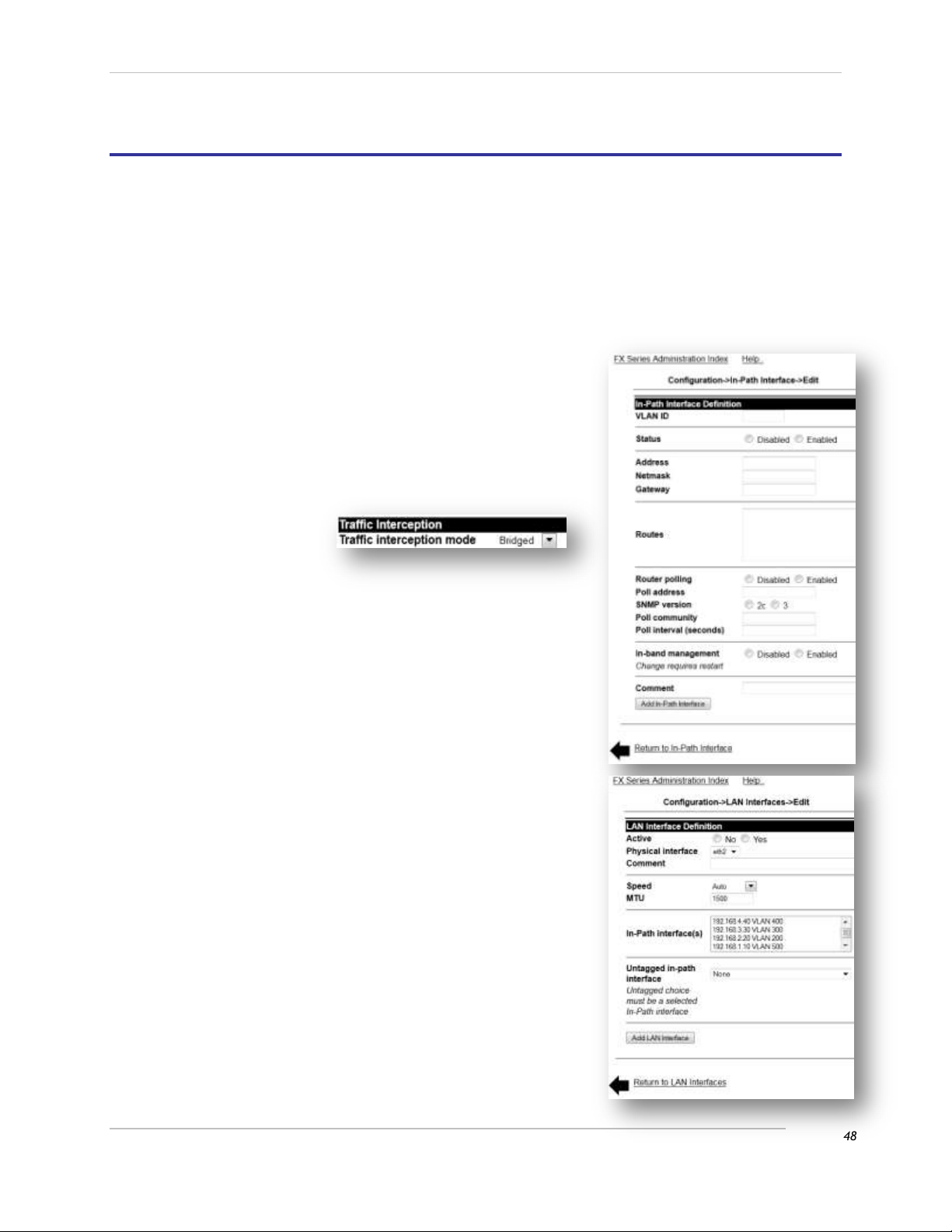
Comtech EF Data / Stampede
3 FX Series Network Installation Patterns
3.1 FX Series Installation Pattern (In-Path Bridged)
3.1.1 Cable the Appliance
The eth2 (LAN) and eth3 (WAN) ports both need to be connected to a switch or router in which:
1. The eth2 (LAN) port is on the link closest to the:
a. Backend servers if the appliance is an FX-ADC.
b. Clients if the appliance is a FX-Remote.
2. The eth3 (WAN) port is on the link closest to the satellite modem.
3.1.2 Configure the Appliance
Login to the appliance through the browser interface at:
http://{IP_address_of_the_appliance}:10000
1. Enter the default user name “comtech” and the default
password “comtech”.
a. Click Login.
2. Click Configuration -> General Settings
a. Change “Traffic interception mode” to “Bridged”.
b. Click Save.
3. Click In-Path Interfaces
a. Click the Add button to add a new in-path
interface.
Enter the VLAN ID of 0. If no VLAN tagging is to
be used. Use the VLAN ID of the VLAN if traffic
is to be VLAN tagged
Enter the IP Address.
Enter the Netmask.
Enter the Gateway.
Enter any static routes needed in the “Routes”
field.
b. Click “Add In-Path Interface”.
c. Click the “Return to Configuration” link.
4. Click on LAN Interfaces.
a. Click on the “Add” button to add a new LAN
interface.
Select “eth2” in the “Physical interface”
selection box.
In the “In-Path Interface(s)” selection box,
click the IP address of the in-path interface
*from above*.
In the “Untagged in-path interface” selection
box, select the IP address of the in-path
interface *from above*. Select “None” if the
VLAN tag is to be propagated across the WAN.
b. Click “Add LAN Interface”.
c. Click the “FX Series Administration Index” link at
the top of the page.
5. Click “Status”, then click “Real-Time Monitor”, then click
“Restart Service”.
FX Series Administration Guide - Version 6.1.1 48
Chapter: FX Series Network Installation Patterns
Section: FX Series Installation Pattern (In-Path Bridged) MN-FXSERIESADM6 Rev 5
Page 49
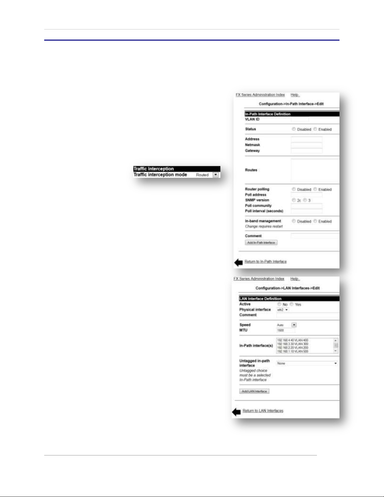
Comtech EF Data / Stampede
3.2 FX Series Installation Pattern (Routed)
3.2.1 Cable the Appliance
Connect the eth3 (WAN) port to a switch or a router.
3.2.2 Configure the Appliance
Login to the appliance through the browser interface at:
http://{IP_address_of_the_appliance}:10000
1. Enter the default user name “comtech” and the
default password “comtech”.
a. Click Login.
2. Click Configuration -> General Settings
a. Change “Traffic interception mode” to
“Routed”
b. Click Save
3. Click In-Path Interfaces
a. Click the Add button to add a new in-path
interface.
Enter the VLAN ID of 0, if no VLAN is to be
tagged. Use the VLAN ID of the VLAN if
traffic is to be VLAN tagged.
Enter the IP Address.
Enter the Netmask
Enter the Gateway
Enter any static routes needed in the
“Routes” field.
b. Click “Add In-Path Interface”
c. Click the “Return to Configuration” link
4. Click on LAN Interfaces.
a. Click on the “Add” button to add a new LAN
interface.
Select “eth3” in the “Physical interface”
selection box.
In the “In-Path Interface(s)” selection
box, click the IP address of the in-path
interface *see above*.
In the “Untagged in-path interface”
selection box, select the IP address of the
in-path interface *see above*. Select
“none” if the VLAN tag is to be
propagated across the WAN.
b. Click “Add LAN Interface”.
c. Click the “FX Series Administration Index” link
at the top of the page.
5. Click “Status”, then click “Real-Time Monitor”, then click “Restart Service”.
FX Series Administration Guide - Version 6.1.1 49
Chapter: FX Series Network Installation Patterns
Section: FX Series Installation Pattern (Routed) MN-FXSERIESADM6 Rev 5
Page 50
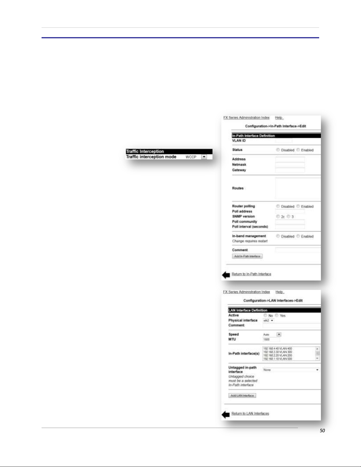
Comtech EF Data / Stampede
3.3 FX Series Installation Pattern (WCCP)
3.3.1 Cable the Appliance
Connect the eth2 (LAN) port to a switch or a router.
3.3.2 Configure the Appliance
Login to the appliance through the browser interface at: http://{IP_address_of_the_appliance}:10000
6. Enter the default user name “comtech” and the default
password “comtech”.
a. Click Login.
7. Click Configuration -> General Settings
c. Change “Traffic interception mode” to “WCCP”
d. Click Save
8. Click In-Path Interfaces
a. Click the Add button to add a new in-path
interface.
Enter the VLAN ID of 0.
Enter the IP Address.
Enter the Netmask
Enter the Gateway
Enter any static routes needed in the
“Routes” field.
b. Click “Add In-Path Interface”
c. Click the “Return to Configuration” link
9. Click on LAN Interfaces.
a. Click on the “Add” button to add a new LAN
interface.
Select “eth3” in the “Physical interface”
selection box.
In the “In-Path Interface(s)” selection box,
click the IP address of the in-path interface
*see above*.
In the “Untagged in-path interface”
selection box, select the IP address of the
in-path interface *see above*.
b. Click “Add LAN Interface”.
c. Click the “FX Series Administration Index” link
at the top of the page.
d. Click “Status”, then click “Real-Time Monitor”,
then click “Restart Service”.
e. Click the “FX Series Administration Index” link
at the top of the page.
f. Click “Configuration”
10. Click “WCCP”
FX Series Administration Guide - Version 6.1.1 50
Chapter: FX Series Network Installation Patterns
Section: FX Series Installation Pattern (WCCP) MN-FXSERIESADM6 Rev 5
Page 51
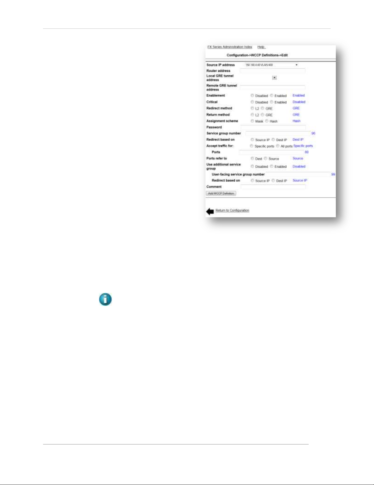
Comtech EF Data / Stampede
a. Click “Add WCCP Definition”
b. Select the IP address of the interface
that will send the WCCP messages to
the router in the “Source IP address”
selection box.
c. Enter the routers IP address in the
“Router address” field.
d. Select the local interface that will
receive the GRE traffic if using GRE
redirection. If using L2 redirection
leave blank.
e. If using GRE redirection enter the
router identifier of the router in the
“Remote GRE tunnel address” field. If
using L2 redirection leave blank.
f. Use default value for “Enablement”.
g. Use default value for “Critical”.
h. Select Redirection method.
i. Select the same value used for
Redirection method.
j. For L2 use Mask Assignment scheme. For GRE use Hash Assignment scheme. * This may
differ on highest end Cisco equipment.
k. Leave the password field blank, unless one was configured for WCCP on the Cisco device.
l. If using “web-cache” WCCP redirection (no source IP address preservation) enter 0 in the
“Service group number” field. If using source IP address preservation use the default value.
m. Use the default values for “Redirect based on”, Accept traffic for”, and “Ports”.
n. If using source IP address preservation select “Enabled” for “Use additional service group”. If
using “web-cache” default this value.
o. Click “Add WCCP Definition”
11. Click “Status”, then click “Real-Time Monitor”, then click “Restart Service”.
NOTE: See Section 4.9 below for details and difference.
FX Series Administration Guide - Version 6.1.1 51
Chapter: FX Series Network Installation Patterns
Section: FX Series Installation Pattern (WCCP) MN-FXSERIESADM6 Rev 5
Page 52
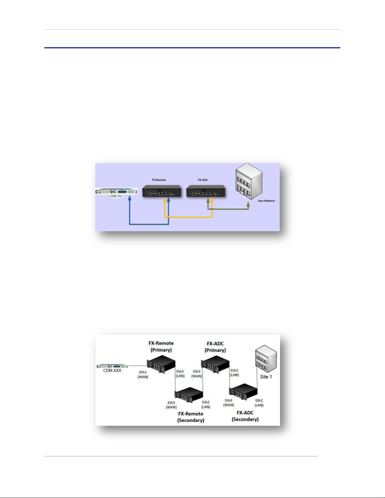
Comtech EF Data / Stampede
3.4 Installation of Two FX Series Appliances in a Mesh Configuration
This configuration consists of two FX Series appliances, one configured as a FX Series ADC and the second
appliance configured as a FX Remote.
NOTE: Two FX1005 appliances can be installed in a rack using the Double Unit Rack Mount (See
1.8.7 above)
A short cable is provided for the connection from the Remote’s LAN port to the ADC’s WAN port (the
yellow connection in the figure below:
(See picture of rear panel in section 1.8.5 above)
1. Connect the Eth3 (WAN) port of FX Remote to the satellite connection. [Blue]
2. Connect the Eth2 (LAN) port of the FX-Remote to the Eth3 (WAN) port of the FX-ADC. [Yellow]
3. Connect the Eth2 (LAN) port of the FX-ADC to the user network. [Green]
Figure 3-1 FX Series Mesh Connection Diagram
3.4.1 Configure the appliances
Configure as noted in Sections 2.2 and 3 above
3.4.2 Mesh installation with Redundancy capability
This scenario consists of two sets of appliances at the site. The configuration for each appliance is done
separately to backup FX Series Appliances with fail to wire configuration. The configuration setups are
similar as described in Section 4.8 below and is shown diagramed here.
FX Series Administration Guide - Version 6.1.1 52
Chapter: FX Series Network Installation Patterns
Section: Installation of Two FX Series Appliances in a Mesh Configuration MN-FXSERIESADM6 Rev 5
Page 53

Comtech EF Data / Stampede
4 FX Series Network Settings
Figure 4-1 FX Series Standard Configuration Screen
4.1 Standard Network Configuration Overview
The following network screens provide common interfaces for the FX Series appliances.
Application Policies
Customize the optimization techniques that will apply to your enterprise applications.
(See the Optimization Acceleration Settings in Section 8 below).
FX Series Basic Network Interfaces
Define network settings for management and auxiliary interfaces.
FX Series General Settings
The General Settings control the method of traffic interception and WCCP. In addition, this
section includes settings to configure basic HTTP settings, system time and software updates of
FX-Remotes. See Specific Sections below.
FX Series ADC Specific Settings Section
FX Series Remote Specific Settings Section
FX Series Redundancy
Configure a Redundancy cluster that can share a common configuration.
FX Series Host Settings
Configure the host name and DNS settings to facilitate management and time synchronization.
FX Series In-Path Interfaces
For FX Series ADC see: Configure network settings for the interfaces for user data.
For FX Series Remote In-Path Interfaces see: FX Series Remote Specific Settings Section.
FX Series LAN Interfaces
Set speed, MTU and VLAN options of the physical LAN interfaces. .
FX Series Multicator Settings
Configure reliable multicast fan-out settings.
FX Series Administration Guide - Version 6.1.1 53
Chapter: FX Series Network Settings
Section: Standard Network Configuration Overview MN-FXSERIESADM6 Rev 5
Page 54

Comtech EF Data / Stampede
Port Definitions
Configure a list of port definitions see: FX Series ADC Specific Settings Section.
FX Series Quality of Service Settings
Define ACM settings and configure QoS.
WCCP Settings
The Web Cache Communication Protocol (WCCP) is a Cisco-developed content-routing technology which
allows you to integrate cache engines into your network infrastructure.
NOTE: The screens that have specific functionality for the FX Series ADCs or the FX Series Remotes
can be found in these sections: FX Series ADC Specific Settings Section or the FX Series Remote
Specific Settings Section.
FX Series Administration Guide - Version 6.1.1 54
Chapter: FX Series Network Settings
Section: Standard Network Configuration Overview MN-FXSERIESADM6 Rev 5
Page 55
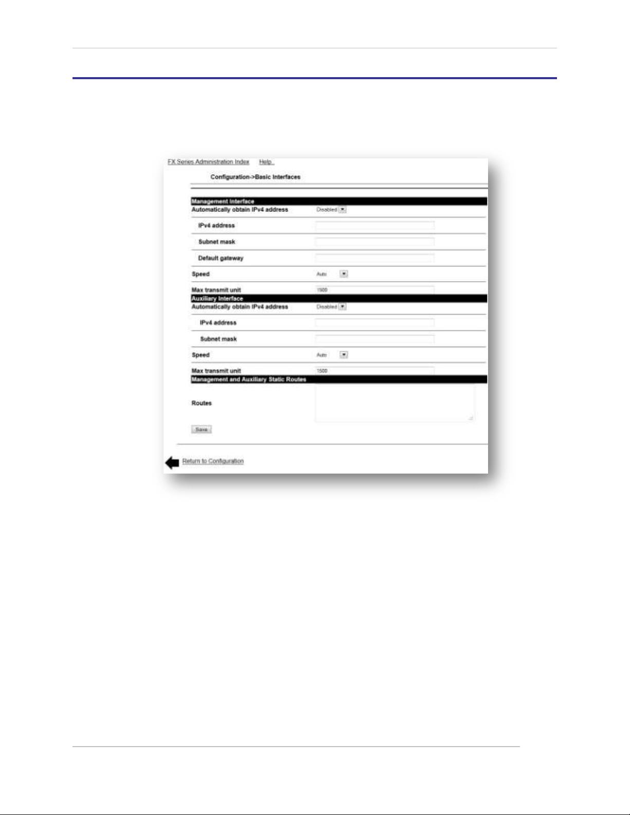
Comtech EF Data / Stampede
4.2 Basic Network Interfaces
The FX Series reserves two ports, management and auxiliary, for management traffic. This traffic is
isolated from the ports in which accelerated traffic flows. These interfaces are tied to a management
routing table which is not used for accelerated traffic.
Figure 4-2 FX Series Basic Network Interfaces Screen
4.2.1 Management Interface
The management interface corresponds to the “eth0” Ethernet port. Typically the management interface
is connected to a private network where system management tools such as ssh, the management web
GUI, and SNMP are utilized.
Automatically obtain IPv4 address:
If set then the FX appliance will use DHCP to obtain an IP address, subnet mask, and default gateway. The
factory default for the management interface is to use DHCP.
IPv4 Address:
This is the IP address of the management interface.
Subnet Mask:
This specifies the network that the management interface is on. The default value is
255.255.255.0.
FX Series Administration Guide - Version 6.1.1 55
Chapter: FX Series Network Settings
Section: Basic Network Interfaces MN-FXSERIESADM6 Rev 5
Page 56

Comtech EF Data / Stampede
Default Gateway:
This is the IP address of the gateway for which packets that are outside the bounds of the
management subnet will be directed. A default gateway address which is on the same subnet as
depicted by the “IPv4 address” and “Subnet mask” must be specified even if the gateway does
not exist.
Speed:
This presents a pull-down selector of speed/duplex combinations that will be set for this interface. The
default value is to automatically negotiate the speed and duplex.
Max Transmit Unit (MTU):
Specifies the max transmit unit. The default value is 1500. The range is 576 to 9000.
4.2.2 Auxiliary Interface
Automatically obtain IPv4 address:
If set, then the FX appliance will use DHCP to get an IP address, subnet mask, default gateway.
IPv4 address:
This is the IP address of the auxiliary interface. The factory default is 169.254.55.55.
Subnet mask:
This specifies the network that the auxiliary interface is on. The default value is 255.255.0.0.
Speed:
This presents a pull-down selector of speed/duplex combinations that will be set for this interface. The
default value is to automatically negotiate the speed and duplex.
Max Transmit Unit (MTU):
Specifies the max transmit unit. The default value is 1500. The range is 576 to 9000.
4.2.3 Management Static Routes
Routes:
Enter into the text area static routes which are used by the management interface. Each static
route must be entered on a separate line and must have exactly the following format:
Subnet “SubnetMask” “Gateway”
For example, to define a static route such that subnet 172.88.0.0/16 should be routed by
gateway 172.27.101.99 you would enter the following:
172.88.0.0 255.255.0.0 172.27.101.99
FX Series Administration Guide - Version 6.1.1 56
Chapter: FX Series Network Settings
Section: Basic Network Interfaces MN-FXSERIESADM6 Rev 5
Page 57

Comtech EF Data / Stampede
4.3 Host Settings
In most environments, configuring host names and DNS is not required for the FX to operate because for
most accelerated traffic, the IP address of the content server is resolved by the originating client before it
is processed by the FX. The host settings should be set to facilitate management and time
synchronization.
Figure 4-3 FX Series Host/DNS Settings Screen
4.3.1 Host Networking Settings
Host name:
This is the host name of the appliance. This must be a “short” name and must not contain any periods. A
fully qualified name is formulated by appending a ‘.’ followed by whatever is entered into the “Domain”
field.
Domain:
This is the DNS domain of the appliance.
DNS Servers:
Enter one or more IP addresses separated by commas.
FX Series Administration Guide - Version 6.1.1 57
Chapter: FX Series Network Settings
Section: Host Settings MN-FXSERIESADM6 Rev 5
Page 58

Comtech EF Data / Stampede
4.3.2 Host File Entries
Hosts:
If no DNS is available, this field allows you to map specific host names to an IP address. This may be
needed for active-passive redundant configurations. Each entry should be on a separate line. The format
of each line is:
“nn.nn.nn.nn FullyQualifiedHostName OptionalShortHostName”
Where nn.nn.nn.nn is the IpV4 address that you want to assign to FullyQualifiedHostName”.
DNS Server Configuration Guidelines:
In order for the fully qualified host name to be accurate within a domain, it is a best practice to set your
local DNS server to match the IP address of the FX appliance with the name “Host name” and “Domain”
fields on this page. Or you can set a “Host File Entry” with the IP address of the FX appliance with the fully
qualified name and the short name.
FX Series Administration Guide - Version 6.1.1 58
Chapter: FX Series Network Settings
Section: Host Settings MN-FXSERIESADM6 Rev 5
Page 59

Comtech EF Data / Stampede
4.4 In-Path Interface
These settings allow you to maintain in-path interfaces. A list of previously defined in-path interfaces are
displayed in the order in which they were defined. An existing entry may be chosen by clicking on the IP
Address. The user adds interfaces by clicking the “Add” button. Interfaces can be “enabled” or “disabled”
by checking box to the left of the IP address and clicking on the enable or disable button. Clicking on the
Interface “Name” will allow you to modify that Interface. Each of those actions will then lead to an In Path Interface screen.
Figure 4-4 FX Series In-Path Interfaces Definition Screen
4.4.1 In-Path Interface Definition
VLAN ID:
If this interface carries tagged VLAN traffic, then enter the VLAN ID number which is a value between 2
and 4094. Untagged traffic should have a value of 0. The default is 0.
Address:
This is the IPv4 address of this interface.
Netmask:
FX Series Administration Guide - Version 6.1.1 59
Chapter: FX Series Network Settings
Section: In-Path Interface MN-FXSERIESADM6 Rev 5
Page 60

Comtech EF Data / Stampede
This defines the subnet boundaries of this interface.
Gateway:
This is the default gateway for this interface.
Routes:
Enter into the text area static routes which are used by this in-path interface. Each static route
must be entered on a separate line and must have exactly the following format:
Subnet “SubnetMask” “Gateway”
For example, to define a static route such that subnet 172.88.0.0/16 should be routed by
gateway 172.27.101.99 you would enter either of the following supported formats:
172.88.0.0 255.255.0.0 172.27.101.99
Or
172.88.0.0 /16 172.27.101.99
Router Polling:
If enabled, then SNMP router polling will be used (over the management interface) to ascertain
the routes that should be added to the route table that is associated with this interface. The
default value is disabled. Router polling is only supported for VLAN 0.
Poll address:
This is the IPv4 address of the router which will respond to the SNMP router poll
requests.
SNMP Version:
This is the version of SNMP that will be employed when making the router poll requests.
The default value is 2c.
Poll Community:
This is the SNMP community that is associated with the router poll request. The default
value is “public”.
Poll Interval (seconds):
This is the frequency in seconds that the router tables will be updated based upon the
SNMP router polling response.
In-Band Management:
Normally out-of-band management of the FX is accomplished through the management interface,
however in some scenarios, out-of-band management is not feasible and management of the device must
be performed over an in-path interface. If this is the case, only one in-path interface may be used for inband management. The default value is disabled.
Comment: This field provides a means to store useful information about the configuration
NOTE: Changing this setting requires a restart of the acceleration service on the “Status->Real-
time Monitor” page.
FX Series Administration Guide - Version 6.1.1 60
Chapter: FX Series Network Settings
Section: In-Path Interface MN-FXSERIESADM6 Rev 5
Page 61

Comtech EF Data / Stampede
4.5 LAN Interfaces
These settings allow you to maintain LAN interfaces.
The user adds interfaces by clicking the “Add” button. Interfaces can be “enabled” or “disabled” by
checking box to the left of the IP address and clicking on the enable or disable button. Clicking on the
Interface “Name” will allow you to modify that Interface. Each of those actions will then lead to a LAN
Interface Configuration Screen.
Working with LAN Interfaces without WAN Optimization
If you are utilizing the FX strictly for ACM QoS or packet compression, in order to configure a non-default
MTU of the network interfaces, you must define a LAN interface for all network interfaces for which the
traffic to be processed by the FX will flow through, typically these will correspond to “eth2” (LAN) and
“eth3” (WAN) physical interfaces. In this case, it is recommended to have the MTU on both LAN
interfaces to be the same.
NOTE: You must only do it if you want to have a non-default MTU
Figure 4-5 FX Series LAN Interfaces Screen
4.5.1 LAN Interface Definition
Active:
If adding a new LAN interface, this field allows you to set the initial status.
Physical interface:
Select the physical interface from the pull-down.
Comment:
This provides a place to store any user defined comment to describe the rationale for this VLAN
definition.
FX Series Administration Guide - Version 6.1.1 61
Chapter: FX Series Network Settings
Section: LAN Interfaces MN-FXSERIESADM6 Rev 5
Page 62

Comtech EF Data / Stampede
Speed:
Select speed and duplex from the pull-down
MTU:
Specify a value between 576 and 9000. Note that when operating in “In-Line” mode, the MTU of the
WAN interface will automatically be set to match the setting of the LAN interface.
In-Path Interface(s):
Select the in-path interfaces that can be connected to the physical interface. In a trunked environment,
there may be multiple in-path interfaces connected to the physical interface.
VLAN tags will be preserved.
Untagged in-path interface:
You can specify one and only one of the selections from the “In-Path interfaces(s)” field or “None” If an
in-path interface is selected then the VLAN tag associated with that in-path interface will be applied to the
traffic received before forwarding it to the WAN interface and removed when forwarding traffic from the
WAN interface. If “None” then no tags are added or removed. The “None” value will only be used when
connecting to a “Trunked” interface.
MAC Address:
This field specifies the Ethernet address of the interface. This should only be set in redundant
configurations where the traffic interception mode is ‘in-line’. In this case, this field should be set to the
permanent MAC address of the primary. The permanent MAC address of this FX is shown in blue. If the
field is left blank, then the permanent address of the FX is used.
4.5.2 Configure SNMP Settings
The system SNMP settings can be set using the “FX-Series Appliance Manager” using the console to access
the management menus. MIB-II queries from SNMP monitoring tools such as HP OpenView can then be
made.
SNMP MIB Designation
The optimization server’s SNMP designation for its MIB is 19418. The MIB files can be downloaded from
the “Documentation” page and then compiled into an SNMP network management tool such as HP
OpenView. All of the tallies that are shown via the “Detailed Statistics” button on the “Status->Real-Time
Monitor page may be queried. In addition, summary statistics for each application policy may also be
queried as a table, which allows tracking of throughput statistics on a “per customer” basis, if application
policies, tied to authorization realms that describe each customer, have been defined.
The MIB allows full management of the FX. The same MIB is used for both FX-Remote and ADC
sysLocation: This is used to indicate the physical location of this node (e.g. “telephone closet, 3rd floor”).
If the location is unknown, the value is the zero-length string.
sysName: This is the name used to identify this appliance.
sysContact: This is the email address of the administrator that should be contacted regarding this
appliance.
Read-Only community: This specifies the group of SNMP monitors that have read-only access to the MIBII variables. The default value is ‘public’.
(See FX Series Console Management Functions in Appendix)
FX Series Administration Guide - Version 6.1.1 62
Chapter: FX Series Network Settings
Section: LAN Interfaces MN-FXSERIESADM6 Rev 5
Page 63

Comtech EF Data / Stampede
To enter information, log into the appliance username: comtech password: comtech
Select Option “1 Configure Appliance”
Select Option”5 Configure SNMP“
The wramp SNMP configuration wizard Option 6 now prompts for destination 'trap' community and
'read/write' community. (Previous MIB was not read/write and did not emit traps (traps are an SNMP
term for alerts))
Figure 4-6 FX Series SNMB Configuration Screen
FX Series Administration Guide - Version 6.1.1 63
Chapter: FX Series Network Settings
Section: LAN Interfaces MN-FXSERIESADM6 Rev 5
Page 64

Comtech EF Data / Stampede
4.6 Configuring Quality of Service with ACM
4.6.1 Overview
The Quality of Service Function with ACM option is intended to work with EF Data modems that support
ACM. The FX Series ADC and Remote have the ability to read the current data rate from the modem, and
will adjust the output data rate to match the modem data rate. The FX Series data rate is calculated
based on the Ethernet frame header. The FX is also designed to work with the modem in a 1:1 Redundant
with Fail Over mode and work with the modems when they are in a 1:1 redundant configuration.
Output Data Rate
All data rates are Ethernet frame rates. The total data rate is a parameter that can be set, or
under the optional ACM mode, can be updated dynamically and continuously by polling the
modem in the link.
Traffic Classification
Traffic can be classified on combinations of Protocol, VLAN, Source/Destination IP Port number,
Source/Destination subnet, and DSCP bits. Classified traffic is directed into specified Queues.
Queues are assigned priority.
Traffic shaping
Traffic is shaped using drain algorithms on the specified queues. Queues of equal priority are
treated in a fair-weighted manner. Connections within a specified Queue are also treated in a
fair-weighted manner.
The drain algorithms are strict priority or Min-Max. In Strict Priority, available bandwidth is
allocated on the basis of priority. Min-Max gives more control. Bandwidth is allocated up to a
committed information rate based upon priority. Once the committed information rate is
reached for all classes, excess bandwidth is allocated based on the same priority, up to a defined
maximum for each Queue.
Quality of Service Configuration Menu
Figure 4-7 FX Series Quality of Service Menu
Dynamic ACM:
Set parameters for learning the data rate from the CEFD satellite modem and dynamically adjusting QoS
settings based on this rate.
Filters:
Define rules to classify traffic and direct it to a queue based upon protocol, DSCP, VLANs, source /
destination subnets, and ports.
Queues:
Defines the order and rate in which outbound traffic is sent.
FX Series Administration Guide - Version 6.1.1 64
Chapter: FX Series Network Settings
Section: Configuring Quality of Service with ACM MN-FXSERIESADM6 Rev 5
Page 65

Comtech EF Data / Stampede
4.6.2 Configure Dynamic ACM Parameters
Dynamic ACM Parameters
Figure 4-8 FX Series Dynamic ACM Configuration Screen
Poll Satellite Modem:
This setting allows you to enable or Disable polling of the satellite modem. The default value is
“Disabled”.
Modem IP Address:
This is the IP address of the CEFD satellite modem. (This field must be entered if Polling is
enabled). A second IP address may be added separated by a comma. This second IP address can
be used for 1:1 redundancy in which case the primary modem rate will be used. If the secondary
modem responds, then its rate will be used. If a second modem is specified, then the FX
assumes that both have the same SNMP community.
Modem type:
This allows you to set the CEFD satellite modem type. (Default: CDM-750).
Modem SNMP community:
This is the read-only community of the satellite modem.
Polling frequency (msecs):
This is the period in milliseconds that the FX will wait between polls to ascertain the data rate
from the modem. (Default: 250)
FX Series Administration Guide - Version 6.1.1 65
Chapter: FX Series Network Settings
Section: Configuring Quality of Service with ACM MN-FXSERIESADM6 Rev 5
Page 66

Comtech EF Data / Stampede
Reserve bandwidth (Kbps):
The data rate that the FX delivers data is the Ethernet frame rate. This parameter sets the
amount of bandwidth that will be held in reserve. The FX will deliver data at the rate read from
the modem minus this rate. This will allow for any mismatch between the Ethernet frame rate,
and the rate that the modem reports.
Clear sky data rate (kbps):
This is the output data rate that will be used if the FX is unable to read a rate from the modem. The
default is the FX licensed rate.
Traffic Control Properties
Queue drain algorithm:
This parameter specifies the drain method for scheduling outbound packets for all Queue definitions.
Strict Priority:
In the Strict Priority Drain algorithm, higher priority queues are depleted before lower priority
queues pass traffic. Traffic is capped at the link rate.
Min-Max:
The drain algorithm is priority based. If there is enough data rate available, each queue will
receive their respective CIR. If there is not sufficient data rate to satisfy all of the requested CIRs,
then traffic will be dropped starting with the lowest priority queue and progressing through the
queues in ascending priority until the requested CIR is met.
When traffic is dropped from queues with the same priority, then each of the equally ranked
queues will have traffic dropped proportionally.
Once all requested CIRs are met, if there is additional data rate that can be filled, it will be
allocated to the queues in order of priority starting with the highest. Each queue is given
additional data rate up to the requested rate, or MIR, whichever is lowest. If there are queues at
the same priority, they are granted additional data rate proportionally.
Packet Compression Settings
Compression method:
Globally specifies the basic method of packet compression and aggregation. If 'disabled'
then the feature is disabled. If L2 Point-to-Point' then compressed aggregated packets
are encapsulated in Ethernet frames and sent directly to the MAC address specified in
the ‘MAC address of L2 peer’ field. If this field is set up then you can enable/disable
packet compression on a per QoS queue basis.
MAC address of L2 peer:
This setting specifies the MAC address of WAN Interface of the FX which will
receive the encapsulated compressed and aggregated packets. The MAC
address must be specified in format xx:xx:xx:xx:xx:xx where each 'xx' is a hex
digit.
NOTE: In a redundant configuration, it is important to configure the
MAC address field of the LAN interface associated with eth3 such that
the primary and secondary FX devices utilize the same MAC address).
MAC address of this device:
This is a ‘display-only’ field that shows the MAC address of the WAN interface
of this device which can be copied and pasted when configuring the L2 Peer.
FX Series Administration Guide - Version 6.1.1 66
Chapter: FX Series Network Settings
Section: Configuring Quality of Service with ACM MN-FXSERIESADM6 Rev 5
Page 67

Comtech EF Data / Stampede
Redundancy/Fail Over
When two modems are specified in the Modem IP Address, the first modem identified is the primary
modem; the other is the secondary. As long as the primary modem responds, it will be assumed to be the
active modem. Once the primary modem fails to respond, as described below, the FX will switch over to
the secondary modem. When the secondary modem is being used, if the primary modem begins to
respond, then the FX will switch back to the primary modem.
The process that the FX uses to determine that a modem is non-responsive and should be assumed to be
off line will be if any of the following three cases are satisfied:
CASE 1: After the second unsuccessful attempt to set up a session to the modem, the modem will
be assumed to be off line. The FX waits 10 seconds between attempts.
CASE 2: If a session with the modem is dropped, after the first unsuccessful attempt to re-
establish the session, the modem will be assumed to be offline.
CASE 3: Once a session is set up, after 20 consecutive failures to get a successful poll to the
modem, it will be assumed to be off line. If the modem fails to respond in 200 milliseconds, it is
an unsuccessful poll. Note, that after waiting 200 milliseconds, the modem also waits the set
period before attempting another poll.
The FX will attempt to establish a link with the modems over the management interface. If a link fails to
get set up, then after waiting 10 seconds, another attempt is made. Once a link is set up, the modem will
be polled as specified above. If the primary modem is assumed to be off-line, then the secondary modem
will be used.
NOTE: IF BOTH MODEMS ARE ASSUMED TO BE OFF-LINE, THEN THE OUTPUT QOS RATE WILL
BECOME THE CLEAR SKY DATA RATE OF THE FX APPLIANCE.
At all times, the modems will be polled, and once they respond, will be assumed to be on-line.
Verifying ACM QoS Connectivity
To verify that the FX is correctly ascertaining the data rate from the VSAT modem, click on “Status->View
Current Status” and select the “ACM QoS Status” button. This will cause the current data rate from all
VSAT modems which were defined to be displayed, as well as tallies of successful and unsuccessful poll
operations. This is an example of output for modem XXX.XXX.XXX.XXX and YYY.YYY.YYY.YYY.
Figure 4-9 FX Series ACM QOS Status by VSAT Modem Screen
FX Series Administration Guide - Version 6.1.1 67
Chapter: FX Series Network Settings
Section: Configuring Quality of Service with ACM MN-FXSERIESADM6 Rev 5
Page 68
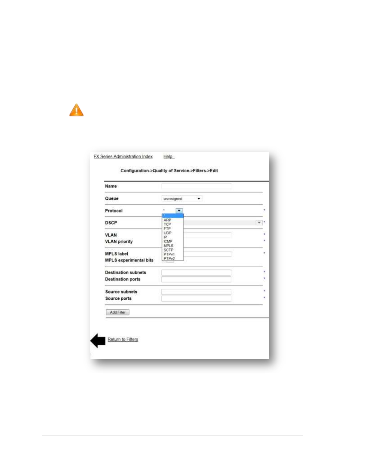
Comtech EF Data / Stampede
4.6.3 QoS Filter Definitions
If the user checks a box and clicks “Add” the rank will be set based upon the rank of the selected item.
Each of those actions lead to a Filter Definition screen. The rules in the pick-list will be sorted based upon
Rank. “Up" and "Down" buttons will appear at the bottom of the pick list to move rules up or down in
priority. An existing entry may be chosen by clicking on the queue name.
The Default filter is a wild card filter that will always be the last filter evaluated. The Default filter maps
data to the Default Queue. This can be reconfigured in the Filter Edit screen.
NOTE: If the FX appliance is positioned between clients and a network device requiring ARP
resolution, such as a router or default gateway, a high priority QoS filter for ARPs should be
defined.
Add QoS Filters
The fields on this screen dictate how traffic will be directed to a queue
Figure 4-10 FX Series QoS Filters Configuration Screen
QoS Filter Definitions
Name:
This summarizes the customer/function of the filter. This field must be entered and must be
unique.
FX Series Administration Guide - Version 6.1.1 68
Chapter: FX Series Network Settings
Section: Configuring Quality of Service with ACM MN-FXSERIESADM6 Rev 5
Page 69
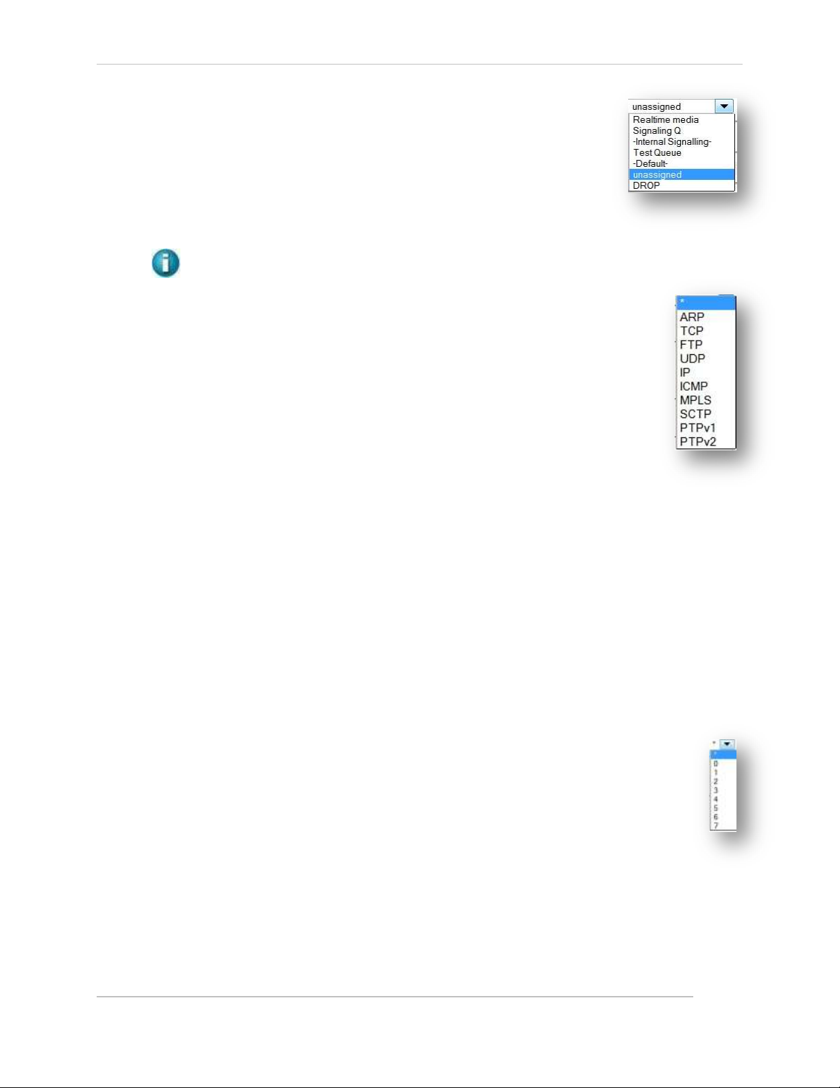
Comtech EF Data / Stampede
Queue:
Selects which queue that traffic that matches the criteria specified in this filter
definition should be directed. This field may be left blank during definition, but
must be eventually be assigned. If the “Drop” option is selected, all traffic
selected by this filter will be dropped. The Default filter will target the Default
Queue, but can be redefined in this screen.
Protocol:
Select between * / ARP / TCP / FTP/ UDP / IP / ICMP / MPLS / SCTP / PTPv1 / PTPv2
NOTES: (only one choice may be selected). The default is * (all protocols)
FTP: If FTP is selected, the FX automatically tracks the data ports associated with FTP
transfers by monitoring the activity on the FTP control port, which is defaulted to
port 21 upon initial selection. To maintain Multicator transmitter functionality when
performing QOS on non standard FTP ports, an additional QOS filter must be created
for FTP that utilizes port 21. The FTP control port may be changed. “For active FTP”,
the source port field should be configured to “20, 21”
MPLS: If MPLS is selected, then the “MPLS Label”, and “MPLS experimental bits”
fields will be enabled as filter criteria, otherwise these fields are disabled. If MPLS is
selected, then additionally the VLAN filter criterion is enabled but all other filter
criteria fields are disabled.
If ARP, PTPv1, PTPv2 or FTP is selected, then this filter can’t be assigned to a queue
for which packet compression is enabled.
PTPv1 or PTPv2 : If PTPv1 or PTPv2 is selected, only DSCP, VLAN, VLAN Priority, Destination subnets,
and Source subnets may be selected. If PTPv2 is selected, in addition to PTPv2 running over UDP, the
filter will also check for packets on ethertype 88f7, in which case IP specific options do not apply.
SCTP: If SCTP is selected, only DSCP, VLAN priority, Destination subnets, and Source subnets may be
selected.
DSCP:
Select one of the choices from the pull-down menu of DCSP choices. Only one choice may be
selected). The default is * (any)
VLAN:
Enter either 0 or a VLAN ID between 2 and 4094. Only one may be selected. 0 indicates untagged
traffic as the selection criteria. The default is * (any VLAN)
VLAN Priority:
Choose between ‘any’ or a priority value between 0 and 7. Only one choice may be
selected. The default is * (any VLAN priority)
MPLS Label:
If MPLS was selected as the protocol then a decimal value between 0 and 1048575 may be
entered. If no value is entered then all MPLS labels will match the filter criteria. If there
are multiple MPLS labels, the filter will only match the first label encountered in the packet.
MPLS experimental bits:
If MPLS was selected as the protocol then you can choose a value between 0 and 7 as match criteria.
If ‘*’ is chosen then the filter does not use the experimental bits in the match criteria, otherwise all
bits must match exactly.
FX Series Administration Guide - Version 6.1.1 69
Chapter: FX Series Network Settings
Section: Configuring Quality of Service with ACM MN-FXSERIESADM6 Rev 5
Page 70
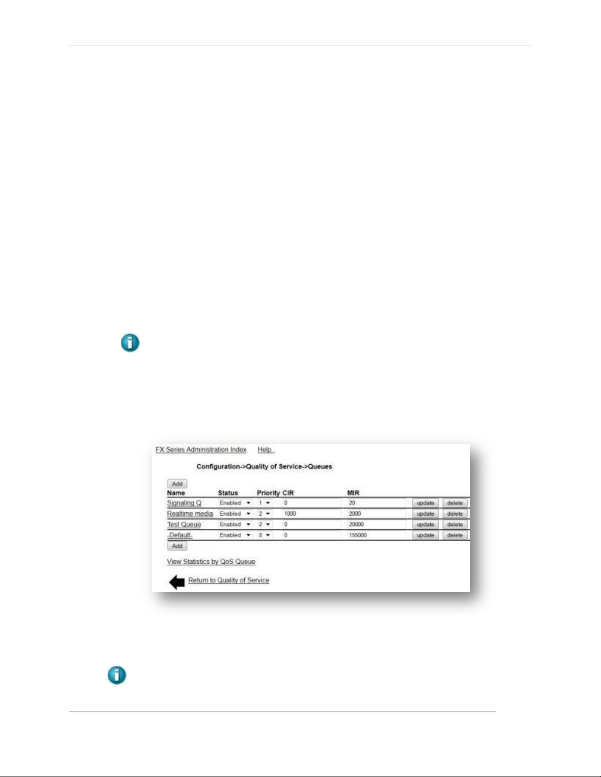
Comtech EF Data / Stampede
Destination Subnets:
This is specified in CIDR format. Multiple subnets may be separated by a comma. The default is ‘*’
(any subnet). Acceleration tunnels utilized by FX WAN Optimization may not maintain the original
application destination address, therefore this field should not be used when classifying FX Wanop
traffic unless an application policy is defined to prevent tunnel sharing between different destination
subnets.
Destination Ports:
Port ranges can be specified by either entering the lowest port followed by ‘-‘, followed by highest
port; or multiple ports may be entered separated by comma. The destination port is relative to the
FX.
Source Subnets:
This is specified in CIDR format. Multiple subnets may be separated by a comma. The default is ‘*’
(any subnet)
Source Ports:
Port ranges can be specified by either entering the lowest port followed by ‘-‘, followed by highest
port; or multiple ports may be entered separated by comma. The source port is relative to the FX.
Acceleration tunnels utilized by FX WAN Optimization do not maintain the original application source
port; therefore this field should not be used when classifying FX Wanop traffic.
When specifying multiple fields as selection criteria the choices are logically “ANDed” when
formulating a match. Multiple selections within a field are logically “ORed” when formulating a
match.
4.6.4 QOS Queue Definitions
These settings allow you to manage QoS Queue Definitions. A list of previously defined queues will be
displayed in order of priority. From this screen the following parameters can be updated: Status, Priority,
Compression CIR, and MIR. Using the pull down options or entering new values in the numeric fields and
clicking the “update” button will update the definition for that specific queue.
Figure 4-11 FX Series Quality of Service Queues
An existing entry may be chosen by clicking on the queue name which leads to the Queues Add/Edit
Screen. The user adds queues by clicking the “Add Queue” button.
NOTE: The Default Queue is always defined. It is initial priority is 8, the lowest priority and is
associated with the Default Filter.
FX Series Administration Guide - Version 6.1.1 70
Chapter: FX Series Network Settings
Section: Configuring Quality of Service with ACM MN-FXSERIESADM6 Rev 5
Page 71
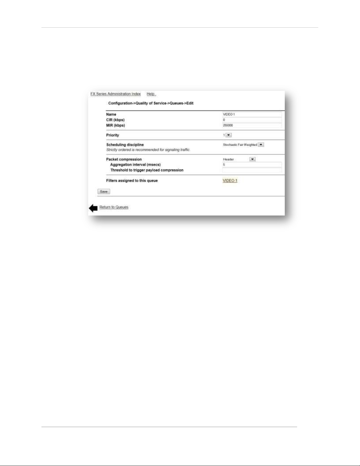
Comtech EF Data / Stampede
View Statistics by QOS Queue
The QOS Status Monitor provides a real time view of vital QoS statistics, including current, average
and elapsed stats. All elapsed and average stats begin with the last Reset of the screen.
See Status Monitor in the Status Section 7.2 below.
Add QoS Queue
Figure 4-12 FX Series Q0S Queues Configuration Screen
Name:
This field is a logical name that is used as a reference when Filters are defined. This field must be entered.
CIR (kbps):
This specifies the “Committed Information Rate” in kbps (1000 bits per second). The range is 0 up to the
licensed rate. If the FX WAN optimization feature is not licensed, then up to 700000 kbps can be specified.
The default is 0. This field is disabled if “Strict Priority” was configured as the drain algorithm.
MIR (kbps):
This specifies the “Maximum Information Rate” in kbps (1000 bits per second). The range is 0 up to the
licensed rate. If the FX WAN optimization feature is not licensed then up to 500000 can be specified. If 0
is specified, some packets may still be sent at a very low rate, to inhibit all traffic then a “DROP” filter
should be defined. The default is the max licensed rate. This field is disabled if “Strict Priority” was
configured as the drain algorithm.
Priority:
This is the drain priority for the queues. Classes of equal priorities will be treated the same, with rates
split proportionally between them. The minimum value is 1 the max is 8. 1 is the highest priority. The
default value is 8.
Scheduling Discipline:
This specifies the order in which packets in this queue are scheduled for transmission.
The default is Stochastic Fair Weighted.
FX Series Administration Guide - Version 6.1.1 71
Chapter: FX Series Network Settings
Section: Configuring Quality of Service with ACM MN-FXSERIESADM6 Rev 5
Page 72

Comtech EF Data / Stampede
The choices are:
Stochastic Fair Weighted
The scheduler will attempt to evenly distribute outbound traffic based on hashing the source and
destination addresses.
This is the default choice and prevents one traffic flow from consuming all bandwidth assigned to this
queue at the expense of other flows assigned to this queue. When there is high link congestion this
method may introduce miniscule delays.
Strictly ordered
Packets are sent in the order that they are received. This may be a good choice for signaling traffic
where there can be absolutely no disruption in packet transmission.
Packet compression:
Enables/disables packet compression and aggregation for this queue. For packet compression to
occur, you must also globally configure packet compression on the ‘Configuration->QoS-
>Dynamic ACM’ page. If packet compression is enabled then WAN optimization features such as
caching can’t be performed on traffic associated with this queue. When configuring packet
compression, you can choose to perform header compression or both header and payload
compression.
Aggregation interval (msecs):
Specifies the packet aggregation flush interval in milliseconds if packet compression is
enabled. The minimum and default value is 10 msecs. The maximum is 1000 msecs.
Threshold to trigger payload compression:
If ‘header and payload’ compression is selected, this value specifies the minimum payload
size to trigger payload compression. The default is 300 bytes.
Filters:
This is a read-only list of filters that are currently assigned to this queue.
FX Series Administration Guide - Version 6.1.1 72
Chapter: FX Series Network Settings
Section: Configuring Quality of Service with ACM MN-FXSERIESADM6 Rev 5
Page 73

Comtech EF Data / Stampede
4.7 FX Series Multicator Overview
The Multicator is a set of three components of the FX Series which allow controlled reliable content
distribution via multicast. These components are as follows:
Multicator Controller (MC)
Within a Multicator deployment, there is one, and only one, FX SERIES ADC appliance which must be
designated as an MC.
An MC is the central point where Multicator configuration parameters are stored. The MC ensures that
only one multicast transmission is occurring at a time. The MC ensures that if there is a network outage, a
multicast which was in progress will resume from the point where the outage occurred. The MC
maintains a central log of all Multicator events.
Multicator Transmitter (MT)
This component actually performs the multicast of the content after checking with the MC. Any FX Series
ADC or FX Series Remote can function as a Multicator Transmitter (MT) if the license is enabled. The MT
employs world renowned open source technology to reliably deliver content via multicast.
NOTE: Any FTP program can be used to upload content to the MT.
Multicator Receiver (MR)
This component receives the content which is transmitted by the MT. Upon completion of a successful
reception of new content, the MR uploads this content to a local FTP server.
NOTE: Any combination of MC, MT, and MR may be configured on the same appliance as long
as there exists one, and only one MC in the Multicator deployment.
FX Series Administration Guide - Version 6.1.1 73
Chapter: FX Series Network Settings
Section: FX Series Multicator Overview MN-FXSERIESADM6 Rev 5
Page 74

Comtech EF Data / Stampede
4.7.1 Theory of Operation
A powerful new content distribution system can now be set up with the separately licensed “Multicator”
feature. This feature allows a user to upload a file to an FX Series device via FTP. The file is then reliably
multicast to a group of receivers. The receivers then upload the content to a local FTP server. The
Multicator employs the “Content Distribution Control Protocol” (CDCP) to ensure that only one multicast
transmission is in progress.
Figure 4-13 FX Series Multicator Theory of Operation
Sequence of Events
1. Files are deposited on the Transmitter (Sender) using a standard FTP client (Site D).
2. The Transmitter then notifies the Controller that it has data to send and is granted permission
to reliably multicast the data across the WAN.
3. Under the direction of the Controller, the Transmitter establishes a reliable multicast
connection to the Receivers.
4. The Transmitter sends the files to each of the Receivers (Sites A, B, C, and E).
5. Each Receiver sends an acknowledgment of receipt to the Controller.
6. Each receiver uses FTP to send the files to the respective server.
FX Series Administration Guide - Version 6.1.1 74
Chapter: FX Series Network Settings
Section: FX Series Multicator Overview MN-FXSERIESADM6 Rev 5
Page 75

Comtech EF Data / Stampede
4.7.2 Multicator Settings
Figure 4-14 FX Series Multicator Configuration Screen (Controller Settings)
Source Interface:
For transmitters and receivers, this is the interface used when communicating with the
controller. For the controller, this is the interface used when transmitters and receivers
communicate
Note: In routed mode this should always be the interface designated as the WAN
interface
Controller Address:
This is the address of the controller that the transmitter/receiver will communicate with. If this device is a
controller and a transmitter or receiver this address should match the "Source Interface" field.
Controller Port:
The port that the controller will use to communicate with transmitters and receivers, if this
appliance is a transmitter or receiver it is the port used to communicate with the controller
Multicator Controller Settings
Enable Multicast Controller:
This setting enables the multicast controller on this appliance. Only one controller
should be enabled on a network. The default is "Disabled".
Multicast Address:
This is the multicast IPv4 address that will be used to transfer files via reliable multicast.
This address is communicated to the transmitters and receivers. The default value is
224.0.55.55.
Multicast Port:
This is the multicast port that will be used to transfer files via reliable multicast. This
port is communicated to the transmitters and receivers. The default value is 4929.
FX Series Administration Guide - Version 6.1.1 75
Chapter: FX Series Network Settings
Section: FX Series Multicator Overview MN-FXSERIESADM6 Rev 5
Page 76

Comtech EF Data / Stampede
Transaction Rate:
This is the max speed that a multicast transmitter will transmit a file. The default value is
based off the license.
Figure 4-15 FX Series Multicator Transmitter/Receiver Configuration Settings
Multicator Transmitter Settings
Enable Multicast Transmitter:
This setting enables the multicast transmitter on this appliance.
Incoming FTP User:
This is the user name that must be used when content is uploaded to the FX appliance.
The default is "mc".
Incoming FTP Password:
This is the password that must be used when content is uploaded to the FX appliance.
The default password is “comtech”.
Multicator Receiver Settings
Enable Multicast Receiver:
This setting enables the multicast receiver on this appliance.
FTP Server:
This is the IP address of the FTP server into which newly received content will be
fanned-out.
FX Series Administration Guide - Version 6.1.1 76
Chapter: FX Series Network Settings
Section: FX Series Multicator Overview MN-FXSERIESADM6 Rev 5
Page 77

Comtech EF Data / Stampede
FTP User: This is the user name used when transferring new content to the FTP server.
FTP Password:
This is the password which will be used when transferring new content to the FTP
server.
FTP Directory:
This optional parameter is the directory where new content will be transferred. If this
directory does not already exist, it will be created before the file is transferred. The
default is none.
FTP Retries:
This is the number of times to attempt to send the file to the FTP server before both
deleting it and moving on to the next or keeping it and moving on to the next. The
receiver will attempt to resend all failed files when the acceleration service is restarted
or the "Retry Failed FTP" button is pressed.
FTP seconds between retries:
This pull-down allows you to select number of seconds which will elapse between each
attempt to send the file to the FTP server.
Action on FTP failure:
This specifies the action to take if the FTP retry limit is exceeded. If delete is selected
the file will be delete, otherwise the file will be stored until the "Retry Failed FTP"
button is clicked or the acceleration service is restarted.
Retry Failed FTP:
This button will cause any files that failed FTP transfer to be re-sent to the FTP server.
This action is only valid if "Action on FTP Failure" is set to "keep"
.
Purge Failed FTP:
This button will delete any files which are pending to be re-sent to the FTP server. This
action is only valid if "Action on FTP Failure" is set to "keep".
Note: If disk utilization reaches 80%, a purge of all files that failed FTP transfer
will automatically occur.
4.7.3 Multicator General Setup (required for all roles)
1. Log into the browser interface of the appliance.
2. Click the Configuration link; Click the Multicator link.
3. Select the appropriate interface in the "Source Interface" field in the "General Settings" section. In
routed mode this should always be the WAN facing interface.
4. Enter the IP address of the controller for the transmitter and receiver in the "Controller Address"
field. If this is the controller enter the IP address in the "Source Interface" field.
5. Enter the port the transmitter/receiver will communicate with the controller on. If this appliance is
also a controller, this is the port it will listen on.
FX Series Administration Guide - Version 6.1.1 77
Chapter: FX Series Network Settings
Section: FX Series Multicator Overview MN-FXSERIESADM6 Rev 5
Page 78

Comtech EF Data / Stampede
4.7.4 Multicator Controller Configuration Setup
1. Log into the browser interface of the appliance.
2. Click the Configuration link; Click the Multicator link.
3. Click the enable radio button in the “Enable Multicast Controller” field in the "Multicator Controller
Section"
4. Enter the multicast IP address you wish to use in the “Multicast Address” field. Default: 224.0.55.55
5. Enter the port you wish to use for multicast in the “Multicast Port” field. Default: 4929
6. Enter the rate at which data should be transmitted via multicast in the “Transaction Rate” field.
Default: The licensed rate of the appliance.
4.7.5 Multicator Receiver Configuration Setup
1. Log into the browser interface of the appliance.
2. Click the Configuration link; Click the Multicator link.
3. Click the enable radio button in the “Enable Multicast Receiver” field in the "Multicator
Receiver" section.
4. Enter the controller port of the Multicator controller. Default: 4929
5. In the “FTP Server” field, enter the IP address of the FTP server that will receive the file
delivered to the receiver via multicast.
6. In the “FTP User” field, enter the user name for the FTP server that will receive the file
delivered to the receiver via multicast.
7. Default: anonymous
8. In the “FTP Password” field, enter the password for the FTP server where the file received
via multicast will be placed.
9. Default: no directory, file deposited in FTP root
10. In the “FTP Directory” field, enter the directory on the FTP server where the file received via
multicast will be placed.
11. In the "FTP Retries" field select the number of times the receiver should attempt to deliver a
file to the FTP server before abandoning the file transfer. Default: 5
12. In the "FTP seconds between retries" field select the number of second between FTP retry
attempts. Default: 10
13. In the "Action on FTP failure" field select the action to be taken on the file if the FTP transfer
fails and all retry attempts have been exhausted. Default: keep
4.7.6 Multicator Transmitter Configuration Setup
1. Log into the browser interface of the appliance.
2. Click the Configuration link; Click the Multicator link.
3. Click the enable radio button in the “Enable Multicast Transmitter” field in the "Multicator
Transmitter" section.
4. Enter the username used in FTP file submissions to the transmitter in the "Incoming FTP
user" field. Default: mc
5. Enter the password used in FTP file submissions to the transmitter in the “Incoming FTP Password”
field. Default: comtech
FX Series Administration Guide - Version 6.1.1 78
Chapter: FX Series Network Settings
Section: FX Series Multicator Overview MN-FXSERIESADM6 Rev 5
Page 79

Comtech EF Data / Stampede
4.8 Redundancy
This section allows you to configure 1:1 redundancy with fail over in which a secondary FX, with the same
configuration as the primary FX, polls for the existence of the primary FX, and takes over its nonmanagement IP addresses when the primary does not respond to the poll. When the primary FX comes
back up, the secondary FX will relinquish the IP addresses. This section also allows you to configure
shared configurations between members of an appliance pool. This is useful to synchronize
configurations in a WCCP cluster.
Figure 4-16 FX Series Redundancy Screen
4.8.1 Redundancy Configuration Settings
Redundancy
This must be enabled if either the 1:1 Redundancy with fail over or “Automatically synchronize
configurations” feature is required.
Primary Appliance:
This is the host name of the primary (master) FX.
Secondary Appliance:
Enter the ‘short’ host name or IP address of the secondary FX that will engage if the primary FX becomes
inoperable. The secondary appliance continually polls the primary appliance and if the primary appliance
does not respond then the secondary appliance asserts control over the realm of IP addresses that
external clients connect to. When the primary appliance becomes operational again, the secondary will
relinquish control of these IP addresses. This parameter is not required if only synchronizing configuration
changes to member pool appliances is being configured.
Authentication Key:
By default, this key is generated automatically. For 1:1 Redundancy with fail over, the secondary
appliance's key must match the primary appliance's key. This requires manually copying the primary
appliance's key and pasting it into this field on the secondary appliance (after deleting the secondary
appliance's generated key).
FX Series Administration Guide - Version 6.1.1 79
Chapter: FX Series Network Settings
Section: Redundancy MN-FXSERIESADM6 Rev 5
Page 80

Comtech EF Data / Stampede
Automatically Synchronize Configuration Changes:
This field must be enabled for configuration synchronization. Any time a configuration change is applied
using the browser administration interface; the change is immediately synchronized with the Secondary
Appliance and/or members of the “Member Appliance Pool”. The ‘Configuring Key-Exchange’ procedure
below must be performed.
Member Appliance Pool:
If the “Automatically Synchronize Configuration Changes” is enabled, then this field defines the list of
host names or IP addresses, separated by commas, of the appliances that will share the same
configuration files as the primary appliance. The devices defined in the “Member Appliance Pool”
share their configurations and require a valid SSH key to be exchanged with the “primary” appliance.
(See section titled “Configuring Key-Exchange” below).
Save Button:
Clicking on ‘Save’ will commit the fields on this form to disk. If this is the Initial configuration of high-
availability the appliance must be rebooted after the ‘Save’ completes.
4.8.2 Configuring Key-Exchange
In order for the FXs to securely communicate with each other in an automated fashion it is necessary to
use the FX-Series Appliance Manager” via SSH to configure common cluster authentication keys.
To configure the key exchange between the primary and secondary, log into the FX with “ssh” to access
the "FX-Series Appliance Manager" and perform the following sequence on the primary FX:
1. Choose “1 Configure Appliance”
2. Then choose “2 Configure Passwords”
3. Then choose “2 Configure Redundancy Cluster Key”
4. Enter the IP Address or host name of the peer appliance
5. On prompt: Are you sure you want to continue connecting (yes/no) enter ‘yes”
6. On the password prompt enter “comtech”
Repeat this for the secondary and/or each entry in the Member Appliance Pool.
NOTE: For 1:1 Redundancy with failover configurations, the primary appliance and secondary appliance
entries must be associated with the auxiliary port. A ‘short’ host name is required. These may be
specified via the DNS server or by configuring the local host table. (See Configuration->Host Settings)
ARP Considerations:
When the FX performs the IP take over it will send out a gratuitous ARP so that other routers are notified
of the take-over.
FX Series Administration Guide - Version 6.1.1 80
Chapter: FX Series Network Settings
Section: Redundancy MN-FXSERIESADM6 Rev 5
Page 81

Comtech EF Data / Stampede
4.8.3 Example 1:1 redundancy with fail over setup scenario
• Given an FX-4000/FX4010 ADC named ‘PrimAdc’ installed and operating in “in-line mode”
eth2/eth3) using eth0 as a management port.
• Add a new FX-4000/FX4010 ADC appliance named ‘Adc2nd’ for 1:1 redundancy with fail
over.
1. Cable the ADC appliances:
a) Connect PrimAdc/Adc2nd auxiliary (eth1) ports with cross-over cable
b) Remove PrimAdc eth3 port connection (Wan) and plug it into Adc2nd eth3 (Wan) port
c) Use cross-over cable and connect PrimAdc’s eth3 to Adc2nd eth2 (Lan) port.
2. Browse to Adc2nd: Configuration->Host Settings:
a) Set ‘Host name’ to Adc2nd
b) In ‘Host File Entries’ add the following lines:
10.1.1.10 PrimAdc.com PrimAdc
10.1.1.11 Adc2nd.com Adc2nd
Click ‘Save’
3. Browse to Adc2nd: Configuration->Basic Network interfaces
Set Auxiliary Interface
‘Ip v4Address’ = 10.1.1.11 ‘Subnet mask’ = 255.255.255.0
Click ‘Save
4. Browse to PrimAdc: Configuration->Basic Network interfaces
Set Auxliary Interface
‘Ip v4Address’ = 10.1.1.10 ‘netmask’ = 255.255.255.0
Click ‘Save’
5. Browse to PrimAdc: Configuration->Host Settings
In ‘Host File entries’ add the following line
10.1.1.11 Adc2nd.com Adc2nd
10.1.1.10 PrimAdc.com
Click ‘Save’
6. On PrimAdc browse to: FX Series Application Delivery Controller-> Configuration->Redundancy
a) Enable ‘Redundancy’
b) Set ‘Primary Appliance’ to PrimAdc
c) Set ‘Secondary Appliance’ to Adc2nd
d) Set "Automatically Synchronize Configuration Changes" to "Enabled"
Click ‘Save’ and refresh the browser screen.
Should see “Authentication Key” similar to:
auth 1
1 sha1 0509160a630240f400ec5e389c942422
The ‘Save’ action will synchronize PrimAdc’s configuration with Adc2nd.
FX Series Administration Guide - Version 6.1.1 81
Chapter: FX Series Network Settings
Section: Redundancy MN-FXSERIESADM6 Rev 5
Page 82

Comtech EF Data / Stampede
7. On Adc2nd browse to:
a) FX Series Application Delivery Controller-> Configuration->Redundancy
Verify that ‘Authentication Key’ matches that shown on the PrimAdc.
Note: If the Keys do not match, copy and paste the Authentication Key from PrimAdc
to Adc2nd then click ‘Save’ on Adc2nd.
It is necessary to reboot both appliances for Redundancy service to run
4.8.4 Synchronizing Configurations in a WCCP Cluster
When multiple FX devices are functioning in a WCCP cluster, each device has unique network settings,
therefore only selected configuration settings are synchronized between the members of the cluster. The
settings which are synchronized include only the following:
· HTTP Application Policies
· L5 Application Policies
· Authorization Realms
· QoS Queue Definitions
· QoS Filters
Of the above, HTTP application policy synchronizations take effect immediately, throughout the cluster,
unless the HTTP policy references a newly defined authorization realm. If an HTTP application policy
references a modified realm then a restart of the acceleration service may be required for the intended
change to take effect. The other settings require a restart of the acceleration service to take effect.
FX Series Administration Guide - Version 6.1.1 82
Chapter: FX Series Network Settings
Section: Redundancy MN-FXSERIESADM6 Rev 5
Page 83
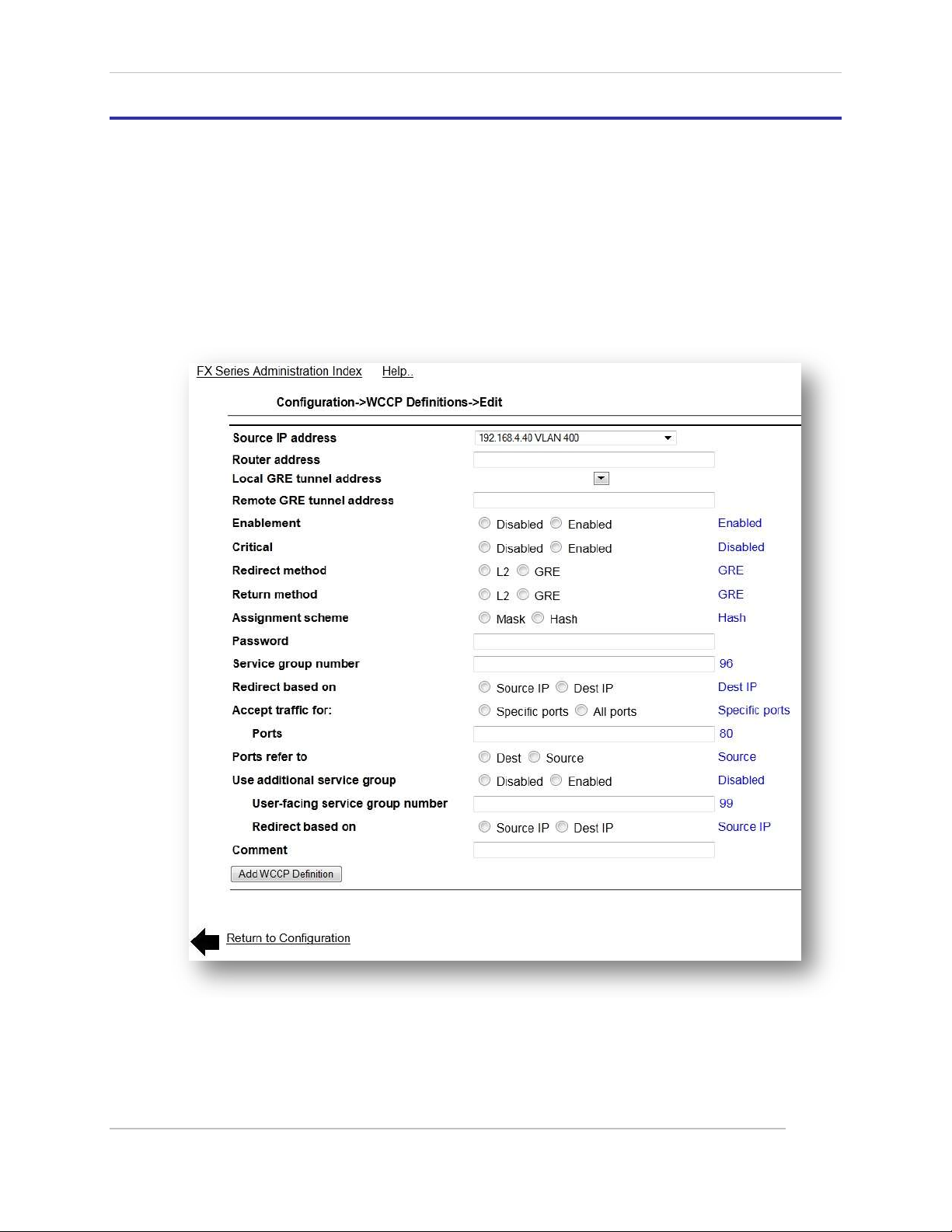
Comtech EF Data / Stampede
4.9 WCCP
The Web Cache Communication Protocol (WCCP) is a Cisco-developed content-routing technology which
allows you to integrate cache engines into your network infrastructure.
This screen allows you to maintain WCCP definitions. A list of previously defined WCCP definitions is
displayed in the order in which they were defined. An existing entry may be chosen by clicking on the
router address. Other buttons at the bottom of the screen are as follows:
Add – Create a new WCCP definition:
Clicking on this button will bring up the following screen.
Figure 4-17 FX Series ADC WCCP Definitions Screen
FX Series Administration Guide - Version 6.1.1 83
Chapter: FX Series Network Settings
Section: WCCP MN-FXSERIESADM6 Rev 5
Page 84

Comtech EF Data / Stampede
4.9.1 WCCP Configuration Considerations
There are two basic configurations that will be used when installing an appliance.
1) Web-cache or transparent proxy interception.
In this mode of interception the FX will have the same characteristics as a standard proxy. The
Cisco device will redirect traffic to the appliance, which will then make request on behalf of the
user using the appliance’s IP address as the source.
NOTE: Only one service group is required, service group zero. On the Cisco device this
will be configured as “web-cache”.
2) Dynamic service groups or source IP address preservation
In this mode of interception the FX will the same characteristics as an in-line device. The Cisco
device will redirect traffic to the appliance, which will then make request on behalf of the user
using the user’s address as the source (spoofing).
NOTE: This configuration requires two service groups, inbound and outbound.
4.9.2 WCCP Cisco Device configuration
We will use either eth0 or eth1 when installing in a WCCP pattern. Log into the Cisco device and identify
the inbound and outbound interfaces. These must correspond to in-path interfaces.
In the global configuration enable WCCP with the appropriate commands.
If configuring as a web-cache we will enter the following:
“ip wccp web-cache”
For a WCCP with source IP address preservation setup. We will enter the following commands:
“ip wccp 99”, “ip wccp 96”
By default our appliances use service groups 99 for outbound traffic and 96 for inbound
traffic.
At the interface level if we are configuring a web-cache setup. We will enter the following
command:
For all inbound interfaces: “ip wccp web-cache redirect in”
At the interface level if we are configuring a source IP address preservation setup. We will enter
the following commands:
For all inbound interfaces: “ip wccp 99 redirect in”
For all outbound interfaces: “ip wccp 96 redirect in”
It is possible to control which traffic is redirected by subnet using the redirect-list option
4.9.3 Web Cache Communication Protocol Parameters
Configuration->WCCP Definitions:
This page allows you to configure the settings for support of the Cisco “Web Cache Communication
Protocol” (WCCP).
Source IP address:
This the IP address, which has already been defined on the FX Series ADC that will be used when
sending WCCP, messages to the router. The IP address must be selected from the list of in-path
interfaces.
FX Series Administration Guide - Version 6.1.1 84
Chapter: FX Series Network Settings
Section: WCCP MN-FXSERIESADM6 Rev 5
Page 85

Comtech EF Data / Stampede
Router address:
This is the address of the router to which WCCP packets will be directed.
Local GRE tunnel address:
This is the IP address of the local end of the GRE tunnel. If this field is not specified then the “Source IP
address” will be used for the local endpoint. This field is not needed if L2 redirection is specified.
Remote GRE tunnel address:
This is the address of the router which will send the redirected traffic to the FX Series ADC in a GRE tunnel.
If this field is not set then the FX will attempt to dynamically learn the address by examining the WCCP
packets from the router. This field is not needed if L2 redirection is specified.
Enablement:
This specifies if this WCCP definition should be processed. The default value is enabled
Critical:
If set, and “Use additional service group” is disabled, then this service group is considered critical. Noncritical service groups will not attempt to negotiate WCCP with the router unless all critical members have
seen their IP address in the assignment map or hash allotment and are in a usable state.
Redirect method:
This specifies the method in which the router or switch will direct packets to the FX. The choices are
“GRE” (Generic Routing Encapsulation) or “L2” which means that the router will simply modify the MAC
destination address to point to the FX. The default is “GRE”.
Return method:
Although the FX never returns redirected packets to the router, it may be necessary to set this to “GRE”
even though “L2” was specified as the redirect method in order to successfully negotiate WCCP.
Assignment scheme:
This specifies how the router or switch will decide which FX to direct the packets. In general, this should
be set to “Mask” for switches and “Hash” for router. The default setting is “Hash”
Password:
If WCCP packet signing is required then this password must match the setting of the WCCP router. The
default is no password.
Service group number:
This is the WCCP service group that the FX should join. The default value is 96.
Redirect based on:
If “source” then the router will redirect responses from the content server to this member, otherwise the
router will redirect client requests that otherwise would have been directed to the content server.
Service groups are defined at the router. The default is the “Destination”.
Accept traffic for:
This radio button allows you to control if only specific ports or all ports should be redirected to the FX
Series FX. If “Specific Ports” selected then these are specified in the “Ports” field. If “All ports” is selected
then the WCCP router will direct all TCP and UDP traffic to the FX. The default value is “Specific Ports”.
FX Series Administration Guide - Version 6.1.1 85
Chapter: FX Series Network Settings
Section: WCCP MN-FXSERIESADM6 Rev 5
Page 86

Comtech EF Data / Stampede
Ports:
This defines the TCP and UDP ports that the router should transparently redirect to the FX. Up to
8 ports may be specified separated by a comma. The default value is 80.
Ports refer to:
This indicates if the ports field pertains to the source port (for responses from content server) or
destination port (for requests from clients). The default value is “Source”.
Use additional service group:
You can define two service groups within the same WCCP definition. This is normally used if you want the
FX to preserve the source IP address of the remote clients when making requests to content servers on
behalf of those clients. However, if using the “extra” group then the definition is not deemed as non critical and will not verify that “critical” service groups are in a usable state. If this is set you must also
enable “Preserve client IP addresses” in the “Other” section on the “Configure->General” page. See more
detailed description titled “WCCP IP Spoofing Configuration” below. The default value is “Disabled”.
User-facing service group:
This is the WCCP service group that the FX should join to receive redirected client. The FX will
not attempt to join this group unless it successfully enrolls in the main service group. This
prevents the situation where client requests are redirected to the FX when it is not able to
receive server responses. The default value is 99.
Comment:
A comment of up 80 characters can be entered into this field.
4.9.4 WCCP Router Configuration and Status Monitoring
Configuration:
The following is an example of some common WCCP Router “cli” commands.
conf t
ip wccp enable
ip wccp version 2
interface (specify interface carrying traffic)
ip web-cache redirect
CTRL-Z
Status Monitoring:
The following WCCP Router “cli” commands can show status:
show ip wccp
show ip wccp 99 view
show ip wccp 96 detail
term mon
debug ip wccp packets
debug ip wccp events
clear ip wccp
FX Series Administration Guide - Version 6.1.1 86
Chapter: FX Series Network Settings
Section: WCCP MN-FXSERIESADM6 Rev 5
Page 87

Comtech EF Data / Stampede
4.9.5 WCCP IP Spoofing Configuration for Routers
The FX can preserve the source IP address of the remote client when making requests on their behalf by
joining two service groups. The first service group receives the redirected client requests and is also
known as the “User-facing” service group. The second is referred to as the “Server-facing” service group
and it receives the redirected server responses. If two or more FXs have joined these service groups, then
the router will be instructed to split the load of the user-facing service group based on source IP address,
and the responses of the server-facing service group will be split based on destination IP address. This
technique ensures that the response will be directed to the same FX that originated the request on behalf
of the remote user.
The recommended router configuration is to use three interfaces, each corresponding to a different
subnet. To illustrate the setup, we provide an example configuration along with a “show running-config”
that is compatible with the default WCCP settings of the FX.
Example:
Interface A: (Ethernet0/0)
This is the user-facing subnet that receives redirected requests from clients.
Interface B: (Ethernet0/1)
This is the server-facing subnet that receives redirected responses from the content server.
Interface C: (Ethernet1/0)
FX subnet
Service group 99
This should be defined to handle redirected outbound requests from the users destined for the
subnets on Interface B. “Interface C” must be excluded from this to avoid loop-backs that would
otherwise occur when FXs spoof the user IP addresses.
Service group 96
Should be defined to handle redirected responses from content servers that would have
otherwise been sent out on “Interface-A”.
The subnets:
A: User (192.168.103.xxx subnet)
B: Content servers - all other subnets via gateway at 192.168.101.158
C: FXs (192.168.106.xxx)
#show running-config
Building configuration...
Current configuration: 948 bytes
!
version 12.2
service timestamps debug uptime
service timestamps log uptime
no service password-encryption
!
hostname 2600-lab
FX Series Administration Guide - Version 6.1.1 87
Chapter: FX Series Network Settings
Section: WCCP MN-FXSERIESADM6 Rev 5
Page 88

Comtech EF Data / Stampede
!
enable password xxxx
!
memory-size iomem 10
ip subnet-zero
ip wccp 96
ip wccp 99
!
!
no ip domain-lookup
ip domain-name example.enterprise.com
ip name-server 192.168.101.202
!
!
interface Ethernet0/0
ip address 192.168.103.224 255.255.255.0
ip wccp 96 redirect out
half-duplex
!
interface Ethernet0/1
ip address 192.168.101.224 255.255.255.0
ip wccp 99 redirect out
half-duplex
!
interface Ethernet1/0
ip address 192.168.106.224 255.255.255.0
ip wccp redirect exclude in
half-duplex
!
ip classless
ip route 0.0.0.0 0.0.0.0 192.168.101.158
ip http server
ip pim bidir-enable
FX Series Administration Guide - Version 6.1.1 88
Chapter: FX Series Network Settings
Section: WCCP MN-FXSERIESADM6 Rev 5
Page 89

Comtech EF Data / Stampede
4.9.6 WCCP IP Spoofing Configuration for Switches
Switches tend to have less CPU power than a router but on the other hand they have the ability to handle
traffic flow decisions in hardware. In order to leverage the hardware switching capabilities the following
configuration settings are recommended:
On the FX, use “L2” Redirection method
On the FX, use “Mask” assignment scheme
On the FX, do not define separate service group definition records, instead set the “Use
additional service group field”, this is because the Cisco L2 expects the same WCCP source port
to be used to conduct WCCP negotiations.
On the switch, use “redirect in” to direct packet flow to the appliance.
On the switch, never use “redirect-out”
On the switch, do not use “redirect exclude in”
In the same subnet scenario described above, the following is an example of a configuration for an
intelligent switch:
#show running-config
.
.
.
!
ip routing
ip wccp 96
ip wccp 99
!
interface Vlan1
ip address 192.168.101.225 255.255.255.0
ip wccp 96 redirect in
!
interface Vlan3
ip address 192.168.103.225 255.255.255.0
ip wccp 99 redirect in
!
interface Vlan5
ip address 192.168.105.225 255.255.255.0
!
interface Vlan6
description for 106 subnet
ip address 192.168.106.225 255.255.255.0
!
Using “redirect-list” to select specific redirection
For testing purposes, or to gradually stage traffic redirection to the FX Series ADC, a Cisco router will
support redirection by either access control lists or group lists. For example:
ip wccp 99 redirect-list access-list
FX Series Administration Guide - Version 6.1.1 89
Chapter: FX Series Network Settings
Section: WCCP MN-FXSERIESADM6 Rev 5
Page 90

Comtech EF Data / Stampede
4.9.7 LAN and In-Path Interface Requirements for WCCP
The FX Series uses the eth2 physical interface to conduct the WCCP protocol with the router or
switch and also to receive redirected requests and responses. Therefore in order to configure
WCCP, you must define an in-path interface with an IP address that is on the same subnet as the
Cisco router or switch. The gateway for this in-path interface must be that of the Cisco router or
switch interface the appliance is connected to. The VLAN ID must be 0. Following this, a LAN
interface must be defined for eth3 and assigned to the aforementioned In-Path interface.
4.9.8 Configuring WCCP on earlier models
On FX-1000 and some earlier models of FX-4000, the specialized fail-to-wire network interface
card requires that an eth3 LAN interface be defined in order to run WCCP over eth2, even though
it’s not actually used. Therefore, on an FX-1000, an in-path interface with a non-existent VLAN
must be defined. This in-path interface must subsequently be assigned to a LAN interface for
eth3. It is not required that the eth3 physical interface be cabled to anything.
FX Series Administration Guide - Version 6.1.1 90
Chapter: FX Series Network Settings
Section: WCCP MN-FXSERIESADM6 Rev 5
Page 91
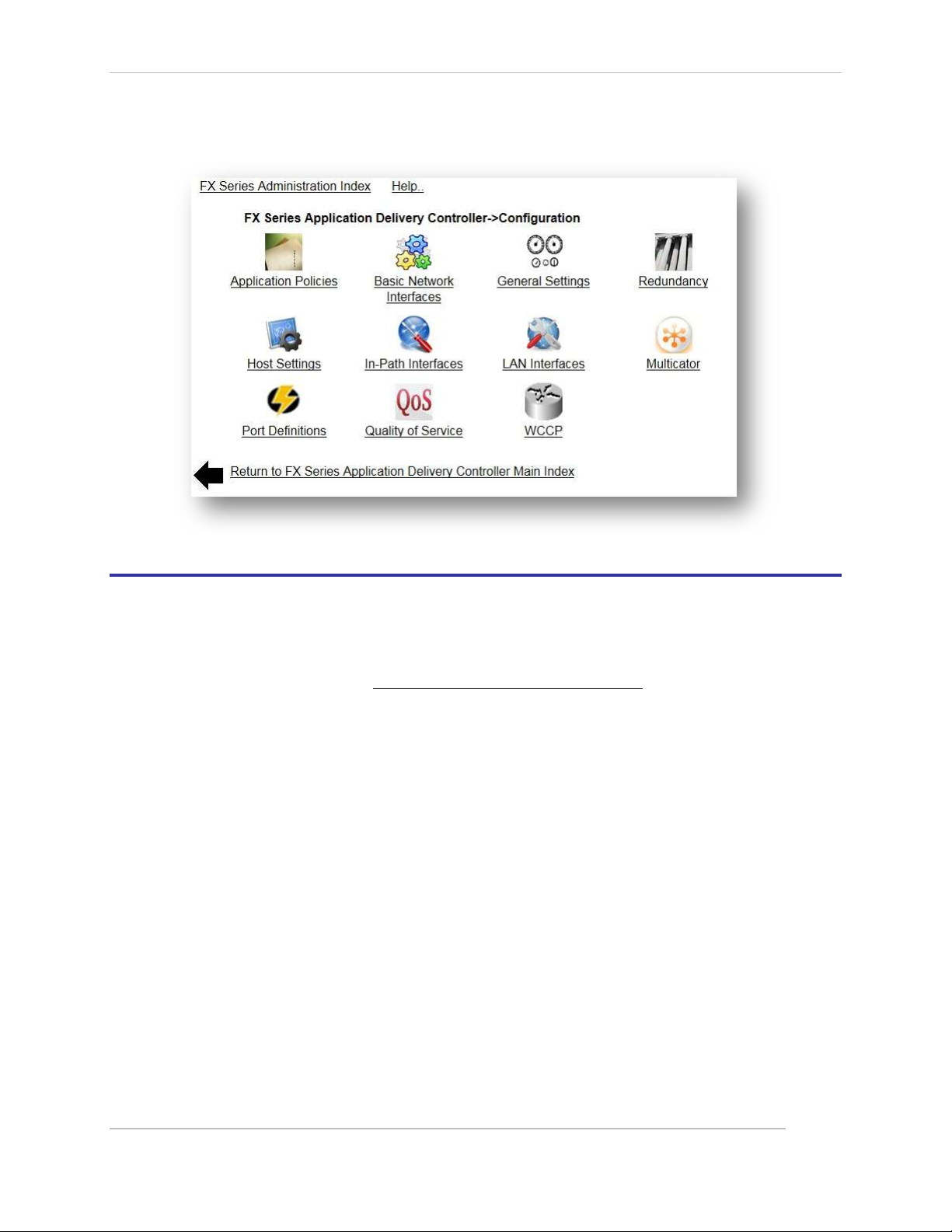
Comtech EF Data / Stampede
5 FX Series ADC Specific Settings
5.1 Overview
This chapter discusses in much greater detail, General Settings and Port Definitions of the FX Series ADC
appliances. The key elements are listed below.
The following items are listed in Section 4 FX Series Basic Network Settings.
Basic Network Interfaces
Redundancy
Host Settings
LAN Interfaces
Multicator
In-Path Interfaces
Quality of Service
WCCP
FX Series ADC General
Control enablement of DDS, and the traffic interception method. Configure basic HTTP settings and
system time.
FX Series ADC Port Definitions
Figure 5-1 FX Series ADC Configuration Menu
Define the IP addresses and ports that the FX will listen on for the purpose of optimizing data flow to a
web or application server. FX Series ADC General Configuration Settings
These settings allow you to configure advanced parameters that apply to many aspects of the FX Series
application delivery controller (FX Series ADC).
FX Series Administration Guide - Version 6.1.1 91
Chapter: FX Series ADC Specific Settings
Section: Overview MN-FXSERIESADM6 Rev 5
Page 92

Comtech EF Data / Stampede
5.1.1 General Settings
Figure 5-2 FX Series ADC General Settings Screen
FX Series ADC in “config-only” Mode:
This setting is useful if you are in the process of configuring your FX Series ADC while the unit is
networked in-line. In “Configuration-Only” mode the in-line networking card is put into “bypass” mode so
that traffic is simply passed through. When you are satisfied that the FX Series ADC is properly configured
you can disable this setting. The default setting is “Disabled”.
Enable Dynamic Data Suppression:
This is a global switch that applies to all traffic processed by this FX Series ADC. If “Enabled” then a cache
of data and signatures and byte patterns will be maintained and when possible a signature will be sent
instead of a redundant byte pattern. The default value is “Enabled”.
FX Series Administration Guide - Version 6.1.1 92
Chapter: FX Series ADC Specific Settings
Section: Overview MN-FXSERIESADM6 Rev 5
Page 93

Comtech EF Data / Stampede
HTTP Session Inactive Timeout (seconds):
This setting controls the maximum time that inactive browser sessions are kept open before closing them
in order to minimize thread and TCP session resources. The default interval value is 60 seconds.
HTTP Server Connect Timeout (seconds):
This controls the maximum number of seconds that the FX Series ADC will wait for a TCP connection to
complete to an HTTP content server before timing-out. After the timeout, a 503 HTTP error code will be
returned to the browser that initiated the request. The default value is 20 seconds.
Generate HTML error pages:
This controls whether the FX Series ADC should generate an HTML page describing the problem and
identifying the FX Series ADC when it encounters a problem connecting and/or receiving content from a
back-end server. The default value is “Enabled”.
Preserve Client IP Addresses:
If enabled, then the FX Series ADC will send the requests to the back-end servers with a source IP address
that is the same as the client that the request is on behalf of. Enabling this setting may require a
Transparent Bridging configuration. This setting only applies to single-sided optimization. IP source
preservation with FX Remotes is specified in the L5 application policies. The default value is “Enabled”.
5.1.2 Object Retrieval Logging
Log HTTP Requests:
Enables logging of URLs for all HTTP web object retrievals in “common log format”. The default setting is
“On”.
Maximum Size in KB
This sets the maximum size of the object retrieval log file in kilobytes. When this size is reached
a backup is made and the file is reset. The default setting is 1000000 (1 GB).
5.1.3 Traffic Interception
Traffic interception mode:
This is the means by which the FX-ADC will transparently intercept packets. Choose
either “In-Line”, “Routed”, WCCP” or “Disabled”. The default is “In-Line”.
In-Line mode, the LAN port is eth2 and the WAN port is eth3. Traffic is
intercepted as a transparent bridge. If there is a service disruption then the
units will “fail-to-wire”. In bridged mode, you must assign an IP address to the in-path interface
which bridges the LAN and WAN interfaces. In FX nomenclature, the “WAN” interface is
considered to be the interface which is connected to the satellite modems and the LAN interface
is connected to the internet or to enterprise servers.
In routed mode, traffic must be directed to these interfaces by a router. You must assign an IP
address to the in-path interface which will receive traffic from the router. There is no “fail-towire” capability if there is a service disruption.
In WCCP mode, traffic is redirected to the FX by a Cisco router via WCCP.
If “Disabled” then traffic redirection is effectively shut off.
VLAN mode:
This controls how the FX will process VLAN tags. In 'Trunk' mode, the VLAN tags are already embedded in
the packets when they are intercepted by the FX. In 'Access' mode, the FX will add tags to untagged
traffic. The default setting is ‘Trunk’.
Note: Changing either the ‘Traffic interception mode’ or ‘VLAN mode’ settings will automatically
trigger a restart of the acceleration service.
FX Series Administration Guide - Version 6.1.1 93
Chapter: FX Series ADC Specific Settings
Section: Overview MN-FXSERIESADM6 Rev 5
Page 94

Comtech EF Data / Stampede
Fail-to-wire mode:
If enabled, the FX will go into bypass mode it is not accelerating traffic or if it is powered off. If
disabled, it will not go into bypass mode which will prevent packets from being forwarded
through the FX. If the FX is adding the VLAN tags to the traffic, it may be desirable to disable
'Fail-to-wire' mode to prevent untagged traffic from entering a network. The default setting is
“Enabled”.
Note: The FX-1010 does not support fail-to-wire mode
5.1.4 System Time
Network Time Server
This setting will specify the host address for which the FX Series ADC will attempt to synchronize its time
via the “Network Time Protocol”. The FX Series ADC performs this synchronization one minute following a
restart and once per week thereafter.
Time Zone
This selector allows you to specify a time zone in which the FX Series ADC resides. In most cases, the
default value of UTC-0 (GMT) is desirable because this will facilitate correlating system events with
troubleshooting and other logs.
5.1.5 Software Updates
Automatically Distribute FX Series Remote Updates:
If “enabled”, then the FX-Remote devices will periodically check to see if a newer version of firmware is
available. If so, the FX-Remote devices will automatically download and apply the firmware update. The
default value is “Disabled”. It is a recommended practice that this setting be enabled only when you wish
to deploy updated FX firmware during off-peak hours.
5.1.6 Administration
Use SSL for the administrative Web GUI:
If “enabled” then HTTP/S must be used when managing the FX from the Web graphical user interface.
This is a recommended practice to prevent passwords from being transmitted unencrypted. The default
value is “Enabled”.
5.1.7 Other
Use Spanning-Tree Protocol:
If enabled, then spanning-tree protocol (STP) will be used when operating in “in-line” mode.
Otherwise STP packets will be discarded. The default value is “Enabled”.
NOTE: If this setting is changed, then it is necessary to restart the acceleration software on the
“Status->Real-time Monitor” screen.
FX Series Administration Guide - Version 6.1.1 94
Chapter: FX Series ADC Specific Settings
Section: Overview MN-FXSERIESADM6 Rev 5
Page 95

Comtech EF Data / Stampede
5.2 Port Definitions
Port definitions allow you to define which IP address and port combinations that the FX Series ADC will
listen on and what protocols should be accepted over these combinations. A port definition is required
for every IP address and port combination on which the FX Series ADC will accept connections in a proxy
mode. For each port definition you must specify the protocol that will be used. Port definitions are on ly
needed if you will be directing traffic to the FX Series ADC as a proxy, or from a remote software client
that is running acceleration plug-in.
This screen allows you to maintain Port definitions. A list of previously defined Port definitions is
displayed in the order in which they were defined. An existing entry may be chosen by clicking on the
port. You can “Enable”, “Disable”, or “Delete” one or more Port definitions by selecting the checkbox to
the left of the port column and clicking on the desired button. By clicking on “Add” you can add a new
port definition which will bring up the port definition screen.
Figure 5-3 FX Series ADC Port Definitions Screen
5.2.1 In-Path Interface:
Specify the IP address that is associated with this port definition.
Port:
This field will be filled in automatically as you set the “Protocol” field. After setting these fields, you can
then override the port field to create a unique IP Address / Port combination.
Protocol:
This specifies the protocol that will run over this port. There are the following choices:
HTTP:
This choice specifies that you want the ADC to function as either a forward or reverse proxy on
this port.
FX Series Administration Guide - Version 6.1.1 95
Chapter: FX Series ADC Specific Settings
Section: Port Definitions MN-FXSERIESADM6 Rev 5
Page 96

Comtech EF Data / Stampede
IP
Port
Protocol - SLL
Typical Use
any
80
HTTP / Acc.
HTTP - Autosense
Transparent redirection with capability to
inject AOD.
any
8080
HTTP
Forward proxy of HTTP traffic from standard
browsers
any
4917
Acc. HTTP/L5
Accelerated traffic between standard and
advanced clients and FX Series ADC
Accelerated HTTP/L5:
This choice specifies that you want the ADC to use this port to service the HTTP Acceleration
Protocol (HAP) that has been extended to also accelerate non-HTTP TCP/IP based protocols at
layer 5. Accelerated HTTP/L5 is only available if you have deployed the acceleration plug-in to
your remote users.
Autosense:
This setting supports the AOD injection where both HTTP traffic and accelerated HTTP can flow
over the same port.
Comment:
This provides a place to store any user defined comment to describe the rationale for this port definition.
Status:
This allows you to control whether this port definition is enabled or disabled.
5.2.2 Example Port Definitions
By default, port definitions are not required to function as a one-sided FX Series ADC or as a head-end
serving FX Series Remote appliances.
The table below shows port definition setting examples:
5.2.3 Setting up an HTTP Forward Proxy
A forward proxy requires that an end user specifically set their browser proxy settings such that port 80
traffic is specifically directed to the IP address of an in-path interface of the ADC on a specific port (usually
8080). In order to get this to work some additional steps are required:
1. An L5 Policy must be defined for port 8080 traffic.
2. This L5 policy must have the “certified application” set as “HTTP Traffic”.
3. This L5 policy must have “Protocol” defined as “Generic TCP”.
The “Protocol” on the “Port Definition” must be defined as “HTTP”.
FX Series Administration Guide - Version 6.1.1 96
Chapter: FX Series ADC Specific Settings
Section: Port Definitions MN-FXSERIESADM6 Rev 5
Page 97
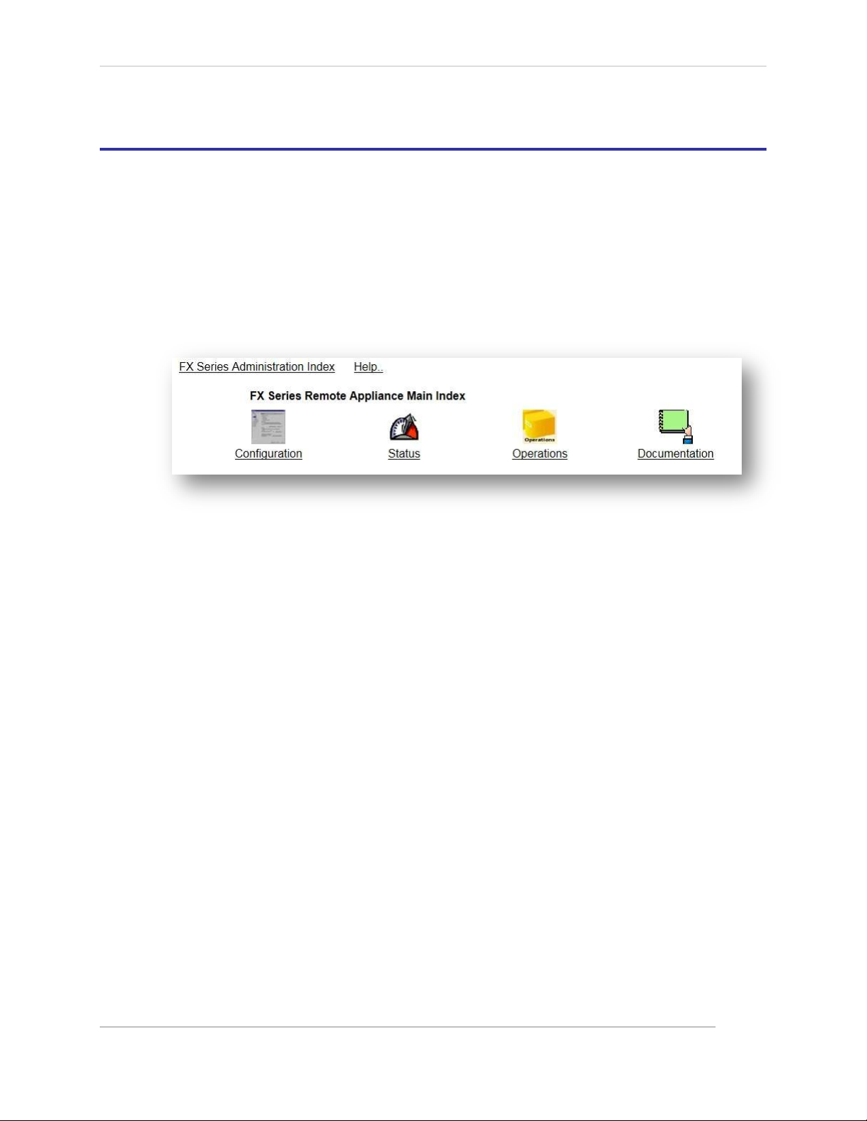
Comtech EF Data / Stampede
6 FX Series Remote Specific Settings
6.1 FX Remote Settings Overview
The FX Series Remote appliance works in conjunction with a head-end FX Series ADC appliance. The FX
Series (ADC) appliance resides at the data center and supports connections with multiple remote sites
where FX Series Remote appliances are installed. Most FX Series Remote configurations are accomplished
with an easy-to-use browser-based tool to set polices on the appliance. The configuration policies are
designed to provide full inheritance properties, meaning that most configuration settings are shared
between all FX Series Remote appliances, but individual over-rides can be set for specific FX Series
Remote appliances.
Figure 6-1 FX Series Remote Main Index Screen
This is the main menu for performing administration on the FX Series Remote (REM) that features the
best enterprise application data communication optimization technology in the industry.
Configuration:
Customize the configuration for your environment by editing networking settings, and Traffic Classes.
Status:
This provides a real-time status monitor and allows you to easily restart the acceleration service. View
activity logs. (See FX Series Status)
Operations:
The following actions are included: Shutdown/Restart the appliance. Backup/Restore configuration files.
Obtain packet capture. Manage license files. (See FX Series Operations Functions)
Documentation:
Access the documentation in PDF format. (See FX Series Documentation)
FX Series Administration Guide - Version 6.1.1 97
Chapter: FX Series Remote Specific Settings
Section: FX Remote Settings Overview MN-FXSERIESADM6 Rev 5
Page 98
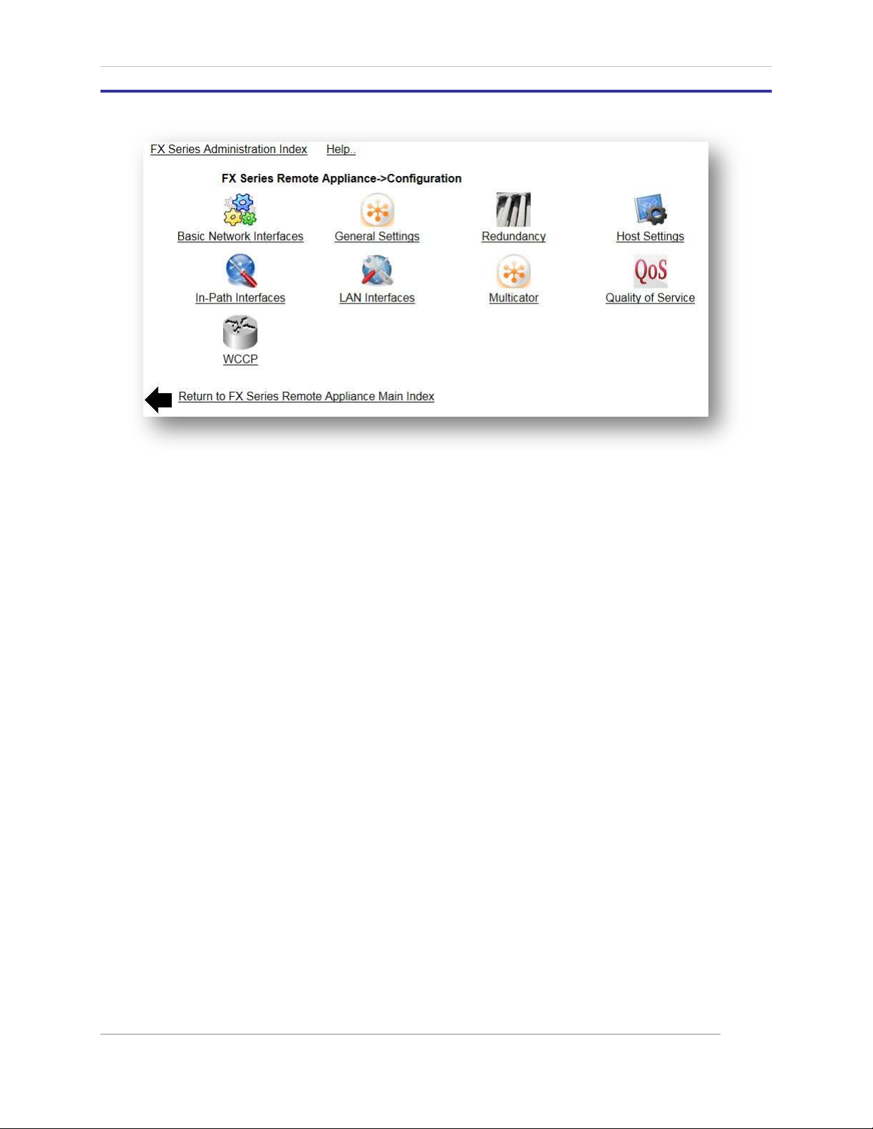
Comtech EF Data / Stampede
6.2 FX Series Remote Configuration Settings
Figure 6-2 FX Series Remote Configuration Screen
These settings allow you to customize the configuration for your environment.
Note the following are common for both the FX Series ADC and the FX Series Remote.
The details can be reviewed in FX Series Basic Networking Settings Section.
• Basic Network Interfaces
• Redundancy
• Host Settings
• LAN Interfaces
• Multicator
• Quality of Service
• WCCP
The following configuration settings are included in this section
General Settings
Control method of traffic interception. Configure basic HTTP settings, system time and other options.
In-Path Interfaces
Configure network settings for the interfaces which will carry accelerated traffic.
FX Series Administration Guide - Version 6.1.1 98
Chapter: FX Series Remote Specific Settings
Section: FX Series Remote Configuration Settings MN-FXSERIESADM6 Rev 5
Page 99

Comtech EF Data / Stampede
6.2.1 FX Series Remote General Settings
Figure 6-3 FX Series Remote General Settings Screen
6.2.2 System Time
Network Time Server:
Specify the host address for which the FX Series Remote will attempt to synchronize its time via the
“Network Time Protocol”. The FX Series Remote performs this synchronization one minute following a
restart and once per week thereafter.
Time Zone:
This selector allows you to specify a time zone in which the FX Series Remote resides. In most cases, the
default value of UTC-0 (GMT) is desirable because this will facilitate correlating system events with
troubleshooting and other logs.
6.2.3 Traffic Interception
FX Remote is in “Configuration-Only” mode:
This setting is useful if you are in the process of configuring your FX Remote while the unit is networked as
a bridge. In “Configuration-Only” mode the bridge networking card is put into “bypass” mode so that
traffic is simply passed through. When you are satisfied that the FX Remote is properly configured you
can disable this setting. The default setting is “Off”.
Traffic Interception Mode:
This is the means by which the FX Series Remote will transparently intercept
packets.
Choose either “In-Line”, “Routed”, WCCP” or “Disabled”. The default is “In-
Line”.
FX Series Administration Guide - Version 6.1.1 99
Chapter: FX Series Remote Specific Settings
Section: FX Series Remote Configuration Settings MN-FXSERIESADM6 Rev 5
Page 100

Comtech EF Data / Stampede
In-Line Mode:
In In-lined mode, the LAN port is eth2 and the WAN port is eth3. Traffic is intercepted as a
transparently. If there is a service disruption then the units will “fail-to-wire”. For in-line mode,
you must assign an IP address to the in-path interface which bridges the LAN and WAN
interfaces. In FX nomenclature, the “WAN” interface is considered to be the interface which is
connected to the satellite modems and the LAN interface is connected to the internet or to
enterprise servers or clients.
Routed Mode:
In routed mode, traffic must be directed to these interfaces by a router. You must assign an IP
address to the in-path interface which will receive traffic from the router. There is no “fail-towire” capability if there is a service disruption.
WCCP Mode:
In WCCP mode, traffic is redirected to the FX by a Cisco router via WCCP.
Disabled Mode:
If “Disabled” then traffic redirection is effectively shut off.
VLAN mode:
Controls how the FX will process VLAN tags. In 'Trunk' mode, the VLAN tags are already embedded in the
packets when they are intercepted by the FX. In 'Access' mode, the FX will add tags to untagged traffic.
The default setting is ‘Trunk’.
Note: Changing either the ‘Traffic interception mode’ or ‘VLAN mode’ settings will automatically
trigger a restart of the acceleration service.
Fail-to-wire mode:
If enabled, the FX will go into bypass mode it is not accelerating traffic or if it is powered off. If disabled, it
will not go into bypass mode which will prevent packets from being forwarded through the FX. If the FX is
adding the VLAN tags to the traffic, it may be desirable to disable 'Fail-to-wire' mode to prevent untagged
traffic from entering a network. The default setting is “Enabled”.
NOTE: The FX-1010 does not support fail-to-wire mode.
6.2.4 Administration
Use SSL for the administrative Web GUI:
If “enabled” then HTTP/S must be used when managing the FX from the Web graphical user interface.
This is a recommended practice to prevent passwords from being transmitted unencrypted.
The default value is “Enabled”.
6.2.5 Other
Use Spanning-Tree Protocol:
If enabled, then spanning-tree protocol (STP) will be used when operating in “bridged” mode. Otherwise
STP packets will be discarded. The default value is “Enabled”.
NOTE: If this setting is changed, it is necessary to restart the acceleration software on the “Status-
>Real-time Monitor” screen or disable and then re-enable each in-path interface.
FX Series Administration Guide - Version 6.1.1 100
Chapter: FX Series Remote Specific Settings
Section: FX Series Remote Configuration Settings MN-FXSERIESADM6 Rev 5
 Loading...