

Comnet CNGE2+2SMS, CNGE2+2SMSPOE, CNGE2+2SMSPOEHO, CNGE4+2SMSPOE, CNGE4+2SMS Installation And Operation Manual
...Page 1

INSTALLATION AND OPERATION MANUAL
CNGE2+2SMS[POE][HO]
10/100/1000 MBPS INTELLIGENT REDUNDANT RING
GIGABIT SWITCH WITH OPTIONAL POE+
This manual serves the following
ComNet Model Numbers:
CNGE2+2SMS
CNGE2+2SMSPOE
CNGE2+2SMSPOEHO
The ComNet CNGE2+2SMS[POE][HO] is a four port intelligent switch with light
management functionality. It provides two 10/100/1000Base-T(X) copper ports and
two 100/1000Base-FX SFP ports. The CNGE2+2SMS[POE][HO] provides exclusive
functionality for easy field deployment including DIP switch based operation of
RSTP for creating redundant network topologies as well as preventing network video
flooding of multicast traffic with IGMP snooping. Ports 1 and 2 can optionally supply
up to thirty (30) watts of power per port based on the IEEE 802.3at standard. An
optional High Output (HO) version is also available that can supply up to sixty (60)
watts of PoE from ports 1 and 2. This product is fully compatible with the ComNet
exclusive CopperLine® SFP modules for operation over extended distance UTP or Coax
cable. The ComNet exclusive Port Guardian feature provides additional cyber security
protection by enabling physical port lockout in the event that an existing cable is
disconnected and prevents a potential network incursion using common spoofing
techniques. The intrusion event is reported back to the operator using SNMP.
Page 2

INSTALLATION AND OPERATION MANUAL CNGE2+2SMS[POE][HO]
Contents
Regulatory Compliance Statement 4
Warranty 4
Disclaimer 4
Safety Indications 4
Overview 5
Introduction 5
Software Features 5
Hardware Features 6
Hardware Overview 7
Side Panels 7
Indicating LEDs 10
Cables 11
Ethernet Cables 11
10/100/1000BASE-T(X) Pin A ssignments 11
SFP 13
Console Cable 13
DIP Switches 14
WEB Management 22
Configuration by Web Browser 22
System Information 25
Switch Port Configuration 26
Port Statistics 27
RSTP System Configuration 28
RSTP Port Configuration 29
LLDP 30
Active Ping Check Configuration 31
Non PoE Model CNGE2+2SMS 31
PoE Model CNGE2+2SMSPOE and CNGE2+2SMSPOEHO 32
Authentication Username and Password Configuration 33
Upgrade Firmware 34
TECH SUPPORT: 1.888.678.9427
INS_CNGE2+2SMS_REV– 02/19/13 PAGE 2
Page 3

INSTALLATION AND OPERATION MANUAL CNGE2+2SMS[POE][HO]
Factory Defaults 35
System Reset 36
Network Interface Configuration 37
SNMP 38
SNMP – Config 38
CNGE2+2SMSPOE[HO] PoE-PSE-Status Information 39
CNGE2+2SMSPOE[HO] PoE Contact Information 40
Port Guardian 41
Port Guardian – CLI Reset 42
Static Multicast MAC Routing Per Port 43
Static MAC Lock Configuration 44
IGMPv2 Snooping 45
Jumbo Frame support 47
Command Line Interface Management 48
Configuration by Command Line Interface (CLI). 48
Firmware Upgrade Procedure 51
Technical Specifications 52
TECH SUPPORT: 1.888.678.9427
INS_CNGE2+2SMS_REV– 02/19/13 PAGE 3
Page 4

INSTALLATION AND OPERATION MANUAL CNGE2+2SMS[POE][HO]
Regulatory Compliance Statement
Product(s) associated with this publication complies/comply with all applicable regulations. Please
refer to the Technical Specifications section for more details.
Warranty
ComNet warrants that all ComNet products are free from defects in material and workmanship
for a specified warranty period from the invoice date for the life of the installation. ComNet will
repair or replace products found by ComNet to be defective within this warranty period, with
shipment expenses apportioned by ComNet and the distributor. This warranty does not cover
product modifications or repairs done by persons other than ComNet-approved personnel, and
this warranty does not apply to ComNet products that are misused, abused, improperly installed,
or damaged by accidents.
Please refer to the Technical Specifications section for the actual warranty period(s) of the
product(s) associated with this publication.
Disclaimer
Information in this publication is intended to be accurate. ComNet shall not be responsible for its
use or infringements on third-parties as a result of its use. There may occasionally be unintentional
errors on this publication. ComNet reserves the right to revise the contents of this publication
without notice.
Safety Indications
» The equipment can only be accessed by trained ComNet service personnel.
» This equipment should be installed in secured location.
TECH SUPPORT: 1.888.678.9427
INS_CNGE2+2SMS_REV– 02/19/13 PAGE 4
Page 5

INSTALLATION AND OPERATION MANUAL CNGE2+2SMS[POE][HO]
Overview
Introduction
The CNGE2+2SMS is a light managed, hardened Ethernet switch that contains many features.
The switch will work under a wide variety of temperature, dirty and humid conditions. It can be
managed through WEB, USB Console or other third-party SNMP software. With the easy to use
and intuitive web and CLI interfaces, the switch can be easily monitored by a utility called eVision,
which is part of the ComNet eConsole software suite.
eConsole is network management software that is very effective. With easy to use and intuitive
interface, you can easily monitor the status of the switches.
Software Features
» Supports SNMPv1/v2c
» Event notification by SNMP trap and Relay Output (Relay Output for PoE models only)
» Web-based GUI and USB Console CLI configuration
» Enable/disable ports
» LLDP (Link Layer Discovery Protocol) support (802.1AB)
» PoE status monitoring and health check
» RS TP (802.1w)
» IGMP snooping v2 (64 groups)
» Jumbo Frame support (10240 MTU)
» Static MAC lock (per port)
» Static multicast MAC routing
» Field firmware upgrade capable
» Port Guardian physical port lockout feature
» Active ping check with SNMP trap, port reset & port shutdown capability
TECH SUPPORT: 1.888.678.9427
INS_CNGE2+2SMS_REV– 02/19/13 PAGE 5
Page 6

INSTALLATION AND OPERATION MANUAL CNGE2+2SMS[POE][HO]
Hardware Features
» 7 × DIP Switches for quick feature selection
» 2 × Redundant DC power inputs
» Operating Temperature: -40 – 75ºC
» Storage Temperature: -40 – 85ºC
» Operating Humidity: 5% – 95%, non-condensing
» 2 × 10/100/1000Base-T(X) Gigabit Ethernet port
» 2 × 100/1000Base-X SFP
» 2 × Dry Contact Inputs (PoE models only)
» 2 × Form A Relays (PoE models only)
» USB Console Port
» Dimensions: 4.1 × 3.7 × 1.46 in (10.4 × 9.4 × 3.7 cm)
TECH SUPPORT: 1.888.678.9427
INS_CNGE2+2SMS_REV– 02/19/13 PAGE 6
Page 7

INSTALLATION AND OPERATION MANUAL CNGE2+2SMS[POE][HO]
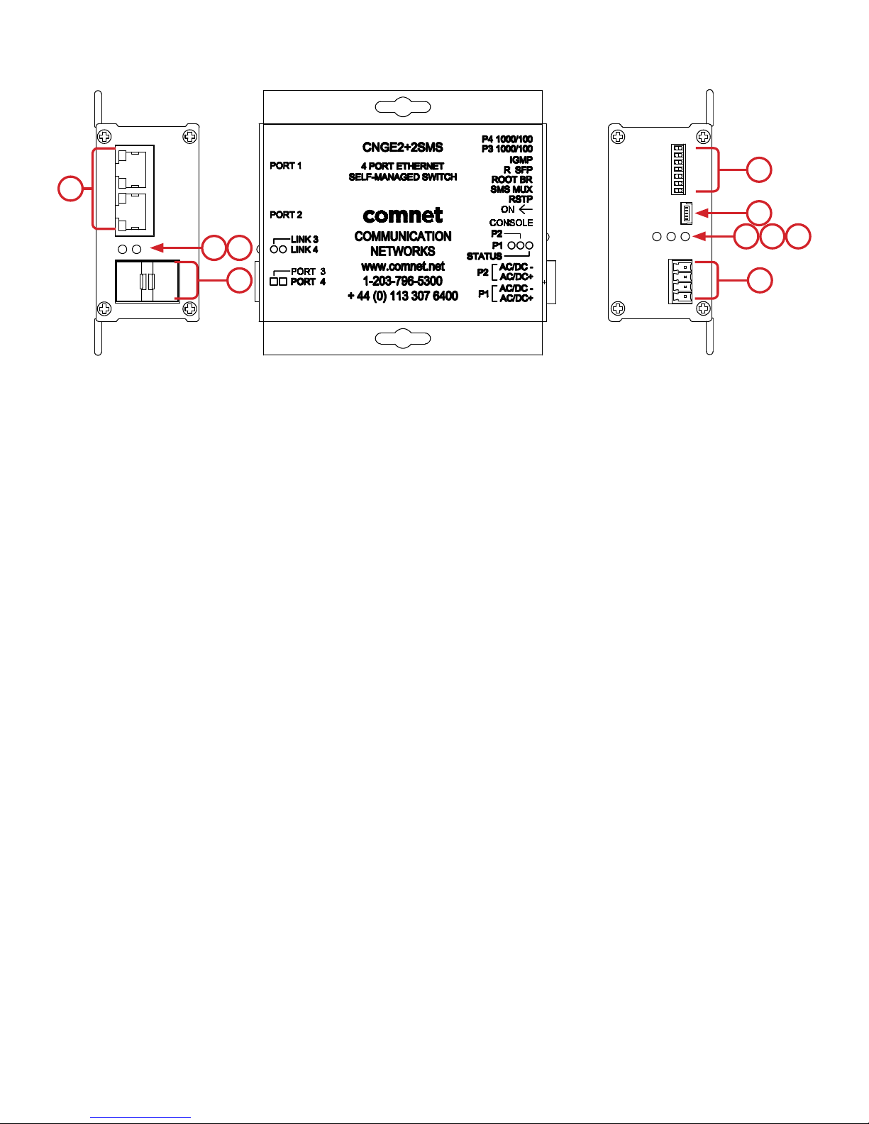
Hardware Overview
Side Panels
The following table describes the ports that are on the sides of the CNGE2+2SMS.
Port Description
10/100/10 00Base-T(X)
RJ-45 Ethernet ports
SFP Ports 2 × 100/1000Base-X SFP
USB Console Use the included mini USB cable to manage the switch.
2 × 10/100/1000Base-T(X) RJ-45 fast Ethernet ports support
auto-negotiation.
Default Settings:
Speed: auto
Duplex: auto
Flow control: disable
TECH SUPPORT: 1.888.678.9427
INS_CNGE2+2SMS_REV– 02/19/13 PAGE 7
Page 8
INSTALLATION AND OPERATION MANUAL CNGE2+2SMS[POE][HO]
1
7
2
98
3 4 5
10
1. Configuration DIP switches
2. Console Mini USB
3. LED for PWR1
4. LED for PWR2
5. LED for STATUS
6. Power Connections
7. RJ-45 Ports
8. Link/Activity LEDs for SFP Port 3
9. Link/Activity LEDs for SFP Port 4
6
CNGE2+2SMS
10. SFP Ports
TECH SUPPORT: 1.888.678.9427
INS_CNGE2+2SMS_REV– 02/19/13 PAGE 8
Page 9

INSTALLATION AND OPERATION MANUAL CNGE2+2SMS[POE][HO]
10
9
9
11
12
13
CNGE2+2SMSPOE
10
11
12
13
3
2
1
3
2
1
4
5
6 7 8
4
5
6 7 8
CNGE2+2SMSPOEHO
1. Power connections
2. Contact IN terminal block
3. Contact OUT terminal block
4. Configuration DIP switches
5. Console Mini USB
6. LED for Power 1
7. LED for Power 2
8. LED for Status
9. RJ-45 Ports
10. PoE Status LEDs for RJ-45 Port 1
11. PoE Status LEDs for RJ-45 Port 2
12. Link/Activity LEDs for SFP Ports 3 and 4
13. SFP Ports 3 and 4
TECH SUPPORT: 1.888.678.9427
INS_CNGE2+2SMS_REV– 02/19/13 PAGE 9
Page 10

INSTALLATION AND OPERATION MANUAL CNGE2+2SMS[POE][HO]
Indicating LEDs
LED Color Status Description
PWR1 Green On DC Power Input 1 Good
Off No power detected
PWR2 Green On DC Power Input 2 Good
Off No power detected
STATUS Green On Initialization passed
Red On Failed
10/100/1000Base-T(X) Ethernet ports
LNK /ACT Green On Port link up
Blinking Data transmitting
1000 Mbps indicator Amber On Port speed is 1000 Mbps
30W Green On 30W PoE power being supplied (POE units only)
60W Green On 60W PoE power being supplied (POEHO units only)
SFP
LNK /ACT Green On Port link up.
Blinking Data transmitted.
TECH SUPPORT: 1.888.678.9427
INS_CNGE2+2SMS_REV– 02/19/13 PAGE 10
Page 11

INSTALLATION AND OPERATION MANUAL CNGE2+2SMS[POE][HO]
Cables
Ethernet Cables
The CNGE2+2SMS switches have standard Ethernet ports. According to the link type, the switches
use CAT 3, 4, 5, & 5e UTP cables to connect to any other network device (PCs, servers, switches,
routers, or hubs). Please refer to the following table for cable specifications.
Cable Types and Specifications
Cable Type Max. Length Connector
10BASE-T Cat. 3, 4, 5 100Ω UTP 100m (328ft) RJ-45
100BA SE-TX Cat. 5 100Ω UTP UTP 100m (328ft) RJ-45
1000BASE-TX Cat. 5/Cat. 5e 100Ω UTP UTP 100m (328ft) RJ-45
10/100/1000BASE-T(X) Pin Assignments
With 100BASE-T(X)/10BASE-T cable, pins 1 and 2 are used for transmitting data, and pins 3 and 6
are used for receiving data.
10/100 Base-T RJ-45 Pin Assignments
Pin Number Assignment
1 TD+
2 TD-
3 RD+
4 Not used
5 Not used
6 RD-
7 Not used
8 Not used
Note: “+” and “-” signs represent the polarity of the wires that make up each wire pair.
TECH SUPPORT: 1.888.678.9427
INS_CNGE2+2SMS_REV– 02/19/13 PAGE 11
Page 12

INSTALLATION AND OPERATION MANUAL CNGE2+2SMS[POE][HO]
1000 Base-T RJ-45 Pin Assignments
Pin Number Assignment
1 BI_DA+
2 BI_DA-
3 BI_DB+
4 BI_ DC+
5 BI_DC-
6 BI_DB-
7 BI_DD+
8 BI_DD-
The CNGE2+2SMS switches support auto MDI/MDI-X operation. You can use a straight-through
cable to connect PC to switch. The following table below shows the 10/100BASE-T(X) MDI and
MDI-X port pin-outs:
10/100 Base-T MDI/MDI-X pin assignments
Pin Number MDI port MDI-X port
1 TD+ (transmit) RD+ (receive)
2 TD- (transmit) RD- (receive)
3 RD+ (receive) TD+ (transmit)
4 Not used Not used
5 Not used Not used
6 RD- (receive) TD- (transmit)
7 Not used Not used
8 Not used Not used
1000 Base-T MDI/MDI-X pin assignments
Pin Number MDI port MDI-X port
1 BI_DA+ BI_DB+
2 BI_DA- BI_DB-
3 BI_DB+ BI_DA+
TECH SUPPORT: 1.888.678.9427
4 BI _ DC+ BI_DD+
5 BI_DC- BI_DD-
6 BI_DB- BI_DA-
7 BI_DD+ BI _DC+
8 BI_DD- BI_DC-
INS_CNGE2+2SMS_REV– 02/19/13 PAG E 12
Page 13
INSTALLATION AND OPERATION MANUAL CNGE2+2SMS[POE][HO]
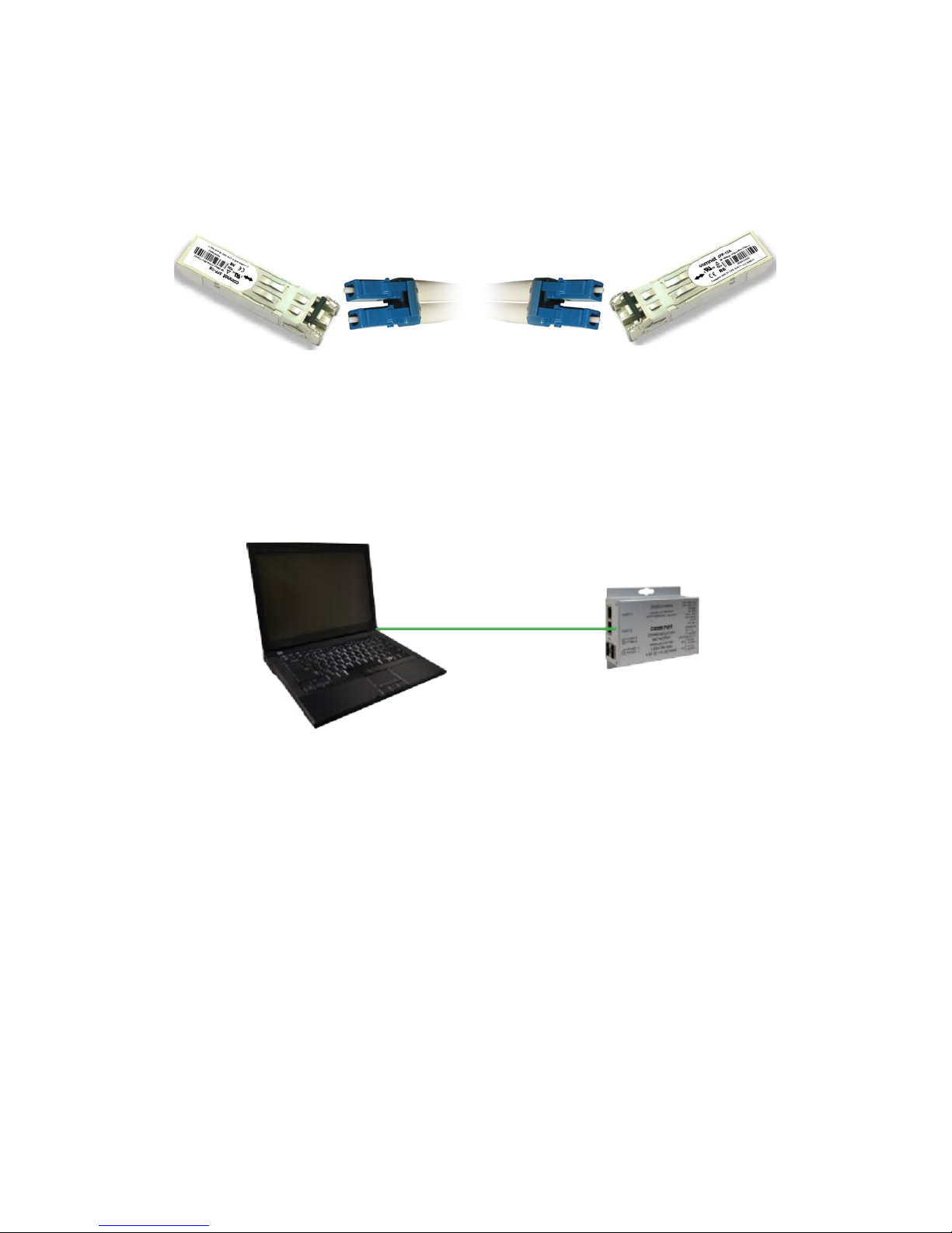
SFP
The Switch has fiber optic ports that utilize SFP connectors. ComNet offers a wide selection of SFP
modules that offer different fiber type, connector type and distances. Please remember that the
TX port of Switch A should be connected to the RX port of Switch B.
Switch A Fiber Cord Switch B
Console Cable
Each CNGE2+2SMS switch can have the initial network settings configured by the management
console port. You can connect them to a PC with USB Ports using the supplied USB to USB Mini B
male plug cable.
USB to USB Mini B Cable
TECH SUPPORT: 1.888.678.9427
INS_CNGE2+2SMS_REV– 02/19/13 PAG E 13
Page 14

INSTALLATION AND OPERATION MANUAL CNGE2+2SMS[POE][HO]
DIP Switches
The CNGE2+2SMS’s dip switches configure switch features. The DIP Switches are numbered from
left to right when viewing the side of the Switch with the backplate on the bottom and the power
connections on the left. If “Web Management Enable” is selected in the management software
under System Settings, the DIP switch settings will be overridden by any settings made in the
browser interface.
DIP Switch
Position Description
1 RSTP enable (down = disabled, up enabled)
2 Port SMS Mux
3 Root Bridge Select
4 Redundant SFP mode
5 IGMP enable
6 SFP Port 3 speed. Up: 1000M/Down: 100M
7 SFP Port 4 speed. Up: 1000M/Down: 100M
Switch Function Listing
The switch functions may be set individually or may be combined in the following order to perform
enhanced functions above the individual operation. The table below describes the operation of the
switch functions. This same table is also available in the help menu of the system webpage.
Summary of the switch configurations (in order of switch priority)
RSTP
(Switch 1)
ON OFF OFF OFF RSTP All ring configurations
ON OFF ON OFF RSTP RSTP this bridge set to root
OFF ON OFF OFF SMS
SMS MUX
(Switch 2)
ROOT BR
(Switch 3)
R SFP
(Switch 4)
Resulting Mode Comment
Port4 is uplink (traffic from
ports 1-3 is sent only to port 4)
OFF ON OFF ON
OFF OFF OFF ON Redundant SFP
TECH SUPPORT: 1.888.678.9427
SMS with
Redundant SFP
Fiber fail over
with Port1 and Port2 isolation
Fiber fail over
Port 4 is primary port
INS_CNGE2+2SMS_REV– 02/19/13 PAGE 14
Page 15

INSTALLATION AND OPERATION MANUAL CNGE2+2SMS[POE][HO]
SMS MUX Disabled (DIP Switch 2 in OFF Position)
SMS MUX Enabled (DIP Switch 2 in On Position)
TECH SUPPORT: 1.888.678.9427
INS_CNGE2+2SMS_REV– 02/19/13 PAG E 15
Page 16
INSTALLATION AND OPERATION MANUAL CNGE2+2SMS[POE][HO]
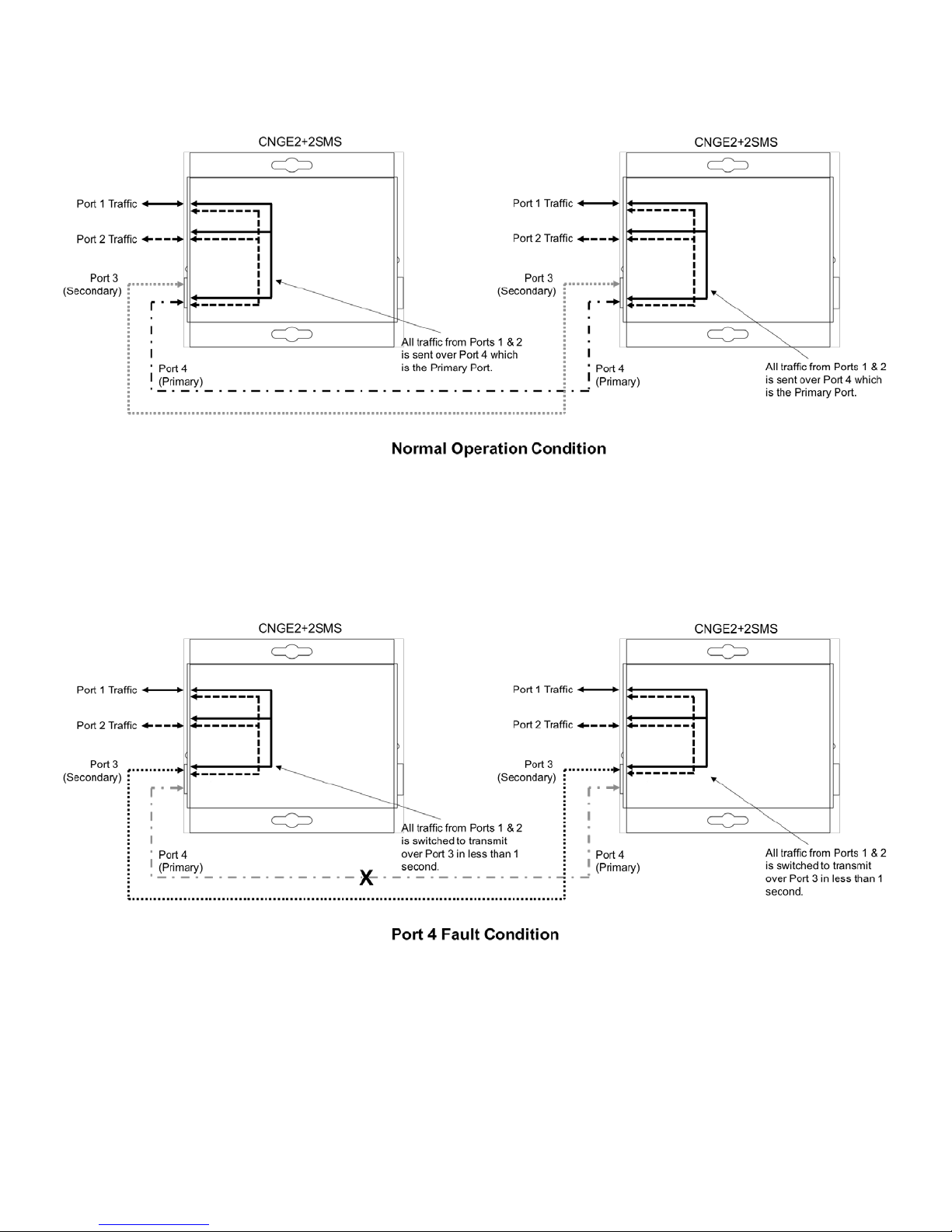
Redundant SFP (RSFP) Enabled (DIP Switch 4 in On Position)
Note: There is no port isolation between Ports 1 & 2 as shown. Ports 1 & 2 are free to send traffic
between each other as per a normal switch.
Redundant SFP (RSFP) Enabled (DIP Switch 4 in On Position)
Note: There is no port isolation between Ports 1 & 2 as shown. Ports 1 & 2 are free to send traffic
between each other as per a normal switch.
When Port 4 comes back online all traffic from Ports 1 & 2 is switched back to transmit
over Port 4 in less than 1 second.
TECH SUPPORT: 1.888.678.9427
INS_CNGE2+2SMS_REV– 02/19/13 PAG E 16
Page 17

INSTALLATION AND OPERATION MANUAL CNGE2+2SMS[POE][HO]
Redundant SFP (RSFP) Enabled (3rd Party Switch) (DIP Switch 4 in On Position)
Note: Disabling MAC Address Learning on the 3rd party switch (if supported) can sometimes
allow for faster port switchover times.
There is no port isolation between Ports 1 & 2 as shown. Ports 1 & 2 are free to send traffic
between each other as per a normal switch.
When Port 4 comes back online all traffic from Ports 1 & 2 is switched back to transmit
over Port 4 in less than 1 second.
TECH SUPPORT: 1.888.678.9427
INS_CNGE2+2SMS_REV– 02/19/13 PAG E 17
Page 18

INSTALLATION AND OPERATION MANUAL CNGE2+2SMS[POE][HO]
Redundant SFP (RSFP) Enabled + SMS MUX Enabled (3rd Party Switch) (DIP Switch 2 & 4 ON)
Note: Disabling MAC Address Learning on the 3rd party switch (if supported) can sometimes
allow for faster port switchover times.
Multicast traffic is diverted only to port 4 preventing flooding on the local device between
Ports 1 & 2. Ports 1 & 2 are isolated from each other.
When Port 4 comes back online all traffic from Ports 1 & 2 is switched back to transmit
over Port 4 in less than 1 second.
TECH SUPPORT: 1.888.678.9427
INS_CNGE2+2SMS_REV– 02/19/13 PAGE 18
Page 19

INSTALLATION AND OPERATION MANUAL CNGE2+2SMS[POE][HO]
RSTP Enabled (Single Ring) (DIP Switch 1 ON)
See Note
Below
Attention: ComNet recommends maximum number of units per ring is limited to 20 devices.
Numbers higher than this may cause undesired performance and are not supported
by ComNet.
Note: The unit at the control room location should have DIP switch 3 ON (ROOT BR). This will
force the ring to break at the half way point and ensure most effective load sharing on the
network.
TECH SUPPORT: 1.888.678.9427
INS_CNGE2+2SMS_REV– 02/19/13 PAG E 19
Page 20

INSTALLATION AND OPERATION MANUAL CNGE2+2SMS[POE][HO]
RSTP Enabled (Multiple Rings) (DIP Switch 1 ON)
Attention: ComNet recommends maximum number of units per ring is limited to 20 devices.
Numbers higher than this may cause undesired performance and are not supported
by ComNet.
Attention: Central switch must be manually configured to be the root bridge. This requirement is
mandatory for correct performance in a multiple ring scenario.
Attention: ComNet recommends maximum number of rings per core switch is limited to 3-4.
The actual number supported will depend on the processing power of the core switch
used and other features that may be enabled on the core switch. Please contact
ComNet Technical Support to discuss your application prior to ordering.
TECH SUPPORT: 1.888.678.9427
INS_CNGE2+2SMS_REV– 02/19/13 PAGE 20
Page 21

INSTALLATION AND OPERATION MANUAL CNGE2+2SMS[POE][HO]
IGMP & RSTP Enabled (DIP Switch 1 & 5 ON)
Important Note: The CNGE2+2SMS supports IGMP snooping only. When using the IGMP
function a managed switch must be implemented within the network that is
configured as the IGMP Querier as shown.
Up to 64 IGMP groups are supported on the CNGE2+2SMS switch.
TECH SUPPORT: 1.888.678.9427
INS_CNGE2+2SMS_REV– 02/19/13 PAGE 21
Page 22

INSTALLATION AND OPERATION MANUAL CNGE2+2SMS[POE][HO]
WEB Management
Attention: While installing and upgrading firmware, please remove physical loop connection first.
DO NOT power off equipment while the firmware is upgrading!
Configuration by Web Browser
This section provides instruction on configuration through the Web browser.
About Web-based Management
An embedded HTML web site resides in the flash memory on the CPU board. It contains
advanced management features and allows you to manage the switch from anywhere on the
network through a standard web browser such as Microsoft Internet Explorer.
The Web-Based Management function supports Internet Explorer 5.0 or later.
Preparing for Web Management
The default value is as below:
IP Addre ss : 19 2.16 8.10.1
Subnet Mask: 255.255.255.0
Default Gateway: 192.168.10.254
User Name: admin
Password: admin
TECH SUPPORT: 1.888.678.9427
INS_CNGE2+2SMS_REV– 02/19/13 PAGE 22
Page 23

INSTALLATION AND OPERATION MANUAL CNGE2+2SMS[POE][HO]
System Login
1. Launch your Web Browser.
2. Type http:// and the IP address of the switch. Press Enter.
3. The login screen appears.
4. Enter username and password. The default username and password is admin.
5. Select Enter or OK button, then the main interface of the Web-based management appears.
Login screen
TECH SUPPORT: 1.888.678.9427
INS_CNGE2+2SMS_REV– 02/19/13 PAGE 23
Page 24

INSTALLATION AND OPERATION MANUAL CNGE2+2SMS[POE][HO]
Main Interface
Main interface
TECH SUPPORT: 1.888.678.9427
INS_CNGE2+2SMS_REV– 02/19/13 PAGE 24
Page 25

INSTALLATION AND OPERATION MANUAL CNGE2+2SMS[POE][HO]
System Information
The switch system information is provided here.
System Information interface
Label Description
Switch Settings Summary table of external switch settings
Web Management Enable Override the side panel switches setting to use the webpage settings instead.
Switch override Override individual switch functions
Enabled protocols Summary table of enabled protocols
Temperature Unit’s internal board temperature reading
Port link status Link status and port disable
TECH SUPPORT: 1.888.678.9427
INS_CNGE2+2SMS_REV– 02/19/13 PAGE 25
Page 26

INSTALLATION AND OPERATION MANUAL CNGE2+2SMS[POE][HO]
Switch Port Configuration
Unless you have reason to change this setting, it is recommended to leave the negotiation set to
auto.
The link segment requires forcing the settings. Both ends of the link need to have the same
selection.
SwitchPort Configuration interface
TECH SUPPORT: 1.888.678.9427
INS_CNGE2+2SMS_REV– 02/19/13 PAGE 26
Page 27

INSTALLATION AND OPERATION MANUAL CNGE2+2SMS[POE][HO]
Port Statistics
Use the refresh button to update the port statistics.
Port Statistics interface
TECH SUPPORT: 1.888.678.9427
INS_CNGE2+2SMS_REV– 02/19/13 PAGE 27
Page 28

INSTALLATION AND OPERATION MANUAL CNGE2+2SMS[POE][HO]
RSTP System Configuration
The Rapid Spanning Tree Protocol (RSTP) is an evolution of the Spanning Tree Protocol. It provides
faster spanning tree convergence after a topology change. The system also supports STP and the
system will auto detect the connected device that is running STP or RSTP protocol.
RSTP System configuration interface
Label Description
Enable RSTP Select to enable RSTP (only available when the DIP switch settings
have been overridden by web management mode. See Page 26.)
Priority Configure bridge priority, must be a multiple of 4096. If the ROOT BR
dip switch is enabled this value will be set to 4096. If the ROOT BR dip
switch is disabled this value will be set to 32768 by default.
Root Bridge ID MAC address of the root bridge
Important Note: RSTP cannot be used in conjunction with the Static MAC Lock feature.
A system reset must be performed after making changes to the RSTP settings.
TECH SUPPORT: 1.888.678.9427
INS_CNGE2+2SMS_REV– 02/19/13 PAGE 28
Page 29

INSTALLATION AND OPERATION MANUAL CNGE2+2SMS[POE][HO]
RSTP Port Configuration
RSTP Port configuration interface
Label Description
Port Priority Configure port priority, must be a multiple of 16.
Port Admin Configure port Admin or Auto Edge status.
Port Status Summary table of RSTP port status
Important Note: A system reset must be performed after making changes to the RSTP settings.
TECH SUPPORT: 1.888.678.9427
INS_CNGE2+2SMS_REV– 02/19/13 PAGE 29
Page 30

INSTALLATION AND OPERATION MANUAL CNGE2+2SMS[POE][HO]
LLDP
LLDP (Link Layer Discovery Protocol) function allows the switch to advertise its information to other
nodes on the network and store the information it discovers.
LLDP is enabled by default with the interval set to 10 seconds.
LLDP configuration interface
TECH SUPPORT: 1.888.678.9427
INS_CNGE2+2SMS_REV– 02/19/13 PAGE 30
Page 31

INSTALLATION AND OPERATION MANUAL CNGE2+2SMS[POE][HO]
Active Ping Check Configuration
Non PoE Model CNGE2+2SMS
The active ping check function allows the switch to check that a configured IP address is alive
on each of the RJ45 ports. If the specified IP address becomes unreachable then the switch will
perform the action selected in the Failure Action menu.
Active Ping Check configuration interface
Label Description
Enable Select to enable the active ping check function
Interval Active ping check interval in seconds
Remote IP Configure IP addresses of remote device to ping
Failure action Configure action to take upon failure
No Action - No action taken
SNMP Trap - Issue an SNMP trap
Power Down - Turn off the RJ45 port
PwrDwn & Trap - Issue an SNMP trap and then turn off the RJ45 port
Retries Number of times to retry the ping check on failure before proceeding with the selected
failure action.
TECH SUPPORT: 1.888.678.9427
INS_CNGE2+2SMS_REV– 02/19/13 PAGE 31
Page 32

INSTALLATION AND OPERATION MANUAL CNGE2+2SMS[POE][HO]
PoE Model CNGE2+2SMSPOE and CNGE2+2SMSPOEHO
Label Description
Enable Select to enable the active ping check function
Interval Active ping check interval in seconds
Remote IP Configure IP addresses of remote device to ping
Failure action Configure action to take upon failure
No Action - No action taken
SNMP Trap - Issue an SNMP trap
POE Reset - Reboot the PoE device
Trap & Reset - Issue an SNMP trap and then reboot the PoE device
Power Down - Turn off the RJ45 port
PwrDwn & Trap - Issue an SNMP trap and then turn off the RJ45 port
Retries Number of times to retry the ping check on failure before proceeding with the selected
failure action.
PoE Action PoE action to take
Reset Once - Reboot the PoE device once
Reset Forever - Reboot the PoE device forever until it comes back online
Power Down - Turn off the RJ45 port
If power down is selected for PoE action, the PoE power may be turned on remotely using the port
power up feature on the PoE-PSE status page.
TECH SUPPORT: 1.888.678.9427
INS_CNGE2+2SMS_REV– 02/19/13 PAGE 32
Page 33

INSTALLATION AND OPERATION MANUAL CNGE2+2SMS[POE][HO]
Authentication Username and Password Configuration
The username and password entered here are also used in the CLI.
Authentication Username and Password configuration interface
TECH SUPPORT: 1.888.678.9427
INS_CNGE2+2SMS_REV– 02/19/13 PAGE 33
Page 34

INSTALLATION AND OPERATION MANUAL CNGE2+2SMS[POE][HO]
Upgrade Firmware
Upgrade Firmware allows you to update the firmware of the switch. Before updating, have your
Windows firmware update application ready and the firmware image is available. RSTP is not
available during the firmware update process so please, observe the network topology before
upgrading.
Update Firmware interface
Details on how to upload the new image is located in Firmware Upgrade section on Page 51.
After applying a new firmware version, it is recommended that a Factory Default Reset is
performed to ensure that all new or adjusted settings take effect. Please note that performing a
Factory Default reset will erase all the devices settings except for the IP address.
Warning Do not enable the firmware update process unless you have a firmware file available
and are ready to upgrade the unit. Once this processed is started it cannot be cancelled
and if a new firmware is not uploaded to the unit it will be necessary to return the unit
to the factory for re-programming.
TECH SUPPORT: 1.888.678.9427
INS_CNGE2+2SMS_REV– 02/19/13 PAGE 34
Page 35

INSTALLATION AND OPERATION MANUAL CNGE2+2SMS[POE][HO]
Factory Defaults
Factory Defaults Reset interface
This function restores the system configuration back to the factory default values. All parameters
will revert back to the original factory default values except the network configuration settings.
TECH SUPPORT: 1.888.678.9427
INS_CNGE2+2SMS_REV– 02/19/13 PAGE 35
Page 36

INSTALLATION AND OPERATION MANUAL CNGE2+2SMS[POE][HO]
System Reset
System Reset interface
This feature will perform a system reset.
Some system configuration changes require a system reset to take effect:
-RSTP changes
-File System updates
-Network configuration changes
- IGMP changes
- Static Mack Lock changes
- Static Mcast routing
After a system reset there may be a delay of up to 15 seconds before the device becomes
responsive again.
TECH SUPPORT: 1.888.678.9427
INS_CNGE2+2SMS_REV– 02/19/13 PAGE 36
Page 37

INSTALLATION AND OPERATION MANUAL CNGE2+2SMS[POE][HO]
Network Interface Configuration
Interface Configuration interface
Label Description
Host Name Assign a name to the device (this is used for CLI and SNMP functions)
Enable DHCP To enable or disable the DHCP client function. When DHCP client
function is enabled, the switch will be assigned the IP address from the
network DHCP server. The default IP address will be replaced by the IP
address which the DHCP server has assigned.
IP Address Assign the IP address that the switch will use. If DHCP client Function is
enabled, you do not need to assign the IP address.
Gateway Assign the network gateway for the switch.
Subnet Mask Assign the subnet mask for the switch.
Primary DNS Assign the primary DNS IP address
Secondary DNS Assign the secondary DNS IP address
Apply Select Apply to set the configurations.
Important Note: A system reset must be performed after making changes to the network
settings.
TECH SUPPORT: 1.888.678.9427
INS_CNGE2+2SMS_REV– 02/19/13 PAGE 37
Page 38

INSTALLATION AND OPERATION MANUAL CNGE2+2SMS[POE][HO]
SNMP
Simple Network Management Protocol (SNMP) is the protocol developed to manage nodes
(servers, workstations, routers, switches and hubs etc.) on an IP network. SNMP enables network
administrators to manage network performance, find and solve network problems, and plan for
network growth. Network management systems learn of problems by receiving traps or change
notices from network devices implementing SNMP.
SNMP – Config
SNMP Community Configuration interface
The following table describes the labels in this screen.
Label Description
SNMP V1/V2c Community The switch supports one Read and one Write SNMP community string.
Community string names are limited to 8 characters.
To disable a community string leave its entry blank.
SNMP trap enable Enable SNMP traps to be sent to the manager
Manager IP address IP address of the management software
Apply Select Apply to activate the configurations.
Help Show help file.
TECH SUPPORT: 1.888.678.9427
INS_CNGE2+2SMS_REV– 02/19/13 PAGE 38
Page 39

INSTALLATION AND OPERATION MANUAL CNGE2+2SMS[POE][HO]
CNGE2+2SMSPOE[HO] PoE-PSE-Status Information
Label Description
Port Power Displays the amount of power being used on the port in watts
Port Power DN Turns off PoE power to the associated port
Port Power UP Turns on PoE power to the associated port
Port PD Class Displays the PoE class being used by the PoE device
Force PoE Mode Enables 60 W of PoE in manual forced mode (HO models only).
Warning - please use this feature with caution and ensure it’s only enabled
when a 60 W PoE device is attached. It should only be enabled if the 60 W
devices fail to power up without this option enabled.
Apply Select Apply to activate the selected configurations
Help Show help file
TECH SUPPORT: 1.888.678.9427
INS_CNGE2+2SMS_REV– 02/19/13 PAGE 39
Page 40

INSTALLATION AND OPERATION MANUAL CNGE2+2SMS[POE][HO]
CNGE2+2SMSPOE[HO] PoE Contact Information
Label Description
Output Contact The faults that trigger the output contacts are fully configurable by
selecting the source(s) to monitor
Contact Override The contacts may also be forced to an opened or closed state, the state
box checked will close the contact when override is selected
Contact status The input and output contact states are displayed
TECH SUPPORT: 1.888.678.9427
INS_CNGE2+2SMS_REV– 02/19/13 PAGE 40
Page 41

INSTALLATION AND OPERATION MANUAL CNGE2+2SMS[POE][HO]
Port Guardian
The Port Guardian feature provides a high security managed port lock out mode and when enabled
will power down the port as soon as a link loss status is detected when a cable is disconnected. This
provides high security against network attack by an intruder who accesses the edge device and
disconnects it to then try and connect their own intrusion device (laptop, network sniffer etc.).
To reset a port from a lock out state the network administrator can issue an SNMP reset or can
reset a port by using the CLI via the USB serial port. In PoE models a reset can also be initiated by
using one of the contact inputs.
Label Description
Enable Enable the Port Guardian feature
Port Enable Enable the Port Guardian feature on each port
Initial Port Power Down If enabled, then power cycling the unit will not change the lock out state of
any ports
Power Cycle Reset If enabled, any ports which were in lock out state will be re-enabled after a
power cycle
Contact Input Reset If enabled, closing the relevant contact input will reset any ports that were
previously in lock out state (PoE Models Only)
Port Fault Status Shows the state of each port
Apply Select Apply to activate the selected configurations
Help Show Help file
TECH SUPPORT: 1.888.678.9427
INS_CNGE2+2SMS_REV– 02/19/13 PAGE 41
Page 42

INSTALLATION AND OPERATION MANUAL CNGE2+2SMS[POE][HO]
Port Guardian – CLI Reset
The Port Guardian feature can be cleared from the USB serial port connection on the unit through
the CLI and also the port status can be displayed to show any ports that are in lock out state.
To access the Port Guardian CLI commands connect to the CLI using the procedure described in the
Command Line Interface Management section on page 48 and then use the commands described
below.
Command Description
portguardian show Will display any ports that are currently in port lockout fault state.
Command Description
portguardian clear Will clear any ports that were previously in port lockout fault state.
TECH SUPPORT: 1.888.678.9427
INS_CNGE2+2SMS_REV– 02/19/13 PAGE 42
Page 43

INSTALLATION AND OPERATION MANUAL CNGE2+2SMS[POE][HO]
Static Multicast MAC Routing Per Port
Static Multicast MAC Routing interface
Label Description
Enable Enable static multicast MAC routing
MAC Addr. Destination Multicast MAC address of the stream
Port Number Ports to be included in the multicast route
Apply Select Apply to activate the configurations.
Help Show help file.
Important Note: A system reset must be performed after making changes to the
MAC routing settings.
TECH SUPPORT: 1.888.678.9427
INS_CNGE2+2SMS_REV– 02/19/13 PAGE 43
Page 44

INSTALLATION AND OPERATION MANUAL CNGE2+2SMS[POE][HO]
Static MAC Lock Configuration
Static MAC Lock Configuration interface
Label Description
Enable Enable static MAC locking
MAC Addr. MAC address of the device that is allowed to forward and receive traffic.
Packets will be dropped for MAC addresses not listed in the table
Port Number Ports to be included in the locked list
Apply Select Apply to activate the configurations.
Help Show help file.
Important Note: RSTP cannot be used in conjunction with the Static MAC Lock feature.
A system reset must be performed after making changes to the static MAC lock
settings.
TECH SUPPORT: 1.888.678.9427
INS_CNGE2+2SMS_REV– 02/19/13 PAGE 44
Page 45

INSTALLATION AND OPERATION MANUAL CNGE2+2SMS[POE][HO]
IGMPv2 Snooping
TECH SUPPORT: 1.888.678.9427
IGMPv2 Multicast Routing interface
INS_CNGE2+2SMS_REV– 02/19/13 PAGE 45
Page 46

INSTALLATION AND OPERATION MANUAL CNGE2+2SMS[POE][HO]
Label Description
Enable Enable IGMP Snooping
Group timer Must be set above the general query interval
Port Timer Expected wait interval of membership reports for a specific group
Unregistered Flooding Allow unregistered multicast traffic to propagate across ports
Assigned router port Router ports forward membership reports
Multicast Groups The IP address of the groups are displayed along with the port assignment, 64
multicast groups are supported and the table spans across 3 pages.
Apply Select Apply to activate the configurations.
Help Show help file.
Important Note: A system reset must be performed after making changes to the IGMP settings.
TECH SUPPORT: 1.888.678.9427
INS_CNGE2+2SMS_REV– 02/19/13 PAGE 46
Page 47

INSTALLATION AND OPERATION MANUAL CNGE2+2SMS[POE][HO]
Jumbo Frame support
Jumbo Frame Port Configuration interface
Label Description
MTU size the drop down box allows for maximum frame size, the default is the maximum
frame size 10,240. Not enabled defaults the maximum frame size to 1522 MTU.
Apply Select Apply to activate the configurations.
Help Show help file.
Important Note A system reset must be performed after making changes to the Jumbo Frame
settings.
TECH SUPPORT: 1.888.678.9427
INS_CNGE2+2SMS_REV– 02/19/13 PAGE 47
Page 48

INSTALLATION AND OPERATION MANUAL CNGE2+2SMS[POE][HO]
Command Line Interface Management
Configuration by Command Line Interface (CLI).
About CLI Management
Besides WEB-base management, the CNGE2+2SMS also supports CLI management for network
configuration. You can use USB console to manage the switch by CLI.
CLI Management by USB Console (115200, 8, none, 1, none)
Before configuring by USB console, use a USB mini B cable to connect the switch’s Console port
to your PC’s USB port.
Follow the steps below to access the console via USB mini B cable.
Step 1. Connect the USB cable between the PC and the CNGE2+2SMS. If the device driver is not
found, the product CD includes the windows .inf driver.
Step 2. From the Windows desktop, select on Start -> Tera Term
TECH SUPPORT: 1.888.678.9427
INS_CNGE2+2SMS_REV– 02/19/13 PAGE 48
Page 49

INSTALLATION AND OPERATION MANUAL CNGE2+2SMS[POE][HO]
Step 3. Select the COM port number
Step 4. The COM port properties setting, 115200 for Bits per second, 8 for Data bits, None for
Parity, 1 for Stop bits and none for Flow control.
Step 5. Hit enter to initiate the connection and receive the username prompt. After entering the
username and password the console will be presented with a CLI prompt.
TECH SUPPORT: 1.888.678.9427
INS_CNGE2+2SMS_REV– 02/19/13 PAGE 49
Page 50

INSTALLATION AND OPERATION MANUAL CNGE2+2SMS[POE][HO]
Enter “?” or “help” to list the commands
More detailed help for each command is available using help in front of the command
name.
Issuing a “netinfo” command will display the ip address of the switch
To change the network configuration using the CLI, the following commands must be used:
-setip
-setgw
-setdns
Save_netcfg if you want to save these changes in the startup configuration. Not using this
command will not save the changes persistently.
TECH SUPPORT: 1.888.678.9427
INS_CNGE2+2SMS_REV– 02/19/13 PAGE 50
Page 51

INSTALLATION AND OPERATION MANUAL CNGE2+2SMS[POE][HO]
Firmware Upgrade Procedure
Push Bootloader Image Uploader interface
The steps for upgrading the unit with the push boot loader are as follows;
1. Bring up the web server and open the FileSystem Upload page click the Enable Image
upload check box and hit apply.
2. Open the Windows bootloader application, click the enable Ethernet check box and adjust
the IP address to the target IP
3. Click the “Load Hex File” and select the new firmware file.
- Click Erase
- Click Program
- Click Verify
- Click run application
Note: The “Erase-Program-Verify” button is not supported at this time. Please use the
individual buttons.
Warning: Do not enable the firmware update process unless you have a firmware file available and are
ready to upgrade the unit. Once this processed is started it cannot be cancelled and if a new firmware
is not uploaded to the unit it will be necessary to return the unit to the factory for re-programming.
TECH SUPPORT: 1.888.678.9427
INS_CNGE2+2SMS_REV– 02/19/13 PAG E 51
Page 52

INSTALLATION AND OPERATION MANUAL CNGE2+2SMS[POE][HO]
Technical Specifications
Technology
Ethernet Standards IEEE 802.3 for 10BASE-T
IEEE 802.3u for 100BASE-TX and 100BASE-FX
IEEE 802.3z for 1000BASE-X
IEEE 802.3ab for 1000BASE-T
IEEE 802.1w for RSTP (Rapid Spanning Tree Protocol)
IEEE 802.1AB for LLDP (Link Layer Discovery Protocol)
IEEE 802.3at for Power Sourcing Equipment (PSE) and PoE (≤ 30 W per port)
IEEE 802.3x Flow Control and Back Pressure
Software Features RSTP (IEEE 802.1D/w)
Port Configuration, Status, Statistics, Security
PoE Configuration, Status, Health Check
SNMP
Enable/Disable Ports
Port Guardian Physical Port Lockout
IGMP Snooping v2
SNMP Trap
LLDP
Static Multicast MAC Routing
Static MAC Lock Security
Active Ping Check with SNMP Trap, Port Reset & Port Shutdown capability
Interface
SFP 2 × 100/1000Base-X SFP
RJ45 Ports 2 × 10/100/1000Base-T(X), Auto MDI/MDIX
LED Indicators Per Unit : Power × 2 (Green)
RJ45 Ports:
Per Port : Link/Activity(Green/Blinking Green), 1000 Mbps indicator (Amber)
SFP Ports:
Per Port : Link/Activity(Green/Blinking Green)
Power Requirements
Power Input Voltage Dual 48 to 57 VDC PoE, 9 to 36 VDC
or 24 VAC non PoE
Current Draw 3.5A max, with PoE, 1A w/out PoE
Reverse Polarity Protection Present (On Terminal Block of Non-PoE Models Only)
Environmental
Operating Temperature -40 to +75 ºC
Storage Temperature -40 to +85 ºC
Operating Humidity 5% to 95%, non-condensing
TECH SUPPORT: 1.888.678.9427
INS_CNGE2+2SMS_REV– 02/19/13 PAGE 52
Page 53

INSTALLATION AND OPERATION MANUAL CNGE2+2SMS[POE][HO]
Mechanical
Dimension 4.1 × 3.7 × 1.46 in (10.4 × 9.4 × 3.7 cm)
Casing Aluminum
Regulatory Approvals
EMC EN50130-4:2011
EN55024:2010
EN55022:2010
EMS EN 55022:2010 Radiated Emissions
EN 55022:2010 Conducted Emissions
EN 61000-3-2-2006+A2:2009 Harmonic Current Emissions
EN 61000-3-3:2013 Voltage Fluctuations
EN 61000-4-2:2009 ESD
EN 61000-4-3:2006 + A2:2010 Radiated Electromagnetic Field Immunity
EN 61000-4-4:2012 EFT
EN 61000-4-5:2006 Surge Immunity
EN 61000-4-8:2010 Magnetic Field Immunity
EN 61000-4-11:2004 Voltage Dips and Fluctuations
EN 50130-4:2011 Mains Supply Variations
Safety EN 60950-1 SELV
Warranty Lifetime
TECH SUPPORT: 1.888.678.9427
INS_CNGE2+2SMS_REV– 02/19/13 PAGE 53
Page 54

INSTALLATION AND OPERATION MANUAL CNGE2+2SMS[POE][HO]
TECH SUPPORT: 1.888.678.9427
INS_CNGE2+2SMS_REV– 02/19/13 PAGE 54
Page 55

MECHANICAL INSTALLATION INSTRUCTIONS
ComNet Customer Service
Customer Care is ComNet Technology’s global service center, where our
professional staff is ready to answer your questions at any time.
Email ComNet Global Service Center: customercare@comnet.net
© 2017 Communications Networks Corporation. All Rights Reserved. “ComNet” and the “ComNet Logo” are regis tered trademarks of Communic ation Networks, LLC.
3 CORPORATE DRIVE | DANBURY, CT 06810 | USA
T: 203.796.5300 | F: 203.796.5303 | TECH SUPPORT: 1.888.678.9427 | INFO@COMNET.NET
8 TURNBERRY PARK ROAD | GILDERSOME | MORLEY | LEEDS, UK LS27 7LE
T: +44 (0)113 307 6400 | F: +44 (0)113 253 7462 | INFO-EUROPE@COMNET.NET
 Loading...