

Page 1
INSTALLATION AND OPERATION MANUAL
CNGE24MS(M,S)2-OB
INDUSTRIAL 24-PORT ALL GIGABIT MANAGED ETHERNET SWITCH
WITH 16 TX PORTS AND 8 SFP PORTS PLUS OPTICAL BYPASS
The ComNet CNGE24MS-OB is a Managed Ethernet Switch with sixteen
10/100/1000 Mbps TX ports and eight 100/1000 Mbps SFP* ports that use
ComNet SFPs for fiber type, connector type and distance. This switch also
includes two sets of bypass ports that ensure network integrity during power
loss or maintenance. The CNGE24MS-OB is IEEE802.3-compliant and offers
multiple Ethernet redundancy protocols (ComRing, C-Ring, and MSTP/RSTP/
STP) which protect your applications from network interruptions or temporary
malfunctions by redirecting transmission within the network. Unlike most
Ethernet switches, these environmentally hardened units are designed for
deployment in difficult operating environments, and are available for use
with either conventional CAT-5e copper or optical transmission media.
Rev. 11.14.17
Page 2

INSTALLATION AND OPERATION MANUAL CNGE24MS(M,S)2-OB
Contents
Regulatory Compliance Statement 3
Warranty 3
Disclaimer 3
Safety Information 3
Overview 4
Introduction 4
Software Features 5
Hardware Features 5
Hardware Overview 6
Front Panel 6
Front Panel LEDs 7
Rack-mount Installation 8
Wiring 9
Fault Relay 9
AC Power Connection 10
Cables 11
Ethernet Cables 11
SFP 13
Bypass Ports 13
Console Cable 14
WEB Management 16
Command Line Interface Management 124
About CLI Management 124
Technical Specifications 142
TECH SUPPORT: 1.888.678.9427
INS_CNGE24MS(M,S)2-OB
09/12/12 PAGE 2
Page 3

INSTALLATION AND OPERATION MANUAL CNGE24MS(M,S)2-OB
Regulatory Compliance Statement
Product(s) associated with this publication complies/comply with all applicable regulations. Please
refer to the Technical Specifications section for more details.
Warranty
ComNet warrants that all ComNet products are free from defects in material and workmanship
for a specified warranty period from the invoice date for the life of the installation. ComNet will
repair or replace products found by ComNet to be defective within this warranty period, with
shipment expenses apportioned by ComNet and the distributor. This warranty does not cover
product modifications or repairs done by persons other than ComNet-approved personnel, and
this warranty does not apply to ComNet products that are misused, abused, improperly installed,
or damaged by accidents.
Please refer to the Technical Specifications section for the actual warranty period(s) of the
product(s) associated with this publication.
Disclaimer
Information in this publication is intended to be accurate. ComNet shall not be responsible for its
use or infringements on third-parties as a result of its use. There may occasionally be unintentional
errors on this publication. ComNet reserves the right to revise the contents of this publication
without notice.
Safety Information
» Only ComNet service personnel can service the equipment. Please contact ComNet Technical
Support.
» The equipment should be installed in locations with controlled access, or other means of
security, and controlled by persons of authority.
TECH SUPPORT: 1.888.678.9427
INS_CNGE24MS(M,S)2-OB
09/12/12 PAGE 3
Page 4

INSTALLATION AND OPERATION MANUAL CNGE24MS(M,S)2-OB
Overview
Introduction
The CNGE24MS(M,S)2-OB is powerful managed Ethernet switch that has many features. These
switches can work under a wide temperature range, dusty environment and humidity condition They
can be managed by Windows Utility, WEB, TELNET and Console or other third-party SNMP software
as well.
TECH SUPPORT: 1.888.678.9427
INS_CNGE24MS(M,S)2-OB
09/12/12 PAGE 4
Page 5

INSTALLATION AND OPERATION MANUAL CNGE24MS(M,S)2-OB
Software Features
» Redundant Ethernet Ring (Recovery time < 30ms over 250 unit connection)
» Supports Ring Coupling, Dual Homing, RSTP over Ring
» Supports SNMPv1/v2c/v3 & RMON & Port base/IEEE 802.1Q VLAN Network Management
» Event notification by Email, SNMP trap and Relay Output
» Windows Utility, Web-based, Telnet and Console (CLI) configuration
» Enable/disable ports, MAC based port security
» Port based network access control (IEEE 802.1x)
» VLAN (IEEE 802.1q) to segregate and secure network traffic
» Radius centralized password management
» SNMPv3 encrypted authentication and access security
» RSTP (IEEE 802.1w)
» Quality of Service (IEEE 802.1p) for real-time traffic
» VLAN (IEEE 802.1q) with double tagging and GVRP supported
» IGMP Snooping for multicast filtering
» Port configuration, status, statistics, mirroring, security
» Remote Monitoring (RMON)
Hardware Features
» Redundant dual DC power inputs
» Wide Operating Temperature Range: -40º to 75ºC
» Storage Temperature: -40º to 85ºC
» Operating Humidity: 5% to 95%, non-condensing
» Casing: Aluminum
» 16 × 10/100/1000BASE–T(X) ports
» 8 × 100/1000BASE-FX SFP ports
» 100 Mbps / 1Gbps / 10 Gbps optical bypass function on two (duplex) or four (simplex) ports
» Console Port
» Dimensions (W × D × H): 300 × 165 × 88 mm (11.8 × 6.49 × 3.46 in)
TECH SUPPORT: 1.888.678.9427
INS_CNGE24MS(M,S)2-OB
09/12/12 PAGE 5
Page 6
INSTALLATION AND OPERATION MANUAL CNGE24MS(M,S)2-OB
Hardware Overview
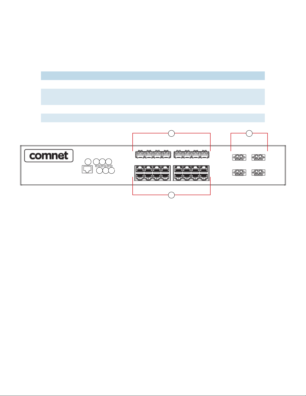
Front Panel
Port Description
SFP Ports 8 × 100/1000BASE-X on SFP port
Bypass Por ts 100 Mbps / 1Gbps / 10 Gbps optical bypass function on two
(duplex) or four (simplex) ports
Copper Ports 16 × 10/100/1000BASE-T(X)
Console Use RS-232 with RJ-45 connector to manage switch.
1 23456
1. Console port
2. Power LED
3. Power 1 LED
4. Power 2 LED
5. Ring master LED
6. Ring status LED
7. Fault indicator
8. 100/1000 Base-X Fiber SFP Ports
9. 10/100/1000 Base-T(X) LAN port
10. Fiber bypass ports
8
7
9
CNGE24MS(M,S)2-OB Front Panel
10
TECH SUPPORT: 1.888.678.9427
INS_CNGE24MS(M,S)2-OB
09/12/12 PAGE 6
Page 7

INSTALLATION AND OPERATION MANUAL CNGE24MS(M,S)2-OB
Front Panel LEDs
LED Color Status Description
PWR Green On DC power module active
PW1 Green On DC power module 1 activated.
PW2 Green On DC Power module 2 activated.
R.M Green On System Operating in Ring Master Mode.
Ring Green On Ring enabled.
Fault Amber On Fault relay. Power failure or Port down/fail.
Gigabit Ethernet ports
LNK /ACT Green Blinking Data transmitted.
On Port is Connected
Full Duplex Amber On Port working under full duplex.
Off Port working in full half duplex mode
Gigabit SFP ports
LNK /ACT Green Blinking Data transmitted.
On Port is Connected
TECH SUPPORT: 1.888.678.9427
INS_CNGE24MS(M,S)2-OB
09/12/12 PAGE 7
Page 8

INSTALLATION AND OPERATION MANUAL CNGE24MS(M,S)2-OB
Rack-mount Installation
The device comes with two mounting kits for you to install the device to a rack. Before installation,
keep the following guidelines in mind.
Elevated Operating Ambient: If installed in a closed environment, make sure the operating
ambient temperature is compatible with the maximum ambient temperature (Tma) specified by
the manufacturer.
Reduced Air Flow: Make sure the amount of air flow required for safe operation of the equipment
is not compromised during installation.
Mechanical Loading: Make sure the mounting of the equipment is not in a hazardous condition
due to uneven mechanical loading.
Circuit Overloading: Consideration should be given to the connection of the equipment to the
supply circuit and the effect that overloading of the circuits might have on overcurrent protection
and supply wiring. Appropriate consideration of equipment nameplate ratings should be used
when addressing this concern.
Follow the steps below to install the device to a rack.
Step 1: Install the L-shape mounting kits provided in the package to the left and right of the
device.
Step 2: With front brackets orientated in front of the rack, mount the device in the rack with four
rack-mounting screws.
TECH SUPPORT: 1.888.678.9427
INS_CNGE24MS(M,S)2-OB
09/12/12 PAGE 8
Page 9

INSTALLATION AND OPERATION MANUAL CNGE24MS(M,S)2-OB
Wiring
WARNING: Do not disconnect modules or wires unless power has been switched off or the area
is known to be non-hazardous. The devices may only be connected to the supply voltage shown
on the type plate.
ATTENTION
1. Be sure to disconnect the power cord before installing and/or wiring your switches.
2. Calculate the maximum possible current in each power wire and common wire. Observe all
electrical codes dictating the maximum current allowable for each wire size.
3. If the current goes above the maximum ratings, the wiring could overheat, causing serious
damage to your equipment.
4. Use separate paths to route wiring for power and devices. If power wiring and device wiring
paths must cross, make sure the wires are perpendicular at the intersection point.
5. Do not run signal or communications wiring and power wiring through the same wire conduit.
To avoid interference, wires with different signal characteristics should be routed separately.
6. You can use the type of signal transmitted through a wire to determine which wires should be
kept separate. The rule of thumb is that wiring sharing similar electrical characteristics can be
bundled together
7. You should separate input wiring from output wiring
8. It is advised to label the wiring to all devices in the system
TECH SUPPORT: 1.888.678.9427
INS_CNGE24MS(M,S)2-OB
09/12/12 PAGE 9
Page 10

INSTALLATION AND OPERATION MANUAL CNGE24MS(M,S)2-OB
Fault Relay
The relay contacts of the 4-pin terminal block connector are used to detect user-configured
events. The two wires attached to the fault contacts form an open circuit when a user-configured
when an event is triggered. If a user-configured event does not occur, the fault circuit remains
closed.
AC Power Connection
For power supply, simply insert the AC power cable to the power connector at the back of the
switch and turn on the power switch. The input voltage is 100V~240V / 50~60Hz.
TECH SUPPORT: 1.888.678.9427
INS_CNGE24MS(M,S)2-OB
09/12/12 PAGE 10
Page 11

INSTALLATION AND OPERATION MANUAL CNGE24MS(M,S)2-OB
Cables
Ethernet Cables
The CNGE24MS(M,S)2-OB switch has standard Ethernet ports. According to the link type, the
switch uses CAT3, CAT4, CAT5 or CAT5-e UTP cables to connect to any other network device (PCs,
servers, switches, routers, or hubs). Please refer to the following table for cable specifications.
Cable Type Max. Length Connector
10BASE-T CAT3, CAT4, CAT5 100Ω UTP 100m (328ft) RJ-45
100BASE-T X CAT5 100Ω UTP UTP 100m (328ft) RJ-45
1000BASE-TX CAT5/CAT5-e 100Ω UTP UTP 100m (328ft) RJ-45
Cable Types and Specifications
10/100BASE-T(X) Pin Assignments
With 10/100BASE-T(X) cable, pins 1 and 2 are used for transmitting data, and pins 3 and 6 are
used for receiving data.
Pin Number Assignment
1 TD+
2 TD-
3 RD+
4 Not used
5 Not used
6 RD-
7 Not used
8 Not used
10/100 BASE-T RJ-45 Pin Assignments
TECH SUPPORT: 1.888.678.9427
INS_CNGE24MS(M,S)2-OB
09/12/12 PAGE 11
Page 12

INSTALLATION AND OPERATION MANUAL CNGE24MS(M,S)2-OB
Pin Number Assignment
1 BI_DA+
2 BI_DA-
3 BI_DB+
4 BI _DC+
5 BI_DC-
6 BI_DB-
7 BI_DD+
8 BI_DD-
1000 BASE-T RJ-45 Pin Assignments
The CNGE24MS(M,S)2-OB switch supports auto MDI/MDI-X operation. You can use a straightthrough cable to connect a PC to the switch. The table below shows the 10/100BASE-T(X) MDI and
MDI-X port pin outs.
Pin Number MDI port MDI-X port
1 TD+(transmit) RD+(receive)
2 TD-(transmit) RD - (receive)
3 RD+(receive) TD+(transmit)
4 Not used Not used
5 Not used Not used
6 RD - (receive) TD-(transmit)
7 Not used Not used
8 Not used Not used
10/100 BASE-T MDI/MDI-X pins assignment
Pin Number MDI port MDI-X port
1 BI_DA+ BI_DB+
2 BI_DA- BI_DB-
3 BI_DB+ BI _DA+
4 BI _DC+ BI_DD+
5 BI_DC- BI_DD-
6 BI_DB- BI_DA-
7 BI_DD+ BI _DC+
8 BI_DD- BI_DC-
1000 BASE-T MDI/MDI-X pins assignment
Note: “+” and “-” signs represent the polarity of the wires that make up each wire pair.
TECH SUPPORT: 1.888.678.9427
INS_CNGE24MS(M,S)2-OB
09/12/12 PAGE 12
Page 13
INSTALLATION AND OPERATION MANUAL CNGE24MS(M,S)2-OB
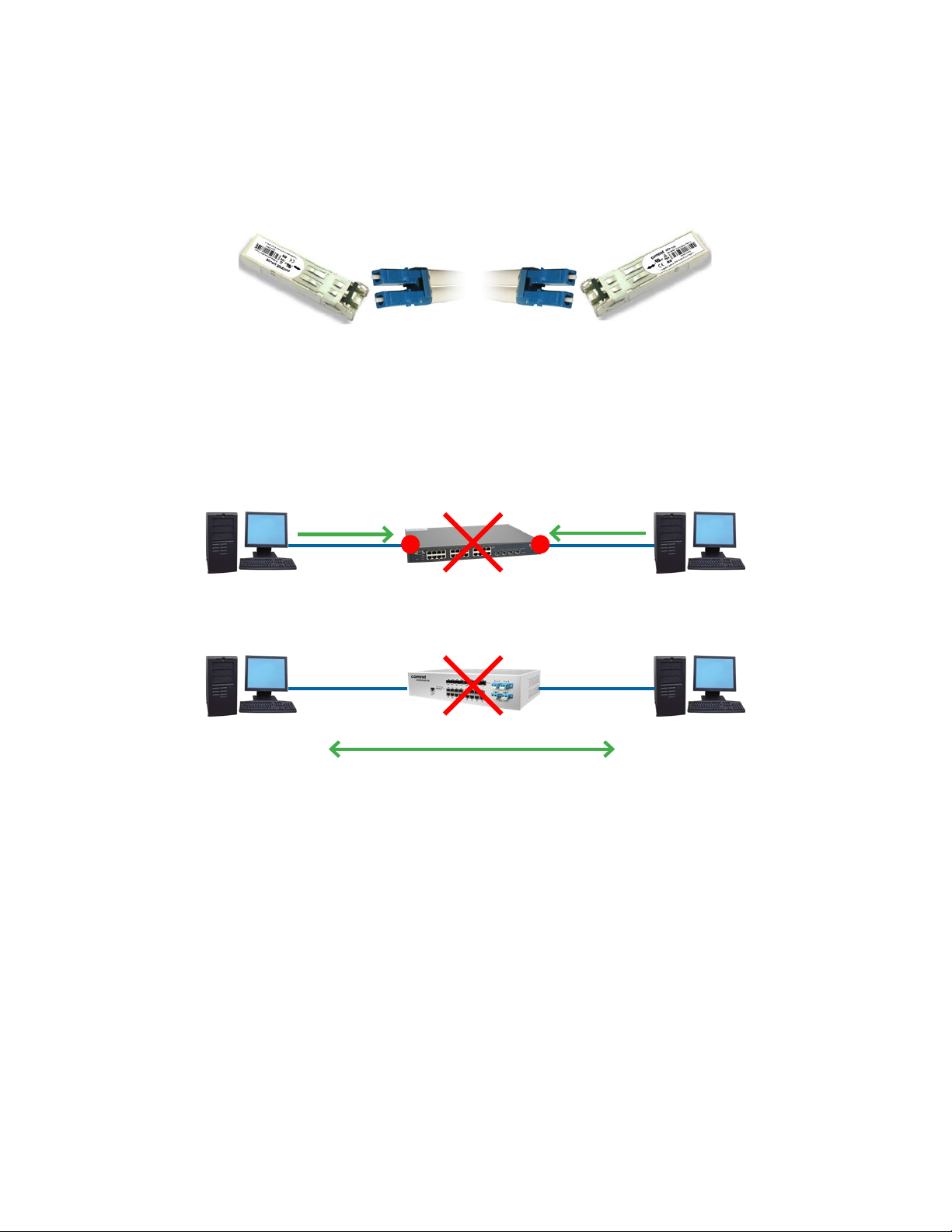
SFP
The switch has fiber optic ports with SFP connectors. The fiber optical ports are available with
multi-mode and single-mode fiber with various distance and connector types. Please remember
that the TX port of Switch A should be connected to the RX port of Switch B.
Switch-A Switch-B
Bypass Ports
When a device connected to other devices through a switch without bypass function, the device
will lose connection if the switch loses power as traffic will not be able to flow through the link (as
shown in the figure below).
Packet Packet
PC1 Other Switch PC2
! !
Switches with bypass functions provide one or more sets of bypass ports that ensure constant
network connectivity during power failure.
Packet
PC1 ComNet Bypass Switch PC2
PC1 Packet Bypass to PC2
The CNGE24MS(M,S)2-OB provides two sets of bypass fiber ports, giving the SFP fiber ports
addition redundancy capabilities. Connect a LC fiber cable from a fiber port to a monitor port
on the front panel and another LC fiber cable from the corresponding network port to another
switch.
When the switch breaks down, incoming traffic will travel through the bypass port board and onto
another active switch.
Note that the fiber port will still work if it is not connected to any monitor port. However, the fiber
port will not have bypass ability when the device is down.
TECH SUPPORT: 1.888.678.9427
INS_CNGE24MS(M,S)2-OB
09/12/12 PAGE 13
Page 14

INSTALLATION AND OPERATION MANUAL CNGE24MS(M,S)2-OB
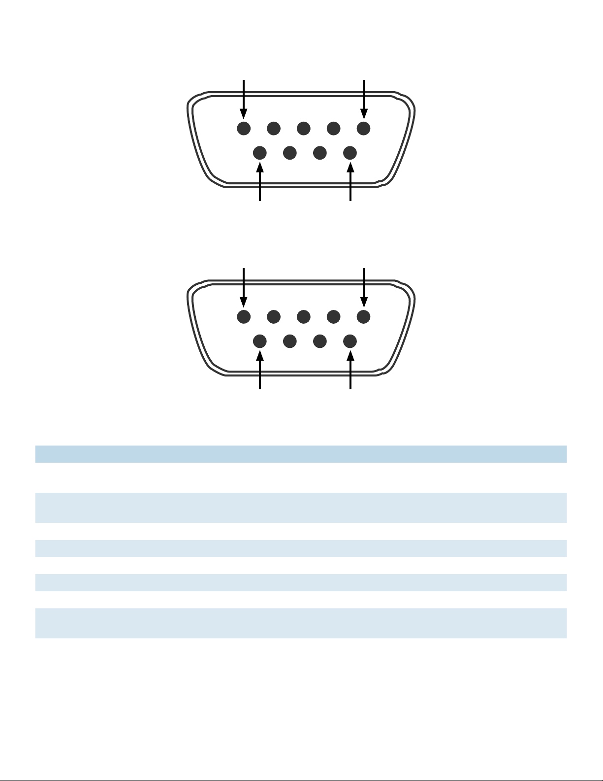
Console Cable
The CNGE24MS(M,S)2-OB switch can be managed by the console port. The DB-9 to RJ-45 cable
can be found in the package. You can connect them to the PC via a RS-232 cable with DB-9 female
connector and the other end (RJ-45 connector) connects to console port of the switch.
PC pin
out (male)
assignment
RS-232 with
DB9 female
connector
DB9 to RJ 45
Pin #2 RD Pin #2 TD Pin #2
Pin #3 TD Pin #3 RD Pin #3
Pin #5 GD Pin #5 GD Pin #5
TECH SUPPORT: 1.888.678.9427
INS_CNGE24MS(M,S)2-OB
09/12/12 PAGE 14
Page 15
INSTALLATION AND OPERATION MANUAL CNGE24MS(M,S)2-OB
5
9
DB9 Male
1
1
6
5
6
DB9 Female
9
Pin Male Connector Female Connector
1 Received Line Signal Detect (Received by DTE
Device)
Received Line Signal Detect (Transmitted
from DCE Device)
2 Received Data (Received by DTE Device) Transmitted Data (Transmitted from DCE
Device)
3 Transmitted Data (Transmitted from DTE Device) Received Data (Received by DCE Device)
4 DTE Ready (Transmitted from DTE Device) DTE Ready (Received by DCE Device)
5 Signal Ground Signal Ground
6 DCE Ready (Received by DTE Device) DCE Ready (Transmitted from DCE Device)
7 Request to Send (Transmitted from DTE Device) Clear to Send (Received by DCE Device)
8 Clear to Send (Received by DTE Device) Request to Send (Transmitted from DCE
Device)
9 Ring Indicator (Received by DTE Device) Ring Indicator (Transmitted from DCE Device)
TECH SUPPORT: 1.888.678.9427
INS_CNGE24MS(M,S)2-OB
09/12/12 PAGE 15
Page 16
INSTALLATION AND OPERATION MANUAL CNGE24MS(M,S)2-OB
WEB Management
Attention: While installing and upgrading firmware, please remove physical loop connection first.
DO NOT power off equipment while the firmware is upgrading!
Configuration by Web Browser
This section details configuration through the Web browser.
About Web-based Management
An embedded HTML web site resides in the flash memory on the CPU board. It contains
advanced management features and allows you to manage the switch from anywhere on the
network through a standard web browser such as Microsoft Internet Explorer.
The Web-Based Management function supports Internet Explorer 5.0 or later. It is based on Java
Applets with an aim to reduce network bandwidth consumption, enhance access speed and
present an easy viewing screen.
Note: By default, IE5.0 or later version does not allow Java Applets to open sockets. You need to
explicitly modify the browser setting in order to enable Java Applets to use network ports.
Preparing for Web Management
The default value is as below:
IP Address: 192.168 .10.1
Subnet Mask: 255.255.255.0
Default Gateway: 192 .168 .10. 254
User Name: admin
Password: admin
System Login
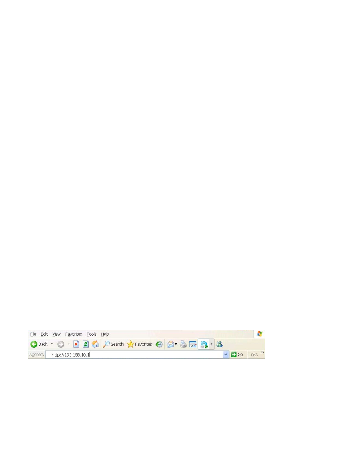
1. Launch Internet Explorer.
2. Type ht t p://19 2 .16 8 .10 .1. Press Enter.
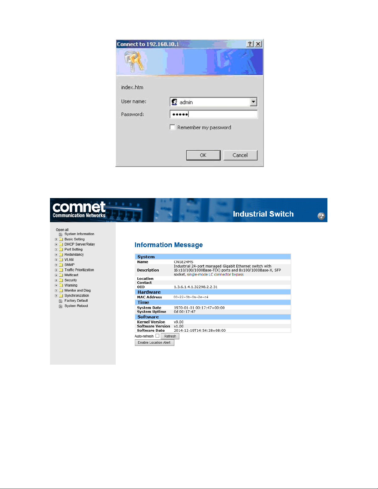
3. The login screen appears.
4. Key in the username and password. The default username and password is admin.
5. Select Enter or OK button, then the main interface of the Web-based management appears.
INS_CNGE24MS(M,S)2-OB
TECH SUPPORT: 1.888.678.9427
09/12/12 PAGE 16
Page 17
INSTALLATION AND OPERATION MANUAL CNGE24MS(M,S)2-OB
Login screen
Main Interface
TECH SUPPORT: 1.888.678.9427
Main interface
INS_CNGE24MS(M,S)2-OB
09/12/12 PAGE 17
Page 18
INSTALLATION AND OPERATION MANUAL CNGE24MS(M,S)2-OB
Basic Setting
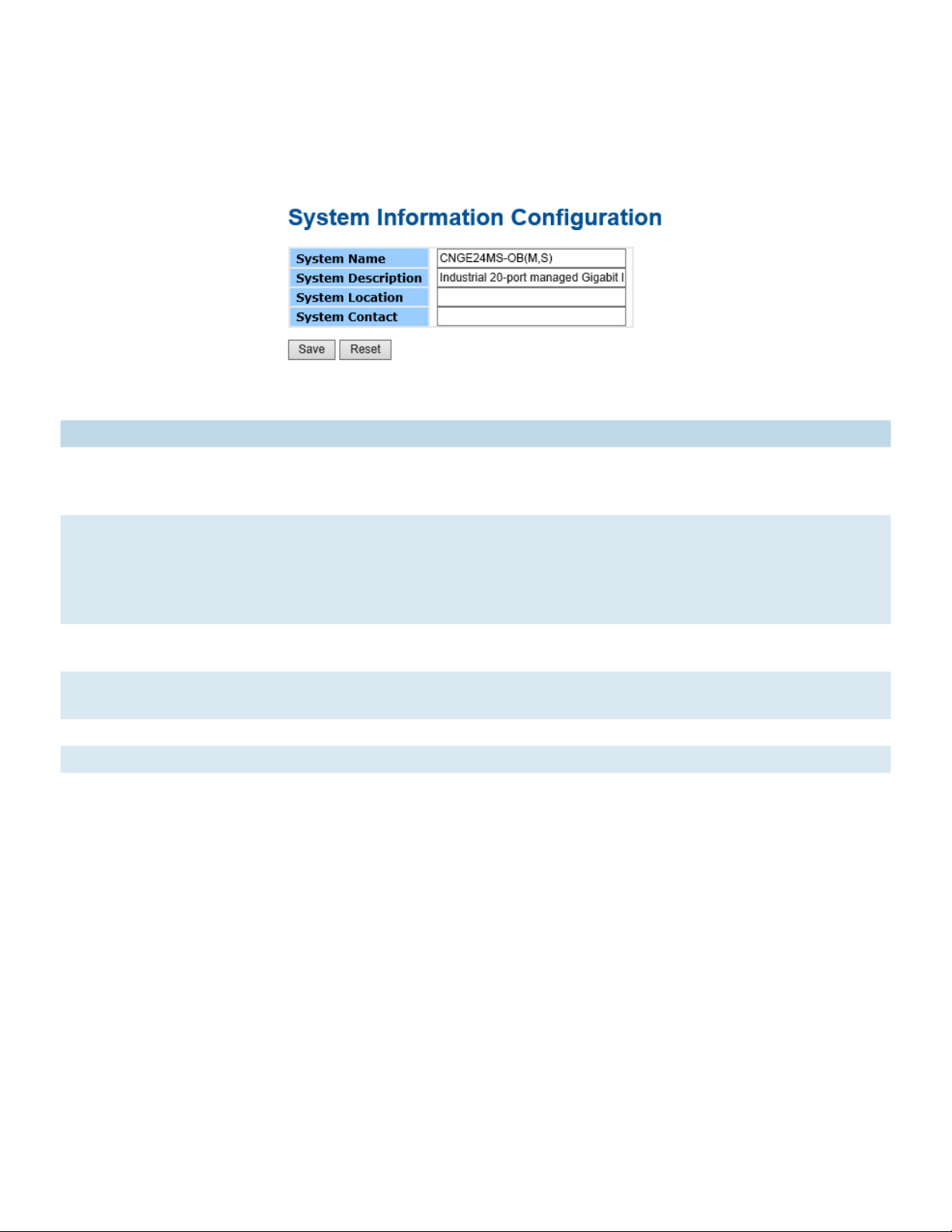
System Information
The switch system information is provided here.
System Information interface
Label Description
System Contact The textual identification of the contact person for this managed node, together with
information on how to contact this person. The allowed string length is 0 to 255, and
the allowed content is the ASCII characters from 32 to 126.
System Name An administratively assigned name for this managed node. By convention, this is the
node’s fully-qualified domain name. A domain name is a text string drawn from the
alphabet (A-Z, a-z), digits (0-9), minus sign (-). No space characters are permitted as
part of a name. The first character must be an alpha character. And the first or last
character must not be a minus sign. The allowed string length is 0 to 255.
System Location The physical location of this node(e.g., telephone closet, 3rd floor). The allowed string
length is 0 to 255, and the allowed content is the ASCII characters from 32 to 126.
System
Description
The description of this switch. The allowed string length is 0 to 255, and the allowed
content is the ASCII characters from 32 to 126.
Save Select to save changes.
Reset Select to undo any changes made locally and revert to previously saved values.
TECH SUPPORT: 1.888.678.9427
INS_CNGE24MS(M,S)2-OB
09/12/12 PAGE 18
Page 19
INSTALLATION AND OPERATION MANUAL CNGE24MS(M,S)2-OB
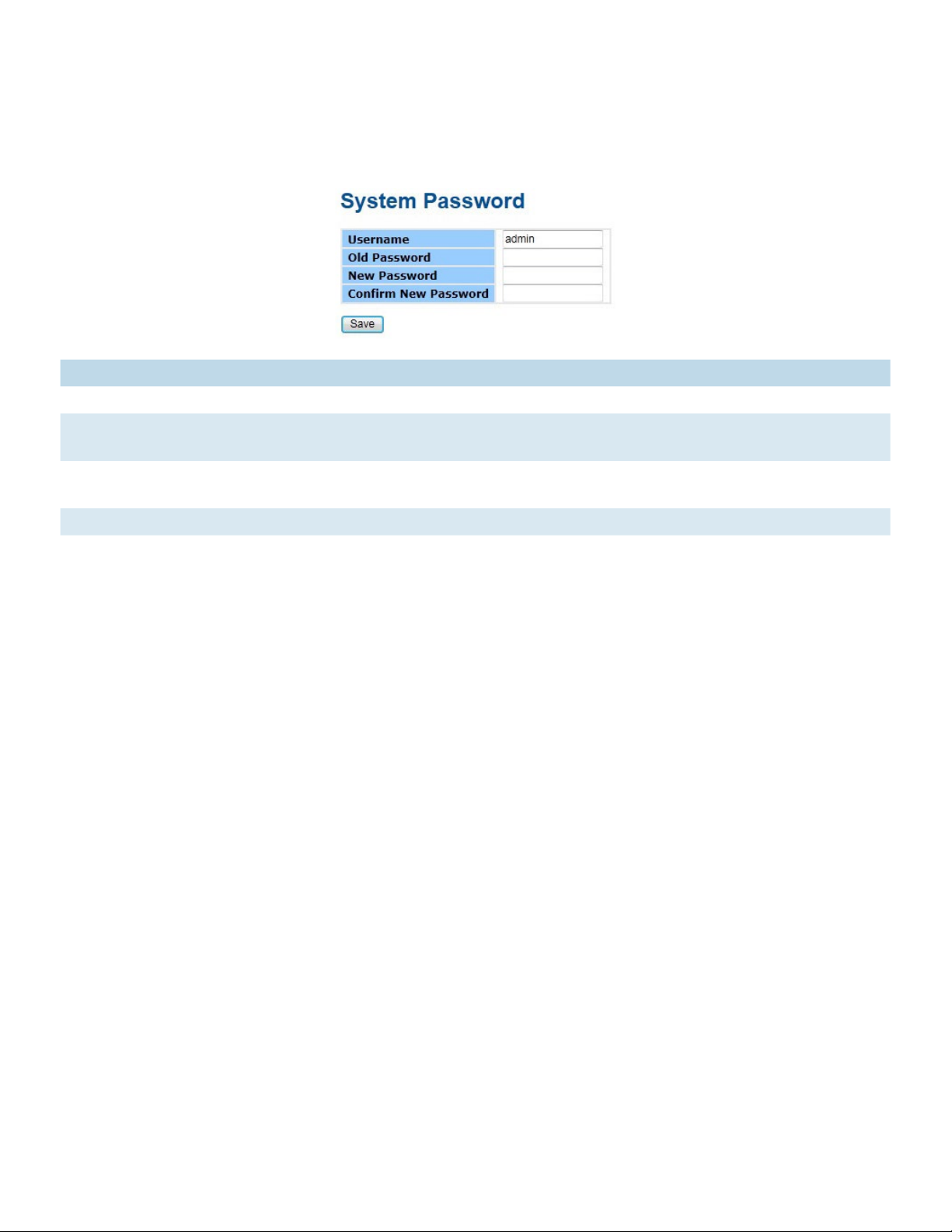
Admin & Password
This page allows you to configure the system password required to access the web pages or log
in from the CLI.
Label Description
Old Password Enter the current system password. If this is incorrect, the new password will not be set.
New Password The system password. The allowed string length is 0 to 31, and the allowed content is
the ASCII characters from 32 to 126.
Confirm New
Re-type the new password.
password
Save Select to save changes.
TECH SUPPORT: 1.888.678.9427
INS_CNGE24MS(M,S)2-OB
09/12/12 PAGE 19
Page 20
INSTALLATION AND OPERATION MANUAL CNGE24MS(M,S)2-OB
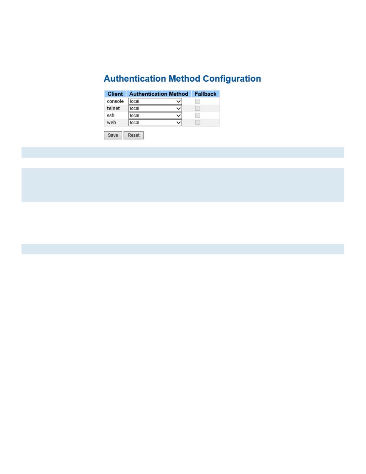
Authentication Method
This page allows you to configure how a user is authenticated when he logs into the switch via one
of the management client interfaces.
Label Description
Client The management client for which the configuration below applies.
Authentication
Method
Authentication Method can be set to one of the following values:
none: authentication is disabled and login is not possible.
local: use the local user database on the switch for authentication.
radius: use a remote RADIUS server for authentication.
Fallback Enable fallback to local authentication by checking this box.
If none of the configured authentication servers are alive, the local user database is used
for authentication.
This is only possible if the Authentication Method is set to a value other than ‘none’ or
‘local’.
Save Click to save changes.
Reset Click to undo any changes made locally and revert to previously saved values.
TECH SUPPORT: 1.888.678.9427
INS_CNGE24MS(M,S)2-OB
09/12/12 PAGE 20
Page 21
INSTALLATION AND OPERATION MANUAL CNGE24MS(M,S)2-OB
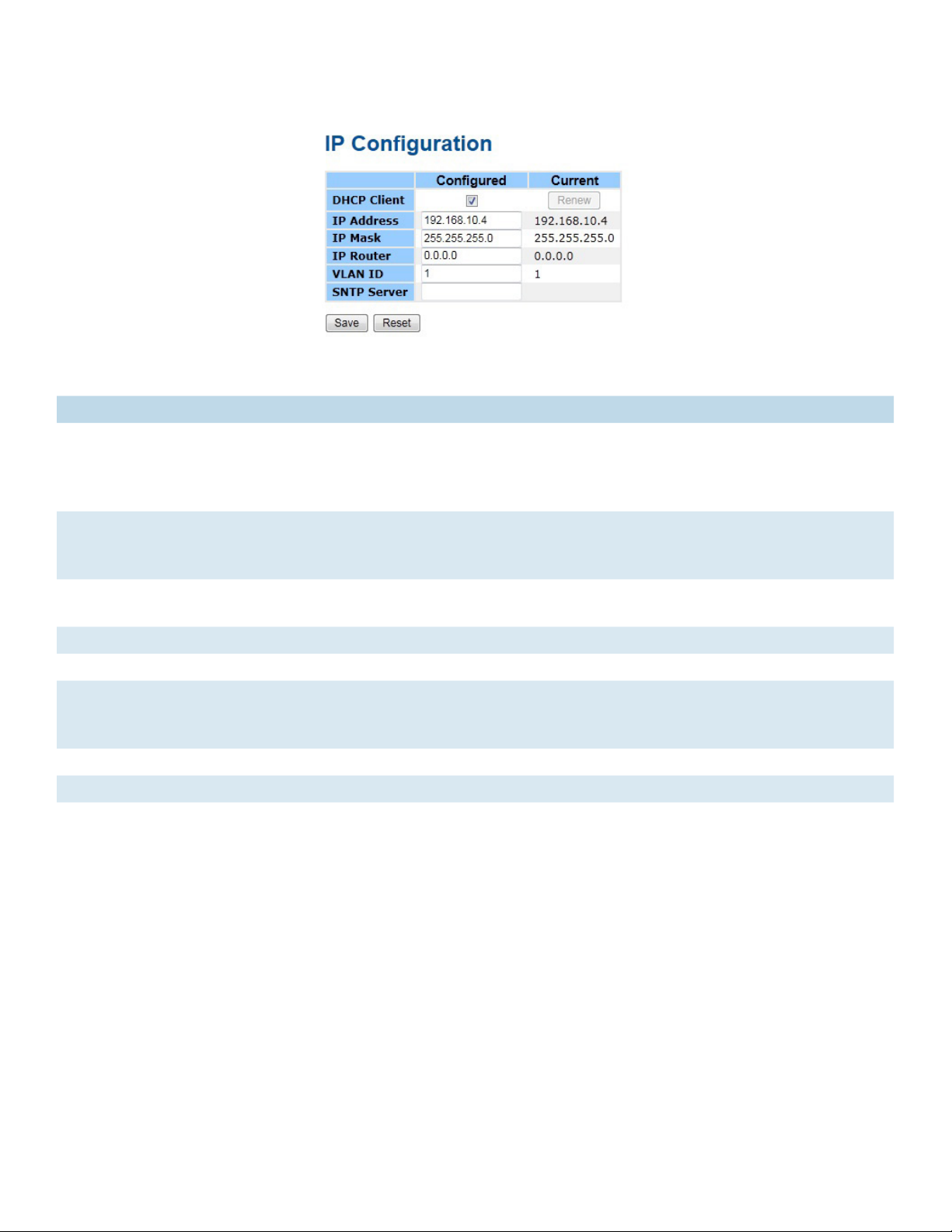
IP Setting
Configure the managed switch IP information on this page.
Label Description
DHCP Client Enable the DHCP client by checking this box. If DHCP fails and the configured IP
address is zero, DHCP will retry. If DHCP fails and the configured IP address is nonzero, DHCP will stop and the configured IP settings will be used. The DHCP client will
announce the configured System Name as hostname to provide DNS lookup.
IP Address Assign the IP address that the network is using. If DHCP client function is enabling,
you do not need to assign the IP address. The network DHCP server will assign the IP
address for the switch and it will be display in this column. The default IP is 192.168.10.1
IP Mask Assign the subnet mask of the IP address. If DHCP client function is enabling, you do
not need to assign the subnet mask
IP Router Assign the network gateway for the switch. The default gateway is 192.168.10.254
VLAN ID Provide the managed VLAN ID. The allowed range is 1 through 4095.
SNTP Server SNTP is an acronym for Simple Network Time Protocol, a network protocol for
synchronizing the clocks of computer systems. SNTP uses UDP (datagrams) as transport
layer.
Save Select to save changes.
Reset Select to undo any changes made locally and revert to previously saved values.
Renew Select to renew DHCP. This button is only available if DHCP is enabled.
TECH SUPPORT: 1.888.678.9427
INS_CNGE24MS(M,S)2-OB
09/12/12 PAGE 21
Page 22
INSTALLATION AND OPERATION MANUAL CNGE24MS(M,S)2-OB
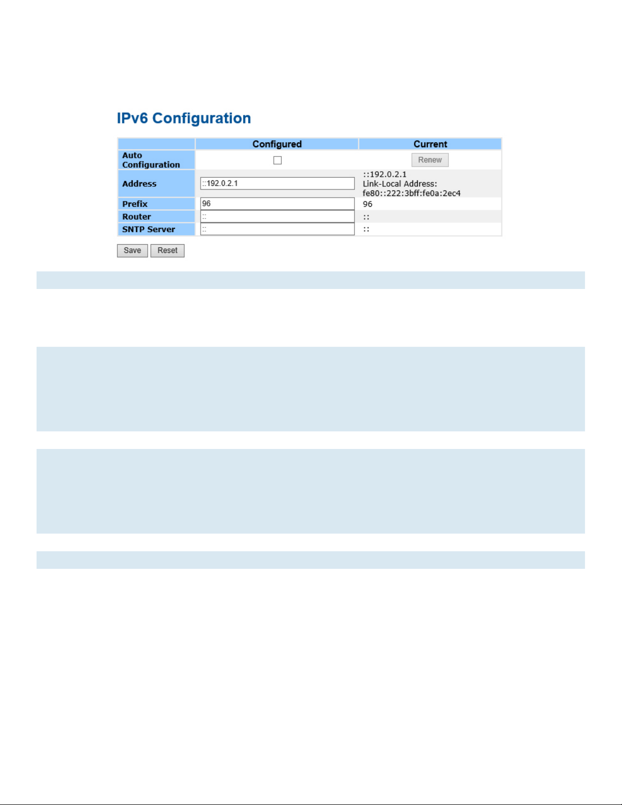
IPv6 Setting
Configure the switch-management IPv6 information on this page.
Label Description
Auto
Configuration
Enable IPv6 auto-configuration by checking this box. If the system cannot obtain the
stateless address in time, the configured IPv6 settings will be used. The router may delay
responding to a router solicitation for a few seconds, the total time needed to complete
auto-configuration can be significantly longer.
Address Provide the IPv6 address of this switch. IPv6 address is in 128-bit records represented
as eight fields of up to four hexadecimal digits with a colon separating each field (:). For
example, ‘fe80::215:c5ff:fe03:4dc7’. The symbol ‘::’ is a special syntax that can be used
as a shorthand way of representing multiple 16-bit groups of contiguous zeros; but it
can appear only once. It can also represent a legally valid IPv4 address. For example,
‘::192.1.2.34’.
Prefix Provide the IPv6 Prefix of this switch. The allowed range is 1 to 128.
Router Provide the IPv6 gateway address of this switch. IPv6 address is in 128-bit records
represented as eight fields of up to four hexadecimal digits with a colon separating each
field (:). For example, ‘fe80::215:c5ff:fe03:4dc7’. The symbol ‘::’ is a special syntax that
can be used as a shorthand way of representing multiple 16-bit groups of contiguous
zeros; but it can appear only once. It can also represent a legally valid IPv4 address. . For
example, ‘::192.1.2.34’.
Save Click to save changes.
Reset Click to undo any changes made locally and revert to previously saved values.
TECH SUPPORT: 1.888.678.9427
INS_CNGE24MS(M,S)2-OB
09/12/12 PAGE 22
Page 23
INSTALLATION AND OPERATION MANUAL CNGE24MS(M,S)2-OB
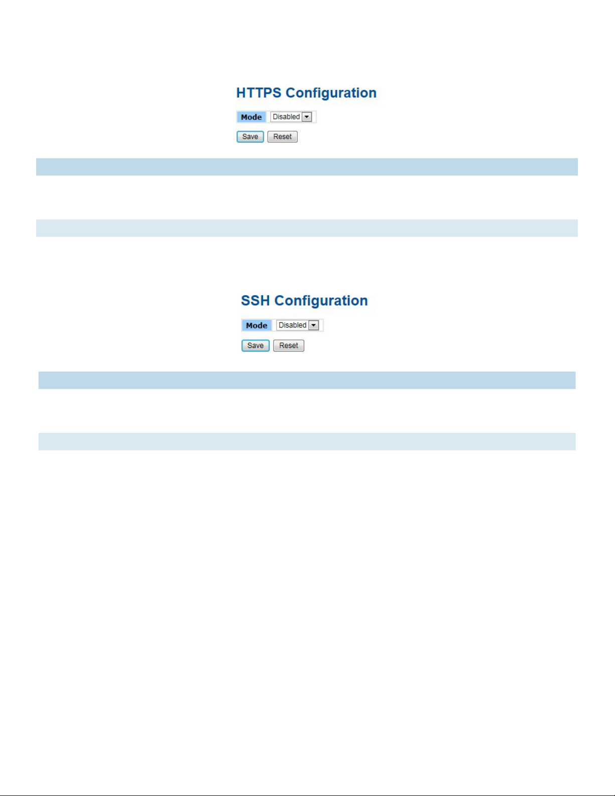
HTTPS
Label Description
Mode Indicates the HTTPS mode operation. Possible modes are:
Enabled: Enable HTTPS mode operation.
Disabled: Disable HTTPS mode operation.
Save Select to save changes.
Reset Select to undo any changes made locally and revert to previously saved values.
SSH
Label Description
Mode Indicates the SSH mode operation. Possible modes are:
Enabled: Enable SSH mode operation.
Disabled: Disable SSH mode operation.
Save Select to save changes.
Reset Select to undo any changes made locally and revert to previously saved values.
TECH SUPPORT: 1.888.678.9427
INS_CNGE24MS(M,S)2-OB
09/12/12 PAGE 23
Page 24
INSTALLATION AND OPERATION MANUAL CNGE24MS(M,S)2-OB
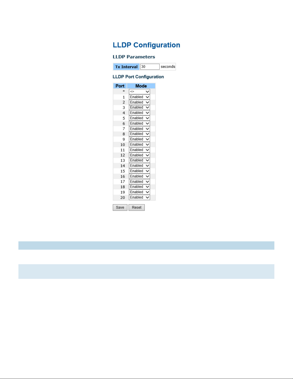
LLDP
LLDP Parameters
This page allows the user to inspect and configure the current LLDP port settings.
Label Description
Enabled The switch will send out LLDP information, and will analyze LLDP information received
from neighbors.
Disabled The switch will not send out LLDP information, and will drop LLDP information received
from neighbors.
INS_CNGE24MS(M,S)2-OB
TECH SUPPORT: 1.888.678.9427
09/12/12 PAGE 24
Page 25

INSTALLATION AND OPERATION MANUAL CNGE24MS(M,S)2-OB
LLDP Neighbor Information
This page provides a status overview for all LLDP neighbors. The displayed table contains a row
for each port on which an LLDP neighbor is detected. The columns hold the following information:
Label Description
Local Port The port on which the LLDP frame was received.
Chassis ID The Chassis ID is the identification of the neighbor’s LLDP frames.
Remote Port ID The Remote Port ID is the identification of the neighbor port.
System Name System Name is the name advertised by the neighbor unit.
Port Description Port Description is the port description advertised by the neighbor unit.
System
Capabilities
System Capabilities describes the neighbor unit’s capabilities. The possible capabilities
are:
1. Other
2. Repeater
3. Bridge
4. WLAN Access Point
5. Router
6. Telephone
7. DOCSIS cable device
8. Station only
9. Reserved
When a capability is enabled, the capability is followed by (+). If the capability is
disabled, the capability is followed by (-).
Management
Address
Management Address is the neighbor unit’s address that is used for higher layer entities
to assist the discovery by the network management. This could for instance hold the
neighbor’s IP address.
Refresh Select to refresh the page immediately.
Auto-Refresh Check this box to enable an automatic refresh of the page at regular intervals.
TECH SUPPORT: 1.888.678.9427
INS_CNGE24MS(M,S)2-OB
09/12/12 PAGE 25
Page 26

INSTALLATION AND OPERATION MANUAL CNGE24MS(M,S)2-OB
LLDP Statistics
This page provides an overview of all LLDP traffic.
Two types of counters are shown. Global counters are counters that refer to the whole stack,
switch, while local counters refer to counters for the currently selected switch.
Global Counters
Label Description
Neighbor
entries were last
changed at
Total Neighbors
Entries Added
Total Neighbors
Entries Deleted
Total Neighbors
Entries Dropped
Total Neighbors
Entries Aged Out
Shows the time for when the last entry was last deleted or added. It is also shows the
time elapsed since last change was detected.
Shows the number of new entries added since switch reboot.
Shows the number of new entries deleted since switch reboot.
Shows the number of LLDP frames dropped due to that the entry table was full.
Shows the number of entries deleted due to Time-To-Live expiring.
TECH SUPPORT: 1.888.678.9427
INS_CNGE24MS(M,S)2-OB
09/12/12 PAGE 26
Page 27
INSTALLATION AND OPERATION MANUAL CNGE24MS(M,S)2-OB
Local Counters
Label Description
Local Port The port on which LLDP frames are received or transmitted.
Tx Fr ames The number of LLDP frames transmitted on the port.
Rx Frames The number of LLDP frames received on the port.
Rx Errors The number of received LLDP frames containing some kind of error.
Frames DiscardedIf an LLDP frame is received on a port, and the switch’s internal table has run full, the
LLDP frame is counted and discarded. This situation is known as “Too Many Neighbors”
in the LLDP standard. LLDP frames require a new entry in the table when the Chassis ID
or Remote Port ID is not already contained within the table. Entries are removed from
the table when a given port links down, an LLDP shutdown frame is received, or when
the entry ages out.
TLVs Discarded Each LLDP frame can contain multiple pieces of information, known as TLVs (TLV is short
for “Type Length Value”). If a TLV is malformed, it is counted and discarded.
TLVs
The number of well-formed TLVs, but with an unknown type value.
Unrecognized
Org. Discarded The number of organizationally TLVs received.
Age-Outs Each LLDP frame contains information about how long time the LLDP information is
valid (age-out time). If no new LLDP frame is received within the age out time, the LLDP
information is removed, and the Age-Out counter is incremented.
Refresh Select to refresh the page immediately.
Clear Clears the local counters. All counters (including global counters) are cleared upon
reboot.
Auto-Refresh Check this box to enable an automatic refresh of the page at regular intervals.
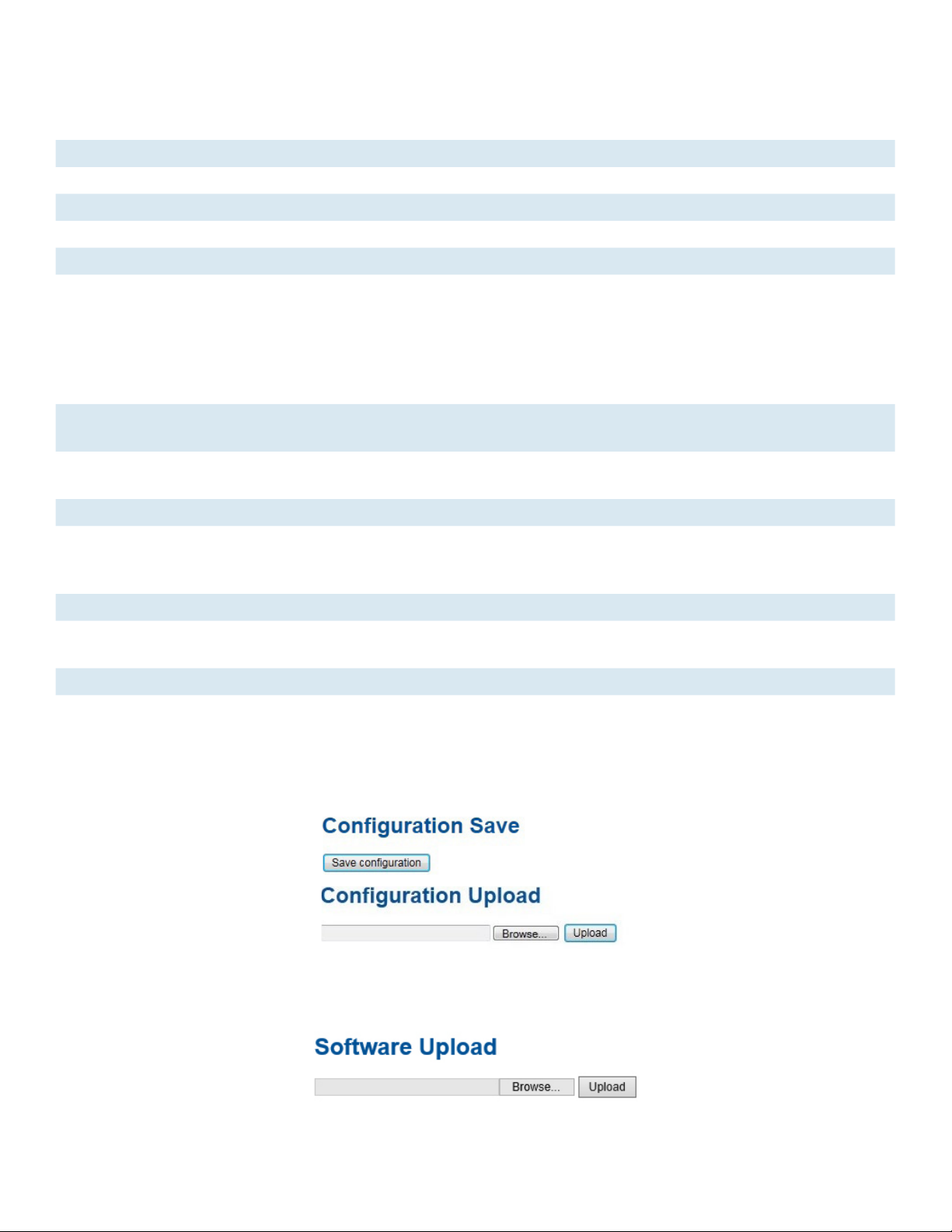
Backup/Restore Configuration
You can save/view or load the switch configuration. The configuration file is in XML format with a
hierarchy of tags:
Firmware Update
This page facilitates an update of the firmware controlling the switch.
TECH SUPPORT: 1.888.678.9427
INS_CNGE24MS(M,S)2-OB
09/12/12 PAGE 27
Page 28
INSTALLATION AND OPERATION MANUAL CNGE24MS(M,S)2-OB
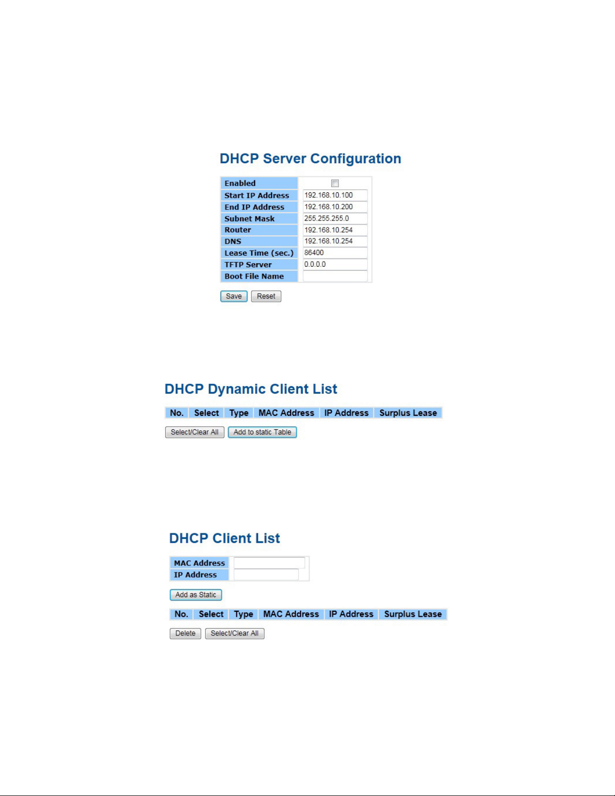
DHCP Server
Setting
The system provides with DHCP server function. Enable the DHCP server function, the switch
system will be a DHCP server.
DHCP Dynamic Client List
When the DHCP server function is activated, the system will collect the DHCP client information
and display in here.
DHCP Client List
You can assign the specific IP address which is in the assigned dynamic IP range to the specific
port. When the device is connecting to the port and asks for dynamic IP assigning, the system will
assign the IP address that has been assigned before in the connected device.
TECH SUPPORT: 1.888.678.9427
INS_CNGE24MS(M,S)2-OB
09/12/12 PAGE 28
Page 29
INSTALLATION AND OPERATION MANUAL CNGE24MS(M,S)2-OB
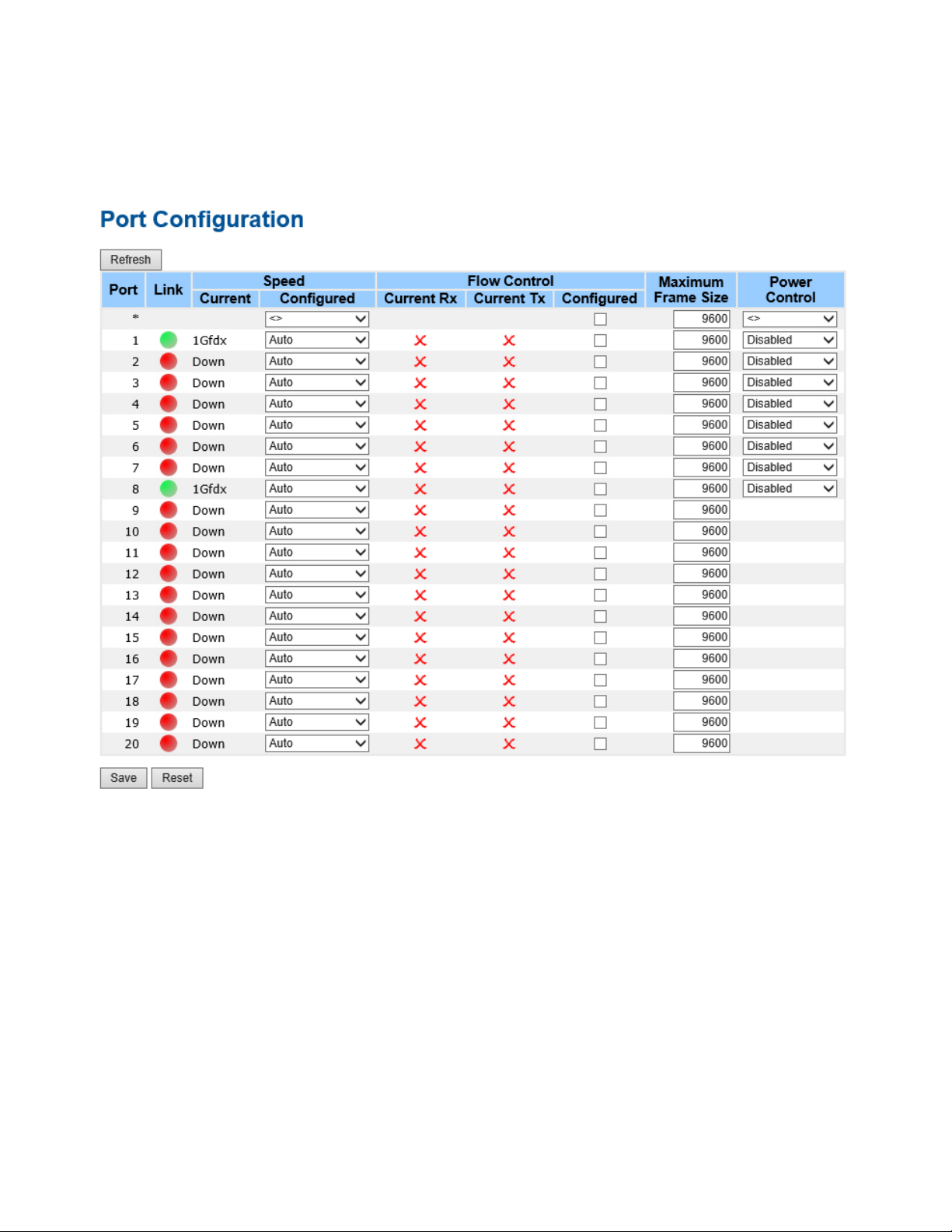
Port Setting
Port Control
This page displays current port configurations. Ports can also be configured here.
TECH SUPPORT: 1.888.678.9427
INS_CNGE24MS(M,S)2-OB
09/12/12 PAGE 29
Page 30

INSTALLATION AND OPERATION MANUAL CNGE24MS(M,S)2-OB
Label Description
Port This is the logical port number for this row.
Link The current link state is displayed graphically. Green indicates the link is up and red that
it is down.
Current Link
Provides the current link speed of the port.
Speed
Configured Link
Speed
Select any available link speed for the given switch port.
Auto Speed selects the highest speed that is compatible with a link partner.
Disabled disables the switch port operation.
Flow Control When Auto Speed is selected for a port, this section indicates the flow control
capability that is advertised to the link partner.
When a fixed-speed setting is selected, that is what is used. The Current Rx column
indicates whether pause frames on the port are obeyed, and the Current Tx column
indicates whether pause frames on the port are transmitted. The Rx and Tx settings are
determined by the result of the last Auto-Negotiation.
Check the configured column to use flow control. This setting is related to the setting
for Configured Link Speed.
Maximum Frame Enter the maximum frame size allowed for the switch port, including FCS. The allowed
range is 1518 bytes to 9600 bytes.
Power Control Allows for changing the power savings mode parameters per port.
Disabled: All power savings mechanisms disabled.
ActiPHY: Link down power savings enabled.
PerfectReach: Link up power savings enabled.
Enabled: Both link up and link down power savings enabled.
Save Select to save changes.
Reset Select to undo any changes made locally and revert to previously saved values.
Refresh Select to refresh the page. Any changes made locally will be undone.
TECH SUPPORT: 1.888.678.9427
INS_CNGE24MS(M,S)2-OB
09/12/12 PAGE 30
Page 31

INSTALLATION AND OPERATION MANUAL CNGE24MS(M,S)2-OB
Port Trunk
Trunk Configuration
This page is used to configure the Aggregation hash mode and the aggregation group.
Label Description
Source MAC
Address
The Source MAC address can be used to calculate the destination port for the frame.
Check to enable the use of the Source MAC address, or uncheck to disable. By default,
Source MAC Address is enabled.
Destination MAC
Address
The Destination MAC Address can be used to calculate the destination port for the
frame. Check to enable the use of the Destination MAC Address, or uncheck to disable.
By default, Destination MAC Address is disabled.
IP Address The IP address can be used to calculate the destination port for the frame. Check
to enable the use of the IP Address, or uncheck to disable. By default, IP Address is
enabled.
TCP/UDP Port
Number
The TCP/UDP port number can be used to calculate the destination port for the frame.
Check to enable the use of the TCP/UDP Port Number, or uncheck to disable. By
default, TCP/UDP Port Number is enabled.
Label Description
Group ID Indicates the group ID for the settings contained in the same row. Group ID “Normal”
indicates there is no aggregation. Only one group ID is valid per port.
Port Members Each switch port is listed for each group ID. Select a radio button to include a port in
an aggregation, or clear the radio button to remove the port from the aggregation. By
default, no ports belong to any aggregation group. Only full duplex ports can join an
aggregation and ports must be in the same speed in each group.
INS_CNGE24MS(M,S)2-OB
TECH SUPPORT: 1.888.678.9427
09/12/12 PAGE 31
Page 32

INSTALLATION AND OPERATION MANUAL CNGE24MS(M,S)2-OB
LACP Port Configuration
This page allows the user to inspect the current LACP port configurations, and possibly change
them as well.
Label Description
Port Indicates the group ID for the settings contained in the same row. Group ID “Normal”
indicates there is no aggregation. Only one group ID is valid per port.
LACP Enabled Each switch port is listed for each group ID. Select a radio button to include a port in
an aggregation, or clear the radio button to remove the port from the aggregation. By
default, no ports belong to any aggregation group. Only full duplex ports can join an
aggregation and ports must be in the same speed in each group.
Key The Key value incurred by the port, range 1-65535. The Auto setting will set the key
as appropriate by the physical link speed, 10Mb = 1, 100Mb = 2, 1Gb = 3. Using the
Specific setting, a user-defined value can be entered. Ports with the same Key value can
participate in the same aggregation group, while ports with different keys cannot.
Role The Role shows the LACP activity status. Active will transmit LACP packets each second,
while Passive will wait for a LACP packet from a partner (speak if spoken to).
Save Select to save changes.
Reset Select to undo any changes made locally and revert to previously saved values.
INS_CNGE24MS(M,S)2-OB
TECH SUPPORT: 1.888.678.9427
09/12/12 PAGE 32
Page 33

INSTALLATION AND OPERATION MANUAL CNGE24MS(M,S)2-OB
LACP System Status
This page provides a status overview for all LACP instances.
Label Description
Aggr ID The Aggregation ID associated with this aggregation instance. For LLAG the id is shown
as ‘isid:aggr-id’ and for GLAGs as ‘aggr-id’
Partner
The system ID (MAC address) of the aggregation partner.
System ID
Partner Key The Key that the partner has assigned to this aggregation ID.
Last Changed The time since this aggregation changed.
Local Ports Shows which ports are a part of this aggregation for this switch/stack. The format is:
“Switch ID:Port”.
Refresh Select to refresh the page immediately.
Auto-Refresh Check this box to enable an automatic refresh of the page at regular intervals.
TECH SUPPORT: 1.888.678.9427
INS_CNGE24MS(M,S)2-OB
09/12/12 PAGE 33
Page 34

INSTALLATION AND OPERATION MANUAL CNGE24MS(M,S)2-OB
LACP Status
This page provides a status overview for LACP status for all ports.
Label Description
Port The switch port number.
LACP ‘Yes’ means that LACP is enabled and the port link is up. ‘No’ means that LACP is not
enabled or that the port link is down. ‘Backup’ means that the port could not join
the aggregation group but will join if other port leaves. Meanwhile it’s LACP status is
disabled.
Key The key assigned to this port. Only ports with the same key can aggregate together.
Aggr ID The Aggregation ID assigned to this aggregation group.
Partner System ID The partners System ID (MAC address).
Partner Port The partners port number connected to this port.
Refresh Select to refresh the page immediately.
Auto-Refresh Check this box to enable an automatic refresh of the page at regular intervals.
TECH SUPPORT: 1.888.678.9427
INS_CNGE24MS(M,S)2-OB
09/12/12 PAGE 34
Page 35

INSTALLATION AND OPERATION MANUAL CNGE24MS(M,S)2-OB
LACP Statistics
This page provides an overview for LACP statistics for all ports.
Label Description
Port The switch port number
LACP TransmittedShows how many LACP frames have been sent from each port
LACP Received Shows how many LACP frames have been received at each port.
Discarded Shows how many unknown or illegal LACP frames have been discarded at each port.
Refresh Select to refresh the page immediately.
Auto-Refresh Check this box to enable an automatic refresh of the page at regular intervals.
Clear Clears the counters for all ports
TECH SUPPORT: 1.888.678.9427
INS_CNGE24MS(M,S)2-OB
09/12/12 PAGE 35
Page 36

INSTALLATION AND OPERATION MANUAL CNGE24MS(M,S)2-OB
Redundancy
C-Ring
C-Ring is the most powerful Ring in the world. The recovery time of C-Ring is less than 30ms. It
can reduce unexpected damage caused by network topology change. C-Ring Supports 3 Ring
topologies: C-Ring, Coupling Ring and Dual Homing.
Ring interface
Label Description
C-Ring Mark to enable C-Ring.
Ring Master There should be only one Ring Master in a ring. However if there are two or more
switches that set Ring Master to enable, the switch with the lowest MAC address will be
the actual Ring Master and others will be Backup Masters.
1st Ring Port The primary port, when this switch is Ring Master.
2nd Ring Port The backup port, when this switch is Ring Master.
Coupling Ring Mark to enable Coupling Ring. Coupling Ring can be used to divide a big ring into two
smaller rings to avoid effecting all switches when network topology change. It is a good
application for connecting two Rings.
Coupling Port Link to Coupling Port of the switch in another ring. Coupling Ring need four switch to
build an active and a backup link.
Set a port as coupling port. The coupled four ports of four switches will be run at
active/backup mode.
Dual Homing Mark to enable Dual Homing. By selecting Dual Homing mode, Ring will be connected
to normal switches through two RSTP links (ex: backbone Switch). The two links work as
active/backup mode, and connect each Ring to the normal switches in RSTP mode.
Save Select Save to set the configurations.
Note: We don’t suggest you to set one switch as a Ring Master and a Coupling Ring at the same
time due to heavy load.
TECH SUPPORT: 1.888.678.9427
INS_CNGE24MS(M,S)2-OB
09/12/12 PAGE 36
Page 37

INSTALLATION AND OPERATION MANUAL CNGE24MS(M,S)2-OB
Legacy Ring
Legacy ring provides support for the switch to be used in an existing ring of ComNet X-Ring
enabled switches.
X-Ring provides a faster redundant recovery than Spanning Tree topology. The action is similar
to STP or RSTP, but the algorithms between them are not the same. In the X-Ring topology, every
switch should be enabled with X-Ring or Legacy Ring function and two ports should be assigned
as the member ports in the ring. Only one switch in the X-Ring group would be set as the master
switch that one of its two member ports would be blocked, called backup port, and another port
is called working port. Other switches in the X-Ring group are called working switches and their
two member ports are called working ports. When the failure of network connection occurs,
the backup port of the master switch (Ring Master) will automatically become a working port to
recover from the failure.
The switch supports the function and interface for setting the switch as the ring master or not. The
ring master can negotiate and place command to other switches in the X-Ring group. If there are
2 or more switches in master mode, the software will select the switch with lowest MAC address
number as the ring master. The X-Ring master ring mode can be enabled by setting the Legacy
Ring configuration interface. Also, the user can identify whether the switch is the ring master by
checking the R.M. LED indicator on the front panel of the switch.
Label Description
Legacy Ring To enable the Legacy Ring (X-Ring) function, tick the checkbox beside the Legacy Ring
label. If this checkbox is not ticked, all the ring functions are unavailable.
Ring Master Select Enable for this switch to be the ring master or Disable for this switch to be a
working switch.
1st Ring Port The primary port, when this switch is Ring Master. Select a port to assign from the pull
down selection menu.
2nd Ring Port The backup port, used when this switch is Ring Master and the primary port fails. Select
a port to assign from the pull down selection menu.
Save Select to save changes.
Refresh Select to refresh the page immediately.
TECH SUPPORT: 1.888.678.9427
INS_CNGE24MS(M,S)2-OB
09/12/12 PAGE 37
Page 38

INSTALLATION AND OPERATION MANUAL CNGE24MS(M,S)2-OB
MSTP
Bridge Settings
This page allows you to configure RSTP system settings. The settings are used by all RSTP Bridge
instances in the Switch Stack.
Label Description
Protocol Version The STP protocol version setting. Valid values are STP, RSTP and MSTP.
Forward Delay The delay used by STP Bridges to transition Root and Designated Ports to Forwarding
(used in STP compatible mode). Valid values are in the range 4 to 30 seconds.
Max Age The maximum age of the information transmitted by the Bridge when it is the Root
Bridge. Valid values are in the range 6 to 40 seconds, and MaxAge must be <=
(FwdDelay-1)*2.
Maximum Hop
Count
Transmit Hold
Count
This defines the initial value of remaining Hops for MSTI information generated at the
boundary of an MSTI region. It defines how many bridges a root bridge can distribute
its BPDU information. Valid values are in the range 4 to 30 seconds, and MaxAge must
be <= (FwdDelay-1)*2.
The number of BPDU’s a bridge port can send per second. When exceeded,
transmission of the next BPDU will be delayed. Valid values are in the range 1 to 10
BPDU’s per second.
Save Select to save changes.
Reset Select to undo any changes made locally and revert to previously saved values.
INS_CNGE24MS(M,S)2-OB
TECH SUPPORT: 1.888.678.9427
09/12/12 PAGE 38
Page 39

INSTALLATION AND OPERATION MANUAL CNGE24MS(M,S)2-OB
MSTI Mapping
This page allows the user to inspect the current STP MSTI bridge instance priority configurations,
and possibly change them as well.
Label Description
Configuration
Name
The name identifying the VLAN to MSTI mapping. Bridges must share the name and
revision (see below), as well as the VLAN-to-MSTI mapping configuration in order to
share spanning trees for MSTI’s. (Intra-region). The name can have a maximum of 32
characters.
Configuration
Revision
The revision of the MSTI configuration named above. This must be an integer between
0 and 65535.
MSTI The bridge instance. The CIST is not available for explicit mapping, as it will receive the
VLANs not explicitly mapped.
VLANS Mapped The list of VLAN’s mapped to the MSTI. The VLANs must be separated with comma
and/or space. A VLAN can only be mapped to one MSTI. An unused MSTI should just
be left empty. (I.e. not having any VLANs mapped to it.)
Save Select to save changes.
Reset Select to undo any changes made locally and revert to previously saved values.
TECH SUPPORT: 1.888.678.9427
INS_CNGE24MS(M,S)2-OB
09/12/12 PAGE 39
Page 40

INSTALLATION AND OPERATION MANUAL CNGE24MS(M,S)2-OB
MSTI Priorities
This page allows the user to inspect the current STP MSTI bridge instance priority configurations,
and possibly change them as well.
Label Description
MSTI The bridge instance. The CIST is the default instance, which is always active.
Priority Controls the bridge priority. Lower numerical values have better priority. The bridge
priority plus the MSTI instance number, concatenated with the 6-byte MAC address of
the switch forms a Bridge Identifier.
Save Select to save changes.
Reset Select to undo any changes made locally and revert to previously saved values.
TECH SUPPORT: 1.888.678.9427
INS_CNGE24MS(M,S)2-OB
09/12/12 PAGE 40
Page 41

INSTALLATION AND OPERATION MANUAL CNGE24MS(M,S)2-OB
CIST Ports
This page allows the user to inspect the current STP CIST port configurations, and possibly change
them as well. This page contains settings for physical and aggregated ports. The aggregation
settings are stack global.
Label Description
Port The switch port number of the logical STP port.
STP Enabled Controls whether STP is enabled on this switch port.
Path Cost Controls the path cost incurred by the port. The Auto setting will set the path cost as
appropriate by the physical link speed, using the 802.1D recommended values. Using
the Specific setting, a user-defined value can be entered. The path cost is used when
establishing the active topology of the network. Lower path cost ports are chosen as
forwarding ports in favor of higher path cost ports. Valid values are in the range 1 to
200000000.
INS_CNGE24MS(M,S)2-OB
TECH SUPPORT: 1.888.678.9427
09/12/12 PAGE 41
Page 42

INSTALLATION AND OPERATION MANUAL CNGE24MS(M,S)2-OB
Label Description
Priority Controls the port priority. This can be used to control priority of ports having identical
port cost. (See above).
OpenEdge (state
flag)
Operational flag describing whether the port is connecting directly to edge devices. (No
Bridges attached). Transitioning to the forwarding state is faster for edge ports (having
operEdge true) than for other ports.
AdminEdge Controls whether the openEdge flag should start as being set or cleared. (The initial
openEdge state when a port is initialized).
AutoEdge Controls whether the bridge should enable automatic edge detection on the bridge
port. This allows openEdge to be derived from whether BPDU’s are received on the port
or not.
Restricted Role If enabled, causes the port not to be selected as Root Port for the CIST or any MSTI,
even if it has the best spanning tree priority vector. Such a port will be selected as an
Alternate Port after the Root Port has been selected. If set, it can cause lack of spanning
tree connectivity. It can be set by a network administrator to prevent bridges external
to a core region of the network influencing the spanning tree active topology, possibly
because those bridges are not under the full control of the administrator. This feature is
also known as Root Guard.
Restricted TCN If enabled, causes the port not to propagate received topology change notifications
and topology changes to other ports. If set it can cause temporary loss of connectivity
after changes in a spanning trees active topology as a result of persistent incorrectly
learned station location information. It is set by a network administrator to prevent
bridges external to a core region of the network, causing address flushing in that region,
possibly because those bridges are not under the full control of the administrator or is
the physical link state for the attached LANs transitions frequently.
Point-to-Point Controls whether the port connects to a point-to-point LAN rather than a shared
medium. This can be automatically determined, or forced either true or false. Transition
to the forwarding state is faster for point-to-point LANs than for shared media.
Save Select to save changes.
Reset Select to undo any changes made locally and revert to previously saved values.
TECH SUPPORT: 1.888.678.9427
INS_CNGE24MS(M,S)2-OB
09/12/12 PAGE 42
Page 43

INSTALLATION AND OPERATION MANUAL CNGE24MS(M,S)2-OB
MSTI Ports
This page allows the user to inspect the current STP MSTI port configurations, and possibly
change them as well. A MSTI port is a virtual port, which is instantiated separately for each active
CIST (physical) port for each MSTI instance configured and applicable for the port. The MSTI
instance must be selected before displaying actual MSTI port configuration options.
This page contains MSTI port settings for physical and aggregated ports. The aggregation
settings are stack global.
Label Description
Port The switch port number of the corresponding STP CIST (and MSTI) port.
Path Cost Controls the path cost incurred by the port. The Auto setting will set the path cost as
appropriate by the physical link speed, using the 802.1D recommended values. Using
the Specific setting, a user-defined value can be entered. The path cost is used when
establishing the active topology of the network. Lower path cost ports are chosen as
forwarding ports in favor of higher path cost ports. Valid values are in the range 1 to
200000000.
Priority Controls the port priority. This can be used to control priority of ports having identical
port cost. (See above).
Save Select to save changes.
Reset Select to undo any changes made locally and revert to previously saved values.
TECH SUPPORT: 1.888.678.9427
INS_CNGE24MS(M,S)2-OB
09/12/12 PAGE 43
Page 44

INSTALLATION AND OPERATION MANUAL CNGE24MS(M,S)2-OB
STP Bridges
This page provides a status overview for all STP bridge instances.
The displayed table contains a row for each STP bridge instance, where the column displays the
following information:
Label Description
MSTI The Bridge Instance. This is also a link to the STP Detailed Bridge Status.
Bridge ID The Bridge ID of this Bridge instance.
Root ID The Bridge ID of the currently elected root bridge.
Root Port The switch port currently assigned the root port role.
Root Cost Root Path Cost. For the Root Bridge this is zero. For all other Bridges, it is the sum of the
Port Path Costs on the least cost path to the Root Bridge.
Topology Flag The current state of the Topology Change Flag for this Bridge instance.
Topology Change
The time since last Topology Change occurred.
Last
Refresh Select to refresh the page immediately.
Auto-Refresh Check this box to enable an automatic refresh of the page at regular intervals.
TECH SUPPORT: 1.888.678.9427
INS_CNGE24MS(M,S)2-OB
09/12/12 PAGE 44
Page 45

INSTALLATION AND OPERATION MANUAL CNGE24MS(M,S)2-OB
STP Port Status
This page displays the STP CIST port status for port physical ports in the currently selected switch.
Label Description
Port The switch port number of the logical STP port.
CIST Role The current STP port role of the CIST port. The port role can be one of the following
values: AlternatePort BackupPort RootPort DesignatedPort.
State The current STP port state of the CIST port. The port state can be one of the following
values: Blocking Learning Forwarding.
Uptime The time since the bridge port was last initialized.
Refresh Select to refresh the page immediately.
Auto-Refresh Check this box to enable an automatic refresh of the page at regular intervals.
TECH SUPPORT: 1.888.678.9427
INS_CNGE24MS(M,S)2-OB
09/12/12 PAGE 45
Page 46

INSTALLATION AND OPERATION MANUAL CNGE24MS(M,S)2-OB
STP Statistics
This page displays the RSTP port statistics counters for bridge ports in the currently selected
switch.
Label Description
Port The switch port number of the logical RSTP port.
RSTP The number of RSTP Configuration BPDU’s received/transmitted on the port.
STP The number of legacy STP Configuration BPDU’s received/transmitted on the port.
TCN The number of (legacy) Topology Change Notification BPDU’s received/transmitted on
the port.
Discarded
The number of unknown Spanning Tree BPDU’s received (and discarded) on the port.
Unknown
Discarded Illegal The number of illegal Spanning Tree BPDU’s received (and discarded) on the port.
Refresh Select to refresh the page immediately.
Auto-Refresh Check this box to enable an automatic refresh of the page at regular intervals.
TECH SUPPORT: 1.888.678.9427
INS_CNGE24MS(M,S)2-OB
09/12/12 PAGE 46
Page 47

INSTALLATION AND OPERATION MANUAL CNGE24MS(M,S)2-OB
VLAN
VLAN Membership Configuration
The VLAN membership configuration for the selected stack switch unit switch can be monitored
and modified here. Up to 64 VLANs are supported. This page allows for adding and deleting
VLANs as well as adding and deleting port members of each VLAN.
Label Description
Delete Check to delete the entry. It will be deleted during the next save.
VLAN ID The VLAN ID for the entry.
VLAN Name The descriptive name for the entry.
Port Members Checkmarks indicate which ports are members of the entry. Check or uncheck as
needed to modify the entry.
Adding a New
Static Entry
Select Add New VLAN to add a new VLAN ID. An empty row is added to the table, and
the VLAN can be configured as needed. Legal values for a VLAN ID are 1 through 4095.
The VLAN is enabled on the selected stack switch unit when you select on Save. The
VLAN is thereafter present on the other stack switch units, but with no port members.
A VLAN without any port members on any stack unit will be deleted when you select
Save.
The Delete button can be used to undo the addition of new VLANs.
TECH SUPPORT: 1.888.678.9427
INS_CNGE24MS(M,S)2-OB
09/12/12 PAGE 47
Page 48

INSTALLATION AND OPERATION MANUAL CNGE24MS(M,S)2-OB
VLAN Port Configuration
TECH SUPPORT: 1.888.678.9427
INS_CNGE24MS(M,S)2-OB
09/12/12 PAGE 48
Page 49

INSTALLATION AND OPERATION MANUAL CNGE24MS(M,S)2-OB
Label Description
Ethertype for
customer S-Ports
This field specifies the ether type used for Custom S-ports. This is a global setting for all
the Custom S-ports.
Port This is the logical port number of this row.
Port type Port can be one of the following types: Unaware, Customer port (C-port), Service port
(S-port), Custom Service port (S-custom-port)
If Port Type is Unaware, all frames are classified to the Port VLAN ID and tags are not
removed.
Ingress Filtering Enable ingress filtering on a port by checking the box. This parameter affects VLAN
ingress processing. If ingress filtering is enabled and the ingress port is not a member
of the classified VLAN of the frame, the frame is discarded. By default, ingress filtering is
disabled (no check mark).
Fr a me Type Determines whether the port accepts all frames or only tagged/untagged frames. This
parameter affects VLAN ingress processing. If the port only accepts tagged frames,
untagged frames received on the port are discarded. By default, the field is set to All.
Port VLAN Mode Configures the Port VLAN Mode. The allowed values are None or Specific. This
parameter affects VLAN ingress and egress processing.
If None is selected, a VLAN tag with the classified VLAN ID is inserted in frames
transmitted on the port. This mode is normally used for ports connected to VLAN aware
switches. Tx tag should be set to Untag_pvid when this mode is used.
If Specific (the default value) is selected, a Port VLAN ID can be configured (see below).
Untagged frames received on the port are classified to the Port VLAN ID. If VLAN
awareness is disabled, all frames received on the port are classified to the Port VLAN
ID. If the classified VLAN ID of a frame transmitted on the port is different from the Port
VLAN ID, a VLAN tag with the classified VLAN ID is inserted in the frame.
Port VLAN ID Configures the VLAN identifier for the port. The allowed values are from 1 through
4095. The default value is 1.
Note: The port must be a member of the same VLAN as the Port VLAN ID.
Tx Tag Determines egress tagging of a port. Untag_pvid – All VLANs except the configured
PVID will be tagged. Tag_all – All VLANs are tagged. Untag_all – All VLANs are
untagged.
TECH SUPPORT: 1.888.678.9427
INS_CNGE24MS(M,S)2-OB
09/12/12 PAGE 49
Page 50

INSTALLATION AND OPERATION MANUAL CNGE24MS(M,S)2-OB
How to use Unaware / C-Port / S-Port / S-Custom-Port
Port can be one of the following types: Unaware, C-port, S-port, and S-custom-port.
Ingress action Egress action
Unaware
The function
of Unaware
can be used
for 802.1QinQ
(double tag).
When the port received untagged frames, an
untagged frame obtain a tag (based on PVID) and is
forwarded.
When the port received tagged frames,
1. If the tagged frame with TPID=0x8100, it become a
double-tag frame, and is forwarded.
2. If the TPID of tagged frame is not 0x8100 (ex.
0x88A8), it will be discarded.
C-port When the port received untagged frames, an
untagged frame obtain a tag (based on PVID) and is
forwarded.
When the port received tagged frames,
1. If a tagged frame with TPID=0x8100, it is forwarded.
2. If the TPID of tagged frame is not 0x8100 (ex.
0x88A8), it will be discarded.
S-port When the port received untagged frames, an
untagged frame obtain a tag (based on PVID) and is
forwarded.
When the port received tagged frames,
1. If a tagged frame with TPID=0x88A8, it is
forwarded.
2. If the TPID of tagged frame is not 0x88A8 (ex.
0x8100), it will be discarded.
The TPID of frame transmitted
by Unaware port will be set to
0x8100.
The final status of the frame after
egressing are also effected by
Egress Rule.
The TPID of frame transmitted by
C-port will be set to 0x8100.
The TPID of frame transmitted by
S-port will be set to 0x88A8.
S-custom-port When the port received untagged frames, an
untagged frame obtain a tag (based on PVID) and is
forwarded.
When the port received tagged frames,
1. If a tagged frame with TPID=0x88A8, it is
forwarded.
2. If the TPID of tagged frame is not 0x88A8 (ex.
0x8100), it will be discarded.
TECH SUPPORT: 1.888.678.9427
The TPID of frame transmitted
by S-custom-port will be set to
an self-customized value, which
can be set by the user using the
column of Ethertype for Custom
S-ports.
INS_CNGE24MS(M,S)2-OB
09/12/12 PAGE 50
Page 51

INSTALLATION AND OPERATION MANUAL CNGE24MS(M,S)2-OB
Packet
No VLAN
Packet
VID: 5
TPID: 8100
Packet
VID: 5
TPID: 88A8
Packet
No VLAN
CNGE24MS(M,S)2-OB
Unaware
Packet
No VLAN
QinQ
Packet
VID: 5
TPID: 8100
Packet
Discarded
Packet
No VLAN
VID: PVID
TPID: 8100
Packet
VID: 5
TPID: 8100
Packet
VID: 5
TPID: 88A8
CNGE24MS(M,S)2-OB
S-custom-port
S-custom-port is used for user
defined TPID. If the Ethertype
for Custom S-ports is configured
to 8123, the outgoing packet
will bring a TPID 8123 tag.
Packet
Discarded
Packet
VID: 5
TPID: 8123
TECH SUPPORT: 1.888.678.9427
INS_CNGE24MS(M,S)2-OB
09/12/12 PAGE 51
Page 52

INSTALLATION AND OPERATION MANUAL CNGE24MS(M,S)2-OB
VLAN Setting Example
VLAN Access Mode Setting
VL AN 10 VL AN 10
CNGE24MS(M,S)2-OB
Switch A
CNGE24MS(M,S)2-OB
Switch B
CNGE24MS(M,S)2-OB
Switch C
P8
P2 P2P1 P1
P7 P7
VLAN 20 VLAN 20
VL AN Trunk
10,20
In the topology above, for Switch A,
Port 7 is VLAN Access mode = Untagged 20
Port 8 is VLAN Access mode = Untagged 10
Configure the VLAN for Switch A as shown
VL AN Trunk
10,20
P8
TECH SUPPORT: 1.888.678.9427
a
INS_CNGE24MS(M,S)2-OB
09/12/12 PAGE 52
Page 53

INSTALLATION AND OPERATION MANUAL CNGE24MS(M,S)2-OB
VLAN 1Q Trunk mode
VL AN 10 VL AN 10
CNGE24MS(M,S)2-OB
Switch A
CNGE24MS(M,S)2-OB
Switch B
CNGE24MS(M,S)2-OB
Switch C
P8
P2 P2P1 P1
P7 P7
VLAN 20 VLAN 20
VL AN Trunk
10,20
In the topology above, for Switch B,
Port 1 = VLAN 1Qtrunk mode = tagged 10,20
Port 2 = VLAN 1Qtrunk mode = tagged 10,20
Configure the VLAN for Switch B as shown
VL AN Trunk
10,20
P8
TECH SUPPORT: 1.888.678.9427
INS_CNGE24MS(M,S)2-OB
09/12/12 PAGE 53
Page 54

INSTALLATION AND OPERATION MANUAL CNGE24MS(M,S)2-OB
VLAN Hybrid mode
To set Port 1 VLAN Hybrid mode = untagged 10
Tagged 10,20
Configure the VLAN for the Switch as shown
VLAN QinQ mode
Below is an example of the VLAN QinQ Mode, which is typically used in an environment with
unknown VLAN.
VLAN “X” = Unknown VLAN
CNGE24MS(M,S)2-OB
Switch A
VLAN “X” VLAN “X”
Tag ge d 2 00
tagged X
packet
P2 P2P1P1 P2 P1
VL AN Trunk
200
Tag ge d
200
TECH SUPPORT: 1.888.678.9427
CNGE24MS(M,S)2-OB
Switch B
VL AN Trunk
200
CNGE24MS(M,S)2-OB
Switch C
Setting VLAN
QinQ 200
INS_CNGE24MS(M,S)2-OB
09/12/12 PAGE 54
Page 55

INSTALLATION AND OPERATION MANUAL CNGE24MS(M,S)2-OB
VLAN Management VLAN ID Setting
If Management VLAN is set, only the same VLAN ID port can control the switch.
TECH SUPPORT: 1.888.678.9427
INS_CNGE24MS(M,S)2-OB
09/12/12 PAGE 55
Page 56

INSTALLATION AND OPERATION MANUAL CNGE24MS(M,S)2-OB
Private VLAN
The Private VLAN membership configurations for the switch can be monitored and modified here.
Private VLANs can be added or deleted here. Port members of each Private VLAN can be added
or removed here. Private VLANs are based on the source port mask, and there are no connections
to VLANs. This means that VLAN IDs and Private VLAN IDs can be identical.
A port must be a member of both a VLAN and a Private VLAN to be able to forward packets. By
default, all ports are VLAN unaware and members of VLAN 1 and Private VLAN 1.
A VLAN unaware port can only be a member of one VLAN, but it can be a member of multiple
Private VLANs.
Label Description
Delete Check to delete the entry. It will be deleted during the next save.
Private VLAN ID Indicates the ID of this particular private VLAN.
Port Members A row of check boxes for each port is displayed for each private VLAN ID. To include a
port in a Private VLAN, check the box. To remove or exclude the port from the Private
VLAN, make sure the box is unchecked. By default, no ports are members, and all boxes
are unchecked.
Adding a New
Static Entry
Select Add New Private VLAN to add a new private VLAN ID. An empty row is added
to the table, and the private VLAN can be configured as needed. The allowed range
for a private VLAN ID is the same as the switch port number range. Any values outside
this range are not accepted, and a warning message appears. Select OK to discard the
incorrect entry, or select Cancel to return to the editing and make a correction.
The Private VLAN is enabled when you select Save.
The Delete button can be used to undo the addition of new Private VLANs.
TECH SUPPORT: 1.888.678.9427
INS_CNGE24MS(M,S)2-OB
09/12/12 PAGE 56
Page 57

INSTALLATION AND OPERATION MANUAL CNGE24MS(M,S)2-OB
Label Description
Port Members A check box is provided for each port of a private VLAN.
When checked, port isolation is enabled for that port.
When unchecked, port isolation is disabled for that port.
By default, port isolation is disabled for all ports.
TECH SUPPORT: 1.888.678.9427
INS_CNGE24MS(M,S)2-OB
09/12/12 PAGE 57
Page 58

INSTALLATION AND OPERATION MANUAL CNGE24MS(M,S)2-OB
SNMP
SNMP-System
Label Description
Mode Indicates the SNMP mode operation. Possible modes are:
Enabled: Enable SNMP mode operation.
SNMP v2c: Set SNMP supported version 2c.
Disabled: Disable SNMP mode operation.
Version Indicates the SNMP supported version. Possible versions are:
SNMP v1: Set SNMP supported version 1.
SNMP v3: Set SNMP supported version 3.
Read Community Indicates the community read access string to permit access to SNMP agent. The
allowed string length is 0 to 255, and the allowed content is the ASCII characters from 33
to 126.
The field only suits to SNMPv1 and SNMPv2c. SNMPv3 is using USM for authentication
and privacy and the community string will associated with SNMPv3 communities table
Write Community Indicates the community write access string to permit access to SNMP agent. The
allowed string length is 0 to 255, and the allowed content is the ASCII characters from 33
to 126.
The field only suits to SNMPv1 and SNMPv2c. SNMPv3 is using USM for authentication
and privacy and the community string will associated with SNMPv3 communities table.
Engine ID Indicates the SNMPv3 engine ID. The string must contain an even number between
10 and 64 hexadecimal digits, but all-zeros and all-’F’s are not allowed. Change of the
Engine ID will clear all original local users.
TECH SUPPORT: 1.888.678.9427
INS_CNGE24MS(M,S)2-OB
09/12/12 PAGE 58
Page 59

INSTALLATION AND OPERATION MANUAL CNGE24MS(M,S)2-OB
Label Description
Trap Mode Indicates the SNMP trap mode operation. Possible modes are:
Enabled: Enable SNMP trap mode operation.
Disabled: Disable SNMP trap mode operation.
Trap Version Indicates the SNMP trap supported version. Possible versions are:
SNMP v1: Set SNMP trap supported version 1.
SNMP v2c: Set SNMP trap supported version 2c.
SNMP v3: Set SNMP trap supported version 3.
Trap Community Indicates the community access string when send SNMP trap packet. The allowed string
length is 0 to 255, and the allowed content is the ASCII characters from 33 to 126.
Trap Destination
Address
Trap Destination
IPv6 Address
Indicates the SNMP trap destination address.
Trap Destination IPv6 Address
Provide the trap destination IPv6 address of this switch. IPv6 address is in 128-bit
records represented as eight fields of up to four hexadecimal digits with a colon
separating each field (:). For example, ‘fe80:215:c5ff:fe03:4dc7’. The symbol ‘::’ is a
special syntax that can be used as a shorthand way of representing multiple 16-bit
groups of contiguous zeros; but it can only appear once. It also used a following legally
IPv4 address. For example, ‘::192.1.2.34’.
Trap
Authentication
Failure
Indicates the SNMP entity is permitted to generate authentication failure traps. Possible
modes are:
Enabled: Enable SNMP trap authentication failure.
Disabled: Disable SNMP trap authentication failure.
Trap Link-up and
Link-down
Indicates the SNMP trap link-up and link-down mode operation. Possible modes are:
Enabled: Enable SNMP trap link-up and link-down mode operation.
Disabled: Disable SNMP trap link-up and link-down mode operation.
Trap Inform ModeIndicates the SNMP trap inform mode operation. Possible modes are:
Enabled: Enable SNMP trap inform mode operation.
Disabled: Disable SNMP trap inform mode operation.
Trap Inform
Indicates the SNMP trap inform timeout. The allowed range is 0 to 2147.
Timeout(seconds)
TECH SUPPORT: 1.888.678.9427
INS_CNGE24MS(M,S)2-OB
09/12/12 PAGE 59
Page 60

INSTALLATION AND OPERATION MANUAL CNGE24MS(M,S)2-OB
Label Description
Trap Inform Retry
Indicates the SNMP trap inform retry times. The allowed range is 0 to 255.
Times
Trap Probe
Security Engine
ID
Indicates the SNMP trap probe security engine ID mode of operation. Possible values
are:
Enabled: Enable SNMP trap probe security engine ID mode of operation.
Disabled: Disable SNMP trap probe security engine ID mode of operation.
Trap Security
Engine ID
Indicates the SNMP trap security engine ID. SNMPv3 sends traps and informs using
USM for authentication and privacy. A unique engine ID for these traps and informs
is needed. When “Trap Probe Security Engine ID” is enabled, the ID will be probed
automatically. Otherwise, the ID specified in this field is used. The string must contain
an even number between 10 and 64 hexadecimal digits, but all-zeros and all-’F’s are not
allowed.
Trap Security
Name
Indicates the SNMP trap security name. SNMPv3 traps and informs using USM for
authentication and privacy. A unique security name is needed when traps and informs
are enabled.
SNMP-Communities
Configure SNMPv3 communities table on this page. The entry index key is Community.
Label Description
Delete Check to delete the entry. It will be deleted during the next save.
Community Indicates the community access string to permit access to SNMPv3 agent. The allowed
string length is 1 to 32, and the allowed content is the ASCII characters from 33 to 126.
Source IP Indicates the SNMP access source address.
Source Mask Indicates the SNMP access source address mask.
INS_CNGE24MS(M,S)2-OB
TECH SUPPORT: 1.888.678.9427
09/12/12 PAGE 60
Page 61

INSTALLATION AND OPERATION MANUAL CNGE24MS(M,S)2-OB
SNMP-Users
Configure SNMPv3 users table on this page. The entry index keys are Engine ID and User Name.
Label Description
Delete Check to delete the entry. It will be deleted during the next save.
Engine ID An octet string identifying the engine ID that this entry should belong to. The string
must contain an even number between 10 and 64 hexadecimal digits, but all-zeros
and all-’F’s are not allowed. The SNMPv3 architecture uses the User-based Security
Model (USM) for message security and the View-based Access Control Model (VACM)
for access control. For the USM entry, the usmUserEngineID and usmUserName
are the entry’s keys. In a simple agent, usmUserEngineID is always that agent’s own
snmpEngineID value. The value can also take the value of the snmpEngineID of a
remote SNMP engine with which this user can communicate. In other words, if user
engine ID equals system engine ID then it is local user; otherwise it is remote user.
User Name A string identifying the user name that this entry should belong to. The allowed string
length is 1 to 32, and the allowed content is the ASCII characters from 33 to 126.
Security Level Indicates the security model that this entry should belong to. Possible security models
are:
NoAuth, NoPriv: None authentication and none privacy.
Auth, NoPriv: Authentication and none privacy.
Auth, Priv: Authentication and privacy.
The value of security level cannot be modified if entry already exists. That means must
first ensure that the value is set correctly.
Authentication
Protocol
Indicates the authentication protocol that this entry should belong to. Possible
authentication protocols are:
None: None authentication protocol.
MD5: An optional flag to indicate that this user using MD5 authentication protocol.
SHA: An optional flag to indicate that this user using SHA authentication protocol.
The value of security level cannot be modified if entry already exists. That means must
first ensure that the value is set correctly.
Authentication
Password
A string identifying the authentication pass phrase. For MD5 authentication protocol,
the allowed string length is 8 to 32. For SHA authentication protocol, the allowed string
length is 8 to 40. The allowed content is the ASCII characters from 33 to 126.
Privacy Protocol Indicates the privacy protocol that this entry should belong to. Possible privacy
protocols are:
None: None privacy protocol.
DES: An optional flag to indicate that this user using DES authentication protocol.
Privacy Password A string identifying the privacy pass phrase. The allowed string length is 8 to 32, and
the allowed content is the ASCII characters from 33 to 126.
INS_CNGE24MS(M,S)2-OB
TECH SUPPORT: 1.888.678.9427
09/12/12 PAGE 61
Page 62

INSTALLATION AND OPERATION MANUAL CNGE24MS(M,S)2-OB
SNMP-Groups
Configure SNMPv3 groups table on this page. The entry index keys are Security Model and
Security Name.
Label Description
Delete Check to delete the entry. It will be deleted during the next save.
Security Model Indicates the security model that this entry should belong to. Possible
security models are:
v1: Reserved for SNMPv1.
v2c: Reserved for SNMPv2c.
usm: User-based Security Model (USM).
Security Name A string identifying the security name that this entry should belong
to. The allowed string length is 1 to 32, and the allowed content is the
ASCII characters from 33 to 126.
Group Name A string identifying the group name that this entry should belong to.
The allowed string length is 1 to 32, and the allowed content is the
ASCII characters from 33 to 126.
TECH SUPPORT: 1.888.678.9427
INS_CNGE24MS(M,S)2-OB
09/12/12 PAGE 62
Page 63

INSTALLATION AND OPERATION MANUAL CNGE24MS(M,S)2-OB
SNMP-Views
Configure SNMPv3 views table on this page. The entry index keys are View Name and OID
Subtree.
Label Description
Delete Check to delete the entry. It will be deleted during the next save.
View Name A string identifying the view name that this entry should belong to. The allowed string
length is 1 to 32, and the allowed content is the ASCII characters from 33 to 126.
View Ty p e Indicates the view type that this entry should belong to. Possible view types are:
included: An optional flag to indicate that this view subtree should be included.
excluded: An optional flag to indicate that this view subtree should be excluded.
Generally, if a view entry’s view type is ‘excluded’, it should be exist another view entry
which view type is ‘included’ and it’s OID subtree overstep the ‘excluded’ view entry.
OID Subtree The OID defining the root of the subtree to add to the named view. The allowed OID
length is 1 to 128. The allowed string content is a digital number or an asterisk(*).
TECH SUPPORT: 1.888.678.9427
INS_CNGE24MS(M,S)2-OB
09/12/12 PAGE 63
Page 64

INSTALLATION AND OPERATION MANUAL CNGE24MS(M,S)2-OB
SNMP-Accesses
Configure SNMPv3 accesses table on this page. The entry index keys are Group Name, Security
Model and Security Level.
Label Description
Delete Check to delete the entry. It will be deleted during the next save.
Group Name A string identifying the group name that this entry should belong to. The allowed string
length is 1 to 32, and the allowed content is the ASCII characters from 33 to 126.
Security Model Indicates the security model that this entry should belong to. Possible security models
are:
any: Accepted any security model (v1|v2c|usm).
v1: Reserved for SNMPv1.
v2c: Reserved for SNMPv2c.
usm: User-based Security Model (USM).
Security Level Indicates the security model that this entry should belong to. Possible security models
are:
NoAuth, NoPriv: None authentication and none privacy.
Auth, NoPriv: Authentication and none privacy.
Auth, Priv: Authentication and privacy.
Read View Name The name of the MIB view defining the MIB objects for which this request may request
the current values. The allowed string length is 1 to 32, and the allowed content is the
ASCII characters from 33 to 126.
Write View Name The name of the MIB view defining the MIB objects for which this request may
potentially SET new values. The allowed string length is 1 to 32, and the allowed content
is the ASCII characters from 33 to 126.
TECH SUPPORT: 1.888.678.9427
INS_CNGE24MS(M,S)2-OB
09/12/12 PAGE 64
Page 65

INSTALLATION AND OPERATION MANUAL CNGE24MS(M,S)2-OB
Traffic Prioritization
Storm Control
There is a unicast storm rate control, multicast storm rate control, and a broadcast storm rate
control. These only affect flooded frames, i.e. frames with a (VLAN ID, DMAC) pair not present on
the MAC Address table.
The rate is 2^n, where n is equal to or less than 15, or “No Limit”. The unit of the rate can be
either pps (packets per second) or kpps (kilopackets per second). The configuration indicates the
permitted packet rate for unicast, multicast, or broadcast traffic across the switch.
Note: Frames, which are sent to the CPU of the switch are always limited to approximately 4 kpps.
For example, broadcasts in the management VLAN are limited to this rate. The management
VLAN is configured on the IP setup page.
Label Description
Fr a me Type The settings in a particular row apply to the frame type listed here: unicast, multicast, or
broadcast.
Enable Enable or disable the storm control status for the given frame type.
Rate The rate unit is packet per second (pps), configure the rate as 1K, 2K, 4K, 8K, 16K, 32K,
64K, 128K, 256K, 512K, or 1024K.
The 1 kpps is actually 1002.1 pps.
TECH SUPPORT: 1.888.678.9427
INS_CNGE24MS(M,S)2-OB
09/12/12 PAGE 65
Page 66

INSTALLATION AND OPERATION MANUAL CNGE24MS(M,S)2-OB
Port Classification
QoS is an acronym for Quality of Service. It is a method to guarantee a bandwidth relationship
between individual applications or protocols.
Label Description
Port The port number for which the configuration below applies
QoS Class Controls the default QoS class.
All frames are classified to a QoS class. There is a one to one mapping between QoS
class, queue and priority. A QoS class of 0 (zero) has the lowest priority.
If the port is VLAN aware and the frame is tagged, then the frame is classified to a QoS
class that is based on the PCP value in the tag as shown below. Otherwise the frame is
classified to the default QoS class.
PCP value: 0 1 2 3 4 5 6 7
QoS class: 1 0 2 3 4 5 6 7
If the port is VLAN aware, the frame is tagged and Tag Class is enabled, then the
frame is classified to a QoS class that is mapped from the PCP and DEI value in the tag.
Otherwise the frame is classified to the default QoS class.
The classified QoS class can be overruled by a QCL entry.
Note: If the default QoS class has been dynamically changed, then the actual default
QoS class is shown in parentheses after the configured default QoS class.
TECH SUPPORT: 1.888.678.9427
INS_CNGE24MS(M,S)2-OB
09/12/12 PAGE 66
Page 67

INSTALLATION AND OPERATION MANUAL CNGE24MS(M,S)2-OB
Label Description
DP level Controls the default Drop Precedence Level.
All frames are classified to a DP level.
If the port is VLAN aware and the frame is tagged, then the frame is classified to a DP
level that is equal to the DEI value in the tag. Otherwise the frame is classified to the
default DP level.
If the port is VLAN aware, the frame is tagged and Tag Class is enabled, then the
frame is classified to a DP level that is mapped from the PCP and DEI value in the tag.
Otherwise the frame is classified to the default DP level.
The classified DP level can be overruled by a QCL entry.
PCP Controls the default PCP value.
All frames are classified to a PCP value.
If the port is VLAN aware and the frame is tagged, then the frame is classified to the PCP
value in the tag. Otherwise the frame is classified to the default PCP value.
DEI Controls the default DEI value.
All frames are classified to a DEI value.
If the port is VLAN aware and the frame is tagged, then the frame is classified to the DEI
value in the tag. Otherwise the frame is classified to the default DEI value.
Tag Class Shows the classification mode for tagged frames on this port.
Disabled: Use default QoS class and DP level for tagged frames.
Enabled: Use mapped versions of PCP and DEI for tagged frames.
Click on the mode in order to configure the mode and/or mapping.
Note: This setting has no effect if the port is VLAN unaware. Tagged frames received on
VLAN unaware ports are always classified to the default QoS class and DP level.
DSCP Based Click to Enable DSCP Based QoS Ingress Port Classification.
TECH SUPPORT: 1.888.678.9427
INS_CNGE24MS(M,S)2-OB
09/12/12 PAGE 67
Page 68

INSTALLATION AND OPERATION MANUAL CNGE24MS(M,S)2-OB
Port Tag Remarking
This page provides an overview of QoS Egress Port Tag Remarking for all switch ports.
Label Description
Port The logical port for the settings contained in the same row.
Click on the port number in order to configure tag remarking
Mode Shows the tag remarking mode for this port.
Classified: Use classified PCP/DEI values.
Default: Use default PCP/DEI values.
Mapped: Use mapped versions of QoS class and DP level.
TECH SUPPORT: 1.888.678.9427
INS_CNGE24MS(M,S)2-OB
09/12/12 PAGE 68
Page 69

INSTALLATION AND OPERATION MANUAL CNGE24MS(M,S)2-OB
Port DSCP
This page allows you to configure the basic QoS Port DSCP Configuration settings for all switch ports.
Label Description
Port The Port column shows the list of ports for which you can configure dscp ingress and
egress settings.
Ingress In Ingress settings you can change ingress translation and classification settings for
individual ports.
There are two configuration parameters available in Ingress:
1. Translate
2. Classify
1. Translate To Enable the Ingress Translation click the checkbox.
2. Classify Classification for a port have 4 different values.
• Disable: No Ingress DSCP Classification.
• DSCP=0: Classify if incoming (or translated if enabled) DSCP is 0.
• Selected: Classify only selected DSCP for which classification is enabled as specified in
DSCP Translation window for the specific DSCP.
• All: Classify all DSCP.
Egress Port Egress Rewriting can be one of –
• Disable: No Egress rewrite.
• Enable: Rewrite enabled without remapping.
• Remap DP Unaware: DSCP from analyzer is remapped and frame is remarked with
remapped DSCP value. The remapped DSCP value is always taken from the ‘DSCP
Translation->Egress Remap DP0’ table.
• Remap DP Aware: DSCP from analyzer is remapped and frame is remarked with
remapped DSCP value. Depending on the DP level of the frame, the remapped DSCP
value is either taken from the ‘DSCP Translation->Egress Remap DP0’ table or from the
‘DSCP Translation->Egress Remap DP1’ table.
Port Policing
TECH SUPPORT: 1.888.678.9427
INS_CNGE24MS(M,S)2-OB
09/12/12 PAGE 69
Page 70

INSTALLATION AND OPERATION MANUAL CNGE24MS(M,S)2-OB
This page allows you to configure the Policer settings for all switch ports.
Label Description
Port The port number for which the configuration below applies
Enable Controls whether the policer is enabled on this switch port.
Rate Controls the rate for the policer. The default value is 500. This value is restricted to 100-
1000000 when the “Unit” is “kbps” or “fps”, and it is restricted to 1-3300 when the “Unit”
is “Mbps” or “kfps”.
Unit Controls the unit of measure for the policer rate as kbps, Mbps, fps or kfps . The default
value is “kbps”.
Flow Control If flow control is enabled and the port is in flow control mode, then pause frames are
sent instead of discarding frames.
TECH SUPPORT: 1.888.678.9427
INS_CNGE24MS(M,S)2-OB
09/12/12 PAGE 70
Page 71

INSTALLATION AND OPERATION MANUAL CNGE24MS(M,S)2-OB
Queue Policing
This page allows you to configure the Queue Policer settings for all switch ports.
Label Description
Port The port number for which the configuration below applies.
Enable(E) Controls whether the queue policer is enabled on this queue.
Port Scheduler
This page provides an overview of QoS Egress Port Schedulers for all switch ports.
Label Description
Port The logical port for the settings contained in the same row.
Click on the port number in order to configure the schedulers.
Mode Shows the scheduling mode for this port.
Qn Shows the weight for this queue and port.
TECH SUPPORT: 1.888.678.9427
INS_CNGE24MS(M,S)2-OB
09/12/12 PAGE 71
Page 72

INSTALLATION AND OPERATION MANUAL CNGE24MS(M,S)2-OB
Port Shaping
This page provides an overview of QoS Egress Port Shapers for all switch ports.
Label Description
Port The logical port for the settings contained in the same row.
Click on the port number in order to configure the shapers.
Mode Shows “disabled” or actual queue shaper rate – e.g. “800 Mbps”.
Qn Shows “disabled” or actual port shaper rate – e.g. “800 Mbps”.
DSCP Based QoS
This page allows you to configure the basic QoS DSCP based QoS Ingress Classification settings
for all switches.
Label Description
DSCP Maximum number of supported DSCP values are 64.
Trust Controls whether a specific DSCP value is trusted. Only frames with trusted DSCP values
are mapped to a specific QoS class and Drop Precedence Level. Frames with untrusted
DSCP values are treated as a non-IP frame.
QoS Class QoS class value can be any of (0-7)
DPL Drop Precedence Level (0-1)
INS_CNGE24MS(M,S)2-OB
TECH SUPPORT: 1.888.678.9427
09/12/12 PAGE 72
Page 73

INSTALLATION AND OPERATION MANUAL CNGE24MS(M,S)2-OB
DSCP Translation
This page allows you to configure the basic QoS DSCP Translation settings for all switches. DSCP
translation can be done in Ingress or Egress.
Label Description
DSCP Maximum number of supported DSCP values are 64 and valid DSCP value ranges from 0
to 63.
Ingress Ingress side DSCP can be first translated to new DSCP before using the DSCP for QoS
class and DPL map. There are two configuration parameters for DSCP Translation –
1. Translate
2. Classify
1. Translate DSCP at Ingress side can be translated to any of (0-63) DSCP values.
2. Classify Click to enable Classification at Ingress side.
Egress There are the following configurable parameters for Egress side –
1. Remap DP0 Controls the remapping for frames with DP level 0.
2. Remap DP1 Controls the remapping for frames with DP level 1.
1. Remap DP0 Select the DSCP value from select menu to which you want to remap. DSCP value
ranges form 0 to 63.
2. Remap DP1 Select the DSCP value from select menu to which you want to remap. DSCP value
ranges form 0 to 63.
TECH SUPPORT: 1.888.678.9427
INS_CNGE24MS(M,S)2-OB
09/12/12 PAGE 73
Page 74

INSTALLATION AND OPERATION MANUAL CNGE24MS(M,S)2-OB
DSCP Classification
This page allows you to configure the mapping of QoS class and Drop Precedence Level to DSCP value.
Label Description
QoS Class Actual QoS class
DPL Actual Drop Precedence Level.
DSCP Select the classified DSCP value (0-63).
TECH SUPPORT: 1.888.678.9427
INS_CNGE24MS(M,S)2-OB
09/12/12 PAGE 74
Page 75

INSTALLATION AND OPERATION MANUAL CNGE24MS(M,S)2-OB
QoS Control List
This page allows to edit|insert a single QoS Control Entry at a time. A QCE consists of several
parameters. These parameters vary according to the frame type that you select.
Label Description
Port Members Check the checkbox button to include the port in the QCL entry. By default all ports are
included.
Key Parameters Key configuration is described as below:
Tag Value of Tag field can be ‘Any’, ‘Untag’ or ‘Tag’.
VID Valid value of VLAN ID can be any value in the range 1-4095 or ‘Any’; user can enter
either a specific value or a range of VIDs.
PCP Priority Code Point: Valid value PCP are specific(0, 1, 2, 3, 4, 5, 6, 7) or range(0-1,
2-3, 4-5, 6-7, 0-3, 4-7) or ‘Any’.
DEI Drop Eligible Indicator: Valid value of DEI can be any of values between 0, 1 or ‘Any’.
SMAC Source MAC address: 24 MS bits (OUI) or ‘Any’.
DMAC Type Destination MAC type: possible values are unicast(UC), multicast(MC),
broadcast(BC) or ‘Any’.
Frame Type Frame Type can have any of the following values:
1. Any
2. Ethernet
3. LLC
4. SNAP
5. IPv4
6. IPv6
Note: All frame types are explained below.
TECH SUPPORT: 1.888.678.9427
INS_CNGE24MS(M,S)2-OB
09/12/12 PAGE 75
Page 76

INSTALLATION AND OPERATION MANUAL CNGE24MS(M,S)2-OB
Label Description
1. Any Allow all types of frames.
2. Ethernet Ethernet Type Valid Ethernet type can have a value within 0x600-0xFFFF or ‘Any’ but
excluding 0x800(IPv4) and 0x86DD(IPv6), default value is ‘Any’.
3. LLC SSAP Address Valid SSAP(Source Service Access Point) can vary from 0x00 to 0xFF or
‘Any’, the default value is ‘Any’.
DSAP Address Valid DSAP(Destination Service Access Point) can vary from 0x00 to 0xFF
or ‘Any’, the default value is ‘Any’.
Control Valid Control field can vary from 0x00 to 0xFF or ‘Any’, the default value is ‘Any’.
4. SNAP PID Valid PID(a.k.a Ethernet type) can have value within 0x00-0xFFFF or ‘Any’, default
value is ‘Any’.
5. IPv4 Protocol IP protocol number: (0-255, TCP or UDP) or ‘Any’.
Source IP Specific Source IP address in value/mask format or ‘Any’. IP and Mask are in
the format x.y.z.w where x, y, z, and w are decimal numbers between 0 and 255. When
Mask is converted to a 32-bit binary string and read from left to right, all bits following
the first zero must also be zero.
DSCP Diffserv Code Point value (DSCP): It can be a specific value, range of values or
‘Any’. DSCP values are in the range 0-63 including BE, CS1-CS7, EF or AF11-AF43.
IP Fragment Ipv4 frame fragmented option: yes|no|any.
Sport Source TCP/UDP port(0-65535) or ‘Any’, specific or port range applicable for IP
protocol UDP/TCP.
Dport Destination TCP/UDP port(0-65535) or ‘Any’, specific or port range applicable for
IP protocol UDP/TCP
6.IPv6 Protocol IP protocol number: (0-255, TCP or UDP) or ‘Any’.
Source IP IPv6 source address: (a.b.c.d) or ‘Any’, 32 LS bits.
DSCP Diffserv Code Point value (DSCP): It can be a specific value, range of values or
‘Any’. DSCP values are in the range 0-63 including BE, CS1-CS7, EF or AF11-AF43.
Sport Source TCP/UDP port:(0-65535) or ‘Any’, specific or port range applicable for IP
protocol UDP/TCP.
Dport Destination TCP/UDP port:(0-65535) or ‘Any’, specific or port range applicable for
IP protocol UDP/TCP.
Action
Parameters
Class QoS class: (0-7) or ‘Default’.
DP Valid Drop Precedence Level can be (0-1) or ‘Default’.
DSCP Valid DSCP value can be (0-63, BE, CS1-CS7, EF or AF11-AF43) or ‘Default’.
‘Default’ means that the default classified value is not modified by this QCE.
TECH SUPPORT: 1.888.678.9427
INS_CNGE24MS(M,S)2-OB
09/12/12 PAGE 76
Page 77

INSTALLATION AND OPERATION MANUAL CNGE24MS(M,S)2-OB
QoS Counters
This page provides statistics for the different queues for all switch ports.
Label Description
Port The logical port for the settings contained in the same row.
Qn There are 8 QoS queues per port. Q0 is the lowest priority queue.
Rx / Tx The number of received and transmitted packets per queue.
TECH SUPPORT: 1.888.678.9427
INS_CNGE24MS(M,S)2-OB
09/12/12 PAGE 77
Page 78

INSTALLATION AND OPERATION MANUAL CNGE24MS(M,S)2-OB
QCL Status
This page shows the QCL status by different QCL users. Each row describes the QCE that is
defined. It is a conflict if a specific QCE is not applied to the hardware due to hardware limitations.
The maximum number of QCEs is 256 on each switch.
Label Description
User Indicates the QCL user.
QCE# Indicates the index of QCE.
Fr a me Type Indicates the type of frame to look for incoming frames. Possible frame types are:
Any: The QCE will match all frame type.
Ethernet: Only Ethernet frames (with Ether Type 0x600-0xFFFF) are allowed.
LLC: Only (LLC) frames are allowed.
SNAP: Only (SNAP) frames are allowed.
IPv4: The QCE will match only IPV4 frames.
IPv6: The QCE will match only IPV6 frames.
Port Indicates the list of ports configured with the QCE.
Action Indicates the classification action taken on ingress frame if parameters configured are
matched with the frame’s content.
There are three action fields: Class, DPL and DSCP.
Class: Classified QoS class; if a frame matches the QCE it will be put in the queue.
DPL: Drop Precedence Level; if a frame matches the QCE then DP level will set to value
displayed under DPL column.
DSCP: If a frame matches the QCE then DSCP will be classified with the value displayed
under DSCP column.
Conflict Displays Conflict status of QCL entries. As H/W resources are shared by multiple
applications. It may happen that resources required to add a QCE may not be available,
in that case it shows conflict status as ‘Yes’, otherwise it is always ‘No’. Please note that
conflict can be resolved by releasing the H/W resources required to add QCL entry on
pressing ‘Resolve Conflict’ button.
TECH SUPPORT: 1.888.678.9427
INS_CNGE24MS(M,S)2-OB
09/12/12 PAGE 78
Page 79

INSTALLATION AND OPERATION MANUAL CNGE24MS(M,S)2-OB
IGMP Snooping
This page provides IGMP Snooping related configuration.
Label Description
Snooping
Enable the Global IGMP Snooping.
Enabled
Unregistered
Enable unregistered IPMC traffic flooding.
IPMC Flooding
enabled
Router Port Specify which ports act as router ports. A router port is a port on the Ethernet switch
that leads towards the Layer 3 multicast device or IGMP query.
If an aggregation member port is selected as a router port, the whole aggregation will
act as a router port.
Fast Leave Enable the fast leave on the port.
INS_CNGE24MS(M,S)2-OB
TECH SUPPORT: 1.888.678.9427
09/12/12 PAGE 79
Page 80

INSTALLATION AND OPERATION MANUAL CNGE24MS(M,S)2-OB
IGMP Snooping- VLAN Configuration-
Each page shows up to 99 entries from the VLAN table, default being 20, selected through the
“entries per page” input field. When first visited, the web page will show the first 20 entries from
the beginning of the VLAN Table. The first displayed will be the one with the lowest VLAN ID
found in the VLAN Table.
The “VLAN” input fields allow the user to select the starting point in the VLAN Table. Clicking the
“Refresh” button will update the displayed table starting from that or the next closest VLAN Table
match.
The “>>” will use the last entry of the currently displayed entry as a basis for the next lookup.
When the end is reached the text “No more entries” is shown in the displayed table. Use the “|<<”
button to start over.
Label Description
Delete Check to delete the entry. The designated entry will be deleted during the next save.
VLAN ID The VLAN ID of the entry.
IGMP
Snooping
Enable
IGMP Querier Enable the IGMP Querier in the VLAN.
Enable the per-VLAN IGMP Snooping. Up to 32 VLANs can be selected for IGMP Snooping.
TECH SUPPORT: 1.888.678.9427
INS_CNGE24MS(M,S)2-OB
09/12/12 PAGE 80
Page 81

INSTALLATION AND OPERATION MANUAL CNGE24MS(M,S)2-OB
IGMP Snooping Status
Label Description
VLAN ID The VLAN ID of the entry.
Querier Version The current working Querier version.
Host Version The current working Host version.
Querier Status Show the Querier status is “ACTIVE” or “IDLE”.
Querier Receive The number of Transmitted Queries.
V1 Reports
The number of Received V1 Reports.
Receive
V2 Reports
The number of Received V2 Reports.
Receive
V3 Reports
The number of Received V3 Reports.
Receive
V2 Leave Receive The number of Received V2 Leave.
Refresh Select to refresh the page immediately.
Clear Clears all Statistics counters.
Auto-Refresh Check this box to enable an automatic refresh of the page at regular
intervals.
TECH SUPPORT: 1.888.678.9427
INS_CNGE24MS(M,S)2-OB
09/12/12 PAGE 81
Page 82

INSTALLATION AND OPERATION MANUAL CNGE24MS(M,S)2-OB
IGMP Snooping Groups Information
Entries in the IGMP Group Table are shown on this page. The IGMP Group Table is sorted first by
VLAN ID, and then by group.
Label Description
VLAN ID VLAN ID of the group.
Groups Group address of the group displayed.
Port Members Ports under this group.
TECH SUPPORT: 1.888.678.9427
INS_CNGE24MS(M,S)2-OB
09/12/12 PAGE 82
Page 83

INSTALLATION AND OPERATION MANUAL CNGE24MS(M,S)2-OB
Security
ACL
Configure the ACL parameters (ACE) of each switch port. These parameters will affect frames
received on a port unless the frame matches a specific ACE.
Label Description
Port The logical port for the settings contained in the same row.
Policy ID Select the policy to apply to this port. The allowed values are 1 through 8. The default
value is 1.
Action Select whether forwarding is permitted (“Permit”) or denied (“Deny”). The default value is
“Pe r mit”.
Rate Limiter ID Select which rate limiter to apply to this port. The allowed values are Disabled or the
values 1 through 15. The default value is “Disabled”.
Port Copy Select which port frames are copied to. The allowed values are Disabled or a specific
port number. The default value is “Disabled”.
Logging Specify the logging operation of this port. The allowed values are:
Enabled: Frames received on the port are stored in the System Log.
Disabled: Frames received on the port are not logged.
The default value is “Disabled”. Please note that the System Log memory size and logging
rate is limited.
Shutdown Specify the port shut down operation of this port. The allowed values are:
Enabled: If a frame is received on the port, the port will be disabled.
Disabled: Port shut down is disabled.
The default value is “Disabled”.
Counter Counts the number of frames that match this ACE.
TECH SUPPORT: 1.888.678.9427
INS_CNGE24MS(M,S)2-OB
09/12/12 PAGE 83
Page 84

INSTALLATION AND OPERATION MANUAL CNGE24MS(M,S)2-OB
Rate Limiters
Configure the rate limiter for the ACL of the switch.
Label Description
Rate Limiter ID The rate limiter ID for the settings contained in the same row.
Rate The rate unit is packet per second (pps), configure the rate as 1, 2, 4, 8, 16, 32, 64, 128,
256, 512, 1K, 2K, 4K, 8K, 16K, 32K, 64K, 128K, 256K, 512K, or 1024K.
The 1 kpps is actually 1002.1 pps.
TECH SUPPORT: 1.888.678.9427
INS_CNGE24MS(M,S)2-OB
09/12/12 PAGE 84
Page 85

INSTALLATION AND OPERATION MANUAL CNGE24MS(M,S)2-OB
ACL Control List
Configure an ACE (Access Control Entry) on this page.
An ACE consists of several parameters. These parameters vary according to the frame type that
you select. First select the ingress port for the ACE, and then select the frame type. Different
parameter options are displayed depending on the frame type that you selected.
A frame that hits this ACE matches the configuration that is defined here.
Label Description
Ingress Port Select the ingress port for which this ACE applies.
Any: The ACE applies to any port.
Port n: The ACE applies to this port number, where n is the number of the switch port.
Policy n: The ACE applies to this policy number, where n can range from 1 through 8.
Fr a me Type Select the frame type for this ACE. These frame types are mutually exclusive.
Any: Any frame can match this ACE.
Ethernet Type: Only Ethernet Type frames can match this ACE. The IEEE 802.3 descripts
the value of Length/Type Field specifications should be greater than or equal to 1536
decimal (equal to 0600 hexadecimal).
ARP: Only ARP frames can match this ACE. Notice the ARP frames won’t match the ACE
with Ethernet type.
IPv4: Only IPv4 frames can match this ACE. Notice the IPv4 frames won’t match the ACE
with Ethernet type.
Action Specify the action to take with a frame that hits this ACE.
Permit: The frame that hits this ACE is granted permission for the ACE operation.
Deny: The frame that hits this ACE is dropped.
Rate Limiter Specify the rate limiter in number of base units. The allowed range is 1 to 15. Disabled
indicates that the rate limiter operation is disabled.
Port Copy Frames that hit the ACE are copied to the port number specified here. The allowed
range is the same as the switch port number range. Disabled indicates that the port
copy operation is disabled.
Logging Specify the logging operation of the ACE. The allowed values are:
Enabled: Frames matching the ACE are stored in the System Log.
Disabled: Frames matching the ACE are not logged.
Please note that the System Log memory size and logging rate is limited.
Shutdown Specify the port shut down operation of the ACE. The allowed values are:
Enabled: If a frame matches the ACE, the ingress port will be disabled.
Disabled: Port shut down is disabled for the ACE.
Counter The counter indicates the number of times the ACE was hit by a frame.
TECH SUPPORT: 1.888.678.9427
INS_CNGE24MS(M,S)2-OB
09/12/12 PAGE 85
Page 86

INSTALLATION AND OPERATION MANUAL CNGE24MS(M,S)2-OB
Label Description
SMAC Filter (Only displayed when the frame type is Ethernet Type or ARP.)
Specify the source MAC filter for this ACE.
Any: No SMAC filter is specified. (SMAC filter status is “don’t-care”.)
Specific: If you want to filter a specific source MAC address with this ACE, choose this
value. A field for entering an SMAC value appears.
SMAC Value When “Specific” is selected for the SMAC filter, you can enter a specific source MAC
address. The legal format is “xx-xx-xx-xx-xx-xx”. A frame that hits this ACE matches this
SMAC value.
DMAC Filter Specify the destination MAC filter for this ACE.
Any: No DMAC filter is specified. (DMAC filter status is “don’t-care”.)
MC: Frame must be multicast.
BC: Frame must be broadcast.
UC: Frame must be unicast.
Specific: If you want to filter a specific destination MAC address with this ACE, choose
this value. A field for entering a DMAC value appears.
DMAC Value When “Specific” is selected for the DMAC filter, you can enter a specific destination MAC
address. The legal format is “xx-xx-xx-xx-xx-xx”. A frame that hits this ACE matches this
DMAC value.
TECH SUPPORT: 1.888.678.9427
INS_CNGE24MS(M,S)2-OB
09/12/12 PAGE 86
Page 87

INSTALLATION AND OPERATION MANUAL CNGE24MS(M,S)2-OB
Label Description
VLAN ID Filter Specify the VLAN ID filter for this ACE.
Any: No VLAN ID filter is specified. (VLAN ID filter status is “don’t-care”.)
Specific: If you want to filter a specific VLAN ID with this ACE, choose this value. A field
for entering a VLAN ID number appears.
VLAN ID When “Specific” is selected for the VLAN ID filter, you can enter a specific VLAN ID number.
The allowed range is 1 to 4095. A frame that hits this ACE matches this VLAN ID value.
Tag Priority Specify the tag priority for this ACE. A frame that hits this ACE matches this tag priority.
The allowed number range is 0 to 7. The value Any means that no tag priority is specified
(tag priority is “don’t-care”.)
TECH SUPPORT: 1.888.678.9427
INS_CNGE24MS(M,S)2-OB
09/12/12 PAGE 87
Page 88

INSTALLATION AND OPERATION MANUAL CNGE24MS(M,S)2-OB
Label Description
IP Protocol Filter Specify the IP protocol filter for this ACE.
Any: No IP protocol filter is specified (“don’t-care”).
Specific: If you want to filter a specific IP protocol filter with this ACE, choose this value.
A field for entering an IP protocol filter appears.
ICMP: Select ICMP to filter IPv4 ICMP protocol frames. Extra fields for defining ICMP
parameters will appear. These fields are explained later in this help file.
UDP: Select UDP to filter IPv4 UDP protocol frames. Extra fields for defining UDP
parameters will appear. These fields are explained later in this help file.
TCP: Select TCP to filter IPv4 TCP protocol frames. Extra fields for defining TCP
parameters will appear. These fields are explained later in this help file.
IP Protocol Value When “Specific” is selected for the IP protocol value, you can enter a specific value.. The
allowed range is 0 to 255. A frame that hits this ACE matches this IP protocol value.
IP TTL Specify the Time-to-Live settings for this ACE.
zero: IPv4 frames with a Time-to-Live field greater than zero must not be able to match
this entry.
non-zero: IPv4 frames with a Time-to-Live field greater than zero must be able to match
this entry.
Any: Any value is allowed (“don’t-care”).
IP Fragment Specify the fragment offset settings for this ACE. This involves the settings for the More
Fragments (MF) bit and the Fragment Offset (FRAG OFFSET) field for an IPv4 frame.
No: IPv4 frames where the MF bit is set or the FRAG OFFSET field is greater than zero
must not be able to match this entry.
Yes: IPv4 frames where the MF bit is set or the FRAG OFFSET field is greater than zero
must be able to match this entry.
Any: Any value is allowed (“don’t-care”).
IP Option Specify the options flag setting for this ACE.
No: IPv4 frames where the options flag is set must not be able to match this entry.
Yes: IPv4 frames where the options flag is set must be able to match this entry.
Any: Any value is allowed (“don’t-care”).
TECH SUPPORT: 1.888.678.9427
INS_CNGE24MS(M,S)2-OB
09/12/12 PAGE 88
Page 89

INSTALLATION AND OPERATION MANUAL CNGE24MS(M,S)2-OB
Label Description
SIP Filter Specify the source IP filter for this ACE.
Any: No source IP filter is specified. (Source IP filter is “don’t-care”.)
Host: Source IP filter is set to Host. Specify the source IP address in the SIP Address field
that appears.
Network: Source IP filter is set to Network. Specify the source IP address and source IP
mask in the SIP Address and SIP Mask fields that appear.
SIP Address When “Host” or “Network” is selected for the source IP filter, you can enter a specific SIP
address in dotted decimal notation.
SIP Mask When “Network” is selected for the source IP filter, you can enter a specific SIP mask in
dotted decimal notation.
DIP Filter Specify the destination IP filter for this ACE.
Any: No destination IP filter is specified. (Destination IP filter is “don’t-care”.)
Host: Destination IP filter is set to Host. Specify the destination IP address in the DIP
Address field that appears.
Network: Destination IP filter is set to Network. Specify the destination IP address and
destination IP mask in the DIP Address and DIP Mask fields that appear.
DIP Address When “Host” or “Network” is selected for the destination IP filter, you can enter a specific
DIP address in dotted decimal notation.
DIP Mask When “Network” is selected for the destination IP filter, you can enter a specific DIP
mask in dotted decimal notation.
TECH SUPPORT: 1.888.678.9427
INS_CNGE24MS(M,S)2-OB
09/12/12 PAGE 89
Page 90

INSTALLATION AND OPERATION MANUAL CNGE24MS(M,S)2-OB
Label Description
ARP/RARP Specify the available ARP/RARP opcode (OP) flag for this ACE.
Any: No ARP/RARP OP flag is specified. (OP is “don’t-care”.)
ARP: Frame must have ARP/RARP opcode set to ARP.
RARP: Frame must have ARP/RARP opcode set to RARP.
Other: Frame has unknown ARP/RARP Opcode flag.
Request/Reply Specify the available ARP/RARP opcode (OP) flag for this ACE.
Any: No ARP/RARP OP flag is specified. (OP is “don’t-care”.)
Request: Frame must have ARP Request or RARP Request OP flag set.
Reply: Frame must have ARP Reply or RARP Reply OP flag.
Sender IP Filter Specify the sender IP filter for this ACE.
Any: No sender IP filter is specified. (Sender IP filter is “don’t-care”.)
Host: Sender IP filter is set to Host. Specify the sender IP address in the SIP Address field
that appears.
Network: Sender IP filter is set to Network. Specify the sender IP address and sender IP
mask in the SIP Address and SIP Mask fields that appear.
Sender IP
Address
When “Host” or “Network” is selected for the sender IP filter, you can enter a specific
sender IP address in dotted decimal notation.
Sender IP Mask When “Network” is selected for the sender IP filter, you can enter a specific sender IP
mask in dotted decimal notation.
Target IP Filter Specify the target IP filter for this specific ACE.
Any: No target IP filter is specified. (Target IP filter is “don’t-care”.)
Host: Target IP filter is set to Host. Specify the target IP address in the Target IP Address
field that appears. Network: Target IP filter is set to Network. Specify the target IP
address and target IP mask in the Target IP Address and Target IP Mask fields that
appear.
Target IP Adress When “Host” or “Network” is selected for the target IP filter, you can enter a specific
target IP address in dotted decimal notation.
Target IP Mask When “Network” is selected for the target IP filter, you can enter a specific target IP mask
in dotted decimal notation.
ARP SMAC MatchSpecify whether frames can hit the action according to their sender hardware address
field (SHA) settings.
0: ARP frames where SHA is not equal to the SMAC address.
1: ARP frames where SHA is equal to the SMAC address.
Any: Any value is allowed (“don’t-care”).
TECH SUPPORT: 1.888.678.9427
INS_CNGE24MS(M,S)2-OB
09/12/12 PAGE 90
Page 91

INSTALLATION AND OPERATION MANUAL CNGE24MS(M,S)2-OB
Label Description
RARP SMAC
Match
Specify whether frames can hit the action according to their target hardware address
field (THA) settings.
0: RARP frames where THA is not equal to the SMAC address.
1: RARP frames where THA is equal to the SMAC address.
Any: Any value is allowed (“don’t-care”).
IP/Ethernet
Length
Specify whether frames can hit the action according to their ARP/RARP hardware
address length (HLN) and protocol address length (PLN) settings.
0: ARP/RARP frames where the HLN is equal to Ethernet (0x06) and the (PLN) is equal to
IPv4 (0x04) must not match this entry.
1: ARP/RARP frames where the HLN is equal to Ethernet (0x06) and the (PLN) is equal to
IPv4 (0x04) must match this entry.
Any: Any value is allowed (“don’t-care”).
IP Specify whether frames can hit the action according to their ARP/RARP hardware
address space (HRD) settings.
0: ARP/RARP frames where the HLD is equal to Ethernet (1) must not match this entry.
1: ARP/RARP frames where the HLD is equal to Ethernet (1) must match this entry.
Any: Any value is allowed (“don’t-care”).
Ethernet Specify whether frames can hit the action according to their ARP/RARP protocol address
space (PRO) settings.
0: ARP/RARP frames where the PRO is equal to IP (0x800) must not match this entry.
1: ARP/RARP frames where the PRO is equal to IP (0x800) must match this entry.
Any: Any value is allowed (“don’t-care”).
Label Description
ICMP Type
Filter
Specify the ICMP filter for this ACE.
Any: No ICMP filter is specified (ICMP filter status is “don’t-care”).
Specific: If you want to filter a specific ICMP filter with this ACE, you can enter a specific
ICMP value. A field for entering an ICMP value appears.
ICMP Type
Value
ICMP Code
Filter
When “Specific” is selected for the ICMP filter, you can enter a specific ICMP value. The
allowed range is 0 to 255. A frame that hits this ACE matches this ICMP value.
Specify the ICMP code filter for this ACE.
Any: No ICMP code filter is specified (ICMP code filter status is “don’t-care”).
Specific: If you want to filter a specific ICMP code filter with this ACE, you can enter a
specific ICMP code value. A field for entering an ICMP code value appears.
ICMP Code
Value
TECH SUPPORT: 1.888.678.9427
When “Specific” is selected for the ICMP code filter, you can enter a specific ICMP code value.
The allowed range is 0 to 255. A frame that hits this ACE matches this ICMP code value.
INS_CNGE24MS(M,S)2-OB
09/12/12 PAGE 91
Page 92

INSTALLATION AND OPERATION MANUAL CNGE24MS(M,S)2-OB
Label Description
TCP/UDP Source
Filter
TCP/UDP Source
No.
TCP/UDP Source
Range
TCP/UDP
Destination Filter
Specify the TCP/UDP source filter for this ACE.
Any: No TCP/UDP source filter is specified (TCP/UDP source filter status is “don’t-care”).
Specific: If you want to filter a specific TCP/UDP source filter with this ACE, you can enter
a specific TCP/UDP source value. A field for entering a TCP/UDP source value appears.
Range: If you want to filter a specific TCP/UDP source range filter with this ACE, you can
enter a specific TCP/UDP source range value. A field for entering a TCP/UDP source
value appears.
When “Specific” is selected for the TCP/UDP source filter, you can enter a specific TCP/
UDP source value. The allowed range is 0 to 65535. A frame that hits this ACE matches
this TCP/UDP source value.
When “Range” is selected for the TCP/UDP source filter, you can enter a specific TCP/
UDP source range value. The allowed range is 0 to 65535. A frame that hits this ACE
matches this TCP/UDP source value.
Specify the TCP/UDP destination filter for this ACE.
Any: No TCP/UDP destination filter is specified (TCP/UDP destination filter status is
“don’t-care”).
Specific: If you want to filter a specific TCP/UDP destination filter with this ACE, you can
enter a specific TCP/UDP destination value. A field for entering a TCP/UDP destination
value appears.
Range: If you want to filter a specific range TCP/UDP destination filter with this ACE, you
can enter a specific TCP/UDP destination range value. A field for entering a TCP/UDP
destination value appears.
TCP/UDP
Destination
Number
TCP/UDP
Destination
Range
When “Specific” is selected for the TCP/UDP destination filter, you can enter a specific
TCP/UDP destination value. The allowed range is 0 to 65535. A frame that hits this ACE
matches this TCP/UDP destination value.
When “Range” is selected for the TCP/UDP destination filter, you can enter a specific
TCP/UDP destination range value. The allowed range is 0 to 65535. A frame that hits this
ACE matches this TCP/UDP destination value.
TCP FIN Specify the TCP “No more data from sender” (FIN) value for this ACE.
0: TCP frames where the FIN field is set must not be able to match this entry.
1: TCP frames where the FIN field is set must be able to match this entry.
Any: Any value is allowed (“don’t-care”).
TECH SUPPORT: 1.888.678.9427
INS_CNGE24MS(M,S)2-OB
09/12/12 PAGE 92
Page 93

INSTALLATION AND OPERATION MANUAL CNGE24MS(M,S)2-OB
Label Description
TCP SYN Specify the TCP “Synchronize sequence numbers” (SYN) value for this ACE.
0: TCP frames where the SYN field is set must not be able to match this entry.
1: TCP frames where the SYN field is set must be able to match this entry.
Any: Any value is allowed (“don’t-care”).
TCP PSH Specify the TCP “Push Function” (PSH) value for this ACE.
0: TCP frames where the PSH field is set must not be able to match this entry.
1: TCP frames where the PSH field is set must be able to match this entry.
Any: Any value is allowed (“don’t-care”).
TCP ACK Specify the TCP “Acknowledgment field significant” (ACK) value for this ACE.
0: TCP frames where the ACK field is set must not be able to match this entry.
1: TCP frames where the ACK field is set must be able to match this entry.
Any: Any value is allowed (“don’t-care”).
TCP URG Specify the TCP “Urgent Pointer field significant” (URG) value for this ACE.
0: TCP frames where the URG field is set must not be able to match this entry.
1: TCP frames where the URG field is set must be able to match this entry.
Any: Any value is allowed (“don’t-care”).
AAA
Common Server Configuration
This page allows you to configure the Authentication Servers
Label Description
Timeout The Timeout, which can be set to a number between 3 and 3600 seconds, is the maximum
time to wait for a reply from a server.
If the server does not reply within this time frame, we will consider it to be dead and
continue with the next enabled server (if any).
RADIUS servers are using the UDP protocol, which is unreliable by design. In order to cope
with lost frames, the timeout interval is divided into 3 subintervals of equal length. If a reply
is not received within the subinterval, the request is transmitted again. This algorithm causes
the RADIUS server to be queried up to 3 times before it is considered to be dead.
Dead Time The Dead Time, which can be set to a number between 0 and 3600 seconds, is the
period during which the switch will not send new requests to a server that has failed
to respond to a previous request. This will stop the switch from continually trying to
contact a server that it has already determined as dead.
Setting the Dead Time to a value greater than 0 (zero) will enable this feature, but only if
more than one server has been configured.
INS_CNGE24MS(M,S)2-OB
TECH SUPPORT: 1.888.678.9427
09/12/12 PAGE 93
Page 94

INSTALLATION AND OPERATION MANUAL CNGE24MS(M,S)2-OB
RADIUS Authentication Server Configuration
The table has one row for each RADIUS Authentication Server and a number of columns, which
are:
Label Description
# The RADIUS Authentication Server number for which the configuration below applies.
Enabled Enable the RADIUS Authentication Server by checking this box.
IP Address The IP address or hostname of the RADIUS Authentication Server. IP address is
expressed in dotted decimal notation.
Port The UDP port to use on the RADIUS Authentication Server. If the port is set to 0 (zero),
the default port (1812) is used on the RADIUS Authentication Server.
Secret The secret – up to 29 characters long – shared between the RADIUS Authentication
Server and the switch stack.
RADIUS Accounting Server Configuration
Label Description
# The RADIUS Accounting Server number for which the configuration below applies.
Enabled Enable the RADIUS Accounting Server by checking this box.
IP Address The IP address or hostname of the RADIUS Accounting Server. IP address is expressed
in dotted decimal notation.
Port The UDP port to use on the RADIUS Accounting Server. If the port is set to 0 (zero), the
default port (1813) is used on the RADIUS Accounting Server.
Secret The secret – up to 29 characters long – shared between the RADIUS Accounting Server
and the switch stack.
INS_CNGE24MS(M,S)2-OB
TECH SUPPORT: 1.888.678.9427
09/12/12 PAGE 94
Page 95

INSTALLATION AND OPERATION MANUAL CNGE24MS(M,S)2-OB
RADIUS Overview
This page provides an overview of the status of the RADIUS servers configurable on the
Authentication configuration page.
RADIUS Authentication Servers
Label Description
# The RADIUS server number. Click to navigate to detailed statistics for this server.
IP Address The IP address and UDP port number (in <IP Address>:<UDP Port> notation) of this
server.
Status The current status of the server. This field takes one of the following values:
Disabled: The server is disabled.
Not Ready: The server is enabled, but IP communication is not yet up and running.
Ready: The server is enabled, IP communication is up and running, and the RADIUS
module is ready to accept access attempts.
Dead (X seconds left): Access attempts were made to this server, but it did not reply
within the configured timeout. The server has temporarily been disabled, but will get
re-enabled when the dead-time expires. The number of seconds left before this occurs
is displayed in parentheses. This state is only reachable when more than one server is
enabled.
TECH SUPPORT: 1.888.678.9427
INS_CNGE24MS(M,S)2-OB
09/12/12 PAGE 95
Page 96

INSTALLATION AND OPERATION MANUAL CNGE24MS(M,S)2-OB
RADIUS Accounting Servers
Label Description
# The RADIUS server number. Click to navigate to detailed statistics for this server.
IP Address The IP address and UDP port number (in <IP Address>:<UDP Port> notation) of this
server.
Status The current status of the server. This field takes one of the following values:
Disabled: The server is disabled.
Not Ready: The server is enabled, but IP communication is not yet up and running.
Ready: The server is enabled, IP communication is up and running, and the RADIUS
module is ready to accept accounting attempts.
Dead (X seconds left): Accounting attempts were made to this server, but it did not
reply within the configured timeout. The server has temporarily been disabled, but will
get re-enabled when the dead-time expires. The number of seconds left before this
occurs is displayed in parentheses. This state is only reachable when more than one
server is enabled.
TECH SUPPORT: 1.888.678.9427
INS_CNGE24MS(M,S)2-OB
09/12/12 PAGE 96
Page 97

INSTALLATION AND OPERATION MANUAL CNGE24MS(M,S)2-OB
RADIUS Details
The statistics map closely to those specified in RFC4668 – RADIUS Authentication Client MIB.
Use the server select box to switch between the backend servers to show details for.
The statistics map closely to those specified in RFC4668 – RADIUS Authentication Client MIB.
Use the server select box to switch between the backend servers to show details for.
Label Description
Packet Counters RADIUS authentication server packet counter. There are seven receive and four transmit
counters.
Other Info This section contains information about the state of the server and the latest round-trip
time.
TECH SUPPORT: 1.888.678.9427
INS_CNGE24MS(M,S)2-OB
09/12/12 PAGE 97
Page 98

INSTALLATION AND OPERATION MANUAL CNGE24MS(M,S)2-OB
Label Description
Packet Counters RADIUS accounting server packet counter. There are five receive and four transmit
counters.
Other Info This section contains information about the state of the server and the latest
TECH SUPPORT: 1.888.678.9427
INS_CNGE24MS(M,S)2-OB
09/12/12 PAGE 98
Page 99

INSTALLATION AND OPERATION MANUAL CNGE24MS(M,S)2-OB
NA S(802 .1x)
This page allows you to configure the IEEE 802.1X and MAC-based authentication system and port
settings.
The IEEE 802.1X standard defines a port-based access control procedure that prevents
unauthorized access to a network by requiring users to first submit credentials for authentication.
One or more central servers, the backend servers, determine whether the user is allowed
access to the network. These backend (RADIUS) servers are configured on the Authentication
configuration page.
MAC-based authentication allows for authentication of more than one user on the same port,
and doesn’t require the user to have special 802.1X software installed on his system. The switch
uses the user’s MAC address to authenticate against the backend server. Intruders can create
counterfeit MAC addresses, which makes MAC-based authentication less secure than 802.1X
authentication.
Overview of 802.1X (Port-Based) Authentication
In the 802.1X-world, the user is called the supplicant, the switch is the authenticator, and the
RADIUS server is the authentication server. The switch acts as the man-in-the-middle, forwarding
requests and responses between the supplicant and the authentication server. Frames sent
between the supplicant and the switch are special 802.1X frames, known as EAPOL (EAP Over
LANs) frames. EAPOL frames encapsulate EAP PDUs (RFC3748). Frames sent between the switch
and the RADIUS server are RADIUS packets. RADIUS packets also encapsulate EAP PDUs together
with other attributes like the switch’s IP address, name, and the supplicant’s port number on
the switch. EAP is very flexible, in that it allows for different authentication methods, like MD5Challenge, PEAP, and TLS. The important thing is that the authenticator (the switch) doesn’t need
to know which authentication method the supplicant and the authentication server are using, or
how many information exchange frames are needed for a particular method. The switch simply
encapsulates the EAP part of the frame into the relevant type (EAPOL or RADIUS) and forwards it.
When authentication is complete, the RADIUS server sends a special packet containing a success
or failure indication. Besides forwarding this decision to the supplicant, the switch uses it to open
up or block traffic on the switch port connected to the supplicant.
Note: Suppose two backend servers are enabled and that the server timeout is configured to X
seconds (using the Authentication configuration page), and suppose that the first server in the
list is currently down (but not considered dead). Now, if the supplicant retransmits EAPOL Start
frames at a rate faster than X seconds, then it will never get authenticated, because the switch will
cancel on-going backend authentication server requests whenever it receives a new EAPOL Start
frame from the supplicant. And since the server hasn’t yet failed (because the X seconds haven’t
expired), the same server will be contacted upon the next backend authentication server request
from the switch. This scenario will loop forever. Therefore, the server timeout should be smaller
than the supplicant’s EAPOL Start frame retransmission rate.
TECH SUPPORT: 1.888.678.9427
INS_CNGE24MS(M,S)2-OB
09/12/12 PAGE 99
Page 100

INSTALLATION AND OPERATION MANUAL CNGE24MS(M,S)2-OB
Overview of MAC-Based Authentication
Unlike 802.1X, MAC-based authentication is not a standard, but merely a best-practices method
adopted by the industry. In MAC-based authentication, users are called clients, and the switch
acts as the supplicant on behalf of clients. The initial frame (any kind of frame) sent by a client
is snooped by the switch, which in turn uses the client’s MAC address as both username and
password in the subsequent EAP exchange with the RADIUS server. The 6-byte MAC address
is converted to a string on the following form “xx-xx-xx-xx-xx-xx”, that is, a dash (-) is used as
separator between the lower-cased hexadecimal digits. The switch only supports the MD5Challenge authentication method, so the RADIUS server must be configured accordingly.
When authentication is complete, the RADIUS server sends a success or failure indication, which
in turn causes the switch to open up or block traffic for that particular client, using static entries
into the MAC Table. Only then will frames from the client be forwarded on the switch. There are
no EAPOL frames involved in this authentication, and therefore, MAC-based Authentication has
nothing to do with the 802.1X standard.
The advantage of MAC-based authentication over 802.1X is that several clients can be
connected to the same port (e.g. through a 3rd party switch or a hub) and still require individual
authentication, and that the clients don’t need special supplicant software to authenticate. The
disadvantage is that MAC addresses can be spoofed by malicious users, equipment whose MAC
address is a valid RADIUS user can be used by anyone, and only the MD5-Challenge method is
supported.
The 802.1X and MAC-Based Authentication configuration consists of two sections, a system – and
a port-wide.
TECH SUPPORT: 1.888.678.9427
INS_CNGE24MS(M,S)2-OB
09/12/12 PAGE 100
 Loading...