

Page 1
EN
TECHNICAL
MANUAL
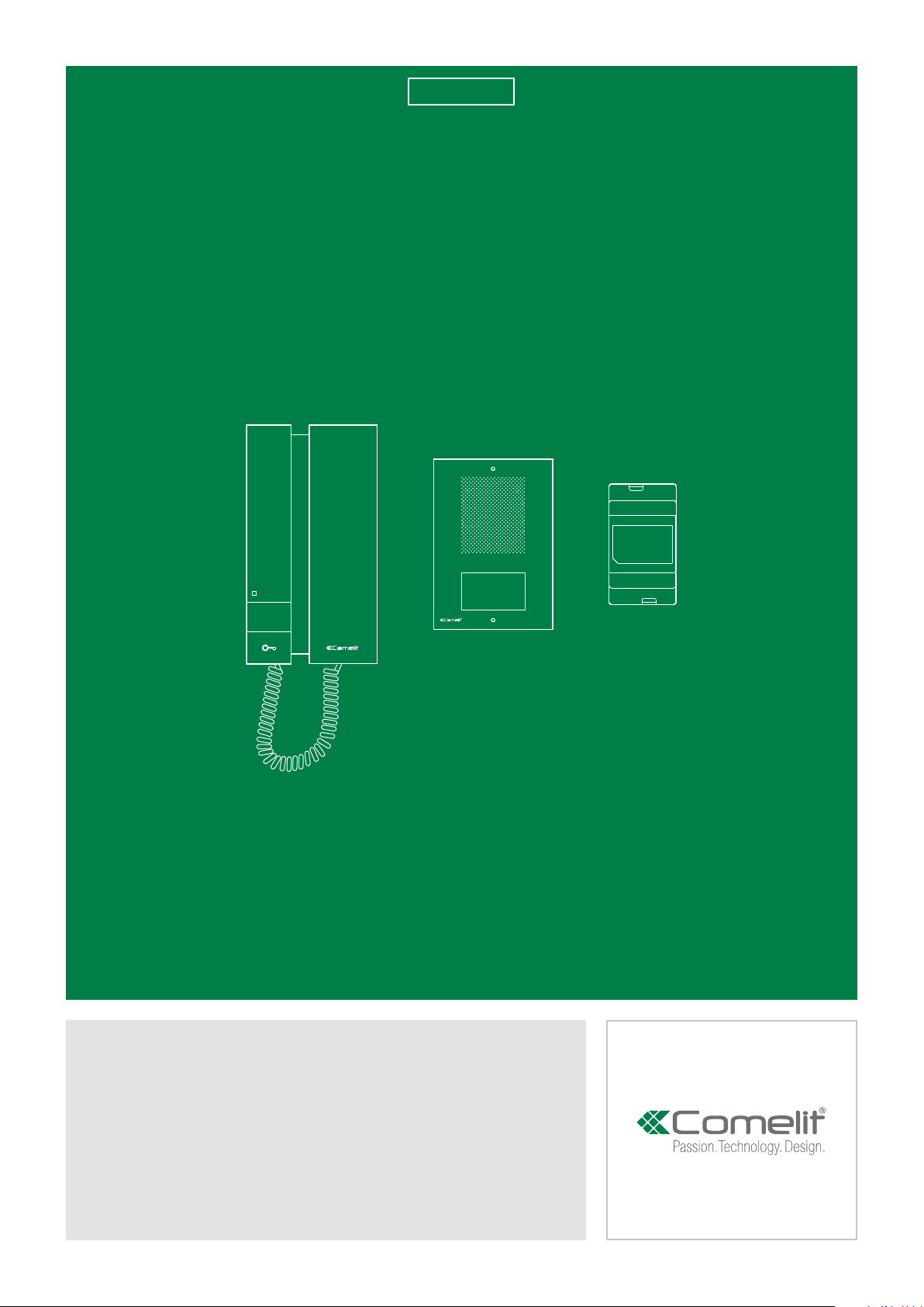
Single-family Kit
KAE0061
Page 2

Warning
Intended use
This Comelit product was designed for use in the creation of audio and video communication systems in residential,
commercial or industrial settings and in public buildings or buildings used by the public.
Installation
All activities connected to the installation of Comelit products must be carried out by qualified technical personnel, with
careful observation of the indications provided in the manuals / instruction sheets supplied with those products.
Wires
Disconnect the power supply before carrying out any operations on the wiring.
Use wires with a cross-section suited to the distances involved, observing the instructions provided in the system
manual.
We advise against running the system wires through the same duct as the power cables (230V or higher).
Safe usage
To ensure Comelit products are used safely:
• carefully observe the indications provided in the manuals / instruction sheets
• make sure the system created using Comelit products has not been tampered with / damaged.
Maintenance
Comelit products do not require maintenance aside from routine cleaning, which should be carried out in accordance
with the indications provided in the manuals / instruction sheets.
Any repair work must be carried out
• for the products themselves, exclusively by Comelit Group S.p.A.,
• for systems, by qualified technical personnel.
Disclaimer
Comelit Group S.p.A. does not assume any responsibility for
• any usage other than the intended use
• non-observance of the indications and warnings contained in this manual / instruction sheet.
Comelit Group S.p.A. nonetheless reserves the right to change the information provided in this manual / instruction
sheet at any time and without prior notice
Table of contents
Package contents ............................................................................ 3
Transformer art. 1200 ...................................................................... 4
Description ...............................................................................................4
External unit art. ET0001 ................................................................. 5
Description ...............................................................................................5
Installation ................................................................................................6
Nameplate holders ..............................................................................6
2
Internal unit art. 2712W ................................................................... 7
Description ...............................................................................................7
Installation ................................................................................................8
Wiring diagrams............................................................................... 9
Standard system ......................................................................................9
Using pushbutton 2 for various usages .................................................9
Connection of call repetition device ......................................................9
Operating distances ........................................................................ 9
Page 3
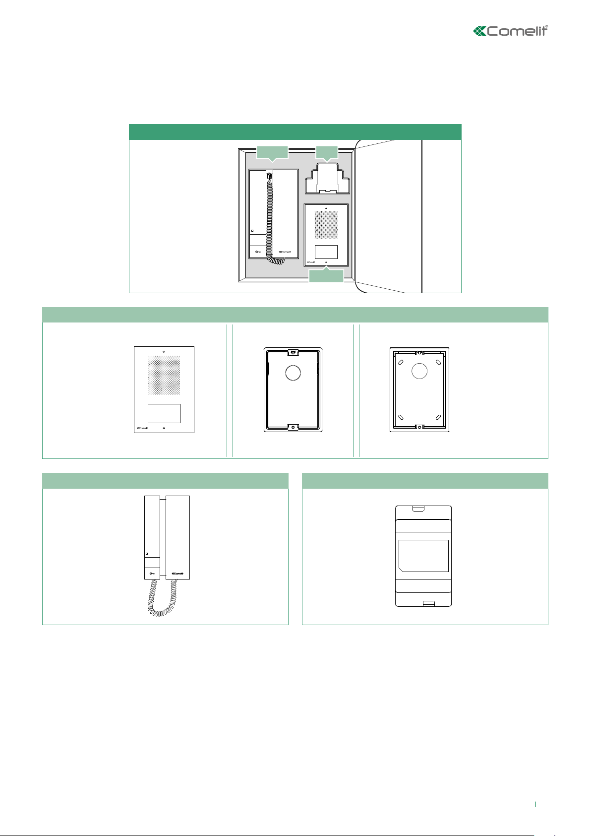
Package contents
1
This manual includes information regarding system configuration and customisation which may be perceived as necessary by
the installer.
KAE0061
2712W 1200
ET0001
ET0001 - External unit
×1 ×1 ×
2712W - Telephone 1200 -Transformer
×1
×1
3
Page 4

Transformer art. 1200
Description
Transformer with 230V primary, 12V AC / 15 VA secondary winding for continuous use.
Dimensions: 53 x 95 x 65 mm (3 DIN modules).
4
6
230 V~
1.
1
3
1. 230 V digital input.
2. Secondary 12 V AC output.
Disconnect the power supply before carrying out any maintenance procedures.
The electrical system of the building must be fitted with an omnipolar mains switch with a contact opening
of at least 3 mm, which is capable of isolating the power supply of the device.
Place the protection back over the terminals and close the inspection door after every procedure.
12 V~
2.
4
Page 5

External unit art. ET0001
Description
External unit complete with 1 call button, 1 wall bracket and 1 flush-mounted box.
Dimensions 95 × 135 × 26,5 mm (including wall bracket).
1.
2.
3.
4.
5.
6.
1. Surface-mounted wall bracket art. ET9160. A flush-mounted box art. ET9150 is also available
2. Stainless steel front faceplate
3. Faceplate fixing screw holes
4. Speaker
5. Call button
6. Microphone
7. Speaker
8. Terminal block for connection:
A B Connection of the internal units
C D Connection for electric door lock
9. TM1 Microphone volume adjustment trimmer
10. TM2 Balancing adjustment trimmer
11. TM3 Loudspeaker volume adjustment trimmer
7.
8.
9.
10.
11.
5
Page 6

Installation
9,5 cm
ET9160
ET9150
13,5 cm
CH2
21
1
1
2
CH2
2
3
3
6A5A4A
1
Nameplate holders
1
2
2
CH2
3
6B5B4B
1
2
3
1
2
2
6
321
Page 7

Internal unit art. 2712W
Description
Audio internal unit complete with 1 key button.
Dimensions 105×190×28 mm.
1.
6.
7.
2.
3.
4.
5.
1. Handset
2. 3-position ringtone/Privacy mode selector:
High position: Maximum ringtone volume
Middle position: Medium ringtone volume
Low position: Privacy mode activation (privacy mode means exclusion of the call ringtone from the external unit)
3. Red indicator - Privacy enabled
4. P1 button for various services
5. Key button
6. Loudspeaker
7. Audio hook
8.
9.
Do not press and hold the audio hook while the handset is lifted
8. Terminal block:
B A Connection of the external units
S- S+ Connection of the call repetition device
12~ 0~ Power supply terminals
P1 C Terminals for pushbutton P1 C. NO. 24V 100mA dedicated to various services
9. Handset connector
7
Page 8

Installation
mm 105
1
mm 190
2
max 7 cm
3
2
1
2
160 cm
2
130 cm
3A21
1
3
3
2
3
3
1
2
2
3D3C3B
1
1
1
1
2
1
1
CLACK!
2
654
CLACK!
7
8
Page 9

Wiring diagrams
A
B
C
D
CV1
Cut CV! if there is a lock connected
Local door-opener button
100 mA max
24 V DC
NOC
~~
12 0S
+
-
ASB C
1
P
~~
12
0S
+
-
ASB C
1
P
A
B
C
D
CV1
Cut CV! if there is a lock connected
Local door-opener button
~~
12
0S
+
-
ASB C
1
P
Standard system
P
12
ASB C
CV1
A
B
C
D
Cut
1
if there is a lock connected
CV
Using pushbutton 2 for various usages
0S
+
-
1
~~
Local door-opener button
Connection of call repetition device
Operating distances
ASB C
-
-
+
S 012
+
+-C
12 0S
~ ~
P
1
~~
NO
C
24 V DC
100 mA max
P
CBSA
1
470nF
NCN
O
1122/A
(12V)
12/24V
AC/DC
0,5 mm² 0,5 mm² 0,5 mm² 0,5 mm²
50 m 25 m 10 m 10 m
1 mm² 1 mm² 1 mm² 1 mm²
100 m 50 m 20 m 25 m
2 mm² 2 mm² 2 mm² 2 mm²
200 m 100 m 30 m 50 m
9
Page 10

1ª edizione 11/2017
cod. 2G40001779
CERTIFIED MANAGEMENT SYSTEMS
www.comelitgroup.com
Via Don Arrigoni, 5 - 24020 Rovetta (BG) - Italy
 Loading...