

Page 1
EN
TECHNICAL
MANUAL
Handsfree door entry phone
Mini 6750W, Mini 6751W
Passion.Technology.Design.
Page 2

Table of contents
Warning
Description ....................................................................................... 3
Art. 6750W .................................................................................................3
Art. 6751W .................................................................................................4
Technical characteristics ................................................................ 5
Wall-mounted ................................................................................... 6
Connections ..................................................................................... 8
Connection to the video entry riser and the floor door call button .....8
Branched connection to the video entry system riser from the internal
video unit...................................................................................................8
Connection to the door entry riser and the floor door call button ......8
Touch-sensitive buttons ................................................................. 9
Description ...............................................................................................9
Indicator LED ............................................................................................9
Answering an incoming call ....................................................................9
Activation / deactivation of Automatic answer mode ..........................9
Configuration ................................................................................. 10
Touch-sensitive buttons ........................................................................10
Legend ..............................................................................................10
Basic configuration ................................................................................10
Advanced configuration ........................................................................11
Warning .............................................................................................11
Intercom calls: introduction ..............................................................11
Selective intercom address: programming/cancellation ...................11
Intercom call: button programming...................................................12
Intercom call: direct programming ...................................................13
Generic actuator, Addressable actuator: button programming ........14
Other functions .................................................................................15
Programming range ...............................................................................16
Changing the ringtone ...........................................................................16
Programming reset ................................................................................17
System performance and layouts ................................................ 17
2
Page 3
Description
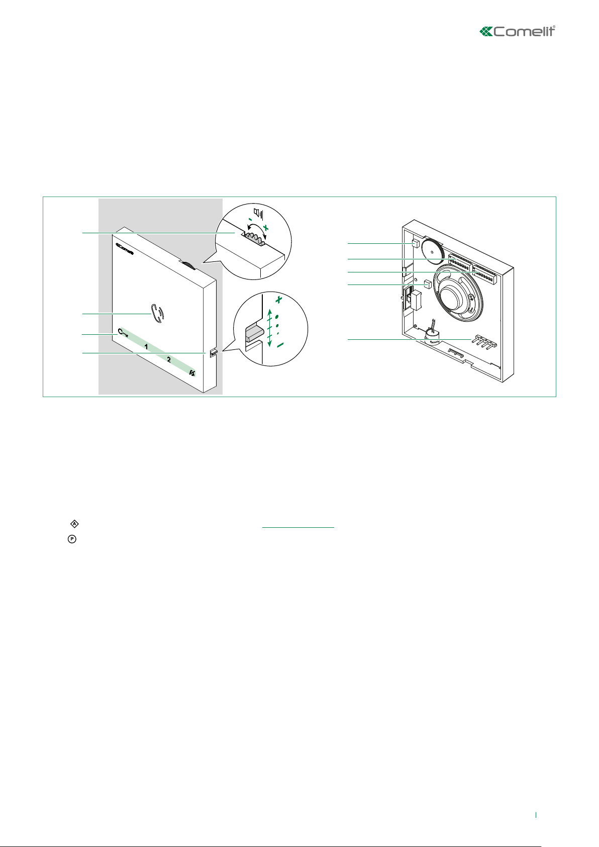
Art. 6750W
• Mini series handsfree door entry phone with full-duplex audio and integrated magnetic induction audio amplification system.
With 5 touch sensitive buttons for audio key, lock release, actuator, switchboard call and Privacy functions, and door status
indicator LED. Floor door call management as standard. Equipped with branch terminal art. 1214/2C.
• For use in SimpleBusTop audio/video systems with mixer art. 4888C, Building Kit systems with power supply unit
art.1210 or Audio/Video Kits with power supply unit art. 1209.
1.
2.
3.
4.
1. Loudspeaker volume control
f turn clockwise to increase the value
2. Speaker and audio activation button
3. Touch-sensitive buttons
4. Call volume adjustment (high - medium - low)
5. Trimmer - Factory setting DO NOT CHANGE!
6. S1
7. S2
8. Trimmer - Factory setting DO NOT CHANGE!
9. Pin for securing terminal block
Microswitches for setting the user code (see addressing table)
Microswitches for programming keys and functions
DIP 1-2-3-4 for button function programming
DIP 5-6 access to programming
DIP 7-8 not utilised
5.
6.
7.
8.
9.
Terminal block for system connection
LL Bus line connection terminals
CFP1 CFP2 Floor door call input
3
Page 4
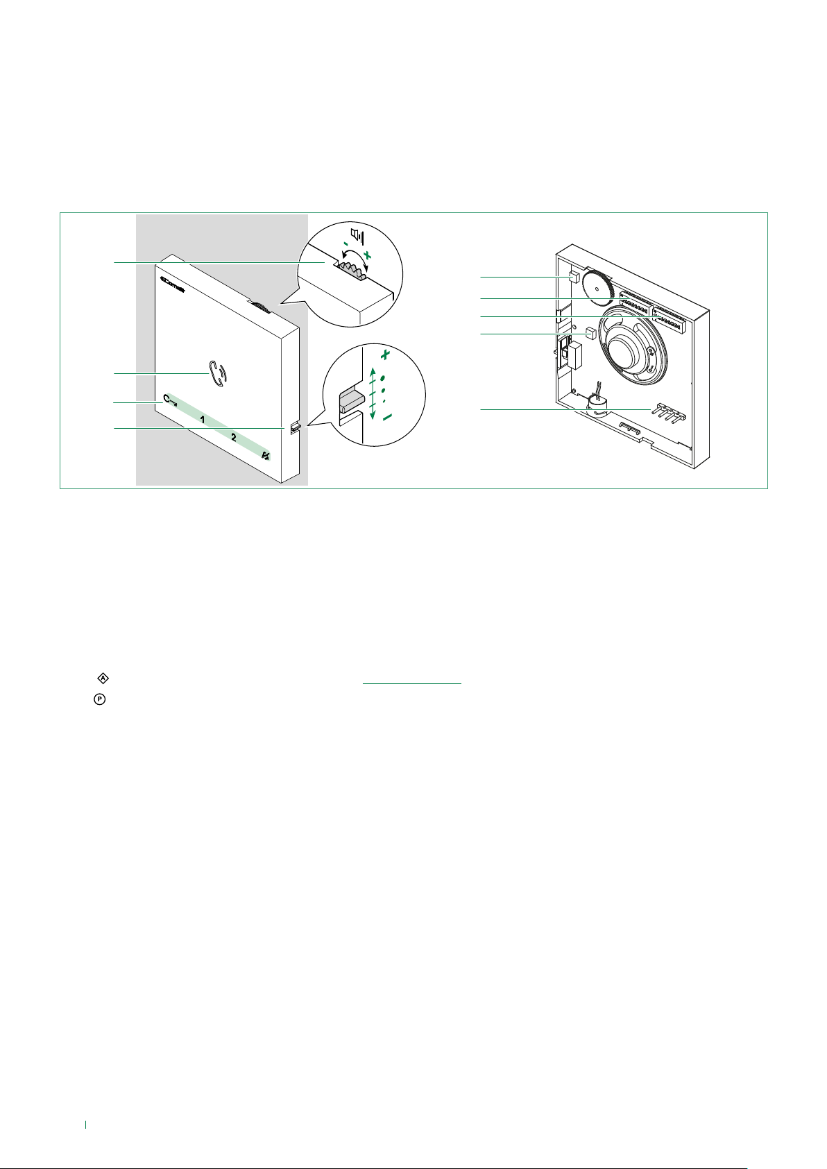
Art. 6751W
• Mini series door entry phone with full-duplex audio. With 5 touch sensitive buttons for audio key, lock release, actuator,
switchboard call and Privacy functions, and door status indicator LED. Floor door call management as standard.
• For use in SimpleBus2 audio systems with power supply unit art. 1210.
1.
2.
3.
4.
1. Loudspeaker volume control
f turn clockwise to increase the value
2. Speaker and audio activation button
3. Touch-sensitive buttons
4. Call volume adjustment (high - medium - low)
5. Trimmer - Factory setting DO NOT CHANGE!
6. S1
7. S2
8. Trimmer - Factory setting DO NOT CHANGE!
9. Pin for securing terminal block
Microswitches for setting the user code (see addressing table)
Microswitches for programming keys and functions
DIP 1-2-3-4 for button function programming
DIP 5-6 access to programming
DIP 7-8 not utilised
5.
6.
7.
8.
9.
Terminal block for system connection
LL Bus line connection terminals
CFP1 CFP2 Floor door call input
4
Page 5

Technical characteristics
MAIN SPECIFICATIONS
SimpleBus 2 audio system Yes Yes
SimpleBus Top audio/video system Yes NO
Building Kit audio/video system Yes NO
Audio/Video kit Ye s NO
Induction Loop system Yes NO
Branch terminal provided Yes NO
Wall-mounted Yes Yes
Full-duplex audio Yes Ye s
Product colour White White
Sensitive Touch technology Yes Yes
Total buttons 5 5
Additional buttons NO NO
LED signaling (No.) 3 3
FUNCTIONS
Actuator control functio Yes Yes
Switchboard call Yes Yes
Panic call Yes Yes
Intercom function Yes Yes
Selective intercom call Yes Yes
Call to multiple addresses Yes Ye s
Privacy mode Yes Yes
Doctor Yes Yes
Floor door call function Yes Yes
Electronic bell Yes Yes
Customisable ringtone Yes Yes
Art. 6750W Art. 6751W
HARDWARE SPECIFICATIONS
Removable terminals Yes Yes
SETTINGS
Loudspeaker volume control Yes Yes
Microphone volume control NO NO
Ringtone volume control Yes Yes
GENERAL INFO
Product height (mm) 105 105
Product width (mm) 105 105
Product depth (mm) 20 20
TECHNICAL CHARACTERISTICS
Power supply voltage 22-35 Vdc 22-35 Vdc
Absorption in standby (mA) 2 2
Maximum current absorption (mA) 130 130
IP Rating 30 30
Operating temperature (°C) -5 +40 -5 +40
Relative humidity for operation (%) 25-75 25-75
Product weight (g) 0,15 0,15
Terminals LL CFP1 CFP2 LL CFP1 CFP2
5
Page 6
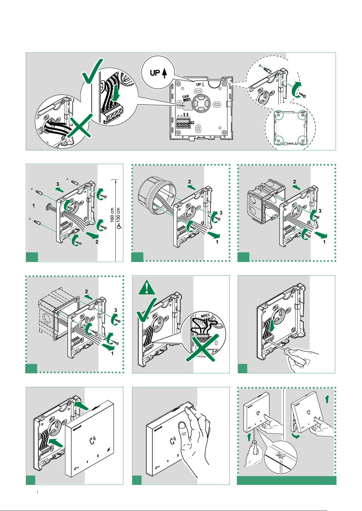
Wall-mounted
optional
4
1C1B1A
1D 2
CLACK!
3
1
3
6
4
» REMOVAL
2
Page 7
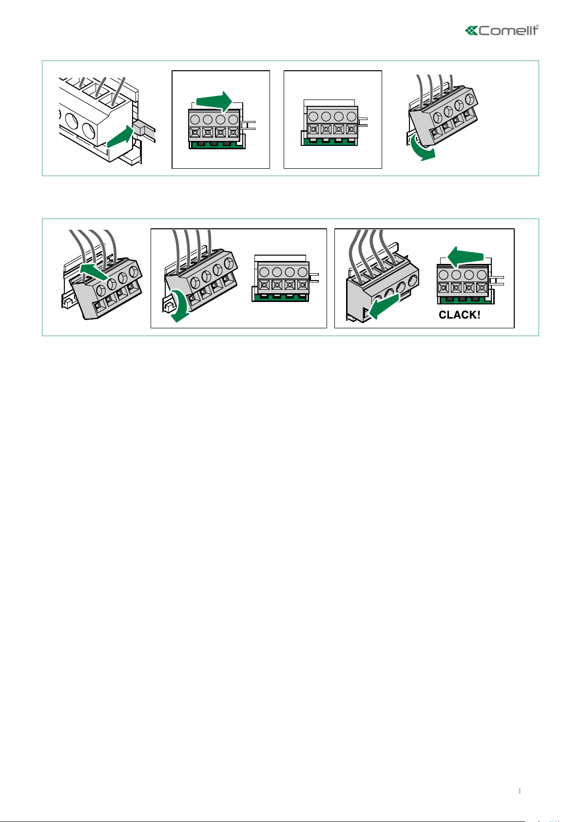
Terminal removal
1
Terminal installation
1
2
3
2
P
F
C
1
P
F
C
L L
2
3
7
Page 8
1209 / 1210 /4888C
1210
6751W
AUDIO ENTRY
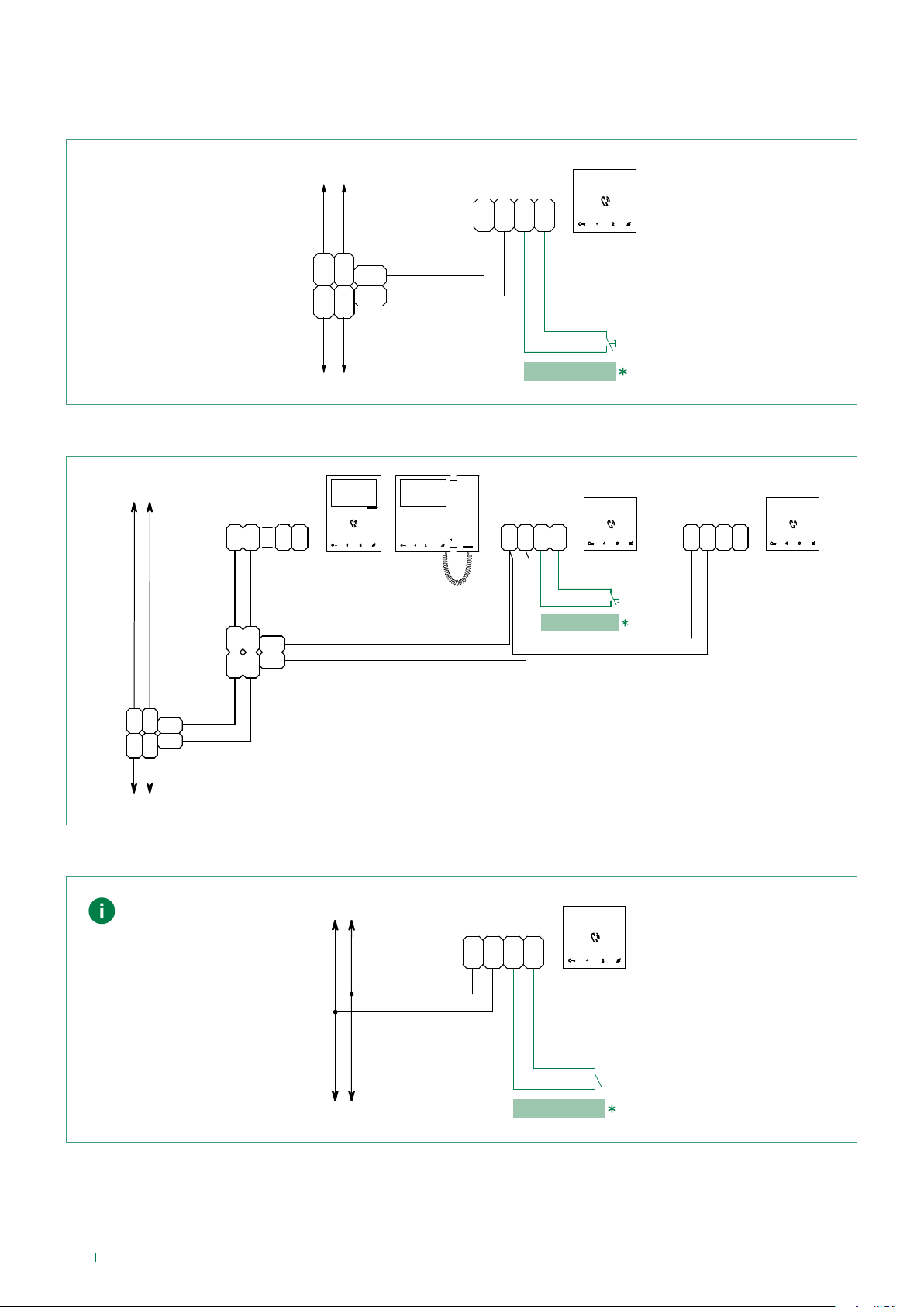
Connections
Connection to the video entry riser and the floor door call button
VIDEO ENTRY
SYSTEM RISER
LL
C
F1 2
P
6750W
C
F
P
1214/2C
L
L
OUT
OUT
LM
L
LM
INLIN
1209 / 1210 /4888C
FLOOR DOOR CALL
Branched connection to the video entry system riser from the internal video unit
VIDEO ENTRY
SYSTEM RISER
C
OUT
L
LINL
OUT
IN
LL
L
C
F
P
1214/2C
LM
LM
F
2
1
P
6721W
6721W/BM
6700W
6701W
6701B
L L
C
C
F1 2
F
P
P
FLOOR DOOR CALL
6750W
L L
C
F1 2
P
C
F
P
6750W
1214/2C
L
L
OUT
OUT
LM
L
LM
INLIN
Connection to the door entry riser and the floor door call button
Audio only systems
SYSTEM RISER
LL
C
C
F
F1 2
P
P
FLOOR DOOR CALL
* 20 m MAX - Use shielded cable for the connection and do not route the cables in the vicinity of heavy inductive loads or
power supply cables (230V/400V).
Where multiple door-entry phones or monitor backplates have the same user code, connect the CFP button on one only; all
the devices will ring simultaneously.
8
Page 9
Touch-sensitive buttons
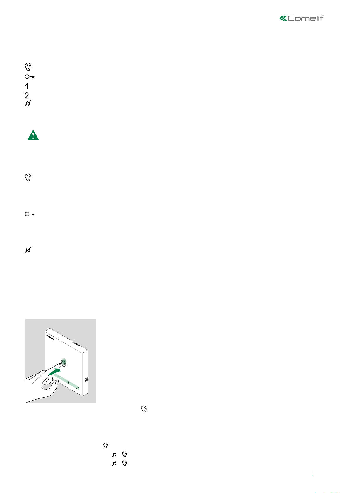
Description
Audio activation [programmable]
Lock release [programmable]
Actuator function [programmable]
Secondary switchboard [programmable]
Privacy Mode [not programmable]
f Press the desired button once to activate the associated function.
Wait for approximately 1 sec. before pressing the same button again. Pressing the same button several times in
quick succession will cancel the command.
Indicator LED
Audio LED
steady on (in call): communication in progress
steady on (in stand-by): Automatic answer mode activated
continuous flashing: incoming call
Lock release LED
slow flashing: door open
1 flash after pressing button: door open confirmed
continuous flashing: incoming call
Privacy LED (red)
steady on: Privacy mode activated
3 flashes (every 5 sec): Doctor function activated
continuous flashing: device in programming mode
4 flashes: system engaged
Answering an incoming call
Press the touch-sensitive audio activation button
to answer the incoming call.
Activation / deactivation of Automatic answer mode
f Long press (5 sec) the button
» ACTIVATION:
» DEACTIVATION:
+ LED STEADY ON
+ LED OFF
9
Page 10
Configuration
Touch-sensitive buttons
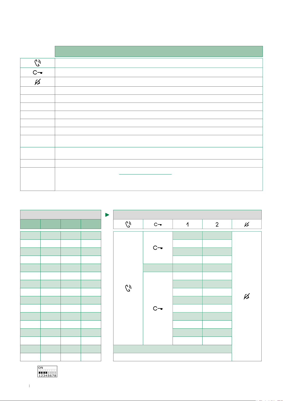
Legend
Audio
Lock-release
Privacy mode
ACT Actuator
CCP Call to main switchboard
CCS Call to secondary switchboard
K Caretaker door-entry phone call
D Doctor (Automatic door opening on receipt of call)
PAN Panic
INT
INTb
NULL No function
General or selective programmable intercom.
Default: single-family call
General or selective programmable intercom.
Default: two-family call
Programmed functions, see "Advanced configuration".
PROG.
With these DIP-switch settings, the buttons control the programmed functions;
The NON-programmed buttons control the functions on line 0000 *(Default).
Basic configuration
S2 BUTTON PROGRAMMING
DIP 1 DIP 2 DIP 3 DIP 4
0 0 0 0
1 0 0 0
0 1 0 0
1 1 0 0
0 0 1 0
1 0 1 0
0 1 1 0
1 1 1 0
0 0 0 1
1 0 0 1
0 1 0 1
1 1 0 1
ACT CCS
ACT INT
INT D
ACT CCP
ACT ACT ACT
ACT K
ACT D
INTb INT
CCS PAN
K CCS
CCP K
PAN CCP
0 0 1 1
1 0 1 1
0 1 1 1
1 1 1 1
* Default
10
INTb PAN
INT INT
NULL
PROG
Page 11
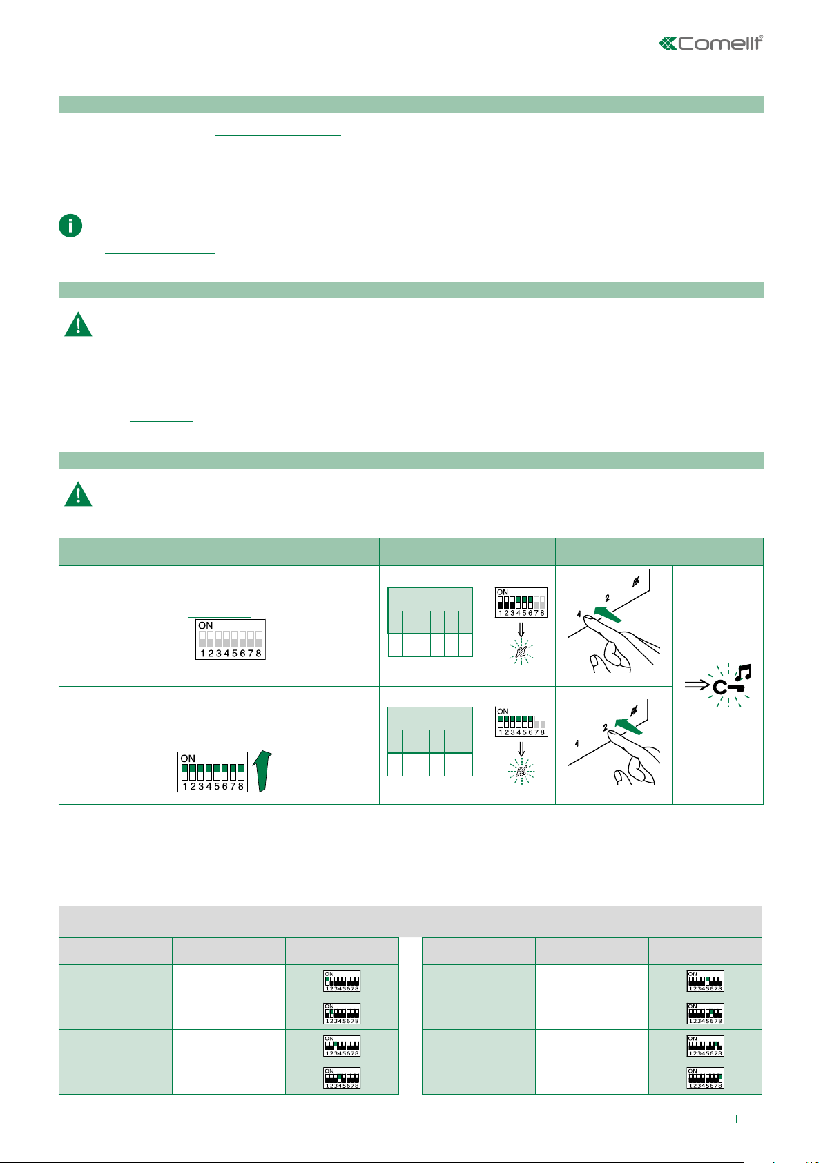
Advanced configuration
DIP OFF
DIP ON
Warning
If the default settings (Table "Basic configuration") do not reflect requirements, the buttons can be programmed dierently by
carrying out the steps below.
After programming, set S2 DIP switches 1-2-3-4 to the combination 1111. With these DIP-switch settings, the buttons
control the programmed functions.
The NON-programmed buttons control the basic configuration functions 0000. To restore the user code setting on
S1, see “addressing table”
Intercom calls: introduction
General and selective intercoms CANNOT be used together on the same riser.
General intercom: call from one internal unit to one or more internal units identified by the same call address as used
by the external unit.
Selective intercom: call from an internal unit to one or more internal units identified by a dedicated call address
(see"TABLE B") which is different from the call addressed used by the external unit.
Selective intercom address: programming/cancellation
Take note of the S2, S1 settings and restore on completion of programming
1) 2) 3)
Programming; set code,
"TABLE B"
S1
Cancellation
S1
Selective intercom addresses
You must set the intercom address on all the riser’s internal units.
You can assign the same intercom address to a maximum of 3 internal units.
For group calls, select the desired intercom codes simultaneously (max. 3).
S2 DIP
1 2 3 4 5 6
0 0 0 1 1 1
S2 DIP
1 2 3 4 5 6
1 1 1 1 1 1
S2
S2
TABLE B
Codice DIP switch ON S1 Codice DIP switch ON S1
1 1
2 2 6 6
3 3 7 7
4 4 8 8
5 5
11
Page 12
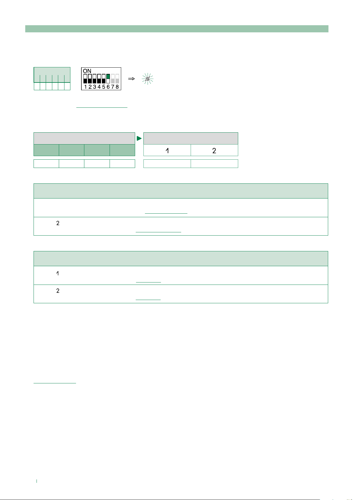
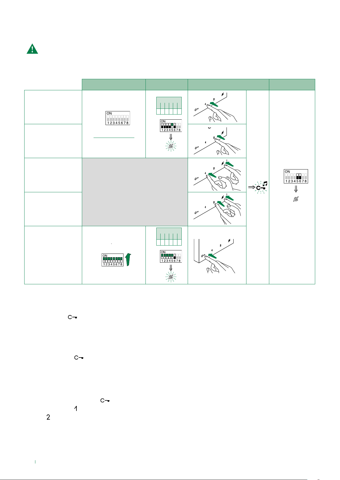
Intercom call: button programming
1. To enter programming mode, set S2 DIP-switch 6 to combination 1
» the Privacy LED flashes
S2 DIP
1 2 3 4 5 6
0 0 0 0 0 1
S2
2. Refer to the table Basic configuration and select a combination in which the intercom function is listed for the buttons you
wish to program.
Example
S2 BUTTON PROGRAMMING
DIP 1 DIP 2 DIP 3 DIP 4
1 0 1 1
INT INT
General intercom
Example programming of button 1 single-family general intercom, and button 2 general intercom to address 9, of a device
with user code 5.
(Button = INT) Set S2 DIP switches 1-2-3-4 to the combination 1 0 1 1,
set S1 with address 5 in accordance with the addressing table. Proceed with programming from point 3.
(Button = INT) Set S2 DIP switches 1-2-3-4 to the combination 1 0 1 1,
set S1 with address 9 in accordance with addressing table. Proceed with programming from point 3.
Selective intercom
Example programming of button 1 selective intercom to address 2 and button 2 selective intercom to address 3, of a
device with user code 1 and intercom address 1.
(Button = INT) Set S2 DIP switches 1-2-3-4 to the combination 1 0 1 1,
set S1 with address 2 in accordance with TABLE B .Proceed with programming from point 3.
(Button = INT) Set S2 DIP switches 1-2-3-4 to the combination1 0 1 1,
set S1 with address 3 in accordance with TABLE B. Proceed with programming from point 3.
3. Press and release the button to be associated with the function
» Correct procedure indication: the Lock release LED flashes for a few seconds and a confirmation tone sounds
» Procedure error indication: the Audio LED flashes for few seconds and an error tone sounds
4. To exit programming mode, set S2 DIP switch 6 to the combination 0
» the Privacy LED switches off
5. After programming, set S2 DIP switches 1-2-3-4 to the combination 1111. Restore the user code setting on S1 (see
addressing table.
12
Page 13

Intercom call: direct programming
Allows direct programming of intercom call via the internal units.
√ Requires 2 operators
Step 1: enter programming mode
Operator 1 and Operator 2 carry out the following procedures on 2 internal units:
1. Set S2 DIP switches 1-2-3-4 to the combination 1111
2. Press the Audio button
3. Press and hold the Privacy and Lock release buttons for 3 sec.
» The internal unit emits 1 tone.
» The Privacy LED flashes
» The internal unit enters audio mode.
» At this point the 2 operators are in communication with each other.
Step 2: intercom call programming
Operator 1:
f Press the button you want to program to call operator 2 (e.g. 2).
» The internal unit manned by operator 1 emits a confirmation tone.
Operator 2:
f Press the button you want to program to call operator 1 (e.g. 1).
» The internal unit manned by operator 2 emits a confirmation tone.
Operator 1/Operator 2:
f Press the Audio button
» The internal unit emits 1 tone.
» Programming of the 2 internal units is now complete.
To program another internal unit, go to STEP 3.
Step 3: programming other internal units
Operator 1/Operator 2:
1. Once the new station has been reached, carry out step 1 to begin communication.
2. Repeat step 2.
N.B. If a call is received during programming, it must be answered and the programming procedure resumed
afterwards.
13
Page 14
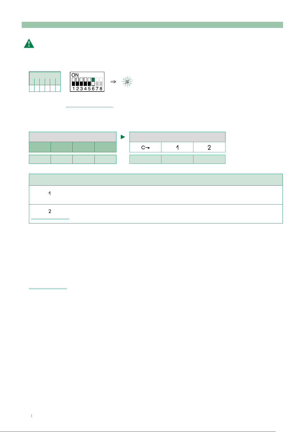
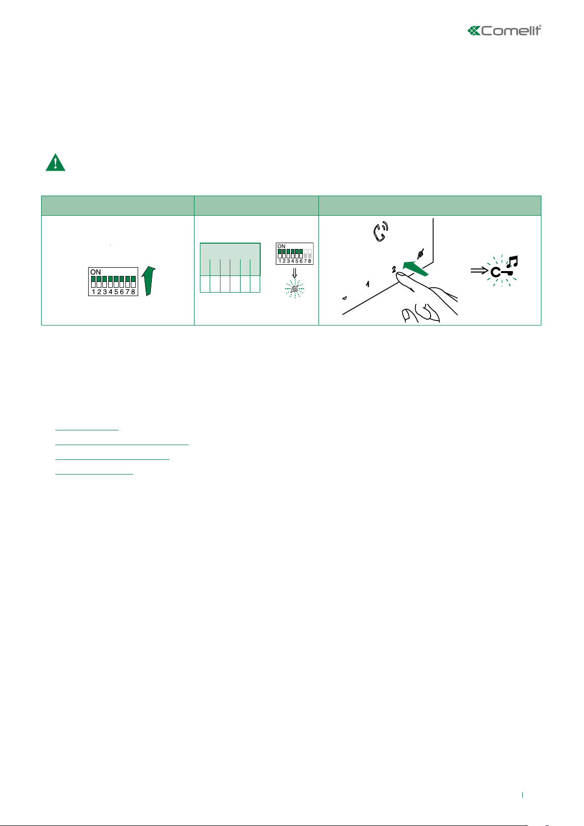
Generic actuator, Addressable actuator: button programming
Take note of the DIP-switch settings.
1. To enter programming mode, set S2 DIP switch 6 to combination 1
» the Privacy LED flashes
S2 DIP
1 2 3 4 5 6
0 0 0 0 0 1
S2
2. Refer to the table "Basic configuration" and select a combination in which the actuator function (ACT) is listed for the
buttons you wish to program.
Example
S2 BUTTON PROGRAMMING
DIP 1 DIP 2 DIP 3 DIP 4
0 0 1 0
ACT ACT ACT
Example programming of button 1 generic actuator, and button 2 addressable actuator to code 125
(Button
= ACT) Set S2 DIP switches 1-2-3-4 to the combination 0 0 1 0,
Set S1 DIP switches to the combination 11111111.
(Button = ACT) Set S2 DIP switches 1-2-3-4 to the combination 0 0 1 0, set S1 with address 125 in accordance with
addressing table.
3. Press and release the button to be associated with the function
» Correct procedure indication: the Lock release LED flashes for a few seconds and a confirmation tone sounds
» Procedure error indication: the Audio LED flashes for few seconds and an error tone sounds
4. To exit programming mode, set S2 DIP switch 6 to the combination 0
» the Privacy LED switches off
5. After programming, set S2 DIP switches 1-2-3-4 to the combination 1111. Restore the user code setting on S1, see
addressing table.
14
Page 15
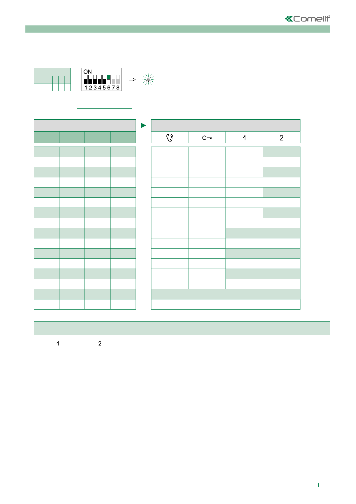
Other functions
1. To enter programming mode, set S2 DIP switch 6 to combination 1
» the Privacy LED flashes
S2 DIP
1 2 3 4 5 6
0 0 0 0 0 1
S2
2. Refer to the table "Basic configuration" and select a combination in which the desired/necessary functions are listed for
the buttons you wish to program.
S2 BUTTON PROGRAMMING
DIP 1 DIP 2 DIP 3 DIP 4
0 0 0 0
0 1 0 0
1 1 0 0
1 0 1 0
0 1 1 0
0 0 0 1
1 0 0 1
0 1 0 1
1 1 0 1
0 0 1 1
0 1 1 1
NULL
1 1 1 1 PROG
CCS
D
CCP
K
D
CCS PAN
K CCS
CCP K
PAN CCP
PAN
Example programming of button 1 Call to secondary switchboard and button 2 Panic.
(Button
= CCS, Button = PAN) Set S2 DIP switches 1-2-3-4 to the combination 0 0 0 1.
3. Press and release the buttons to which you wish to assign the functions
» Correct procedure indication: the Lock release LED flashes for a few seconds and a confirmation tone sounds
» Procedure error indication: the Audio LED flashes for few seconds and an error tone sounds
4. To exit programming mode, set S2 DIP switch 6 to the combination 0
» the Privacy LED switches off
5. After programming, set S2 DIP switches 1-2-3-4 to the combination 1111.
15
Page 16
DIP OFF
DIP ON
Programming range
Take note of the S2, S1 settings and restore on completion of programming
Carry out steps 1 to 4
1) 2) 3) 4)
Range minimum
address
Range maximum
address
Enable range
Disable range
Deleting the range
S1
set code,
addressing table
S1
1 2 3 4 5 6
0 0 0 0 1 0
S2
1 2 3 4 5 6
1 1 1 1 1 0
S2
S2 DIP
S2
S2 DIP
2 sec
Changing the ringtone
1. Press and hold
» a confirmation tone will sound
» the Privacy LED will flash to indicate "programming" mode.
√ the procedure can only take place while the system is in standby; otherwise the Privacy LED will flash 4 times to inform the
user that the system is engaged.
2. Press and release
Once (1 confirmation tone is emitted) to change the ringtone for calls from the external unit.
Twice (2 confirmation tones emitted) to change the switchboard call tone
3 times (3 confirmation tones are emitted) to change the ringtone for intercom calls made from the internal unit.
4 times (4 confirmation tones are emitted) to change the floor door call ringtone.
Any further presses of button
3. Press and release
4. Press
to confirm selection of the last ringtone heard and to exit change monitor ringtone mode.
» one confirmation tone is emitted
» the Privacy LED switches o
Repeat steps 1 to 4 to change the other ringtones.
16
for 6 sec.
will repeat the sequence described above.
to scroll through the various available ringtones in sequence.
Page 17
DIP OFF
DIP ON
Programming reset
Factory settings
• Button functions for the S2 DIP switches 1-2-3-4 combination
• Intercom address absent
• Range function and min./max. addresses absent
• Ringtone reset
Take note of the S2, S1 settings and restore on completion of programming
1) 2) 3)
S1
S2 DIP
1 2 3 4 5 6
1 1 1 1 1 1
S2
5 sec
System performance and layouts
For further information of system performance and to view installation layouts, click on the system type that best meets your
requirements:
• Audio/video kit for the creation of audio-video systems for individual residences
• Building Kit audio/video system for the creation of audio-video systems for small apartment blocks
• SBTOP audio/video system for the creation of audio-video systems for residential complexes
• SB2 audio system for the creation of audio systems for residential complexes
17
Page 18

1ª edizione 09/2017
cod. 2G40001880
CERTIFIED MANAGEMENT SYSTEMS
www.comelitgroup.com
Via Don Arrigoni, 5 - 24020 Rovetta (BG) - Italy
 Loading...