

Page 1
INSTALLATION & OPERATION
MANUAL
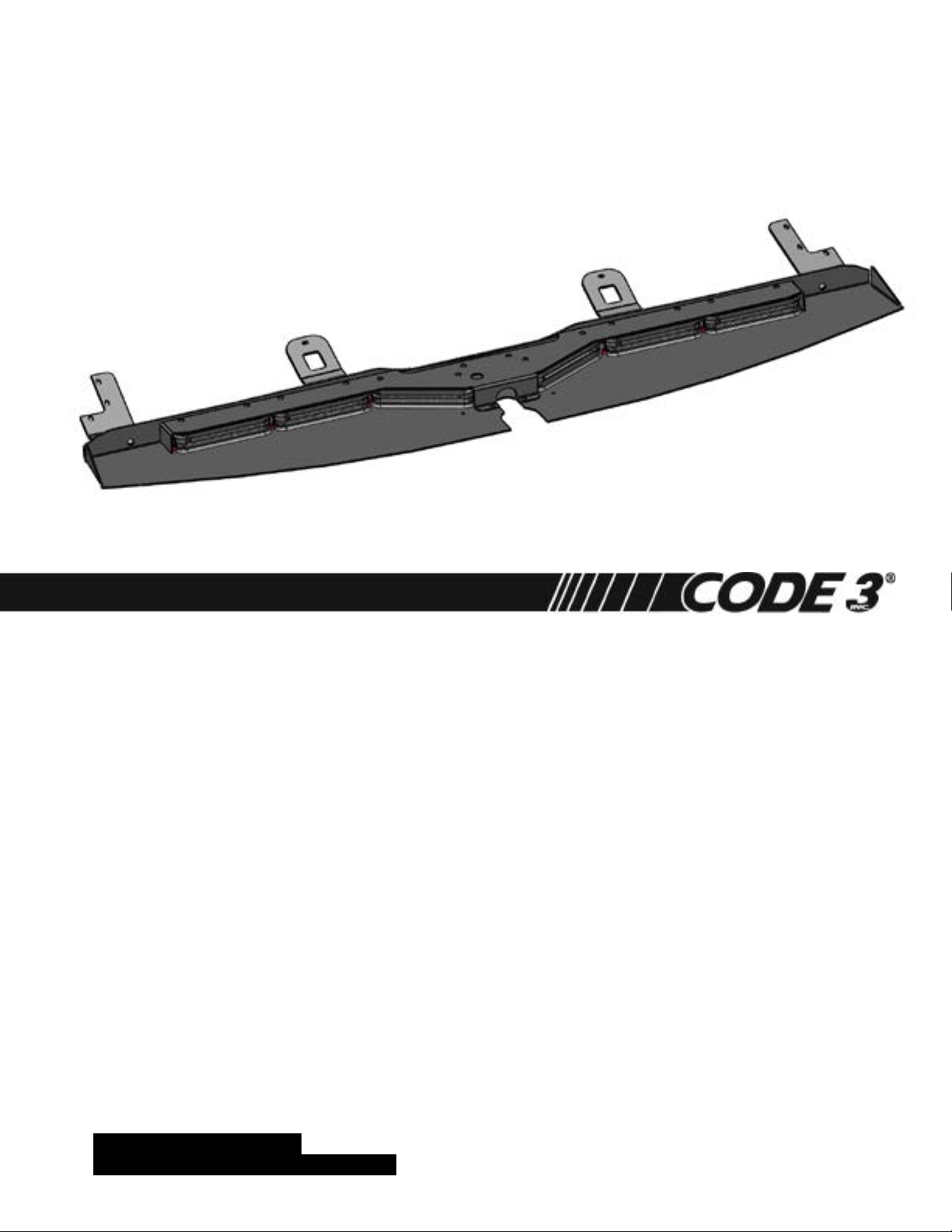
SuperVisor-MC™ - 2011 CHEVY CAPRICE
With Multi Color Torus™ Technology
Interior Lighting System
CONTENTS:
Introduction ............................................................................. .2
Unpacking & Pre-Installation ...................................................2
Installation & Mounting ......................................................3-6
Wiring Instructions .............................................................6-8
LED Flash Rate / Sequence Selection ....................................8
Cruise, Take Down Steady ......................................................9
Exploded Views - Parts & Hardware List........... ..............9-10
Troubleshooting, Notes...........................................................11
Warranty .............................................................................12
For future reference record your product's serial no. here __________________________________________
IMPORTANT:
Read all instructions and warnings before installing and using.
This manual must be delivered to the end user of this equipment.
INSTALLER:
Page 2

Introduction
The Multi Color SuperVisor-MC™ (hereafter called "Unit") is an interior lighting system that ts in the visor area near the top of the
windshield. The SuperVisor-MC has room for up to (6) Torus Multi Color Light Heads.
Product Features
Torus Multi Color Light Head Options: Red/White, Blue/White, Amber/White, Red/Blue, Red/Amber, Blue/Amber
Size: 44.29" long x 1.50" tall x 6.94" deep-----------------------------------------Weight: 7.5 lbs
The use of this or any warning device does not ensure that all drivers can or will observe or react to an
emergency warning signal. Never take the right-of-way for granted. It is your responsibility to be sure you can
proceed safely before entering an intersection, driving against trafc, responding at a high rate of speed, or
walking on or around trafc lanes. The effectiveness of this warning device is highly dependent upon correct
mounting and wiring. Read and follow the manufacturer’s instructions before installing or using this device. The
vehicle operator should insure daily that all features of the device operate correctly. In use, the vehicle operator
should insure the projection of the warning signal is not blocked by vehicle components (i.e.: open trunks or
compartment doors), people, vehicles, or other obstructions. This equipment is intended for use by authorized
personnel only. It is the user’s responsibility to understand and obey all laws regarding emergency warning
devices. The user should check all applicable city, state and federal laws and regulations. Code 3, Inc., assumes
no liability for any loss resulting from the use of this warning device. Proper installation is vital to the performance
of this warning device and the safe operation of the emergency vehicle. It is important to recognize that the
operator of the emergency vehicle is under psychological and physiological stress caused by the emergency
situation. The warning device should be installed in such a manner as to: A) Not reduce the output performance
of the system, B) Place the controls within convenient reach of the operator so that he can operate the system
without losing eye contact with the roadway. Emergency warning devices often require high electrical voltages
and/or currents. Properly protect and use caution around live electrical connections. Grounding or shorting of
electrical connections can cause high current arcing, which can cause personal injury and/or severe vehicle
WARNING!
damage, including re. Any electronic device may create or be affected by electromagnetic interference. After
installation of any electronic device operate all equipment simultaneously to insure that operation is free of
interference. Never power emergency warning equipment from the same circuit or share the same grounding
circuit with radio communication equipment. All devices should be mounted in accordance with the manufacturer's
instructions and securely fastened to vehicle elements of sufcient strength to withstand the forces applied to the
device. Driver and/or passenger air bags (SRS) will affect the way equipment should be mounted. This device
should be mounted by permanent installation and within the zones specied by the vehicle manufacturer, if any.
Any device mounted in the deployment area of an air bag will damage or reduce the effectiveness of the air
bag and may damage or dislodge the device. Installer must be sure that this device, its mounting hardware and
electrical supply wiring does not interfere with the air bag or the SRS wiring or sensors. Mounting the unit inside
the vehicle by a method other than permanent installation is not recommended as unit may become dislodged
during swerving, sudden braking or collision. Failure to follow instructions can result in personal injury. PROPER
INSTALLATION COMBINED WITH OPERATOR TRAINING IN THE PROPER USE OF EMERGENCY WARNING
DEVICES IS ESSENTIAL TO INSURE THE SAFETY OF EMERGENCY PERSONNEL AND THE PUBLIC.
Unpacking & Pre-installation
Carefully remove the Unit and place it on a at surface, taking care not to scratch the lenses or damage the cable coming out of the
Housing. Examine the unit for transit damage, broken optics, LED's, etc. Report any damage to the carrier and keep the shipping carton.
The Multi Color SuperVisor-MC light bar is built to operate on 12 volt D.C. negative ground (earth). The Unit will not operate properly if
you have an electrical system other than 12 volt D.C. negative ground (earth).
Test the unit before installation. To test, touch the black wire to the ground (earth) and the other wires to +12 volts D.C., in accordance
with the instructions attached to the cable and as shown in the Multi Color SuperVisor Internal Wiring Diagram at the top of page 8 of this
manual (an automotive battery is preferable for this test). A battery charger may be used, but note that some electronic options may not
operate normally when powered by a battery charger. If problems occur at this point, contact the factory.
WARNING!
Mounting Hardware - All mounting hardware is packed in a small bag inside the main carton. There are four brackets used to mount
the SuperVisor to the vehicle. These are discussed in detail later.
Utilizing non-factory supplied screws and/or mounting brackets and/or the improper
number of screws may result in loss of warranty coverage on the equipment.
2
Page 3

Installation Instructions-All Figures are shown on Pages 4, 5 & 6
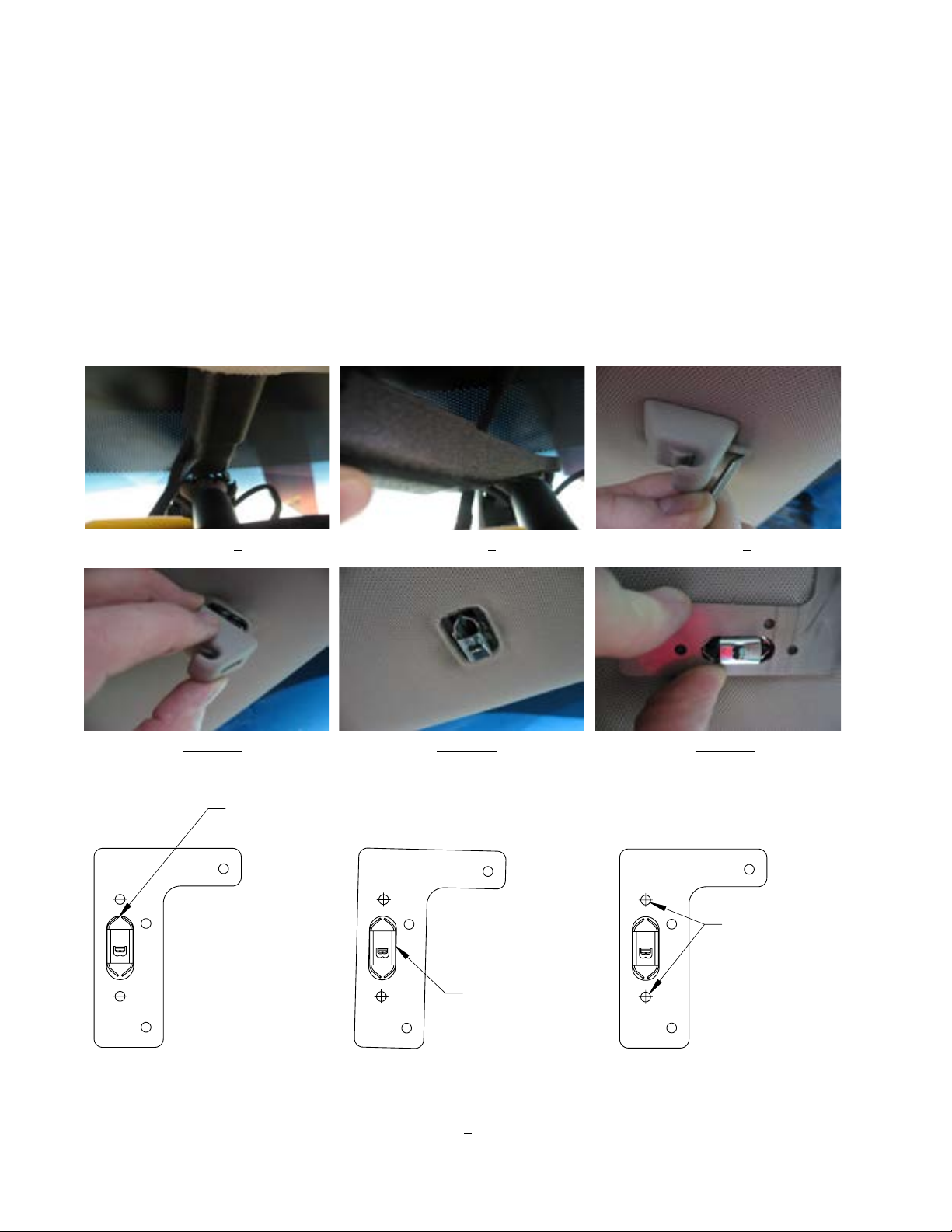
Step-1 Remove the vehicle's plastic rear view mirror wiring cover by sliding the upper sleeve portion down and forward to disengage
it from the vehicle's headliner (see Figure 1), then pull the cover off of the rear view mirror mounting bracket (see Figure 2). Discard or
store away the vehicle's plastic rear view mirror wiring cover as desired as it will not be reused for mounting the SuperVisor.
Step-2 With a small thin screw driver, remove the plastic fastening wedges that retain the vehicles's plastic inner visor clips, as
shown in Figure 3, then remove the plastic visor clips, plastic visor clip detent, and the detent spring from the vehicle's sheet metal
bracket (see Figure 4). The two inner visor clip areas of the vehicle should now look as shown in Figure 5.
Step-3 Position the supplied Sheet Metal Drilling Template over the vehicle's sheet metal visor clip bracket as shown in Figure 6.
Caution: Make absolutely certain that the Sheet Metal Drilling Template is centered over the vehicle's
sheet metal visor clip bracket in both directions and that it is held parallel to the bracket (See Figure
7 for correct and incorrect positioning). It is very important that the Drilling Template does not move
while drilling the holes! It is highly recommended that you have an assistant hold the template so that it
doesn't move while you drill the holes and to keep the holes from being drilled crooked or out of location.
While holding the Drilling Template so that it does not move, drill (2) 9/64" diameter holes one at each end of the slot in the
Drilling Template through the headliner material and through the rst layer of the Caprice's headliner sheet metal. (see Figure 7 again,
also see Figures 8 and 9). Caution: Only drill through the rst layer of the vehicle's sheet metal. Be very care-
ful not to drill all the way through the vehicle's roof!
Step-4 Loop a piece of wire through the vehicle's sheet metal visor clip bracket to prevent it from accidentally popping up into the
hole in the headliner and using a pair of plyers compress the (4) side retention tabs of the vehicles sheet metal visor clip bracket and
pull the bracket down out of the hole in the headliner (see Figure 10). Repeat this step for both of the brackets. Discard or store away
the vehicle's inner visor clip assembly as desired as it will not be reused for mounting the SuperVisor.
Step-5 Position the supplied Sheet Metal Drilling Template against the vehicle's plastic outer visor pivot brackets as shown in Figure
11-Driver Side and Figure 12-Passenger Side. Caution: Make absolutely certain that the Sheet Metal Drilling Tem-
plate is held tight against the vehicle's plastic outer visor pivot brackets in both directions as shown
and noted in Figures 11 and 12. Again as stated in Step-3, it is very important that the Drilling Template
does not move while drilling the holes. Again, it is highly recommended that you have an assistant hold
the template so that it doesn't move while you drill the holes and to keep the holes from being drilled
crooked or out of location! While holding the SuperVisor's Drilling Template so that it does not move, drill (3) 9/64" diameter
holes at each of the (3) hole locations indicated in Figures 11 and 12 (see Figures 13,14, and 15-Drivers Side Shown).
Step-6 Position the supplied Plastic Inner Visor Clips into the rectangular hole in the supplied Inner Mounting Brackets as shown
in Figure 16, then position the Inner Mounting Brackets with the Plastic Inner Visor Clips over the rectangular hole in the vehicle's
headliner, align the slotted holes in the Inner Mounting Brackets and the holes in the Plastic Inner Visor Clips with the holes drilled in
Step-3 and thread (2) supplied Black Oxided #8 X 1" Phillips Truss Head Sheet Metal Screws as shown in Figures 17 and 18. Only
thread the screws in about half way to get them started so that they will screw in and out easily for adjustment later, do not tighten the
screws at this time.
Step-7 Position the supplied Driver and Passenger Side Outer Mounting Brackets as shown in Figure 19 (Driver Side Shown), align
the slotted holes in the Mounting Brackets with the holes drilled in Step-5, and thread the (3) supplied Black Oxided #8 X 1" Phillips
Truss Head Sheet Metal Screws through the (3) slotted holes in each of the Outer Mounting Brackets and into the holes that were
drilled in the vehicle in Step 5. Only thread the screws in about half way to get them started so that they will screw in and out easily for
adjustment later. Do not tighten the screws at this time (again see Figure 19).
Step-8 Route the SuperVisor's cable to the desired side of the vehicle and through the cable slot at the end of the Outer Panel.
Make sure the cable will not interfere with the vehicle's headliner and windshield as you position the SuperVisor up to the headliner
and in front of the Inner Mounting Brackets (see Figure 20). Thread the supplied 1/4"-20 screws and internal tooth lock washers
through the slots in the Inner Mounting Brackets and into the Outer Panel (see Figure-21). Thread the supplied 1/4"-20 screws and
internal tooth lock washers through the slots in the Outer Mounting Brackets and into the Outer Panel (see Figure-22-Drivers Side
Shown). Thread all (4) of the 1/4"-20 screws up to minimize the slack between the Mounting Brackets and the SuperVisor but do not
fully tighten the screws at this time. A small amount of slack is needed for adjustment later.
3
Page 4
Installation Instructions Cont.
NOT CENTERED
WRONG WRONG
CORRECT
Step-9 While making sure the SuperVisor is centered in the vehicle tighten all of the Black Oxided #8 X 1" Phillips Truss Head Sheet
Metal Screws (see Figures 17, 18, and 19). Tighten each of the screws a little at a time so that they are all tightened somewhat simultaneously, this will help keep the SuperVisor centered.
Step-10 While pushing the SuperVisor very tightly up against the headliner, tighten the (2) 1/4"-20 Inner Mounting Bracket screws as
shown in Figure 23 then tighten the (2) 1/4"-20 Outer Mounting Bracket screws as shown in Figure 24. The idea is to slightly crush the
SuperVisor's Sheet Metal Headliner Flange into the vehicle's headliner fabric to prevent light from ashing through into the Driver's eyes.
Note: It is best to have an assistant push up on the SuperVisor while you tighten each of the the screws to assure that it is tight
against the vehicle's headliner.
Step-11 Tighten the Vehicle's Driver and Passenger Side #8 Torx outer pivot bracket mounting screws as shown in Figures 25 and 26.
Step-12 Route the SuperVisor's Cable as desired.
FIGURE 1 FIGURE 2 FIGURE 3
FIGURE 4 FIGURE 5 FIGURE 6
IN THE SLOT
DRILL HOLES
AT THESE
LOCATIONS
ANGLED
IN THE SLOT
FIGURE 7
4
Page 5

Installation Instructions Cont.
FIGURE 8 FIGURE 9 FIGURE 10
THE SUPERVISOR'S
DRILLING TEMPLATE
MUST BE HELD TIGHT
AGAINST THE EDGES
OF THE VEHICLE'S
PLASTIC VISOR PIVOT
BRACKET
DRIVERS SIDE
FRONT
OF VEHICLE
DRILL HOLES AT
THESE LOCATIONS
DRILL HOLES AT
THESE LOCATIONS
PASSENGER
FRONT
OF VEHICLE
SIDE
THE SUPERVISOR'S
DRILLING TEMPLATE
MUST BE HELD TIGHT
AGAINST THE EDGES
OF THE VEHICLE'S
PLASTIC VISOR PIVOT
BRACKET
FIGURE 11 FIGURE 12
FIGURE 13-DRIVER SIDE SHOWN FIGURE 14-DRIVER SIDE SHOWN FIGURE 15-DRIVER SIDE SHOWN
FIGURE 16 FIGURE 17 FIGURE 18
FIGURE 19-DRIVER SIDE SHOWN FIGURE 20 FIGURE 21
5
Page 6

Installation Instructions Cont.
FIGURE 22 FIGURE 23 FIGURE 24
FIGURE 25-DRIVER SIDE FIGURE 26-PASSENGER SIDE
Caution: Drilling into the housing of the light bar could damage wiring or other internal
components.
Wiring Instructions
Finish routing the cable as desired. It is advisable to leave an extra loop of cable when installing the light bar to allow for
future changes or reinstallations. For wiring of the Multi Color SuperVisor, see pages 7 & 8.
LED Fusing Considerations
NOTE: The Components of the Multi Color SuperVisor System are circuit protected by the Multi Color SuperVisor System CC
Board so the individual wires in the System do not require fusing.
DO NOT APPLY 12 VOLTS DIRECTLY TO THE SUPERVISOR WIRES AFTER IT IS CONNECTED TO THE
SUPERVISOR MULTI COLOR CC BOX. THE MULTI COLOR SUPERVISOR CC BOARD OR THE LIGHT
WARNING!
WARNING!
HEADS COULD BE DAMAGED BY APPLYING 12 VOLTS TO THE CC OUTPUTS!.
Larger wires and tight connections will provide longer service life for components. For high current wires it
is highly recommended that terminal blocks or soldered connections be used with shrink tubing to protect
the connections. Do not use insulation displacement connectors (e.g. 3M® Scotchlock type connectors).
Route wiring using grommets and sealant when passing through compartment walls. Minimize the
number of splices to reduce voltage drop. High ambient temperatures (e.g. under hood) will signicantly
reduce the current carrying capacity of wires, fuses, and circuit breakers. Use "SXL" type wire in engine
compartment. All wiring should conform to the minimum wire size and other recommendations of the
manufacturer and be protected from moving parts and hot surfaces. Looms, grommets, cable ties, and
similar installation hardware should be used to anchor and protect all wiring. Fuses or circuit breakers
should be located as close to the power takeoff points as possible and properly sized to protect the wiring
and devices. Particular attention should be paid to the location and method of making electrical connections
and splices to protect these points from corrosion and loss of conductivity. Ground terminations should
only be made to substantial chassis components, preferably directly to the vehicle battery. The user should
install a fuse sized to approximately 125% of the maximum Amp capacity in the supply line to protect
against short circuits. For example, a 30 Amp fuse should carry a maximum of 24 Amps. DO NOT USE
1/4" DIAMETER GLASS FUSES AS THEY ARE NOT SUITABLE FOR CONTINUOUS DUTY IN SIZES
ABOVE 15 AMPS. Circuit breakers are very sensitive to high temperatures and will "false trip" when
mounted in hot environments or operated close to their capacity.
6
Page 7

MULTI COLOR SUPERVISOR & CC WIRING DIAGRAM
BROWN / WHITE BROWN / WHITE
GREEN / WHITE GREEN / WHITE
ORANGE ORANGE
LIGHT BLUE LIGHT BLUE
WHITE WHITE
PINK PINK
GREEN GREEN
RED / WHITE RED / WHITE
RED RED
LIGHT BLUE / WHITE LIGHT BLUE / WHITE
PURPLE PURPLE
BROWN BROWN
MULTI COLOR
SUPERVISOR
CABLE
CONTROL INPUT
WIRES CONNECT TO
DESIRED SIREN
CONTROLLER OR
EXTERNAL
SWITCHES
MULTI COLOR SUPERVISOR
OUTPUT WIRES - CONNECT
ALL OUTPUT WIRES TO THE
MATCHING COLOR WIRES IN
THE SUPERVISOR CABLE
NOTE: COLOR SHADES MAY
VARY SLIGHTLY
AFTER CUTTING CABLE TO DESIRED LENGTH
STRIP WIRES, CRIMP SUPPLIED FEMALE QUICK
GREEN / BLACK-------LEVEL-1
WHITE / BLACK--------LEVEL-2
RED / BLACK------------LEVEL-3
BLUE / WHITE-----------DIMMING MODE
BLACK / WHITE---------CRUISE MODE
RED / WHITE-------------FLASH SEQUENCE SELECT
BLACK / RED------------FLASH RATE SELECT
BLACK---------------------TAKE DOWN STEADY
ORANGE / BLACK-----SCENE STEADY
SLIDES, AND COMPLETE THE CONNECTIONS 12X
CUSTOMER
SUPPLIED
WIRES RUN TO
Z3 SIREN OR
OTHER
SWITCHING
SYSTEM
CUSTOMER SUPPLIED
22 AMP BUTT SPLICE
TYPICAL
NOTE: FOR CALIFORNIA TITLE-13
STEADY RED TIE THE
RED / WHITE "FLASH
SEQUENCE WIRE" &
THE BLACK / RED
"FLASH RATE WIRE"
TO 12 VDC OR
TO A SWITCH THAT IS
TIED TO 12 VDC
VEHICLE BATTERY
7
POWER & GROUND WIRES
WILL REQUIRE CUSTOMER
SUPPLIED 12 GAGE WIRE,
12 GAGE BUTT SPLICES, &
20 AMP FUSE
Page 8

LIGHT BLUE/WHITE
PRIMARY
PURPLE
PRIMARY
RED
PRIMARY
PASSENGER SIDE 2011 CAPRICE DRIVER SIDE
RED/WHITE
PRIMARY
BROWN
PRIMARY
GREEN
PRIMARY
LIGHT BLUE
SECONDARY
WHITE
SECONDARY
ORANGE
SECONDARY
BROWN/WHITE
SECONDARY
PINK
SECONDARY
GREEN/WHITE
SECONDARY
MULTI COLOR SUPERVISOR INTERNAL WIRING DIAGRAM
NOTE: THIS IS THE LOCATION
FOR THE CALIFORNIA
STEADY BURN RED
LIGHT HEAD
WARNING!
This Product contains high intensity LED devices. To prevent eye
damage, DO NOT stare into light beam at close range.
Changing Flash Rates and Lighting Sequences
To change Multi Color SuperVisor Light Head ash rates, momentarily touch the Black Wire with Red Stripe (Flash Rate Control Wire) to 12
VDC Power (+ Positive). By holding the wire to + Positive for (1) second it will advance the ash rate by one, by holding the wire to + Positive for (3) seconds it will move the ash rate back by one. Holding the wire to + Positive for (5) seconds will set the ash rate back to the
factory default setting. See Flash Rate Chart Below! Changing the ash Sequence works the same way except you use the Red Wire with
White Stripe (Flash Sequence Control Wire). See Sequence Chart below!
Light Head Flash Sequences
LEFT / RIGHT PRIMARY & SECONDARY
(DEFAULT) PRIMARY ONLY - LEVEL - 1 DEFAULT
SECONDARY ONLY
PRIMARY W / WHITE POPS - LEVEL - 3 DEFAULT
PRIMARY W / WHITE RANDOM
EVEN / ODD PRIMARY & SECONDARY
PRIMARY ONLY - LEVEL - 2 DEFAULT
SECONDARY ONLY
PRIMARY W / WHITE POPS
PRIMARY W / WHITE RANDOM
IN / OUT PRIMARY & SECONDARY
PRIMARY ONLY
SECONDARY ONLY
PRIMARY W / WHITE POPS
PRIMARY W / WHITE RANDOM
RANDOM PRIMARY & SECONDARY
PRIMARY ONLY
SECONDARY ONLY
PRIMARY W / WHITE POPS
PRIMARY W / WHITE RANDOM
CYCLE SEQUENCE PRIMARY & SECONDARY
RANDOM PRIMARY ONLY
SECONDARY ONLY
PRIMARY W / WHITE POPS
PRIMARY W / WHITE RANDOM
ALL ON PRIMARY & SECONDARY
RANDOM
Light Head Flash Rates
Double Flash-75 - LEVEL - 2 DEFAULT
Triple Flash-75
Quad Flash-75
Quint Flash-75
Double Flash-150 - LEVEL - 3 DEFAULT
Triple Flash-150 - LEVEL - 1 DEFAULT
Quad Flash-150
Quint Flash-150
Triple Pop Flash-150
Quad Pop Flash-150
Single Flash-375
Cycle Rates
INSTALLER NOTE:
FLASH RATE + FLASH SEQUENCE = FLASH PATTERN
SWEEP PRIMARY & SECONDARY
LEFT / RIGHT PRIMARY ONLY
SECONDARY ONLY
PRIMARY W / WHITE POPS
PRIMARY W / WHITE RANDOM
8
Page 9

Cruise is congurable to any symetric setting.
TD Steady is congurable to any symetric setting.
Cruise TD Steady Scene Steady
2 Outter Secondary Steady 2 Inner Secondary All 6 Secondary
2 Outter Secondary Flicker 2 Middle Secondary
4 Outter Secondary Steady 2 Outer Secondary
4 Outter Secondary Flicker 4 Inner/Middle Secondary
6 Outter Secondary Steady 4 Outer/Middle Secondary
6 Outter Secondary Flicker 4 Inner/Outer Secondary
Cruise is lowest priority and will not work when any other feature is enabled. Different combinations of
lights can be used as Cruise by tapping the Sequence wire to +12V while only the Cruise is turned on.
TD Steady will work with or without Level 1, 2, or 3 lights engaged. Different combinations of lights can be
used as the TD by tapping the Sequence wire to +12V while only the TD Steady is turned on.
Scene Steady overrides all other functions.
Parts List - Multi Color SuperVisor-MC
4
5
Reference Number Part Description Part Number Quantity
1 Outer Mtg. Brkt. Drivr Side T15269 1
2 Chassis T17170 1
3 Inner Mtg. Brkt. T15267 2
6 7 8
3
9
1
2
4 Outer Mtg. Brkt. Pass Side T15270 1
5 Outer Panel T15271 1
6 Torus Multi Color Forward Facing Lt Head Module Contact Code 3, Inc for P/N 4
7 Torus Multi Color Passenger Intersection Lt Head Module Contact Code 3, Inc for P/N 1
8 Torus Multi Color Driver Intersection Lt Head Module Contact Code 3, Inc for P/N 1
9 Plastic Molded Inner Visor Clip T15276 2
10 Black Oxided #8 X 1" Phil Truss Hd SMS - NOT SHOWN T15280 10
9
Page 10

Parts List - CC Box - SuperVisor-MC - Multi Color
16
17
15
14
13
18
19
20
11
12
Reference Number Part Description Part Number Quantity
11 E-Tray - Multi Color SuperVisor T17164 1
12 Power Ground Cable--Mass State Police Slick Top System T56637 1
13 PCB Central Controller-Midrange T57137 1
14 #6-32 X.375 Phil Rd M/S, Stl, Zinc T04250 4
15 Cover-CC Housing-Multi Color SuperVisor T17165 1
16 Label-CC Box-Multi Color SuperVisor T17168 1
17 Input Harness-Multi Color SuperVisor CC Box T17166 1
18 Output Harness-Multi Color SuperVisor CC Box T17167 1
19 #8 X .25 SMS Phillips Truss Head Screw-Black Oxided T89905 1
20 Label-CC Box-Multi Color SuperVisor-INPUT/OUTPUT T17168 Part of Item 16 Above
10
Page 11

This unit must be mounted within the interior passenger compartment of the vehicle only. It is not intended for
use in exterior applications. All devices should be mounted in accordance with the manufacturer’s instructions
and securely fastened to vehicle elements of sufcient strength to withstand the forces applied to the device.
Driver and/or passenger air bags (SRS) will affect the way equipment should be mounted. This device should
be mounted by permanent installation and within the zones specied by the vehicle manufacturer, if any. Any
WARNING:
device mounted in the deployment area of an air bag will damage or reduce the effectiveness of the air bag and
may damage or dislodge the device. Installer must be sure that this device, its mounting hardware and electrical supply wiring does not interfere with the air bag or the SRS wiring or sensors. Mounting the unit inside
the vehicle by a method other than permanent installation is not recommended as unit may become dislodged
during swerving, sudden braking or collision. Failure to follow instructions can result in personal injury.
Troubleshooting
All SuperVisor-MCs are thoroughly tested prior to shipment. However, should you encounter a problem during installation or during
the life of the product, follow the guide below for information on repair and troubleshooting. Additional information may be obtained
from the factory technical help line at 314-996-2800. Follow the guide below for information on repair and troubleshooting.
TROUBLESHOOTING GUIDE
Note: LED modules must be replaced as a module. There are no user serviceable parts.
PROBLEM
LED module not
operating when
powered.
QUESTIONS POSSIBLE CAUSE
N/A
A. Bad power/ground
connection.
B. Defective module.
Notes:
SOLUTION
A. Fix connection.
B. Replace module
11
Page 12

WARRANTY
Code 3®, Inc.’s emergency devices are tested and found to be operational at the time of manufacture. Provided
they are installed and operated in accordance with manufacturer’s recommendations, Code 3®, Inc. guarantees all parts
and components except the lamps to a period of 1 year, LED Lighthead modules to a period of 5 years (unless otherwise
expressed) from the date of purchase or delivery, whichever is later. Units demonstrated to be defective within the warranty
period will be repaired or replaced at the factory service center at no cost.
Use of lamp or other electrical load of a wattage higher than installed or recommended by the factory, or use of
inappropriate or inadequate wiring or circuit protection causes this warranty to become void. Failure or destruction of the
product resulting from abuse or unusual use and/or accidents is not covered by this warranty. Code 3®, Inc. shall in no way
be liable for other damages including consequential, indirect or special damages whether loss is due to negligence or breach
of warranty.
CODE 3®, INC. MAKES NO OTHER EXPRESS OR IMPLIED WARRANTY INCLUDING, WITHOUT LIMITATION,
WARRANTIES OF FITNESS OR MERCHANTABILITY, WITH RESPECT TO THIS PRODUCT.
NEED HELP? Call our Technical Assistance HOT LINE - (314) 996-2800
PRODUCT RETURNS
If a product must be returned for repair or replacement*, please contact our factory to obtain a Return
Goods Authorization Number (RGA number) before you ship the product to Code 3, Inc. Write the RGA number
clearly on the package near the mailing label. Be sure you use sufcient packing materials to avoid damage to
the product being returned while in transit.
*Code 3, Inc. reserves the right to repair or replace at its discretion. Code 3, Inc. assumes no responsibility or liability for expenses incurred for the removal and /or
reinstallation of products requiring service and/or repair.; nor for the packaging, handling, and shipping: nor for the handling of products returned to sender after the service has been
rendered.
St. Louis, Missouri 63114-2029—USA
Ph. (314) 426-2700 Fax (314) 426-1337
10986 N. Warson Road
www.code3pse.com
Code 3®, Inc.
Code 3 is a registered trademark of Code 3, Inc.
12
Revision 0, 10/14 - Instruction Book Part No. T17172
©2011 Printed in USA
 Loading...